EP1854618A1 - Anvil for ultrasonic welding as well as device for ultrasonic welding - Google Patents
Anvil for ultrasonic welding as well as device for ultrasonic welding Download PDFInfo
- Publication number
- EP1854618A1 EP1854618A1 EP06009789A EP06009789A EP1854618A1 EP 1854618 A1 EP1854618 A1 EP 1854618A1 EP 06009789 A EP06009789 A EP 06009789A EP 06009789 A EP06009789 A EP 06009789A EP 1854618 A1 EP1854618 A1 EP 1854618A1
- Authority
- EP
- European Patent Office
- Prior art keywords
- anvil
- ultrasonic
- parallel lever
- ultrasonic welding
- welding
- Prior art date
- Legal status (The legal status is an assumption and is not a legal conclusion. Google has not performed a legal analysis and makes no representation as to the accuracy of the status listed.)
- Granted
Links
- 238000003466 welding Methods 0.000 title claims abstract description 23
- 239000011888 foil Substances 0.000 claims description 10
- 238000013016 damping Methods 0.000 claims description 4
- 238000003860 storage Methods 0.000 claims description 4
- 239000002131 composite material Substances 0.000 claims 1
- 239000000463 material Substances 0.000 description 10
- 238000007789 sealing Methods 0.000 description 5
- 238000005299 abrasion Methods 0.000 description 1
- 230000009286 beneficial effect Effects 0.000 description 1
- 238000010276 construction Methods 0.000 description 1
- 230000008878 coupling Effects 0.000 description 1
- 238000010168 coupling process Methods 0.000 description 1
- 238000005859 coupling reaction Methods 0.000 description 1
- 230000000694 effects Effects 0.000 description 1
- 239000004744 fabric Substances 0.000 description 1
- 238000005304 joining Methods 0.000 description 1
- 238000004519 manufacturing process Methods 0.000 description 1
- 238000000034 method Methods 0.000 description 1
- 239000002985 plastic film Substances 0.000 description 1
- 229920006255 plastic film Polymers 0.000 description 1
- 229920001169 thermoplastic Polymers 0.000 description 1
- 239000004416 thermosoftening plastic Substances 0.000 description 1
- 238000002604 ultrasonography Methods 0.000 description 1
Images


Classifications
-
- B—PERFORMING OPERATIONS; TRANSPORTING
- B65—CONVEYING; PACKING; STORING; HANDLING THIN OR FILAMENTARY MATERIAL
- B65B—MACHINES, APPARATUS OR DEVICES FOR, OR METHODS OF, PACKAGING ARTICLES OR MATERIALS; UNPACKING
- B65B51/00—Devices for, or methods of, sealing or securing package folds or closures; Devices for gathering or twisting wrappers, or necks of bags
- B65B51/10—Applying or generating heat or pressure or combinations thereof
- B65B51/22—Applying or generating heat or pressure or combinations thereof by friction or ultrasonic or high-frequency electrical means, i.e. by friction or ultrasonic or induction welding
- B65B51/225—Applying or generating heat or pressure or combinations thereof by friction or ultrasonic or high-frequency electrical means, i.e. by friction or ultrasonic or induction welding by ultrasonic welding
-
- B—PERFORMING OPERATIONS; TRANSPORTING
- B23—MACHINE TOOLS; METAL-WORKING NOT OTHERWISE PROVIDED FOR
- B23K—SOLDERING OR UNSOLDERING; WELDING; CLADDING OR PLATING BY SOLDERING OR WELDING; CUTTING BY APPLYING HEAT LOCALLY, e.g. FLAME CUTTING; WORKING BY LASER BEAM
- B23K20/00—Non-electric welding by applying impact or other pressure, with or without the application of heat, e.g. cladding or plating
- B23K20/10—Non-electric welding by applying impact or other pressure, with or without the application of heat, e.g. cladding or plating making use of vibrations, e.g. ultrasonic welding
-
- B—PERFORMING OPERATIONS; TRANSPORTING
- B23—MACHINE TOOLS; METAL-WORKING NOT OTHERWISE PROVIDED FOR
- B23K—SOLDERING OR UNSOLDERING; WELDING; CLADDING OR PLATING BY SOLDERING OR WELDING; CUTTING BY APPLYING HEAT LOCALLY, e.g. FLAME CUTTING; WORKING BY LASER BEAM
- B23K20/00—Non-electric welding by applying impact or other pressure, with or without the application of heat, e.g. cladding or plating
- B23K20/26—Auxiliary equipment
-
- B—PERFORMING OPERATIONS; TRANSPORTING
- B29—WORKING OF PLASTICS; WORKING OF SUBSTANCES IN A PLASTIC STATE IN GENERAL
- B29C—SHAPING OR JOINING OF PLASTICS; SHAPING OF MATERIAL IN A PLASTIC STATE, NOT OTHERWISE PROVIDED FOR; AFTER-TREATMENT OF THE SHAPED PRODUCTS, e.g. REPAIRING
- B29C65/00—Joining or sealing of preformed parts, e.g. welding of plastics materials; Apparatus therefor
- B29C65/02—Joining or sealing of preformed parts, e.g. welding of plastics materials; Apparatus therefor by heating, with or without pressure
- B29C65/08—Joining or sealing of preformed parts, e.g. welding of plastics materials; Apparatus therefor by heating, with or without pressure using ultrasonic vibrations
-
- B—PERFORMING OPERATIONS; TRANSPORTING
- B29—WORKING OF PLASTICS; WORKING OF SUBSTANCES IN A PLASTIC STATE IN GENERAL
- B29C—SHAPING OR JOINING OF PLASTICS; SHAPING OF MATERIAL IN A PLASTIC STATE, NOT OTHERWISE PROVIDED FOR; AFTER-TREATMENT OF THE SHAPED PRODUCTS, e.g. REPAIRING
- B29C66/00—General aspects of processes or apparatus for joining preformed parts
- B29C66/01—General aspects dealing with the joint area or with the area to be joined
- B29C66/05—Particular design of joint configurations
- B29C66/10—Particular design of joint configurations particular design of the joint cross-sections
- B29C66/11—Joint cross-sections comprising a single joint-segment, i.e. one of the parts to be joined comprising a single joint-segment in the joint cross-section
- B29C66/112—Single lapped joints
- B29C66/1122—Single lap to lap joints, i.e. overlap joints
-
- B—PERFORMING OPERATIONS; TRANSPORTING
- B29—WORKING OF PLASTICS; WORKING OF SUBSTANCES IN A PLASTIC STATE IN GENERAL
- B29C—SHAPING OR JOINING OF PLASTICS; SHAPING OF MATERIAL IN A PLASTIC STATE, NOT OTHERWISE PROVIDED FOR; AFTER-TREATMENT OF THE SHAPED PRODUCTS, e.g. REPAIRING
- B29C66/00—General aspects of processes or apparatus for joining preformed parts
- B29C66/01—General aspects dealing with the joint area or with the area to be joined
- B29C66/05—Particular design of joint configurations
- B29C66/20—Particular design of joint configurations particular design of the joint lines, e.g. of the weld lines
- B29C66/23—Particular design of joint configurations particular design of the joint lines, e.g. of the weld lines said joint lines being multiple and parallel or being in the form of tessellations
- B29C66/232—Particular design of joint configurations particular design of the joint lines, e.g. of the weld lines said joint lines being multiple and parallel or being in the form of tessellations said joint lines being multiple and parallel, i.e. the joint being formed by several parallel joint lines
-
- B—PERFORMING OPERATIONS; TRANSPORTING
- B29—WORKING OF PLASTICS; WORKING OF SUBSTANCES IN A PLASTIC STATE IN GENERAL
- B29C—SHAPING OR JOINING OF PLASTICS; SHAPING OF MATERIAL IN A PLASTIC STATE, NOT OTHERWISE PROVIDED FOR; AFTER-TREATMENT OF THE SHAPED PRODUCTS, e.g. REPAIRING
- B29C66/00—General aspects of processes or apparatus for joining preformed parts
- B29C66/40—General aspects of joining substantially flat articles, e.g. plates, sheets or web-like materials; Making flat seams in tubular or hollow articles; Joining single elements to substantially flat surfaces
- B29C66/41—Joining substantially flat articles ; Making flat seams in tubular or hollow articles
- B29C66/43—Joining a relatively small portion of the surface of said articles
- B29C66/431—Joining the articles to themselves
- B29C66/4312—Joining the articles to themselves for making flat seams in tubular or hollow articles, e.g. transversal seams
- B29C66/43121—Closing the ends of tubular or hollow single articles, e.g. closing the ends of bags
-
- B—PERFORMING OPERATIONS; TRANSPORTING
- B29—WORKING OF PLASTICS; WORKING OF SUBSTANCES IN A PLASTIC STATE IN GENERAL
- B29C—SHAPING OR JOINING OF PLASTICS; SHAPING OF MATERIAL IN A PLASTIC STATE, NOT OTHERWISE PROVIDED FOR; AFTER-TREATMENT OF THE SHAPED PRODUCTS, e.g. REPAIRING
- B29C66/00—General aspects of processes or apparatus for joining preformed parts
- B29C66/80—General aspects of machine operations or constructions and parts thereof
- B29C66/81—General aspects of the pressing elements, i.e. the elements applying pressure on the parts to be joined in the area to be joined, e.g. the welding jaws or clamps
- B29C66/814—General aspects of the pressing elements, i.e. the elements applying pressure on the parts to be joined in the area to be joined, e.g. the welding jaws or clamps characterised by the design of the pressing elements, e.g. of the welding jaws or clamps
- B29C66/8141—General aspects of the pressing elements, i.e. the elements applying pressure on the parts to be joined in the area to be joined, e.g. the welding jaws or clamps characterised by the design of the pressing elements, e.g. of the welding jaws or clamps characterised by the surface geometry of the part of the pressing elements, e.g. welding jaws or clamps, coming into contact with the parts to be joined
- B29C66/81427—General aspects of the pressing elements, i.e. the elements applying pressure on the parts to be joined in the area to be joined, e.g. the welding jaws or clamps characterised by the design of the pressing elements, e.g. of the welding jaws or clamps characterised by the surface geometry of the part of the pressing elements, e.g. welding jaws or clamps, coming into contact with the parts to be joined comprising a single ridge, e.g. for making a weakening line; comprising a single tooth
-
- B—PERFORMING OPERATIONS; TRANSPORTING
- B29—WORKING OF PLASTICS; WORKING OF SUBSTANCES IN A PLASTIC STATE IN GENERAL
- B29C—SHAPING OR JOINING OF PLASTICS; SHAPING OF MATERIAL IN A PLASTIC STATE, NOT OTHERWISE PROVIDED FOR; AFTER-TREATMENT OF THE SHAPED PRODUCTS, e.g. REPAIRING
- B29C66/00—General aspects of processes or apparatus for joining preformed parts
- B29C66/80—General aspects of machine operations or constructions and parts thereof
- B29C66/81—General aspects of the pressing elements, i.e. the elements applying pressure on the parts to be joined in the area to be joined, e.g. the welding jaws or clamps
- B29C66/814—General aspects of the pressing elements, i.e. the elements applying pressure on the parts to be joined in the area to be joined, e.g. the welding jaws or clamps characterised by the design of the pressing elements, e.g. of the welding jaws or clamps
- B29C66/8141—General aspects of the pressing elements, i.e. the elements applying pressure on the parts to be joined in the area to be joined, e.g. the welding jaws or clamps characterised by the design of the pressing elements, e.g. of the welding jaws or clamps characterised by the surface geometry of the part of the pressing elements, e.g. welding jaws or clamps, coming into contact with the parts to be joined
- B29C66/81431—General aspects of the pressing elements, i.e. the elements applying pressure on the parts to be joined in the area to be joined, e.g. the welding jaws or clamps characterised by the design of the pressing elements, e.g. of the welding jaws or clamps characterised by the surface geometry of the part of the pressing elements, e.g. welding jaws or clamps, coming into contact with the parts to be joined comprising a single cavity, e.g. a groove
-
- B—PERFORMING OPERATIONS; TRANSPORTING
- B29—WORKING OF PLASTICS; WORKING OF SUBSTANCES IN A PLASTIC STATE IN GENERAL
- B29C—SHAPING OR JOINING OF PLASTICS; SHAPING OF MATERIAL IN A PLASTIC STATE, NOT OTHERWISE PROVIDED FOR; AFTER-TREATMENT OF THE SHAPED PRODUCTS, e.g. REPAIRING
- B29C66/00—General aspects of processes or apparatus for joining preformed parts
- B29C66/80—General aspects of machine operations or constructions and parts thereof
- B29C66/81—General aspects of the pressing elements, i.e. the elements applying pressure on the parts to be joined in the area to be joined, e.g. the welding jaws or clamps
- B29C66/814—General aspects of the pressing elements, i.e. the elements applying pressure on the parts to be joined in the area to be joined, e.g. the welding jaws or clamps characterised by the design of the pressing elements, e.g. of the welding jaws or clamps
- B29C66/8145—General aspects of the pressing elements, i.e. the elements applying pressure on the parts to be joined in the area to be joined, e.g. the welding jaws or clamps characterised by the design of the pressing elements, e.g. of the welding jaws or clamps characterised by the constructional aspects of the pressing elements, e.g. of the welding jaws or clamps
- B29C66/81463—General aspects of the pressing elements, i.e. the elements applying pressure on the parts to be joined in the area to be joined, e.g. the welding jaws or clamps characterised by the design of the pressing elements, e.g. of the welding jaws or clamps characterised by the constructional aspects of the pressing elements, e.g. of the welding jaws or clamps comprising a plurality of single pressing elements, e.g. a plurality of sonotrodes, or comprising a plurality of single counter-pressing elements, e.g. a plurality of anvils, said plurality of said single elements being suitable for making a single joint
-
- B—PERFORMING OPERATIONS; TRANSPORTING
- B29—WORKING OF PLASTICS; WORKING OF SUBSTANCES IN A PLASTIC STATE IN GENERAL
- B29C—SHAPING OR JOINING OF PLASTICS; SHAPING OF MATERIAL IN A PLASTIC STATE, NOT OTHERWISE PROVIDED FOR; AFTER-TREATMENT OF THE SHAPED PRODUCTS, e.g. REPAIRING
- B29C66/00—General aspects of processes or apparatus for joining preformed parts
- B29C66/80—General aspects of machine operations or constructions and parts thereof
- B29C66/81—General aspects of the pressing elements, i.e. the elements applying pressure on the parts to be joined in the area to be joined, e.g. the welding jaws or clamps
- B29C66/816—General aspects of the pressing elements, i.e. the elements applying pressure on the parts to be joined in the area to be joined, e.g. the welding jaws or clamps characterised by the mounting of the pressing elements, e.g. of the welding jaws or clamps
- B29C66/8161—General aspects of the pressing elements, i.e. the elements applying pressure on the parts to be joined in the area to be joined, e.g. the welding jaws or clamps characterised by the mounting of the pressing elements, e.g. of the welding jaws or clamps said pressing elements being supported or backed-up by springs or by resilient material
- B29C66/81611—General aspects of the pressing elements, i.e. the elements applying pressure on the parts to be joined in the area to be joined, e.g. the welding jaws or clamps characterised by the mounting of the pressing elements, e.g. of the welding jaws or clamps said pressing elements being supported or backed-up by springs or by resilient material by resilient material
-
- B—PERFORMING OPERATIONS; TRANSPORTING
- B29—WORKING OF PLASTICS; WORKING OF SUBSTANCES IN A PLASTIC STATE IN GENERAL
- B29C—SHAPING OR JOINING OF PLASTICS; SHAPING OF MATERIAL IN A PLASTIC STATE, NOT OTHERWISE PROVIDED FOR; AFTER-TREATMENT OF THE SHAPED PRODUCTS, e.g. REPAIRING
- B29C66/00—General aspects of processes or apparatus for joining preformed parts
- B29C66/80—General aspects of machine operations or constructions and parts thereof
- B29C66/81—General aspects of the pressing elements, i.e. the elements applying pressure on the parts to be joined in the area to be joined, e.g. the welding jaws or clamps
- B29C66/816—General aspects of the pressing elements, i.e. the elements applying pressure on the parts to be joined in the area to be joined, e.g. the welding jaws or clamps characterised by the mounting of the pressing elements, e.g. of the welding jaws or clamps
- B29C66/8163—Self-aligning to the joining plane, e.g. mounted on a ball and socket
-
- B—PERFORMING OPERATIONS; TRANSPORTING
- B29—WORKING OF PLASTICS; WORKING OF SUBSTANCES IN A PLASTIC STATE IN GENERAL
- B29C—SHAPING OR JOINING OF PLASTICS; SHAPING OF MATERIAL IN A PLASTIC STATE, NOT OTHERWISE PROVIDED FOR; AFTER-TREATMENT OF THE SHAPED PRODUCTS, e.g. REPAIRING
- B29C66/00—General aspects of processes or apparatus for joining preformed parts
- B29C66/80—General aspects of machine operations or constructions and parts thereof
- B29C66/82—Pressure application arrangements, e.g. transmission or actuating mechanisms for joining tools or clamps
- B29C66/822—Transmission mechanisms
- B29C66/8221—Scissor or lever mechanisms, i.e. involving a pivot point
-
- B—PERFORMING OPERATIONS; TRANSPORTING
- B29—WORKING OF PLASTICS; WORKING OF SUBSTANCES IN A PLASTIC STATE IN GENERAL
- B29C—SHAPING OR JOINING OF PLASTICS; SHAPING OF MATERIAL IN A PLASTIC STATE, NOT OTHERWISE PROVIDED FOR; AFTER-TREATMENT OF THE SHAPED PRODUCTS, e.g. REPAIRING
- B29C66/00—General aspects of processes or apparatus for joining preformed parts
- B29C66/80—General aspects of machine operations or constructions and parts thereof
- B29C66/83—General aspects of machine operations or constructions and parts thereof characterised by the movement of the joining or pressing tools
- B29C66/832—Reciprocating joining or pressing tools
- B29C66/8324—Joining or pressing tools pivoting around one axis
- B29C66/83241—Joining or pressing tools pivoting around one axis cooperating pivoting tools
-
- B—PERFORMING OPERATIONS; TRANSPORTING
- B29—WORKING OF PLASTICS; WORKING OF SUBSTANCES IN A PLASTIC STATE IN GENERAL
- B29C—SHAPING OR JOINING OF PLASTICS; SHAPING OF MATERIAL IN A PLASTIC STATE, NOT OTHERWISE PROVIDED FOR; AFTER-TREATMENT OF THE SHAPED PRODUCTS, e.g. REPAIRING
- B29C66/00—General aspects of processes or apparatus for joining preformed parts
- B29C66/80—General aspects of machine operations or constructions and parts thereof
- B29C66/84—Specific machine types or machines suitable for specific applications
- B29C66/843—Machines for making separate joints at the same time in different planes; Machines for making separate joints at the same time mounted in parallel or in series
- B29C66/8432—Machines for making separate joints at the same time mounted in parallel or in series
-
- B—PERFORMING OPERATIONS; TRANSPORTING
- B29—WORKING OF PLASTICS; WORKING OF SUBSTANCES IN A PLASTIC STATE IN GENERAL
- B29C—SHAPING OR JOINING OF PLASTICS; SHAPING OF MATERIAL IN A PLASTIC STATE, NOT OTHERWISE PROVIDED FOR; AFTER-TREATMENT OF THE SHAPED PRODUCTS, e.g. REPAIRING
- B29C66/00—General aspects of processes or apparatus for joining preformed parts
- B29C66/80—General aspects of machine operations or constructions and parts thereof
- B29C66/81—General aspects of the pressing elements, i.e. the elements applying pressure on the parts to be joined in the area to be joined, e.g. the welding jaws or clamps
- B29C66/814—General aspects of the pressing elements, i.e. the elements applying pressure on the parts to be joined in the area to be joined, e.g. the welding jaws or clamps characterised by the design of the pressing elements, e.g. of the welding jaws or clamps
- B29C66/8141—General aspects of the pressing elements, i.e. the elements applying pressure on the parts to be joined in the area to be joined, e.g. the welding jaws or clamps characterised by the design of the pressing elements, e.g. of the welding jaws or clamps characterised by the surface geometry of the part of the pressing elements, e.g. welding jaws or clamps, coming into contact with the parts to be joined
- B29C66/81411—General aspects of the pressing elements, i.e. the elements applying pressure on the parts to be joined in the area to be joined, e.g. the welding jaws or clamps characterised by the design of the pressing elements, e.g. of the welding jaws or clamps characterised by the surface geometry of the part of the pressing elements, e.g. welding jaws or clamps, coming into contact with the parts to be joined characterised by its cross-section, e.g. transversal or longitudinal, being non-flat
- B29C66/81421—General aspects of the pressing elements, i.e. the elements applying pressure on the parts to be joined in the area to be joined, e.g. the welding jaws or clamps characterised by the design of the pressing elements, e.g. of the welding jaws or clamps characterised by the surface geometry of the part of the pressing elements, e.g. welding jaws or clamps, coming into contact with the parts to be joined characterised by its cross-section, e.g. transversal or longitudinal, being non-flat being convex or concave
- B29C66/81422—General aspects of the pressing elements, i.e. the elements applying pressure on the parts to be joined in the area to be joined, e.g. the welding jaws or clamps characterised by the design of the pressing elements, e.g. of the welding jaws or clamps characterised by the surface geometry of the part of the pressing elements, e.g. welding jaws or clamps, coming into contact with the parts to be joined characterised by its cross-section, e.g. transversal or longitudinal, being non-flat being convex or concave being convex
-
- B—PERFORMING OPERATIONS; TRANSPORTING
- B29—WORKING OF PLASTICS; WORKING OF SUBSTANCES IN A PLASTIC STATE IN GENERAL
- B29C—SHAPING OR JOINING OF PLASTICS; SHAPING OF MATERIAL IN A PLASTIC STATE, NOT OTHERWISE PROVIDED FOR; AFTER-TREATMENT OF THE SHAPED PRODUCTS, e.g. REPAIRING
- B29C66/00—General aspects of processes or apparatus for joining preformed parts
- B29C66/80—General aspects of machine operations or constructions and parts thereof
- B29C66/82—Pressure application arrangements, e.g. transmission or actuating mechanisms for joining tools or clamps
- B29C66/822—Transmission mechanisms
- B29C66/8227—Transmission mechanisms using springs
-
- B—PERFORMING OPERATIONS; TRANSPORTING
- B29—WORKING OF PLASTICS; WORKING OF SUBSTANCES IN A PLASTIC STATE IN GENERAL
- B29C—SHAPING OR JOINING OF PLASTICS; SHAPING OF MATERIAL IN A PLASTIC STATE, NOT OTHERWISE PROVIDED FOR; AFTER-TREATMENT OF THE SHAPED PRODUCTS, e.g. REPAIRING
- B29C66/00—General aspects of processes or apparatus for joining preformed parts
- B29C66/80—General aspects of machine operations or constructions and parts thereof
- B29C66/82—Pressure application arrangements, e.g. transmission or actuating mechanisms for joining tools or clamps
- B29C66/824—Actuating mechanisms
- B29C66/8242—Pneumatic or hydraulic drives
-
- B—PERFORMING OPERATIONS; TRANSPORTING
- B29—WORKING OF PLASTICS; WORKING OF SUBSTANCES IN A PLASTIC STATE IN GENERAL
- B29C—SHAPING OR JOINING OF PLASTICS; SHAPING OF MATERIAL IN A PLASTIC STATE, NOT OTHERWISE PROVIDED FOR; AFTER-TREATMENT OF THE SHAPED PRODUCTS, e.g. REPAIRING
- B29C66/00—General aspects of processes or apparatus for joining preformed parts
- B29C66/80—General aspects of machine operations or constructions and parts thereof
- B29C66/83—General aspects of machine operations or constructions and parts thereof characterised by the movement of the joining or pressing tools
- B29C66/832—Reciprocating joining or pressing tools
- B29C66/8322—Joining or pressing tools reciprocating along one axis
- B29C66/83221—Joining or pressing tools reciprocating along one axis cooperating reciprocating tools, each tool reciprocating along one axis
-
- B—PERFORMING OPERATIONS; TRANSPORTING
- B29—WORKING OF PLASTICS; WORKING OF SUBSTANCES IN A PLASTIC STATE IN GENERAL
- B29C—SHAPING OR JOINING OF PLASTICS; SHAPING OF MATERIAL IN A PLASTIC STATE, NOT OTHERWISE PROVIDED FOR; AFTER-TREATMENT OF THE SHAPED PRODUCTS, e.g. REPAIRING
- B29C66/00—General aspects of processes or apparatus for joining preformed parts
- B29C66/80—General aspects of machine operations or constructions and parts thereof
- B29C66/83—General aspects of machine operations or constructions and parts thereof characterised by the movement of the joining or pressing tools
- B29C66/832—Reciprocating joining or pressing tools
- B29C66/8324—Joining or pressing tools pivoting around one axis
-
- B—PERFORMING OPERATIONS; TRANSPORTING
- B29—WORKING OF PLASTICS; WORKING OF SUBSTANCES IN A PLASTIC STATE IN GENERAL
- B29C—SHAPING OR JOINING OF PLASTICS; SHAPING OF MATERIAL IN A PLASTIC STATE, NOT OTHERWISE PROVIDED FOR; AFTER-TREATMENT OF THE SHAPED PRODUCTS, e.g. REPAIRING
- B29C66/00—General aspects of processes or apparatus for joining preformed parts
- B29C66/80—General aspects of machine operations or constructions and parts thereof
- B29C66/84—Specific machine types or machines suitable for specific applications
- B29C66/849—Packaging machines
-
- B—PERFORMING OPERATIONS; TRANSPORTING
- B29—WORKING OF PLASTICS; WORKING OF SUBSTANCES IN A PLASTIC STATE IN GENERAL
- B29L—INDEXING SCHEME ASSOCIATED WITH SUBCLASS B29C, RELATING TO PARTICULAR ARTICLES
- B29L2031/00—Other particular articles
- B29L2031/712—Containers; Packaging elements or accessories, Packages
- B29L2031/7128—Bags, sacks, sachets
-
- B—PERFORMING OPERATIONS; TRANSPORTING
- B65—CONVEYING; PACKING; STORING; HANDLING THIN OR FILAMENTARY MATERIAL
- B65B—MACHINES, APPARATUS OR DEVICES FOR, OR METHODS OF, PACKAGING ARTICLES OR MATERIALS; UNPACKING
- B65B9/00—Enclosing successive articles, or quantities of material, e.g. liquids or semiliquids, in flat, folded, or tubular webs of flexible sheet material; Subdividing filled flexible tubes to form packages
- B65B9/10—Enclosing successive articles, or quantities of material, in preformed tubular webs, or in webs formed into tubes around filling nozzles, e.g. extruded tubular webs
- B65B9/20—Enclosing successive articles, or quantities of material, in preformed tubular webs, or in webs formed into tubes around filling nozzles, e.g. extruded tubular webs the webs being formed into tubes in situ around the filling nozzles
Definitions
- the invention relates to an anvil and a device for ultrasonic welding.
- Such an anvil and such an apparatus are used for example for closing foil bags, in which after filling the foil bag, the upper end thereof must be closed.
- the upper end is clamped between the ultrasonic hammer and anvil and then sealed by applying ultrasound emitted from the ultrasonic hammer.
- anvil and ultrasonic hammer have good surface contact, so as to ensure the coupling of the ultrasonic waves in the sheet material area.
- the US 2,834,395 discloses a device for joining thermoplastic layers.
- the US 6,313,440 B1 discloses a hot plate welding system.
- the FR 2 829 962 discloses a device for sealing Voltaic cell containers with an anvil plate having guides and springs for a sonotrode.
- JP 56-58822 discloses an ultrasonic connection mechanism.
- the JP 52-125540 discloses a method for continuously ultrasonic sealing a plastic film and a fabric.
- the WO2006 / 04130 discloses a counter-jaw arrangement.
- Object of the present invention is to obtain this mobility so that good sealing welds are obtained and the device shows little wear.
- the anvil is mounted on a parallel lever.
- the parallelism of the surface of the anvil and the ultrasonic hammer is ensured at each position.
- abrasion between the anvil and the ultrasonic hammer is minimized, since there is always surface contact with the various positives.
- Ones that can take the anvil and ultrasonic hammer relative to each other, is given.
- the anvil is suspended from the parallel lever, so as to specify a defined rest position.
- the parallel lever is preferably attached to a holder, wherein the holder itself is pivotable about an axis. If this axis is approximately perpendicular to the axes about which the parallel lever pivots, then the anvil can adapt in two dimensions to the position and orientation of the ultrasonic hammer so that a uniform contact pressure between ultrasonic hammer and anvil along the weld is ensured.
- the anvil is further preferably biased with biasing means towards an ultrasonic hammer. This allows the ultrasonic hammer to press the material to be welded (eg foil pouch) against the anvil and slightly push back the anvil so that a predefined pressure acts between the anvil and the ultrasonic hammer.
- biasing means towards an ultrasonic hammer.
- the anvil is preferably coupled to a damping means which dampens movement of the anvil. This ensures that after merging of ultrasonic hammer and anvil as quickly as possible, the permanent contact between the hammer and anvil results with the clamped in between welding material. Any bouncing can be suppressed as much as possible.
- An embodiment in which a plurality of anvils are arranged parallel to one another is advantageous. For welding several welds, it is possible to weld several welds with one and the same anvil. Furthermore, it is possible to provide several independent anvils side by side. The latter has the advantage that the anvil can adapt individually in its position to the ultrasonic hammer or the material clamped therebetween, so that uniform pressure is ensured across the weld. The larger the anvil, the harder it is to have a consistent one throughout the weld To reach pressure.
- the parallel lever is preferably arranged on a separate pivotable holder.
- a plurality of pivotable holders are mounted on a common carrier.
- an anvil 1 which hangs on a hanging parallel lever 2.
- the parallel lever 2 has two levers 6, 7, which are pivotally mounted about axes 8, 9 and are aligned parallel to each other.
- two transverse pieces 13 are provided, which connect the two lower ends of the parallel lever 6, 7 together.
- two pivotable axes 11 and 12 are provided.
- the anvil 1 is arranged on the lower transverse parts 13.
- the axes 8 and 9 are mounted in upper transverse parts 10, which in turn are fastened to a holder 3.
- the holder 3 extends away from the parallel lever 2 substantially in the horizontal direction. At its end, the holder 3 is pivotally mounted about an axis 4.
- the holder 3 is mounted with this axis on a support 5.
- the anvil 1 has at its front welding lips 15, in which case both a single welding lip and several lips can be provided, depending on how many welds are to be formed.
- the arrangement of two welds close together has proven to be very beneficial.
- an element 14 engages. Instead of directly attacking the anvil it can also attack the parallel lever or another moving part.
- This element 14 may have a resilient and / or a damping effect. With the element 14 or another resilient element of the anvil 1 is biased toward an ultrasonic hammer out.
- the element 14 or the other resilient element may comprise a piston which presses against the anvil 1, be it by compressed air, by the force of a spring or an elastic element or by some other force.
- the element 14 or an adjacent element which cooperates with the anvil 1 or a movable part of the parallel lever 2, can also act damping the movement of the anvil 1 and the parallel lever 2, so as to dampen the movement of the anvil 1. This is particularly advantageous when welding at high speeds, since after merging of ultrasonic hammer 16 and anvil 1 as quickly as possible, a quiet position of the anvil 1 should be achieved in order to make the ultrasonic pressure welding then evenly available can.
- an element 14 is provided at each end of the anvil 1, so preferably two elements 14 per anvil.
- the resilient element (eg, element 14) that biases the anvil 1 toward the ultrasonic hammer 16 may be configured to bias the anvil only toward a certain maximum deflection in the direction of the ultrasonic hammer 16, but not the anvil can deflect further. In this case it makes sense to provide a further element which slightly biases the parallel lever 2 or the anvil 1 against the resilient element (eg element 14) into this position, so as to give the anvil 1 a defined position. The force biasing the anvil 1 towards the resilient member should then be less than the force provided by the resilient member.
- the ultrasonic hammer 16 in FIG. 2 can be moved away from the anvil 1 to clamp the upper end of the welding material 17 (a foil bag) between the anvil 1 and the ultrasonic hammer 16.
- the ultrasonic hammer 16 is then pushed onto the anvil 1, wherein the material 17 is clamped.
- the anvil 1 will shift slightly to the right in FIG. 2, against the biasing force by the resilient element 14.
- the carrier 5 may also be designed to be movable in order to move the anvil away from the ultrasonic hammer. As a result, the space is created to introduce the foil bag between ultrasonic hammer and anvil. By a movement of the carrier 5 in the direction of the ultrasonic hammer, the material to be welded 17 is then clamped.
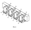
- FIG. 3 shows an embodiment in which a plurality of anvils 1 a to 1 d are arranged side by side on a plurality of parallel levers 2 a to 2 d.
- the individual anvils are stored here independently of each other, so that each anvil can be oriented individually by the parallel lever and the pivoting of the respective holder 3a to 3d.
- the holders 3 are then arranged on a common carrier 5 in order to obtain a compact design.
- each anvil is associated with a separate ultrasonic hammer.
- the bags or other article to be welded may be fed to the anvils in one direction along the row of anvils or side by side in a direction perpendicular thereto.
- a two-part welding lip 15 is provided. This leads to two adjacent welds with which a seal of z. B. foil bags is ensured in a particularly secure manner.
- By the storage of the anvil 1 on the parallel lever 2 can always be both sealing lips in contact with the anvil 16, regardless of the deflection of the anvil from its rest position. This is advantageous for the production of good sealing welds.
Abstract
Description
Die Erfindung betrifft einen Amboss und eine Vorrichtung zum Ultraschallschweißen. Ein solcher Amboss und eine solche Vorrichtung werden beispielsweise zum Verschließen von Folienbeuteln eingesetzt, bei denen nach dem Befüllen der Folienbeutel das obere Ende hiervon verschlossen werden muss. Zum Verschließen der Folienbeutel wird das obere Ende zwischen Ultraschallhammer- und Amboss eingeklemmt und dann durch Anlegen von Ultraschall, der von dem Ultraschallhammer ausgesandt wird, zugeschweißt.The invention relates to an anvil and a device for ultrasonic welding. Such an anvil and such an apparatus are used for example for closing foil bags, in which after filling the foil bag, the upper end thereof must be closed. To seal the foil bags, the upper end is clamped between the ultrasonic hammer and anvil and then sealed by applying ultrasound emitted from the ultrasonic hammer.
Für eine gute Schweißnaht ist es vorteilhaft, dass Amboss und Ultraschallhammer gut flächigen Kontakt haben, um so die Einkopplung der Ultraschallwellen in das Folienmaterial flächig zu gewährleisten.For a good weld, it is advantageous that anvil and ultrasonic hammer have good surface contact, so as to ensure the coupling of the ultrasonic waves in the sheet material area.
Um das zu verschweißende Material zwischen Ultraschallhammer und Amboss einklemmen zu können, müssen diese beiden Teile beweglich gegeneinander ausgebildet sein.In order to clamp the material to be welded between ultrasonic hammer and anvil, these two parts must be movable against each other.
Die
Die
Die
Die
Die
Aufgabe der vorliegenden Erfindung ist es, diese Beweglichkeit so zu erhalten, dass gut dichtende Schweißnähte erhalten werden und die Vorrichtung wenig Abnutzung zeigt.Object of the present invention is to obtain this mobility so that good sealing welds are obtained and the device shows little wear.
Diese Aufgabe wird gelöst durch einen Amboss nach Anspruch 1 und eine Vorrichtung nach Anspruch 7. Bevorzugte Ausführungsformen sind in den Unteransprüchen offenbart.This object is achieved by an anvil according to claim 1 and an apparatus according to
Erfindungsgemäß ist der Amboss an einem Parallelhebel gelagert. Durch diese Lagerung wird die Parallelität der Oberfläche des Ambosses und des Ultraschallhammers bei jeder Position gewährleistet. Dadurch wird ein Abrieb zwischen Amboss und Ultraschallhammer minimiert, da immer ein flächiger Kontakt bei den verschiedenen Positi- onen, die Amboss und Ultraschallhammer relativ zueinander einnehmen können, gegeben ist.According to the invention, the anvil is mounted on a parallel lever. By this storage, the parallelism of the surface of the anvil and the ultrasonic hammer is ensured at each position. As a result, abrasion between the anvil and the ultrasonic hammer is minimized, since there is always surface contact with the various positives. Ones that can take the anvil and ultrasonic hammer relative to each other, is given.
Bevorzugterweise ist der Amboss hängend an dem Parallelhebel gelagert, um so eine definierte Ruheposition vorzugeben.Preferably, the anvil is suspended from the parallel lever, so as to specify a defined rest position.
Der Parallelhebel ist vorzugsweise an einem Halter befestigt, wobei der Halter selbst um eine Achse schwenkbar ist. Falls diese Achse in etwa senkrecht zu den Achsen liegt, um die der Parallelhebel schwenkt, dann kann sich der Amboss in zwei Dimensionen der Lage und Orientierung des Ultraschallhammers anpassen, sodass ein gleichmäßiger Kontaktdruck zwischen Ultraschallhammer und Amboss entlang der Schweißstelle gewährleistet wird.The parallel lever is preferably attached to a holder, wherein the holder itself is pivotable about an axis. If this axis is approximately perpendicular to the axes about which the parallel lever pivots, then the anvil can adapt in two dimensions to the position and orientation of the ultrasonic hammer so that a uniform contact pressure between ultrasonic hammer and anvil along the weld is ensured.
Der Amboss ist weiterhin vorzugsweise mit Vorspannmitteln in Richtung zu einem Ultraschallhammer vorgespannt. Dadurch kann der Ultraschallhammer das zu schweißende Material (z. B. Folienbeutel) gegen den Amboss drücken und den Amboss leicht zurückdrücken, sodass ein vordefinierter Druck zwischen Amboss und Ultraschallhammer wirkt.The anvil is further preferably biased with biasing means towards an ultrasonic hammer. This allows the ultrasonic hammer to press the material to be welded (eg foil pouch) against the anvil and slightly push back the anvil so that a predefined pressure acts between the anvil and the ultrasonic hammer.
Weiterhin ist der Amboss vorzugsweise mit einem Dämpfungsmittel gekoppelt, das eine Bewegung des Ambosses dämpft. Dadurch wird erreicht, dass nach Zusammenführen von Ultraschallhammer und Amboss sich möglichst schnell der bleibende Kontakt zwischen Hammer und Amboss mit dem dazwischen eingeklemmten Schweißmaterial ergibt. Ein etwaiges Prellen kann so weitgehend unterdrückt werden.Furthermore, the anvil is preferably coupled to a damping means which dampens movement of the anvil. This ensures that after merging of ultrasonic hammer and anvil as quickly as possible, the permanent contact between the hammer and anvil results with the clamped in between welding material. Any bouncing can be suppressed as much as possible.
Vorteilhaft ist eine Ausführungsform, bei der mehrere Ambosse parallel nebeneinander angeordnet sind. Zum Schweißen von mehreren Schweißstellen, ist es möglich, mehrere Schweißstellen mit ein- und demselben Amboss zu schweißen. Weiterhin ist es möglich, mehrere unabhängige Ambosse nebeneinander vorzusehen. Letzteres hat den Vorteil, dass sich der Amboss individuell in seiner Position dem Ultraschallhammer bzw. dem dazwischen eingeklemmten Material anpassen kann, sodass über die Schweißstelle hinweg ein gleichmäßiger Druck gewährleistet wird. Je größer der Amboss, desto schwieriger ist es, über die gesamte Schweißstelle hinweg einen gleichbleibenden Druck zu erreichen. Hierzu ist auch vorzugsweise der Parallelhebel an einem eigenen schwenkbaren Halter angeordnet.An embodiment in which a plurality of anvils are arranged parallel to one another is advantageous. For welding several welds, it is possible to weld several welds with one and the same anvil. Furthermore, it is possible to provide several independent anvils side by side. The latter has the advantage that the anvil can adapt individually in its position to the ultrasonic hammer or the material clamped therebetween, so that uniform pressure is ensured across the weld. The larger the anvil, the harder it is to have a consistent one throughout the weld To reach pressure. For this purpose, the parallel lever is preferably arranged on a separate pivotable holder.
Zur Vereinfachung der Konstruktion sind mehrere schwenkbare Halter an einem gemeinsamen Träger gelagert.To simplify the construction, a plurality of pivotable holders are mounted on a common carrier.
Eine beispielhafte Ausführungsform der Erfindung ist in den Figuren gezeigt. Dabei zeigt:
- Figur 1
- eine dreidimensionale schematische Darstellung eines Ambosses und seiner Lagerung;
Figur 2- eine schematische Schnittzeichnung der Vorrichtung aus Figur 1;
Figur 3- eine dreidimensionale schematische Darstellung von mehreren Ambossen nebeneinander.
- FIG. 1
- a three-dimensional schematic representation of an anvil and its storage;
- FIG. 2
- a schematic sectional view of the device of Figure 1;
- FIG. 3
- a three-dimensional schematic representation of several anvils next to each other.
In Figur 1 und 2 ist ein Amboss 1 gezeigt, der an einem hängenden Parallelhebel 2 hängt. Der Parallelhebel 2 weist zwei Hebel 6, 7 auf, die um Achsen 8, 9 schwenkbar gelagert sind und parallel zueinander ausgerichtet sind. Am unteren Ende des Parallelhebels sind zwei Querstücke 13 vorgesehen, die die beiden unteren Enden der Parallelhebel 6, 7 miteinander verbinden. Hierbei sind zwei schwenkbare Achsen 11 und 12 vorgesehen. Der Amboss 1 ist an den unteren Querteilen 13 angeordnet. Die Achsen 8 und 9 sind in oberen Querteilen 10 gelagert, die ihrerseits an einem Halter 3 befestigt sind. Der Halter 3 erstreckt sich von dem Parallelhebel 2 im Wesentlichen in horizontaler Richtung weg. An seinem Ende ist der Halter 3 schwenkbar um eine Achse 4 gelagert. Der Halter 3 ist mit dieser Achse auf einem Träger 5 gelagert.In Figures 1 and 2, an anvil 1 is shown, which hangs on a hanging
Der Amboss 1 weist an seiner Vorderseite Schweißlippen 15 auf, wobei hier sowohl eine einzelne Schweißlippe als auch mehrere Lippen vorgesehen sein können, je nachdem, wie viele Schweißnähte ausgebildet werden sollen. Die Anordnung von zwei Schweißnähten dicht nebeneinander hat sich als sehr vorteilhaft erwiesen.The anvil 1 has at its
An der der Schweißlippe 15 abgewandten Seite greift ein Element 14 an. Statt direkt an den Amboss anzugreifen kann es auch an den Parallelhebel oder ein sonstiges bewegliches Teil angreifen. Dieses Element 14 kann eine federnde und/oder eine dämpfende Wirkung haben. Mit dem Element 14 oder einem anderen federnden Element wird der Amboss 1 in Richtung zu einem Ultraschallhammer hin vorgespannt. Das Element 14 oder das andere federnde Element kann einen Kolben aufweisen, der gegen den Amboss 1 drückt, sei es durch Druckluft, durch die Kraft einer Feder oder eines elastischen Elements oder durch eine sonstige Kraft.At the side facing away from the
Das Element 14 oder ein daneben angeordnetes Element, das mit dem Amboss 1 oder einem beweglichen Teil des Parallelhebels 2 zusammenwirkt, kann auch dämpfend auf die Bewegung des Ambosses 1 und des Parallelhebels 2 wirken, um so die Bewegung des Ambosses 1 zu dämpfen. Dies ist insbesondere bei einem Schweißen mit hohen Geschwindigkeiten von Vorteil, da nach Zusammenführen von Ultraschallhammer 16 und Amboss 1 möglichst schnell eine ruhige Lage des Ambosses 1 erreicht werden soll, um mit dem dann gleichmäßig vorliegenden Druck das Ultraschallschweißen vornehmen zu können.The
Vorzugsweise ist an jedem Ende des Ambosses 1 ein Element 14 vorgesehen, also vorzugsweise zwei Elemente 14 je Amboss.Preferably, an
Das federnde Element (z. B. Element 14), das den Amboss 1 in Richtung zu dem Ultraschallhammer 16 vorspannt, kann so ausgestaltet sein, dass es den Amboss nur bis in eine gewisse Maximalauslenkung in Richtung des Ultraschallhammers 16 vorspannt, den Amboss jedoch nicht weiter auszulenken vermag. In diesem Fall ist es sinnvoll, ein weiteres Element vorzusehen, das den Parallelhebel 2 oder den Amboss 1 gegen das federnde Element (z. B. Element 14) in diese Position leicht vorspannt, um dem Amboss 1 so eine definierte Position zu geben. Die Kraft, die den Amboss 1 in Richtung auf das federnde Element vorspannt, sollte dann kleiner sein, als die Kraft, die durch das federnde Element zur Verfügung gestellt wird.The resilient element (eg, element 14) that biases the anvil 1 toward the
Der Ultraschallhammer 16 in Figur 2 kann von dem Amboss 1 wegbewegt werden, um das obere Ende des Schweißmaterials 17 (eines Folienbeutels) zwischen Amboss 1 und Ultraschallhammer 16 einzuklemmen. Dazu wird der Ultraschallhammer 16 dann auf den Amboss 1 draufgeschoben, wobei das Material 17 eingeklemmt wird. Der Amboss 1 wird sich dabei in Figur 2 leicht nach rechts verlagern, entgegen der Vorspannkraft durch das federnde Element 14.The
In dieser Position mit dem kontrollierten Druck zwischen Ultraschallhammer 16 und Amboss 1 kann das Schweißen des Materials 17 gut durchgeführt werden.In this position with the controlled pressure between
Es kann jedoch auch der Träger 5 beweglich ausgestaltet sein, um den Amboss daran von dem Ultraschallhammer wegzubewegen. Dadurch wird der Platz geschaffen, um die Folienbeutel zwischen Ultraschallhammer und Amboss einzuführen. Durch eine Bewegung des Trägers 5 in Richtung zu dem Ultraschallhammer wird das zu schweißende Material 17 dann eingeklemmt.However, the
In Figur 3 ist eine Ausführungsform gezeigt, bei der mehrere Ambosse 1 a bis 1 d an mehreren Parallelhebeln 2 a bis 2 d nebeneinander angeordnet sind. Mit einer solchen Vorrichtung ist es möglich, mehrere Schweißvorgänge von mehreren Materialien nebeneinander durchzuführen. Beispielsweise ist es hiermit möglich, mehrere Folienbeutel nebeneinander zu verschweißen. Hiermit können Durchsatzraten signifikant erhöht werden. Die einzelnen Ambosse sind hier unabhängig voneinander gelagert, sodass sich jeder Amboss individuell durch den Parallelhebel und die Schwenkbarkeit des jeweiligen Halters 3a bis 3d orientieren kann. Die Halter 3 sind dann jedoch an einem gemeinsamen Träger 5 angeordnet, um eine kompakte Bauweise zu erhalten.FIG. 3 shows an embodiment in which a plurality of
Vorzugsweise ist jedem Amboss ein separater Ultraschallhammer zugeordnet. Es ist jedoch auch möglich mehreren Ambossen oder allen Ambossen genau einen Ultraschallhammer zuzuordnen.Preferably, each anvil is associated with a separate ultrasonic hammer. However, it is also possible to assign exactly one anvil to several anvils or all anvils.
Die Beutel oder andere zu schweißende Artikel können den Ambossen in einer Richtung entlang der Reihe der Ambosse zugeführt werden oder auch nebeneinander in einer Richtung senkrecht dazu.The bags or other article to be welded may be fed to the anvils in one direction along the row of anvils or side by side in a direction perpendicular thereto.
Wie in den Figuren 1 bis 3 zu erkennen, ist eine zweiteilige Schweißlippe 15 vorgesehen. Dies führt zu zwei nebeneinanderliegenden Schweißnähten mit denen eine Abdichtung von z. B. Folienbeuteln in besonders sicherer Weise gewährleistet wird. Durch die Lagerung des Ambosses 1 an dem Parallelhebel 2 können immer beide Dichtlippen mit dem Amboss 16 in Kontakt sein, unabhängig von der Auslenkung des Ambosses aus seiner Ruhelage heraus. Dies ist für die Anfertigung von gut dichtenden Schweißnähten vorteilhaft.As can be seen in FIGS. 1 to 3, a two-
Dadurch, dass der Druck auf die beiden Schweißlippen immer in etwa gleich groß ist, verschleißt auch keine von diesen beiden Schweißlippen durch die Reibung bei der Bewegung zwischen Amboss 1 und Ultraschallhammer 16 stärker als die andere, sodass die Standzeiten hier sehr gut sind.Due to the fact that the pressure on the two welding lips is always approximately the same, neither of these two welding lips wears out more than the other due to the friction between the anvil 1 and the
Claims (12)
gekennzeichnet durch
eine Lagerung des Ambosses (1) an einem Parallelhebel (2).Anvil (1) for ultrasonic welding
marked by
a storage of the anvil (1) on a parallel lever (2).
Priority Applications (22)
| Application Number | Priority Date | Filing Date | Title |
|---|---|---|---|
| RS20120576A RS52603B (en) | 2006-05-11 | 2006-05-11 | Device for ultrasonic welding |
| EP06009789A EP1854618B1 (en) | 2006-05-11 | 2006-05-11 | Device for ultrasonic welding |
| PT60097896T PT1854618E (en) | 2006-05-11 | 2006-05-11 | Device for ultrasonic welding |
| ES06009789T ES2401081T3 (en) | 2006-05-11 | 2006-05-11 | Ultrasonic welding device |
| DK06009789.6T DK1854618T3 (en) | 2006-05-11 | 2006-05-11 | Device for ultrasonic welding |
| SI200631532T SI1854618T1 (en) | 2006-05-11 | 2006-05-11 | Device for ultrasonic welding |
| PL06009789T PL1854618T3 (en) | 2006-05-11 | 2006-05-11 | Device for ultrasonic welding |
| TW096108825A TWI359768B (en) | 2006-05-11 | 2007-03-14 | Anvil for ultrasonic welding and device for ultras |
| CA2582014A CA2582014C (en) | 2006-05-11 | 2007-03-16 | Anvil for ultrasonic welding and device for ultrasonic welding |
| RU2007111481/11A RU2359828C2 (en) | 2006-05-11 | 2007-03-28 | Support and device for ultrasonic welding |
| SA7280190A SA07280190B1 (en) | 2006-05-11 | 2007-04-18 | Anvil for Ultrasonic Welding and Device for Ultrasonic Welding |
| JP2007110809A JP4703598B2 (en) | 2006-05-11 | 2007-04-19 | Ultrasonic welding anvil and ultrasonic welding equipment |
| CN2007101044420A CN101069989B (en) | 2006-05-11 | 2007-04-20 | Anvil for ultrasonic welding as well as device for ultrasonic welding |
| ZA200703334A ZA200703334B (en) | 2006-05-11 | 2007-04-24 | Anvil for ultrasonic welding and device for ultrasonic welding |
| BRPI0701895-9A BRPI0701895A (en) | 2006-05-11 | 2007-04-25 | ultrasonic welding stop and ultrasonic welding device |
| UAA200705095A UA89647C2 (en) | 2006-05-11 | 2007-05-08 | device for ultrasonic welding |
| KR1020070045704A KR100906211B1 (en) | 2006-05-11 | 2007-05-10 | Anvil for ultrasonic welding and device for ultrasonic welding |
| MX2007005717A MX2007005717A (en) | 2006-05-11 | 2007-05-11 | Anvil for ultrasonic welding and device for ultrasonic welding . |
| ARP070102039A AR060888A1 (en) | 2006-05-11 | 2007-05-11 | YUNQUE FOR ULTRASONIC WELDING AND DEVICE FOR ULTRASONIC WELDING |
| US11/747,611 US7810541B2 (en) | 2006-05-11 | 2007-05-11 | Anvil for ultrasonic welding and device for ultrasonic welding |
| HK08102405.7A HK1113110A1 (en) | 2006-05-11 | 2008-03-04 | Device for ultrasonic welding |
| HRP20130005TT HRP20130005T1 (en) | 2006-05-11 | 2013-01-03 | Device for ultrasonic welding |
Applications Claiming Priority (1)
| Application Number | Priority Date | Filing Date | Title |
|---|---|---|---|
| EP06009789A EP1854618B1 (en) | 2006-05-11 | 2006-05-11 | Device for ultrasonic welding |
Publications (2)
| Publication Number | Publication Date |
|---|---|
| EP1854618A1 true EP1854618A1 (en) | 2007-11-14 |
| EP1854618B1 EP1854618B1 (en) | 2012-12-12 |
Family
ID=36968864
Family Applications (1)
| Application Number | Title | Priority Date | Filing Date |
|---|---|---|---|
| EP06009789A Active EP1854618B1 (en) | 2006-05-11 | 2006-05-11 | Device for ultrasonic welding |
Country Status (22)
| Country | Link |
|---|---|
| US (1) | US7810541B2 (en) |
| EP (1) | EP1854618B1 (en) |
| JP (1) | JP4703598B2 (en) |
| KR (1) | KR100906211B1 (en) |
| CN (1) | CN101069989B (en) |
| AR (1) | AR060888A1 (en) |
| BR (1) | BRPI0701895A (en) |
| CA (1) | CA2582014C (en) |
| DK (1) | DK1854618T3 (en) |
| ES (1) | ES2401081T3 (en) |
| HK (1) | HK1113110A1 (en) |
| HR (1) | HRP20130005T1 (en) |
| MX (1) | MX2007005717A (en) |
| PL (1) | PL1854618T3 (en) |
| PT (1) | PT1854618E (en) |
| RS (1) | RS52603B (en) |
| RU (1) | RU2359828C2 (en) |
| SA (1) | SA07280190B1 (en) |
| SI (1) | SI1854618T1 (en) |
| TW (1) | TWI359768B (en) |
| UA (1) | UA89647C2 (en) |
| ZA (1) | ZA200703334B (en) |
Cited By (5)
| Publication number | Priority date | Publication date | Assignee | Title |
|---|---|---|---|---|
| EP2113370A1 (en) | 2008-04-29 | 2009-11-04 | Tetra Laval Holdings & Finance SA | Sealing jaw for producing sealed packages of a food product |
| DE102009002675A1 (en) * | 2009-04-27 | 2010-10-28 | Herrmann Ultraschalltechnik Gmbh & Co. Kg | Ultrasonic sealing device and method for sealing webs of material |
| DE102016112757A1 (en) * | 2016-07-12 | 2018-01-18 | Herrmann Ultraschalltechnik Gmbh & Co. Kg | Ultrasonic machining device |
| DE102020117463A1 (en) | 2020-07-02 | 2022-01-05 | Herrmann Ultraschalltechnik Gmbh & Co. Kg | Counter tool, ultrasonic welding machine as well as methods for creating a sealing and cosmetic seam |
| US11660688B2 (en) | 2019-09-05 | 2023-05-30 | Ms Ultraschall Technologie Gmbh | Ultrasonic machining apparatus |
Families Citing this family (13)
| Publication number | Priority date | Publication date | Assignee | Title |
|---|---|---|---|---|
| US9038688B2 (en) | 2009-04-29 | 2015-05-26 | Covidien Lp | System and method for making tapered looped suture |
| US8403019B2 (en) * | 2010-05-24 | 2013-03-26 | Lg Chem, Ltd. | Ultrasonic welding assembly and method of attaching an anvil to a bracket of the assembly |
| US9005799B2 (en) | 2010-08-25 | 2015-04-14 | Lg Chem, Ltd. | Battery module and methods for bonding cell terminals of battery cells together |
| GB2484267A (en) * | 2010-10-01 | 2012-04-11 | Concepts For Success | Ultrasonic welding using helical anvil |
| US9034129B2 (en) | 2011-01-13 | 2015-05-19 | Lg Chem, Ltd. | Ultrasonic welding system and method for forming a weld joint utilizing the ultrasonic welding system |
| US8640760B2 (en) * | 2011-08-19 | 2014-02-04 | Lg Chem, Ltd. | Ultrasonic welding machine and method of aligning an ultrasonic welding horn relative to an anvil |
| US8695867B2 (en) | 2011-08-31 | 2014-04-15 | Lg Chem, Ltd. | Ultrasonic welding machine and method of assembling the ultrasonic welding machine |
| JP6258648B2 (en) * | 2013-09-20 | 2018-01-10 | 株式会社イシダ | Packaging machine |
| FR3019083B1 (en) | 2014-04-01 | 2016-12-30 | Sonimat | ULTRASONIC SOLDERING DEVICE |
| DE102016004180A1 (en) | 2016-04-11 | 2017-10-12 | Focke & Co. (Gmbh & Co. Kg) | Apparatus for ultrasonic welding |
| CN107262907A (en) * | 2017-07-19 | 2017-10-20 | 上海峥集机械设备有限公司 | A kind of full servo supersonic welder |
| WO2019238497A1 (en) * | 2018-06-12 | 2019-12-19 | Tetra Laval Holdings & Finance S.A. | A method for sealing together a first section and a second section of a piece of packaging material, an anvil assembly and a system comprising such assembly |
| DE102021124530A1 (en) | 2021-09-22 | 2023-03-23 | Sig Technology Ag | Device for ultrasonic welding of composite material |
Citations (6)
| Publication number | Priority date | Publication date | Assignee | Title |
|---|---|---|---|---|
| US2834395A (en) * | 1954-12-10 | 1958-05-13 | American Viscose Corp | Apparatus for joining thermoplastic sheets |
| JPS52125540A (en) * | 1976-04-15 | 1977-10-21 | Seidensha Electronics | Ultrasonic continuous solvent welding method of plastic film and cloth etc |
| JPS5658822A (en) * | 1979-10-17 | 1981-05-22 | Yuasa Battery Co Ltd | Ultrasonic fusing mechanism |
| US6313440B1 (en) * | 1998-03-27 | 2001-11-06 | Kvt Technologies Inc. | Hot plate welding system |
| FR2829962A1 (en) * | 2001-09-26 | 2003-03-28 | Varta Microbattery Gmbh | Voltaic cell container sealing apparatus has anvil plate with guides and springs for sonotrode |
| WO2006041380A1 (en) * | 2004-10-15 | 2006-04-20 | Tetra Laval Holdings & Finance S.A. | A counter jaw arrangement |
Family Cites Families (14)
| Publication number | Priority date | Publication date | Assignee | Title |
|---|---|---|---|---|
| JPS5948815U (en) * | 1982-09-22 | 1984-03-31 | 東郷樹脂株式会社 | Ultrasonic welding equipment |
| JPS6167584A (en) * | 1984-09-10 | 1986-04-07 | Konishiroku Photo Ind Co Ltd | Ultrasonic welding method and its equipment |
| JPH04371397A (en) * | 1991-06-19 | 1992-12-24 | Amada Co Ltd | Work clamp device in welding machine |
| JPH0721335U (en) * | 1993-09-27 | 1995-04-18 | 米雄 津田 | Ultrasonic welding machine |
| US5601669A (en) * | 1994-10-04 | 1997-02-11 | Portola Packaging, Inc. | Apparatus and method for attaching fitments to cartons |
| CN1061292C (en) * | 1995-01-27 | 2001-01-31 | 铃木三次 | Apparatus for adhering and cutting synthetic resin packaging material |
| FR2784051B1 (en) * | 1998-10-06 | 2000-12-22 | Unisabi Sa | ULTRASONIC WELDING DEVICE |
| CN2352328Y (en) * | 1998-11-17 | 1999-12-08 | 欣瑞机械股份有限公司 | Machine for quick melt joining of file bag |
| JP2000202912A (en) * | 1999-01-18 | 2000-07-25 | Kyoshin Sekkei:Kk | Ultrasonic fusion-bonding device |
| JP2003007154A (en) | 2001-06-21 | 2003-01-10 | Sumitomo Wiring Syst Ltd | Flat cable manufacturing device |
| JP2004331109A (en) * | 2003-05-01 | 2004-11-25 | Toyo Jidoki Co Ltd | Ultrasonic sealing device |
| JP4293003B2 (en) * | 2004-02-03 | 2009-07-08 | 株式会社デンソー | Ultrasonic welding equipment |
| BRPI0518538B1 (en) | 2005-01-03 | 2016-12-20 | 3M Innovative Properties Co | apparatus for contacting a continuous sheet of indefinite length |
| ES2369607T3 (en) * | 2005-07-20 | 2011-12-02 | Indag Gesellschaft für Industriebedarf mbH & Co. Betriebs KG | DEVICE AND PROCEDURE FOR APPLYING A WELDING SEWING, AS WELL AS SHEET BAG. |
-
2006
- 2006-05-11 SI SI200631532T patent/SI1854618T1/en unknown
- 2006-05-11 EP EP06009789A patent/EP1854618B1/en active Active
- 2006-05-11 PT PT60097896T patent/PT1854618E/en unknown
- 2006-05-11 DK DK06009789.6T patent/DK1854618T3/en active
- 2006-05-11 PL PL06009789T patent/PL1854618T3/en unknown
- 2006-05-11 RS RS20120576A patent/RS52603B/en unknown
- 2006-05-11 ES ES06009789T patent/ES2401081T3/en active Active
-
2007
- 2007-03-14 TW TW096108825A patent/TWI359768B/en not_active IP Right Cessation
- 2007-03-16 CA CA2582014A patent/CA2582014C/en not_active Expired - Fee Related
- 2007-03-28 RU RU2007111481/11A patent/RU2359828C2/en not_active IP Right Cessation
- 2007-04-18 SA SA7280190A patent/SA07280190B1/en unknown
- 2007-04-19 JP JP2007110809A patent/JP4703598B2/en active Active
- 2007-04-20 CN CN2007101044420A patent/CN101069989B/en active Active
- 2007-04-24 ZA ZA200703334A patent/ZA200703334B/en unknown
- 2007-04-25 BR BRPI0701895-9A patent/BRPI0701895A/en not_active Application Discontinuation
- 2007-05-08 UA UAA200705095A patent/UA89647C2/en unknown
- 2007-05-10 KR KR1020070045704A patent/KR100906211B1/en not_active IP Right Cessation
- 2007-05-11 US US11/747,611 patent/US7810541B2/en active Active
- 2007-05-11 AR ARP070102039A patent/AR060888A1/en not_active Application Discontinuation
- 2007-05-11 MX MX2007005717A patent/MX2007005717A/en active IP Right Grant
-
2008
- 2008-03-04 HK HK08102405.7A patent/HK1113110A1/en not_active IP Right Cessation
-
2013
- 2013-01-03 HR HRP20130005TT patent/HRP20130005T1/en unknown
Patent Citations (6)
| Publication number | Priority date | Publication date | Assignee | Title |
|---|---|---|---|---|
| US2834395A (en) * | 1954-12-10 | 1958-05-13 | American Viscose Corp | Apparatus for joining thermoplastic sheets |
| JPS52125540A (en) * | 1976-04-15 | 1977-10-21 | Seidensha Electronics | Ultrasonic continuous solvent welding method of plastic film and cloth etc |
| JPS5658822A (en) * | 1979-10-17 | 1981-05-22 | Yuasa Battery Co Ltd | Ultrasonic fusing mechanism |
| US6313440B1 (en) * | 1998-03-27 | 2001-11-06 | Kvt Technologies Inc. | Hot plate welding system |
| FR2829962A1 (en) * | 2001-09-26 | 2003-03-28 | Varta Microbattery Gmbh | Voltaic cell container sealing apparatus has anvil plate with guides and springs for sonotrode |
| WO2006041380A1 (en) * | 2004-10-15 | 2006-04-20 | Tetra Laval Holdings & Finance S.A. | A counter jaw arrangement |
Non-Patent Citations (1)
| Title |
|---|
| PATENT ABSTRACTS OF JAPAN vol. 005, no. 119 (M - 081) 31 July 1981 (1981-07-31) * |
Cited By (9)
| Publication number | Priority date | Publication date | Assignee | Title |
|---|---|---|---|---|
| EP2113370A1 (en) | 2008-04-29 | 2009-11-04 | Tetra Laval Holdings & Finance SA | Sealing jaw for producing sealed packages of a food product |
| WO2009133077A1 (en) * | 2008-04-29 | 2009-11-05 | Tetra Laval Holdings & Finance S.A. | Sealing jaw for producing sealed packages of a food product |
| CN102015255A (en) * | 2008-04-29 | 2011-04-13 | 利乐拉瓦尔集团及财务有限公司 | Sealing jaw for producing sealed packages of a food product |
| US7950208B2 (en) | 2008-04-29 | 2011-05-31 | Tetra Laval Holdings & Finance S.A. | Sealing jaw for producing sealed packages of a food product |
| DE102009002675A1 (en) * | 2009-04-27 | 2010-10-28 | Herrmann Ultraschalltechnik Gmbh & Co. Kg | Ultrasonic sealing device and method for sealing webs of material |
| US8557071B2 (en) | 2009-04-27 | 2013-10-15 | Herrmann Ultraschalltechnik Gmbh & Co. Kg | Ultrasound welding device and method for welding material webs |
| DE102016112757A1 (en) * | 2016-07-12 | 2018-01-18 | Herrmann Ultraschalltechnik Gmbh & Co. Kg | Ultrasonic machining device |
| US11660688B2 (en) | 2019-09-05 | 2023-05-30 | Ms Ultraschall Technologie Gmbh | Ultrasonic machining apparatus |
| DE102020117463A1 (en) | 2020-07-02 | 2022-01-05 | Herrmann Ultraschalltechnik Gmbh & Co. Kg | Counter tool, ultrasonic welding machine as well as methods for creating a sealing and cosmetic seam |
Also Published As
| Publication number | Publication date |
|---|---|
| ES2401081T3 (en) | 2013-04-16 |
| HRP20130005T1 (en) | 2013-01-31 |
| US20080105385A1 (en) | 2008-05-08 |
| SI1854618T1 (en) | 2013-03-29 |
| KR20070109929A (en) | 2007-11-15 |
| CN101069989A (en) | 2007-11-14 |
| DK1854618T3 (en) | 2013-03-18 |
| ZA200703334B (en) | 2008-06-25 |
| RU2359828C2 (en) | 2009-06-27 |
| TWI359768B (en) | 2012-03-11 |
| US7810541B2 (en) | 2010-10-12 |
| BRPI0701895A (en) | 2008-01-02 |
| JP2007307617A (en) | 2007-11-29 |
| CA2582014C (en) | 2010-05-18 |
| RS52603B (en) | 2013-04-30 |
| CA2582014A1 (en) | 2007-11-11 |
| HK1113110A1 (en) | 2008-09-26 |
| TW200742708A (en) | 2007-11-16 |
| AR060888A1 (en) | 2008-07-23 |
| EP1854618B1 (en) | 2012-12-12 |
| PL1854618T3 (en) | 2013-05-31 |
| KR100906211B1 (en) | 2009-07-07 |
| PT1854618E (en) | 2013-01-23 |
| UA89647C2 (en) | 2010-02-25 |
| JP4703598B2 (en) | 2011-06-15 |
| CN101069989B (en) | 2010-09-15 |
| MX2007005717A (en) | 2008-11-26 |
| RU2007111481A (en) | 2008-10-27 |
| SA07280190B1 (en) | 2011-05-04 |
Similar Documents
| Publication | Publication Date | Title |
|---|---|---|
| EP1854618A1 (en) | Anvil for ultrasonic welding as well as device for ultrasonic welding | |
| EP1745916B1 (en) | Device and process for applying a weld seam as well as film bag | |
| CH668235A5 (en) | CROSS-LOCKING DEVICE FOR PRODUCTS-FILLED BAGS FROM A TUBULAR FILM. | |
| DE112011102493B4 (en) | Device for vibro spot welding | |
| DE10301347A1 (en) | Packaging tax band application machine has a film changeover unit with a film sealing unit to produce a welded and cut transverse seam between old and new film strips and old strip and new strip leader | |
| EP1932651B1 (en) | Ultrasonic welding apparatus and device for handling film bags | |
| DE2933302B1 (en) | Device for welding tapes lying on top of one another made of thermoplastic material | |
| DE2405943C3 (en) | Heat sealing device for joining two webs of packaging material | |
| DE2200208A1 (en) | Device for tying objects | |
| WO2017001153A1 (en) | Device for the processing, in particular for the ultrasonic welding, of packaging casings and use of the device | |
| DE102004049375A1 (en) | Method and device for positioning a welding jaw | |
| DE1479770A1 (en) | Device for welding together webs, sheets or sheets made of thermoplastic material | |
| EP3419810B1 (en) | Strapping device with an ultrasonic welding device | |
| DE102013217647A1 (en) | Beam-supported joining machine, in particular laser penetrating welding device | |
| WO2007131573A2 (en) | Device for welding a film web | |
| DE2928847C2 (en) | Device for processing a tube made of packaging material | |
| DE3420267A1 (en) | FLUID ACTUATING ORGAN | |
| DE102021125155A1 (en) | Sealing device and longitudinal sealing device with such a sealing device | |
| DE102019128328B3 (en) | Method for joining tape ends | |
| DE1604613C3 (en) | Device for cutting and welding thermoplastic tubing or folded foils | |
| WO2023135280A1 (en) | Weld seam, method and device for connecting plastics films by thermal joining, and use of a blow-forging press | |
| DE1511754A1 (en) | Bracket fastening device | |
| DE102006025849A1 (en) | Welding device for foil path formed at tubular foil tube, has coupling unit moving transverse to moving direction of movable parts to lift, lower, open and close sealing jaws by relative movement of movable part and fixed part | |
| DE202013100866U1 (en) | Ultrasonic welding device with sonotrode | |
| DE1511802C (en) | Device for unfolding and fastening the folding tabs of rectangular packs to their end walls |
Legal Events
| Date | Code | Title | Description |
|---|---|---|---|
| PUAI | Public reference made under article 153(3) epc to a published international application that has entered the european phase |
Free format text: ORIGINAL CODE: 0009012 |
|
| 17P | Request for examination filed |
Effective date: 20061219 |
|
| AK | Designated contracting states |
Kind code of ref document: A1 Designated state(s): AT BE BG CH CY CZ DE DK EE ES FI FR GB GR HU IE IS IT LI LT LU LV MC NL PL PT RO SE SI SK TR |
|
| AX | Request for extension of the european patent |
Extension state: AL BA HR MK YU |
|
| AKX | Designation fees paid |
Designated state(s): AT BE BG CH CY CZ DE DK EE ES FI FR GB GR HU IE IS IT LI LT LU LV MC NL PL PT RO SE SI SK TR |
|
| AXX | Extension fees paid |
Extension state: AL Payment date: 20061219 Extension state: YU Payment date: 20061219 Extension state: HR Payment date: 20061219 Extension state: BA Payment date: 20061219 Extension state: MK Payment date: 20061219 |
|
| REG | Reference to a national code |
Ref country code: HK Ref legal event code: DE Ref document number: 1113110 Country of ref document: HK |
|
| GRAP | Despatch of communication of intention to grant a patent |
Free format text: ORIGINAL CODE: EPIDOSNIGR1 |
|
| GRAS | Grant fee paid |
Free format text: ORIGINAL CODE: EPIDOSNIGR3 |
|
| GRAA | (expected) grant |
Free format text: ORIGINAL CODE: 0009210 |
|
| AK | Designated contracting states |
Kind code of ref document: B1 Designated state(s): AT BE BG CH CY CZ DE DK EE ES FI FR GB GR HU IE IS IT LI LT LU LV MC NL PL PT RO SE SI SK TR |
|
| AX | Request for extension of the european patent |
Extension state: AL BA HR MK YU |
|
| REG | Reference to a national code |
Ref country code: GB Ref legal event code: FG4D Free format text: NOT ENGLISH |
|
| REG | Reference to a national code |
Ref country code: CH Ref legal event code: EP |
|
| REG | Reference to a national code |
Ref country code: AT Ref legal event code: REF Ref document number: 588118 Country of ref document: AT Kind code of ref document: T Effective date: 20121215 |
|
| REG | Reference to a national code |
Ref country code: HR Ref legal event code: TUEP Ref document number: P20130005 Country of ref document: HR |
|
| REG | Reference to a national code |
Ref country code: IE Ref legal event code: FG4D Free format text: LANGUAGE OF EP DOCUMENT: GERMAN |
|
| REG | Reference to a national code |
Ref country code: PT Ref legal event code: SC4A Free format text: AVAILABILITY OF NATIONAL TRANSLATION Effective date: 20130103 |
|
| REG | Reference to a national code |
Ref country code: HR Ref legal event code: T1PR Ref document number: P20130005 Country of ref document: HR |
|
| REG | Reference to a national code |
Ref country code: DE Ref legal event code: R096 Ref document number: 502006012296 Country of ref document: DE Effective date: 20130207 |
|
| REG | Reference to a national code |
Ref country code: NL Ref legal event code: T3 |
|
| REG | Reference to a national code |
Ref country code: DK Ref legal event code: T3 |
|
| REG | Reference to a national code |
Ref country code: SE Ref legal event code: TRGR |
|
| REG | Reference to a national code |
Ref country code: ES Ref legal event code: FG2A Ref document number: 2401081 Country of ref document: ES Kind code of ref document: T3 Effective date: 20130416 |
|
| PG25 | Lapsed in a contracting state [announced via postgrant information from national office to epo] |
Ref country code: LT Free format text: LAPSE BECAUSE OF FAILURE TO SUBMIT A TRANSLATION OF THE DESCRIPTION OR TO PAY THE FEE WITHIN THE PRESCRIBED TIME-LIMIT Effective date: 20121212 |
|
| REG | Reference to a national code |
Ref country code: GR Ref legal event code: EP Ref document number: 20130400512 Country of ref document: GR Effective date: 20130418 |
|
| REG | Reference to a national code |
Ref country code: LT Ref legal event code: MG4D |
|
| PG25 | Lapsed in a contracting state [announced via postgrant information from national office to epo] |
Ref country code: LV Free format text: LAPSE BECAUSE OF FAILURE TO SUBMIT A TRANSLATION OF THE DESCRIPTION OR TO PAY THE FEE WITHIN THE PRESCRIBED TIME-LIMIT Effective date: 20121212 |
|
| REG | Reference to a national code |
Ref country code: PL Ref legal event code: T3 |
|
| REG | Reference to a national code |
Ref country code: SK Ref legal event code: T3 Ref document number: E 13658 Country of ref document: SK |
|
| REG | Reference to a national code |
Ref country code: HK Ref legal event code: GR Ref document number: 1113110 Country of ref document: HK |
|
| PG25 | Lapsed in a contracting state [announced via postgrant information from national office to epo] |
Ref country code: EE Free format text: LAPSE BECAUSE OF FAILURE TO SUBMIT A TRANSLATION OF THE DESCRIPTION OR TO PAY THE FEE WITHIN THE PRESCRIBED TIME-LIMIT Effective date: 20121212 Ref country code: IS Free format text: LAPSE BECAUSE OF FAILURE TO SUBMIT A TRANSLATION OF THE DESCRIPTION OR TO PAY THE FEE WITHIN THE PRESCRIBED TIME-LIMIT Effective date: 20130412 |
|
| PG25 | Lapsed in a contracting state [announced via postgrant information from national office to epo] |
Ref country code: RO Free format text: LAPSE BECAUSE OF FAILURE TO SUBMIT A TRANSLATION OF THE DESCRIPTION OR TO PAY THE FEE WITHIN THE PRESCRIBED TIME-LIMIT Effective date: 20121212 |
|
| PLBE | No opposition filed within time limit |
Free format text: ORIGINAL CODE: 0009261 |
|
| STAA | Information on the status of an ep patent application or granted ep patent |
Free format text: STATUS: NO OPPOSITION FILED WITHIN TIME LIMIT |
|
| 26N | No opposition filed |
Effective date: 20130913 |
|
| REG | Reference to a national code |
Ref country code: HU Ref legal event code: AG4A Ref document number: E017349 Country of ref document: HU |
|
| PG25 | Lapsed in a contracting state [announced via postgrant information from national office to epo] |
Ref country code: CY Free format text: LAPSE BECAUSE OF FAILURE TO SUBMIT A TRANSLATION OF THE DESCRIPTION OR TO PAY THE FEE WITHIN THE PRESCRIBED TIME-LIMIT Effective date: 20121212 |
|
| PG25 | Lapsed in a contracting state [announced via postgrant information from national office to epo] |
Ref country code: MC Free format text: LAPSE BECAUSE OF FAILURE TO SUBMIT A TRANSLATION OF THE DESCRIPTION OR TO PAY THE FEE WITHIN THE PRESCRIBED TIME-LIMIT Effective date: 20121212 |
|
| REG | Reference to a national code |
Ref country code: DE Ref legal event code: R097 Ref document number: 502006012296 Country of ref document: DE Effective date: 20130913 |
|
| PG25 | Lapsed in a contracting state [announced via postgrant information from national office to epo] |
Ref country code: LU Free format text: LAPSE BECAUSE OF NON-PAYMENT OF DUE FEES Effective date: 20130511 |
|
| REG | Reference to a national code |
Ref country code: HR Ref legal event code: ODRP Ref document number: P20130005 Country of ref document: HR Payment date: 20160421 Year of fee payment: 11 |
|
| REG | Reference to a national code |
Ref country code: FR Ref legal event code: PLFP Year of fee payment: 11 |
|
| PGFP | Annual fee paid to national office [announced via postgrant information from national office to epo] |
Ref country code: BG Payment date: 20160516 Year of fee payment: 11 Ref country code: FI Payment date: 20160511 Year of fee payment: 11 Ref country code: GR Payment date: 20160526 Year of fee payment: 11 |
|
| PGFP | Annual fee paid to national office [announced via postgrant information from national office to epo] |
Ref country code: PL Payment date: 20160425 Year of fee payment: 11 Ref country code: HU Payment date: 20160504 Year of fee payment: 11 Ref country code: TR Payment date: 20160502 Year of fee payment: 11 Ref country code: SK Payment date: 20160422 Year of fee payment: 11 Ref country code: SI Payment date: 20160421 Year of fee payment: 11 Ref country code: DK Payment date: 20160512 Year of fee payment: 11 |
|
| REG | Reference to a national code |
Ref country code: FR Ref legal event code: PLFP Year of fee payment: 12 |
|
| PGFP | Annual fee paid to national office [announced via postgrant information from national office to epo] |
Ref country code: NL Payment date: 20170525 Year of fee payment: 12 |
|
| PGFP | Annual fee paid to national office [announced via postgrant information from national office to epo] |
Ref country code: CZ Payment date: 20170502 Year of fee payment: 12 Ref country code: CH Payment date: 20170518 Year of fee payment: 12 Ref country code: IE Payment date: 20170518 Year of fee payment: 12 Ref country code: GB Payment date: 20170525 Year of fee payment: 12 |
|
| PGFP | Annual fee paid to national office [announced via postgrant information from national office to epo] |
Ref country code: SE Payment date: 20170525 Year of fee payment: 12 Ref country code: PT Payment date: 20170502 Year of fee payment: 12 Ref country code: BE Payment date: 20170518 Year of fee payment: 12 Ref country code: AT Payment date: 20170524 Year of fee payment: 12 |
|
| REG | Reference to a national code |
Ref country code: HR Ref legal event code: PBON Ref document number: P20130005 Country of ref document: HR Effective date: 20170511 |
|
| REG | Reference to a national code |
Ref country code: DK Ref legal event code: EBP Effective date: 20170531 |
|
| PG25 | Lapsed in a contracting state [announced via postgrant information from national office to epo] |
Ref country code: FI Free format text: LAPSE BECAUSE OF NON-PAYMENT OF DUE FEES Effective date: 20170511 Ref country code: SK Free format text: LAPSE BECAUSE OF NON-PAYMENT OF DUE FEES Effective date: 20170511 Ref country code: HU Free format text: LAPSE BECAUSE OF NON-PAYMENT OF DUE FEES Effective date: 20170512 |
|
| REG | Reference to a national code |
Ref country code: SK Ref legal event code: MM4A Ref document number: E 13658 Country of ref document: SK Effective date: 20170511 |
|
| PG25 | Lapsed in a contracting state [announced via postgrant information from national office to epo] |
Ref country code: SI Free format text: LAPSE BECAUSE OF NON-PAYMENT OF DUE FEES Effective date: 20170512 Ref country code: GR Free format text: LAPSE BECAUSE OF NON-PAYMENT OF DUE FEES Effective date: 20171206 |
|
| REG | Reference to a national code |
Ref country code: SI Ref legal event code: KO00 Effective date: 20180111 |
|
| PG25 | Lapsed in a contracting state [announced via postgrant information from national office to epo] |
Ref country code: DK Free format text: LAPSE BECAUSE OF NON-PAYMENT OF DUE FEES Effective date: 20170531 |
|
| REG | Reference to a national code |
Ref country code: FR Ref legal event code: PLFP Year of fee payment: 13 |
|
| PG25 | Lapsed in a contracting state [announced via postgrant information from national office to epo] |
Ref country code: PL Free format text: LAPSE BECAUSE OF NON-PAYMENT OF DUE FEES Effective date: 20170511 |
|
| REG | Reference to a national code |
Ref country code: CH Ref legal event code: PL |
|
| REG | Reference to a national code |
Ref country code: SE Ref legal event code: EUG Ref country code: NL Ref legal event code: MM Effective date: 20180601 |
|
| REG | Reference to a national code |
Ref country code: AT Ref legal event code: MM01 Ref document number: 588118 Country of ref document: AT Kind code of ref document: T Effective date: 20180511 |
|
| GBPC | Gb: european patent ceased through non-payment of renewal fee |
Effective date: 20180511 |
|
| REG | Reference to a national code |
Ref country code: BE Ref legal event code: MM Effective date: 20180531 |
|
| PG25 | Lapsed in a contracting state [announced via postgrant information from national office to epo] |
Ref country code: PT Free format text: LAPSE BECAUSE OF NON-PAYMENT OF DUE FEES Effective date: 20181112 Ref country code: SE Free format text: LAPSE BECAUSE OF NON-PAYMENT OF DUE FEES Effective date: 20180512 Ref country code: CZ Free format text: LAPSE BECAUSE OF NON-PAYMENT OF DUE FEES Effective date: 20180511 Ref country code: AT Free format text: LAPSE BECAUSE OF NON-PAYMENT OF DUE FEES Effective date: 20180511 Ref country code: BG Free format text: LAPSE BECAUSE OF NON-PAYMENT OF DUE FEES Effective date: 20171206 |
|
| REG | Reference to a national code |
Ref country code: IE Ref legal event code: MM4A |
|
| PG25 | Lapsed in a contracting state [announced via postgrant information from national office to epo] |
Ref country code: LI Free format text: LAPSE BECAUSE OF NON-PAYMENT OF DUE FEES Effective date: 20180531 Ref country code: CH Free format text: LAPSE BECAUSE OF NON-PAYMENT OF DUE FEES Effective date: 20180531 |
|
| PG25 | Lapsed in a contracting state [announced via postgrant information from national office to epo] |
Ref country code: GB Free format text: LAPSE BECAUSE OF NON-PAYMENT OF DUE FEES Effective date: 20180511 Ref country code: NL Free format text: LAPSE BECAUSE OF NON-PAYMENT OF DUE FEES Effective date: 20180601 Ref country code: IE Free format text: LAPSE BECAUSE OF NON-PAYMENT OF DUE FEES Effective date: 20180511 |
|
| PG25 | Lapsed in a contracting state [announced via postgrant information from national office to epo] |
Ref country code: BE Free format text: LAPSE BECAUSE OF NON-PAYMENT OF DUE FEES Effective date: 20180531 |
|
| PG25 | Lapsed in a contracting state [announced via postgrant information from national office to epo] |
Ref country code: TR Free format text: LAPSE BECAUSE OF NON-PAYMENT OF DUE FEES Effective date: 20170511 |
|
| REG | Reference to a national code |
Ref country code: DE Ref legal event code: R081 Ref document number: 502006012296 Country of ref document: DE Owner name: POUCH PARTNERS GMBH, DE Free format text: FORMER OWNER: INDAG GESELLSCHAFT FUER INDUSTRIEBEDARF MBH & CO. BETRIEBS KG, 69214 EPPELHEIM, DE |
|
| P01 | Opt-out of the competence of the unified patent court (upc) registered |
Effective date: 20230524 |
|
| PGFP | Annual fee paid to national office [announced via postgrant information from national office to epo] |
Ref country code: IT Payment date: 20230529 Year of fee payment: 18 Ref country code: FR Payment date: 20230523 Year of fee payment: 18 Ref country code: ES Payment date: 20230601 Year of fee payment: 18 Ref country code: DE Payment date: 20230526 Year of fee payment: 18 |
|
| REG | Reference to a national code |
Ref country code: ES Ref legal event code: PC2A Owner name: POUCH PARTNERS GMBH Effective date: 20240312 |