JP4293003B2 - Ultrasonic welding equipment - Google Patents
Ultrasonic welding equipment Download PDFInfo
- Publication number
- JP4293003B2 JP4293003B2 JP2004027134A JP2004027134A JP4293003B2 JP 4293003 B2 JP4293003 B2 JP 4293003B2 JP 2004027134 A JP2004027134 A JP 2004027134A JP 2004027134 A JP2004027134 A JP 2004027134A JP 4293003 B2 JP4293003 B2 JP 4293003B2
- Authority
- JP
- Japan
- Prior art keywords
- horn
- members
- cradle
- ultrasonic welding
- nipple
- Prior art date
- Legal status (The legal status is an assumption and is not a legal conclusion. Google has not performed a legal analysis and makes no representation as to the accuracy of the status listed.)
- Expired - Fee Related
Links
- 238000003466 welding Methods 0.000 title claims description 18
- 238000005304 joining Methods 0.000 claims description 13
- 238000003825 pressing Methods 0.000 claims description 3
- 238000005219 brazing Methods 0.000 description 26
- 239000000463 material Substances 0.000 description 24
- 210000002445 nipple Anatomy 0.000 description 23
- 238000000034 method Methods 0.000 description 4
- 239000000945 filler Substances 0.000 description 3
- 239000002184 metal Substances 0.000 description 3
- 229910052751 metal Inorganic materials 0.000 description 3
- 229910001369 Brass Inorganic materials 0.000 description 1
- RYGMFSIKBFXOCR-UHFFFAOYSA-N Copper Chemical compound [Cu] RYGMFSIKBFXOCR-UHFFFAOYSA-N 0.000 description 1
- 239000010951 brass Substances 0.000 description 1
- 229910052802 copper Inorganic materials 0.000 description 1
- 239000010949 copper Substances 0.000 description 1
- 238000005520 cutting process Methods 0.000 description 1
- 230000000694 effects Effects 0.000 description 1
- 239000002904 solvent Substances 0.000 description 1
- 230000003068 static effect Effects 0.000 description 1
Images

Landscapes
- Pressure Welding/Diffusion-Bonding (AREA)
Description
本発明は、振動子から発生される超音波振動によって2つの部材同士を接合する超音波溶接装置に関するものである。 The present invention relates to an ultrasonic soluble SeSSo location for joining two members to each other by the ultrasonic vibration generated from the transducer.
2つの部材同士を接合する技術として、例えば非特許文献1に示されるように、超音波溶接(超音波溶接装置)を用いたものが知られている。この超音波溶接は、2つの部材を重ねてアンビル(受け台)の上に置き、接合面に垂直な静加圧力を加えた状態で、振動子によって発生される超音波振動をホーンを介して接合面に加えることで、2つの部材同士の接合を可能としている。
しかしながら、上記超音波溶接においては、通常、一組の部材同士を接合するものとしており、生産性の向上を狙って複数組の部材同士を同時に接合しようとした場合に、各部材の重ね方向の寸法バラツキや、受け台およびホーン間の隙間寸法バラツキ(平行度)等によって、各組の部材同士を均等に加圧させることが難しくなり、複数組の部材同士を同時に良好に接合することができないという問題があった。 However, in the above ultrasonic welding, a set of members are usually joined together, and when a plurality of sets of members are to be joined at the same time with the aim of improving productivity, Due to dimensional variations and gap dimensional variations (parallelism) between the cradle and the horn, it becomes difficult to pressurize each set of members evenly, and a plurality of sets of members cannot be joined well simultaneously. There was a problem.
本発明の目的は、上記問題に鑑み、複数組の部材同士を同時に接合可能とする超音波溶接装置を提供することにある。 An object of the present invention is to provide an ultrasonic solvent SeSSo location to view of the above, to enable joining a plurality of sets of members to each other at the same time.
本発明は上記目的を達成するために、以下の技術的手段を採用する。 In order to achieve the above object, the present invention employs the following technical means.
請求項1に記載の発明では、重ねられた第1部材(10)および第2部材(20)のうち、第1部材(10)を支持する支持部(111)を有する受け台(110)と、第2部材(20)側から第1部材(10)側に加圧力を与えつつ、振動子によって発生される超音波振動を第2部材(20)に付加するホーン(120)とを有し、加圧力および超音波振動によって両部材(10、20)同士を接合する超音波溶接装置において、支持部(111)は、複数設けられると共に、受け台(110)およびホーン(120)間方向に摺動可能とし、支持部(111)と受け台(110)との間には、第1部材(10)を介して第2部材(20)をホーン(120)に加圧力に相当する付勢力で当接させる弾性部材(130)を設け、第1部材(10)に対する第2部材(20)の位置決めを行う位置決め部(140)を有し、ホーン(120)は、位置決め部(140)を避けて第2部材(20)に当接するようにしたことを特徴としている。 In the first aspect of the invention, of the stacked first member (10) and second member (20), a cradle (110) having a support portion (111) for supporting the first member (10); A horn (120) that applies ultrasonic vibration generated by the vibrator to the second member (20) while applying pressure from the second member (20) side to the first member (10) side. In the ultrasonic welding apparatus for joining the members (10, 20) to each other by the applied pressure and ultrasonic vibration, a plurality of support portions (111) are provided, and in the direction between the cradle (110) and the horn (120) The second member (20) is applied to the horn (120) via the first member (10) between the support portion (111) and the cradle (110) so as to be slidable. in the elastic member (130) for abutment provided, the first member ( The second member positioning unit for positioning (20) with respect to 0) have the (140), horn (120), that it has into contact with the second member while avoiding positioning portion (140) (20) It is a feature.
これにより、第1部材(10)および第2部材(20)の重ね方向の寸法バラツキ、あるいは受け台(110)およびホーン(120)間の寸法バラツキ等を吸収して、複数組の両部材(10、20)のすべてを支持部(111)とホーン(120)との間に確実に挟持して、加圧させることができるので、複数組の両部材(10、20)を同時に接合できる。
そして、第1部材(10)に対して第2部材(20)を容易に位置決めして両部材(10、20)を接合することができる。
Thus, the first member (10) and a second member (20) in the overlapping direction of the dimensional variations or cradle (110) and to absorb dimensional variations in between horn (120), a plurality of sets of two members ( 10 and 20) can be securely sandwiched and pressed between the support portion (111) and the horn (120), so that a plurality of sets of both members (10, 20) can be joined simultaneously.
And the 2nd member (20) can be easily positioned with respect to the 1st member (10), and both members (10, 20) can be joined.
請求項2に記載の発明では、両部材(10、20)間の当接面の一方側(20)には、
一様に分布配置され、他方側(10)に突出する複数の凸部(21)が設けられ、両部材
(10、20)は、凸部(21)によって仮接合されるものとして供給されることを
特徴としている。
In invention of Claim 2 , in one side (20) of the contact surface between both members (10, 20),
Are uniformly distributed arrangement, a plurality of convex portions protruding on the other side (10) (21) is provided, the two members (10, 20) is provided as being temporarily joined by the convex portions (21) It is characterized by that.
これにより、両部材(10、20)の当接面における平面度や、受け台(110)およびホーン(120)間の平行度等が劣る場合でも、加圧力に相当する弾性部材(130)からの付勢力によって片当りする近傍の凸部(21)を先に潰して、当接面において複数の凸部(21)を全体的に当接させることができる。よって、弾性部材(130)による付勢力を両部材(10、20)間に均等に付加することができ、確実な仮接合が可能となる。 Thereby, even when the flatness in the contact surface of both members (10, 20), the parallelism between the cradle (110) and the horn (120), etc. are inferior, the elastic member (130) corresponding to the applied pressure is used. The convex portions (21) in the vicinity where they come into contact with each other by the urging force can be crushed first, and the plurality of convex portions (21) can be brought into contact with each other on the contact surface. Therefore, the urging force by the elastic member (130) can be evenly applied between the two members (10, 20), and reliable temporary joining is possible.
また、上記対応は両部材(10、20)の材質が異なり、当接面同士の馴染みが悪い場合でも、凸部(21)における集中的な仮接合が可能となり、好適な手法として用いることができる。 Moreover, even if the material of both members (10, 20) is different and the familiarity between the contact surfaces is poor, the above-mentioned correspondence enables intensive temporary joining at the convex portion (21), which can be used as a suitable method. it can.
尚、上記各手段の括弧内の符号は、後述する実施形態記載の具体的手段との対応関係を示すものである。 In addition, the code | symbol in the bracket | parenthesis of each said means shows a corresponding relationship with the specific means of embodiment description mentioned later.
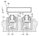
(第1実施形態)
本発明の超音波溶接装置100は、図1に示すように、ここでは二重管式オイルクーラ(図示せず)のオイル出入り口部となるニップル10と、このニップル10をオイルクーラ本体部(図示せず)にろう付けするためのろう材20とを予め接合する溶接装置としており、まず、基本的な構成について説明する。
(First embodiment)
As shown in FIG. 1, an
ここで、ニップル(本発明の第1部材に対応)10は、高力黄銅材から成り、切削加工によって円筒状の本体部11の中間部にフランジ部12が設けられた部材であり、また、ろう材(本発明の第2部材に対応)20は、銅系材から成り、扁平なリング状を成す部材である。
Here, the nipple (corresponding to the first member of the present invention) 10 is a member made of a high-strength brass material and having a flange portion 12 provided in the middle portion of the cylindrical
超音波溶接装置100は、主に受け台110とホーン120とから成る。受け台110は、重ねられたニップル10およびろう材20のうち、ニップル10を支持する支持部111を有する。支持部111は、有底の円筒状を成しており、この支持部111より一回り大きく形成された有底円筒状のケース部112内を図1中の上下方向(受け台110およびホーン120間方向)に摺動可能と成るように収容されている。尚、ケース部112自身は受け台110に固定されている。
The
また、ケース部112(受け台110)と支持部111との間には弾性部材としてのバネ130が介在されており、支持部111を所定力(後述する溶接時の加圧力に相当)でホーン120側に付勢するようにしている。そして、本発明では上記ケース部112およびバネ130を有する支持部111を受け台110に対して複数(ここでは2つ)設けている。
Further, a
一方、ホーン120は、2つの支持部111の配置領域に拡がる平板状(図1は断面表示のため、扁平な四角形状で示している)を成している。ホーン120は、図1中の上下方向に可動し、溶接時には下降して二組のニップル10およびろう材20を共に押下げて、2つのろう材20が共にホーン120に当接するようにすると共に、図示しない超音波振動子からの振動をろう材20に付加する。
On the other hand, the
次に、上記構成に基づく超音波溶接装置100の作動およびその作用効果について説明する。まず、作業者によって支持部111にニップル10がセットされる。これは、支持部111の内部空間にニップル10の本体部11の下側が挿入され、支持部111の開口側にニップル10のフランジ部12が支持されることで成される。そして、ニップル10の本体部11の上側にろう材20が重ねられてセットされる。
Next, the operation of the
その後に、ホーン120が下降し、支持部111を押下げながら、ホーン120に2つのろう材20を共に当接させる。この時、バネ130の付勢力によって、支持部111、ホーン120間でニップル10およびろう材20は加圧されることになる。
Thereafter, the
そして、振動子から発生される超音波振動がホーン120に伝達され、ホーン120は、ろう材20を振動させる。ニップル10とろう材20は、付加される加圧力によって圧縮変形され、振動によって相対的に滑り移動しつつ、当接面で新生凝着することで接合される。
Then, ultrasonic vibration generated from the vibrator is transmitted to the
本発明においては、バネ130によって支持部111が上下方向に摺動可能としているので、ニップル10およびろう材20の重ね方向の寸法バラツキ、あるいは受け台110およびホーン120間の寸法バラツキ等(図1中のh、H寸法のバラツキ)を吸収して、複数組の両部材10、20のすべてを支持部111とホーン120との間に確実に挟持して、均等に加圧させることができるので、複数組の両部材10、20を同時に接合できる。
In the present invention, since the
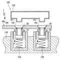
(第2実施形態)
本発明の第2実施形態を図2に示す。第2実施形態は、上記第1実施形態に対して、ろう材20をニップル10にセットする際の位置決め部140を追加したものである。
(Second Embodiment)
A second embodiment of the present invention is shown in FIG. 2nd Embodiment adds the
位置決め部140は、平板状の本体部141に、ニップル10位置に対応するようにすり鉢状の穴部142が設けられたものであり、作業者がニップル10を支持部111にセットした後に、このニップル10の上側に移動配置されるようにしている。そして、作業者はろう材20を位置決め部140の穴部142から挿入するようにしている。
The
一方、ホーン120は、ろう材20側に下降した際に位置決め部140を避けて、ろう材20の上側面にのみ当接するように、凸状部121が形成されている。
On the other hand, the
これにより、ニップル10に対してろう材20を容易に位置決めして、両者10、20を接合することができる。
Thereby, the
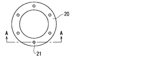
(第3実施形態)
上記第1、第2実施形態におけるろう材20は、オイルクーラ本体へのろう付け用部材であるので、ニップル10に対しては、ろう付けを実施するまでの仮接合として、接合されていれば事足りるものである。よって、仮接合を念頭に置いた場合は、図3、図4に示すように、ろう材20にリング状に均等配置され、ニップル10側に突出する凸部21を複数(ここでは6つ)設けて対応するようにしても良い。
(Third embodiment)
Since the
この場合は、ニップル10とろう材20の当接面における平面度や、受け台110およびホーン120間の平行度等が劣る場合でも、加圧力に相当する付勢力よって片当りする近傍の凸部21を先に潰して、当接面において複数の凸部21を全体的に当接させることができる。よって、バネ130による付勢力を両部材10、20間に均等に付加することができ、確実な仮接合が可能となる。
In this case, even in the case where the flatness at the contact surface between the
尚、上記対応は両部材10、20の材質が異なり、当接面同士の馴染みが悪い場合でも、凸部21における集中的な仮接合が可能となり、好適な手法として用いることができる。
In addition, even if the material of both the
(その他の実施形態)
上記第1〜第3実施形態では、二重管式オイルクーラに用いるニップル10およびろう材20を例にして、両部材10、20を接合するものとして説明したが、2つの部材はこれに限定されるものでは無く、その他の板部材等の種々ものへの対応が可能である。
(Other embodiments)
In the first to third embodiments, the
また、同時に接合する部材同士の組み合わせ数は、2つに限定されるものでは無く、3つ以上としても良い。 Further, the number of combinations of members to be joined simultaneously is not limited to two, and may be three or more.
10 ニップル(第1部材)
20 ろう材(第2部材)
21 凸部
100 超音波溶接装置
110 受け台
111 支持部
120 ホーン
130 バネ(弾性部材)
140 位置決め部
10 Nipple (first member)
20 Brazing material (second member)
21
140 Positioning part
Claims (2)
前記第2部材(20)側から前記第1部材(10)側に加圧力を与えつつ、振動子によって発生される超音波振動を前記第2部材(20)に付加するホーン(120)とを有し、
前記加圧力および前記超音波振動によって前記両部材(10、20)同士を接合する超音波溶接装置において、
前記支持部(111)は、複数設けられると共に、前記受け台(110)および前記ホーン(120)間方向に摺動可能とし、
前記支持部(111)と前記受け台(110)との間には、前記第1部材(10)を介して前記第2部材(20)を前記ホーン(120)に前記加圧力に相当する付勢力で当接させる弾性部材(130)を設け、
前記第1部材(10)に対する前記第2部材(20)の位置決めを行う位置決め部(140)を有し、
前記ホーン(120)は、前記位置決め部(140)を避けて前記第2部材(20)に当接するようにしたことを特徴とする超音波溶接装置。 Of the stacked first member (10) and second member (20), a cradle (110) having a support portion (111) for supporting the first member (10);
A horn (120) that applies ultrasonic vibration generated by a vibrator to the second member (20) while applying pressure from the second member (20) side to the first member (10) side. Have
In the ultrasonic welding apparatus for joining the members (10, 20) to each other by the applied pressure and the ultrasonic vibration,
A plurality of the support portions (111) are provided and slidable in the direction between the cradle (110) and the horn (120),
Between the support portion (111) and the cradle (110), the second member (20) is attached to the horn (120) via the first member (10), corresponding to the applied pressure. An elastic member (130) to be contacted by force is provided ,
A positioning part (140) for positioning the second member (20) relative to the first member (10);
The ultrasonic welding apparatus according to claim 1, wherein the horn (120) is configured to contact the second member (20) while avoiding the positioning portion (140) .
前記両部材(10、20)は、前記凸部(21)によって仮接合されるものとして供給されることを特徴とする請求項1に記載の超音波溶接装置。 On one side (20) of the contact surface between the two members (10, 20), a plurality of convex portions (21) are provided that are uniformly distributed and project to the other side (10),
It said two members (10, 20) are ultrasonic welding apparatus according to claim 1, characterized in that supplied as being temporarily joined by the convex portion (21).
Priority Applications (1)
| Application Number | Priority Date | Filing Date | Title |
|---|---|---|---|
| JP2004027134A JP4293003B2 (en) | 2004-02-03 | 2004-02-03 | Ultrasonic welding equipment |
Applications Claiming Priority (1)
| Application Number | Priority Date | Filing Date | Title |
|---|---|---|---|
| JP2004027134A JP4293003B2 (en) | 2004-02-03 | 2004-02-03 | Ultrasonic welding equipment |
Publications (2)
| Publication Number | Publication Date |
|---|---|
| JP2005219064A JP2005219064A (en) | 2005-08-18 |
| JP4293003B2 true JP4293003B2 (en) | 2009-07-08 |
Family
ID=34995118
Family Applications (1)
| Application Number | Title | Priority Date | Filing Date |
|---|---|---|---|
| JP2004027134A Expired - Fee Related JP4293003B2 (en) | 2004-02-03 | 2004-02-03 | Ultrasonic welding equipment |
Country Status (1)
| Country | Link |
|---|---|
| JP (1) | JP4293003B2 (en) |
Families Citing this family (2)
| Publication number | Priority date | Publication date | Assignee | Title |
|---|---|---|---|---|
| ES2401081T3 (en) * | 2006-05-11 | 2013-04-16 | Indag Gesellschaft für Industriebedarf mbH & Co. Betriebs KG | Ultrasonic welding device |
| JP6934688B2 (en) * | 2016-11-15 | 2021-09-15 | 株式会社キーレックス | Metal parts manufacturing method and metal parts manufacturing equipment |
-
2004
- 2004-02-03 JP JP2004027134A patent/JP4293003B2/en not_active Expired - Fee Related
Also Published As
| Publication number | Publication date |
|---|---|
| JP2005219064A (en) | 2005-08-18 |
Similar Documents
| Publication | Publication Date | Title |
|---|---|---|
| US8950458B2 (en) | System and method for mounting ultrasonic tools | |
| CN101173671A (en) | Centrifugal fan and manufacturing method thereof | |
| JPS6026011B2 (en) | hydraulic acoustic welding machine | |
| JP4293003B2 (en) | Ultrasonic welding equipment | |
| WO2013085942A1 (en) | Linear friction welding method | |
| KR101599987B1 (en) | Ultrasonic welding apparatus | |
| JP2006212692A (en) | Ultrasonic joining method and device therefor | |
| US20040031423A1 (en) | Self-adjusting dynamic floating fixture | |
| JP6413929B2 (en) | Manufacturing method of semiconductor device | |
| JP2018083209A (en) | Ultrasonic bonding equipment | |
| JP2018008294A (en) | Manufacturing method of cylindrical workpiece | |
| JP6957054B1 (en) | Rivet joining method and joining processing equipment | |
| JP6934688B2 (en) | Metal parts manufacturing method and metal parts manufacturing equipment | |
| JP2009178981A (en) | Ultrasonic welding equipment | |
| JP3492298B2 (en) | Ultrasonic vibration bonding tool and supporting device | |
| JP5131963B2 (en) | Vibration welding equipment | |
| JP6641097B2 (en) | Ultrasonic bonding method | |
| JP6739795B2 (en) | Metal component manufacturing method and metal component manufacturing apparatus | |
| JP2006015354A (en) | Ultrasonic welding apparatus, correcting member for ultrasonic welding, and ultrasonic welding method | |
| JP4524639B2 (en) | Ultrasonic bonding method and ultrasonic bonding apparatus | |
| JP2009166260A (en) | Device and method of vibration welding | |
| SE0401340D0 (en) | Stapler | |
| JP2018030172A (en) | Longitudinal vibration welding equipment | |
| JP4572690B2 (en) | Ultrasonic bonding method and ultrasonic bonding apparatus | |
| JP2007230110A (en) | Synthetic resin air pipe |
Legal Events
| Date | Code | Title | Description |
|---|---|---|---|
| A621 | Written request for application examination |
Free format text: JAPANESE INTERMEDIATE CODE: A621 Effective date: 20060417 |
|
| A977 | Report on retrieval |
Free format text: JAPANESE INTERMEDIATE CODE: A971007 Effective date: 20081029 |
|
| A131 | Notification of reasons for refusal |
Free format text: JAPANESE INTERMEDIATE CODE: A131 Effective date: 20081104 |
|
| A521 | Written amendment |
Free format text: JAPANESE INTERMEDIATE CODE: A523 Effective date: 20081222 |
|
| TRDD | Decision of grant or rejection written | ||
| A01 | Written decision to grant a patent or to grant a registration (utility model) |
Free format text: JAPANESE INTERMEDIATE CODE: A01 Effective date: 20090317 |
|
| A01 | Written decision to grant a patent or to grant a registration (utility model) |
Free format text: JAPANESE INTERMEDIATE CODE: A01 |
|
| A61 | First payment of annual fees (during grant procedure) |
Free format text: JAPANESE INTERMEDIATE CODE: A61 Effective date: 20090330 |
|
| FPAY | Renewal fee payment (event date is renewal date of database) |
Free format text: PAYMENT UNTIL: 20120417 Year of fee payment: 3 |
|
| R150 | Certificate of patent or registration of utility model |
Free format text: JAPANESE INTERMEDIATE CODE: R150 |
|
| FPAY | Renewal fee payment (event date is renewal date of database) |
Free format text: PAYMENT UNTIL: 20120417 Year of fee payment: 3 |
|
| FPAY | Renewal fee payment (event date is renewal date of database) |
Free format text: PAYMENT UNTIL: 20130417 Year of fee payment: 4 |
|
| FPAY | Renewal fee payment (event date is renewal date of database) |
Free format text: PAYMENT UNTIL: 20130417 Year of fee payment: 4 |
|
| FPAY | Renewal fee payment (event date is renewal date of database) |
Free format text: PAYMENT UNTIL: 20140417 Year of fee payment: 5 |
|
| R250 | Receipt of annual fees |
Free format text: JAPANESE INTERMEDIATE CODE: R250 |
|
| R250 | Receipt of annual fees |
Free format text: JAPANESE INTERMEDIATE CODE: R250 |
|
| S802 | Written request for registration of partial abandonment of right |
Free format text: JAPANESE INTERMEDIATE CODE: R311802 |
|
| R350 | Written notification of registration of transfer |
Free format text: JAPANESE INTERMEDIATE CODE: R350 |
|
| R250 | Receipt of annual fees |
Free format text: JAPANESE INTERMEDIATE CODE: R250 |
|
| R250 | Receipt of annual fees |
Free format text: JAPANESE INTERMEDIATE CODE: R250 |
|
| LAPS | Cancellation because of no payment of annual fees |