EP1854419B1 - Chirurgisches Instrument mit Kastengelenk und Verfahren zu dessen Herstellung - Google Patents
Chirurgisches Instrument mit Kastengelenk und Verfahren zu dessen Herstellung Download PDFInfo
- Publication number
- EP1854419B1 EP1854419B1 EP07251961A EP07251961A EP1854419B1 EP 1854419 B1 EP1854419 B1 EP 1854419B1 EP 07251961 A EP07251961 A EP 07251961A EP 07251961 A EP07251961 A EP 07251961A EP 1854419 B1 EP1854419 B1 EP 1854419B1
- Authority
- EP
- European Patent Office
- Prior art keywords
- box joint
- pieces
- joint portion
- medical instrument
- male
- Prior art date
- Legal status (The legal status is an assumption and is not a legal conclusion. Google has not performed a legal analysis and makes no representation as to the accuracy of the status listed.)
- Active
Links
Images

Classifications
-
- A—HUMAN NECESSITIES
- A61—MEDICAL OR VETERINARY SCIENCE; HYGIENE
- A61B—DIAGNOSIS; SURGERY; IDENTIFICATION
- A61B17/00—Surgical instruments, devices or methods
- A61B17/28—Surgical forceps
- A61B17/2812—Surgical forceps with a single pivotal connection
- A61B17/2816—Pivots
-
- A—HUMAN NECESSITIES
- A61—MEDICAL OR VETERINARY SCIENCE; HYGIENE
- A61B—DIAGNOSIS; SURGERY; IDENTIFICATION
- A61B17/00—Surgical instruments, devices or methods
- A61B17/28—Surgical forceps
-
- A—HUMAN NECESSITIES
- A61—MEDICAL OR VETERINARY SCIENCE; HYGIENE
- A61B—DIAGNOSIS; SURGERY; IDENTIFICATION
- A61B17/00—Surgical instruments, devices or methods
- A61B17/32—Surgical cutting instruments
- A61B17/3201—Scissors
-
- A—HUMAN NECESSITIES
- A61—MEDICAL OR VETERINARY SCIENCE; HYGIENE
- A61B—DIAGNOSIS; SURGERY; IDENTIFICATION
- A61B17/00—Surgical instruments, devices or methods
- A61B17/28—Surgical forceps
- A61B2017/2808—Clamp, e.g. towel clamp
-
- A—HUMAN NECESSITIES
- A61—MEDICAL OR VETERINARY SCIENCE; HYGIENE
- A61B—DIAGNOSIS; SURGERY; IDENTIFICATION
- A61B17/00—Surgical instruments, devices or methods
- A61B17/28—Surgical forceps
- A61B17/29—Forceps for use in minimally invasive surgery
- A61B2017/2947—Pivots
Definitions
- the present invention relates generally to medical devices. More particularly, the present invention relates to a method of manufacturing a medical instrument having a box joint, and an apparatus corresponding thereto.
- Box joints are a commonly employed coupling and hinge mechanism used in a variety of tools. Included among these tools are various medical instruments, such as a forceps, scissors, or a rongeur.
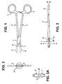
- An example of a box joint used in a medical instrument such as a forceps is shown in FIG. 1 , which depicts a box joint 1 which couples the handle portions 2,3 of two body parts 4,5 of a forceps (the distal operating end portions opposite the handle portions not being shown).
- one body part or half of the device commonly referred to as the "female" portion, includes a channel 10 that is part of the box joint portion mechanism, as shown in FIG. 2 .
- the channel 10 is sized to be just wide enough to accommodate the neck of a complementary male body part or other half of the device, where such neck is arranged to be disposed through the channel 10 so that the two body parts cooperate in a hinge-like manner through the box joint mechanism, as is well known to those skilled in the art.
- the only way to assemble and manufacture a box joint type instrument is to heat the female portion 5 with a suitable heat source, such as, for example, a propane torch, and to then spread the walls 12 and 14 forming the pivot area around channel 10 in the direction of arrows A, and to then insert the male portion 2 through the opening 10 and then hammer the walls 12 and 14 of the female portion 3 back into shape.
- a suitable heat source such as, for example, a propane torch
- the improved method of making a box joint in a medical instrument reduces the costs of manufacture and improves the overall efficiency of the manufacturing process for the medical instrument. It is further desirable to provide an improved method of manufacturing, assembling and finishing a medical device having a box joint where said method will eliminate the need for early assembly of the box joint as elaborated above and will instead allow for better cleaning and polishing of the male and female pivot areas around the box joint portion prior to final assembly of the device.
- US-A-5133724 discloses an abdominal aortic clamp according to the preamble of claim 1 which includes a box junction for connecting the opposing body halves of a scissor type tool.
- This document does not in itself provide any detailed disclosure of the nature of the box junction but refers to the disclosure of US 3952724 , which teaches only a conventional type box junction which would, therefore, require assembly by spreading the walls of the female box junction so as to enable the end of the body half carrying the male box joint part, remote from the handle, to pass through the female box joint.
- This, however, is a conventional type arrangement as discussed previously which therefore suffers from the same problems already discussed above.
- an apparatus in some embodiments provides an improved method of manufacturing, assembling and finishing a medical device having a box joint where said method will eliminate the need for early assembly of the box joint and will instead allow for better cleaning and polishing of the male and female pivot areas around the box joint portion prior to final assembly of the device.
- a medical instrument comprising: a first half-body and a second half-body joined by a box joint, the first half-body having a female box joint portion defining a channel for accommodating a male box joint portion in the second half body, the second half-body being formed by at least two pieces including a first piece and a second piece, characterised in that: each piece has a complementary mating means for rigidly coupling the two pieces together, the first piece incorporating the male box joint portion, and in that the region of the first piece encompassing the male box joint portion, the mating means and the region therebetween is sized to fit through the channel of the female box joint portion, wherein the instrument is formed by inserting the male box joint portion and mating means of the first piece of the second half-body through the channel in the first half-body and then rigidly joining the first and second pieces of the second half-body by permanently coupling the complementary mating means on the first and second pieces.
- the present invention further provides a method of assembling a medical instrument having a box joint, comprising: forming the parts of a medical instrument according to the invention; inserting the male box joint portion through the channel in the female box joint portion; and coupling the complementary mating means of the second half-body to join the first and second pieces to form the second half-body.
- An embodiment in accordance with the present invention provides a medical forceps having an improved method of manufacture thereof.
- the method of the present invention includes a method of forming, assembling and manufacturing a medical tool, such as a medical forceps, which has a box joint, the method eliminating the need for initial assembly of the box joint through spreading apart the sidewalls of the female box joint portion.
- the present invention thereby allows for better cleaning and polishing of the male and female pivot areas around the box joint portion prior to final assembly of the device.
- FIG. 1 shows a plan view of a medical instrument, such as a forceps, having a box joint.
- a box joint is well-known to those of ordinary skill in the art.
- the box joint 1 shown in FIG. 1 joins two pieces of the tool, which are referred to herein as a "half-body.”
- the tool can include a first "male" half-body 2 and a second "female" half-body 3, which are conjoined at the box joint portion 1.
- Each of the male and female half-bodies 2 and 3 can have handle portions 4 and 5 at their proximal ends.
- proximal or proximal end shall refer to the specified end of a device or its component which is generally closer to the medical personnel handling or manipulating the device as it is intended to be used, and the term “distal” or “distal end” shall refer to the specified end of a device or its component which is opposite the proximal end.
- the medical instrument therefore includes distal first and second operating end portions 6 and 7.
- Each of the first and second operating end portions 6 and 7 can have any of a variety of well-known distal extensions 8 and 9, respectively, which are shown in FIG. 1 as dotted lines so that the scope of the present invention is understood to include any medical instrument having any distal operating end, such as, for example, a forceps.
- FIG. 2 is a top view showing the female portion of the medical instrument illustrated in FIG 1 .
- the box joint portion 1 is shown with the male half-body's neck portion 10 which fits between the two sidewalls 12 and 14 that make up the female portion of the box joint defined by the female half-body 3.
- the two sidewalls 12 and 14 therefore define a channel into which the male neck portion 10 fits to produce a snug box joint interconnection.
- Conventional assembly of such a box joint involves the initial spreading apart of the two sidewalls 12 and 14 in the direction of arrows "A" shown in FIG. 2 , after which the male half-body 2 is then inserted between the two sidewalls 12 and 14 which are then reformed and straightened to close the box joint.
- FIG. 3 is a front view of the medical instrument shown in FIG. 1.
- FIG. 3A is an enlarged front view of the area A around the box joint of the medical instrument shown in FIG. 3 .
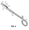
- FIG. 4 is a perspective view of a female portion or half-body 20 of a medical instrument in one embodiment of the present invention.
- the female half-body 20 includes a female box joint portion 22 interposed between a proximal handle portion 24 and a distal operating end portion 26 (extreme distal tip not shown).
- a channel 30 is shown between the two sidewalls 32 and 34 of the female box joint portion 22.
- FIG. 5 is a perspective view of two portions which form the male portion or second half-body 40 of the medical instrument according to the present invention.
- the second half-body 40 includes two pieces, a second proximal handle portion 42 of the medical instrument, and a male box joint portion 44 having a distal operating end portion 46 (extreme distal tip not shown).
- the male box joint portion 44 includes a neck portion 50 which can generally be a narrow, thin planar element configured to snugly fit within the channel 30 defined by the female box joint portion 22.
- the male box joint portion 44 is complementary to the female box joint portion 22 so as to form a properly interconnected and operating box joint for the medical instrument.
- the male box joint portion 44 also includes a first mating end portion 52.
- Mating end 52 is shown in the embodiment in FIG. 5 as a finger-like extension or protrusion on the proximal end of the male box joint portion 44, extending from the planar neck portion 50.
- Mating end 52 is configured and shaped to fit into a corresponding and complementary second mating end 54 defined at the distal end of the handle portion 42 of the male half-body 40.
- Complementary second mating end 54 is defined in the embodiment shown in FIG. 5 as a narrow slot 56 into which the finger-like protrusion 52 can fit. Interconnection of the two complementary mating ends 52 and 54 can thereby couple the two pieces 42 and 44 of the male half-body.
- a medical device having a box joint is assembled by first making or machining the male portion 40 of the instrument in two pieces 42 and 44, such as shown in FIG. 5 , as well as the female half-body 20 as shown in FIG. 4 .
- the surface areas of both the male and female pieces and elements can be cleaned and polished properly and easily before assembly, especially around the critical box joint portions.
- the instrument can then be assembled by sliding the male box joint portion 44 through the channel 30 of the female box joint portion 22. Then the slot 56 in the male handle portion 42 can be aligned to the corresponding protrusion 52 on the male box joint portion 44, and both parts 42 and 44 can be permanently coupled together.
- Such coupling can be performed in a myriad of ways, but, in a preferred embodiment, can be accomplished by resistance welding. Resistance welding can be much stronger than laser welding or some other form of welding, because the three surfaces on the protrusion 52 which are in apposition with the corresponding surfaces of slot 56 will be completely welded together providing a stronger bonded joint.
- the method of the present invention therefore would allow for very intricate distal tips on the instrument to be precision investment cast, regardless of the volumes, at a very cost effective rate.
- the complementary mating means made up of elements 52 and 54,56 of the embodiment shown in FIG. 5 are but one form of mating and coupling the two pieces 42 and 44 of the male half-body 40, and that any number of alternative mating means can be incorporated into the present invention.
Landscapes
- Health & Medical Sciences (AREA)
- Surgery (AREA)
- Life Sciences & Earth Sciences (AREA)
- Medical Informatics (AREA)
- Nuclear Medicine, Radiotherapy & Molecular Imaging (AREA)
- Engineering & Computer Science (AREA)
- Biomedical Technology (AREA)
- Heart & Thoracic Surgery (AREA)
- Ophthalmology & Optometry (AREA)
- Molecular Biology (AREA)
- Animal Behavior & Ethology (AREA)
- General Health & Medical Sciences (AREA)
- Public Health (AREA)
- Veterinary Medicine (AREA)
- Surgical Instruments (AREA)
- Lining Or Joining Of Plastics Or The Like (AREA)
Claims (7)
- Medizinisches Instrument, das umfasst:einen ersten Halbkörper (20) und einen zweiten Halbkörper (40), die durch ein Kastengelenk (box joint) (22, 44) verbunden sind,wobei der erste Halbköper (20) einen Aufnahme-Kastengelenkabschnitt (22) hat, der eine Rinne (30) zum Aufnehmen eines Einführ-Kastengelenkabschnitts (44) in dem zweiten Halbkörper (40) aufweist,und der zweite Halbkörper (40) durch wenigstens zwei Einzelteile (42, 46) gebildet wird, die ein erstes Einzelteil (46) sowie ein zweites Einzelteil (42) enthalten,dadurch gekennzeichnet, dass:jedes Einzelteil (42, 46) des zweiten Halbkörpers (40) eine komplementäre Eingriffseinrichtung (42, 54, 56) zum starren Verbinden der zwei Einzelteile miteinander hat, das erste Einzelteil (46) den Einführ-Kastengelenkabschnitt (44) enthält, und dass der Bereich des ersten Einzelteils (46), der den Einführ-Kastengelenkabschnitt (44), die Eingriffseinrichtung (52) und den Bereich dazwischen umschließt, so bemessen ist, dass er durch die Rinne (30) des Aufnahme-Kastengelenkabschnitts (22) hindurch passt, wobei das Instrument ausgebildet wird, indem der Einführ-Kastengelenkab-schnitt (44) und die Eingriffseinrichtung (52) des ersten Einzelteils (46) des zweiten Halbkörpers durch den Kanal (30) in dem ersten Halbkörper (20) eingeführt werden und dann das erste (46) und das zweite (42) Einzelteil des zweiten Halbkörpers (40) starr zusammengefügt werden, indem die komplementären Eingriffseinrichtungen (52, 54, 56) an dem ersten und dem zweiten Einzelteil (46, 42) fest verbunden werden.
- Medizinisches Instrument nach Anspruch 1, wobei die Eingriffseinrichtungen (52, 54, 56) an einem der wenigstens zwei Einzeleile (42, 46) ein längliches vorstehendes Element (52) enthalten und das längliche vorstehende Element (52) so geformt ist, dass es in einen entsprechenden Schlitz (56) passt, den die Eingriffseinrichtung in einem anderen der wenigstens zwei Einzelteile (44) aufweist.
- Medizinisches Instrument nach Anspruch 1 oder 2, wobei das erste (46) und das zweite (42) Einzelteil des zweiten Halbkörpers zusammengefügt werden, indem die komplementären Eingriffseinrichtungen an dem ersten und dem zweiten Einzelteil durch Widerstandsschweißen fest verbunden werden.
- Medizinisches Instrument nach einem der vorangehenden Ansprüche, wobei die erste Eingriffseinrichtung einen länglichen Vorsprung umfasst, der so eingerichtet ist, dass er in einen entsprechenden Schlitz passt, der durch die zweite Eingriffseinrichtung in dem zweiten Griffabschnitt gebildet wird.
- Medizinisches Instrument nach einem der vorangehenden Ansprüche, wobei das medizinische Instrument eine Zange ist.
- Verfahren zum Zusammensetzen eines medizinischen Instrumentes mit einem Kastengelenk (1), das umfasst:Ausbilden der Einzelteile eines medizinischen Instruments nach einem der vorangehenden Ansprüche;Einführen des Einführ-Kastengelenkabschnitts (44) durch die Rinne (33) in dem Aufnahme-Kastengelenkabschnitt (22); undVerbinden der komplementären Eingriffseinrichtungen (52, 54, 56) des zweiten Halbkörpers (40), um das erste und das zweite Einzelteil (46, 42) zusammenzufügen und den zweiten Halbkörper (40) auszubilden.
- Verfahren nach Anspruch 6, wobei der Schritt des Verbindens der ersten komplementären Eingriffseinrichtungen (52, 54, 56) zum Zusammenfügen des ersten (46) und des zweiten (42) Einzelteils des zweiten Halbkörpers (40) Widerstandsschweißen umfasst.
Applications Claiming Priority (1)
| Application Number | Priority Date | Filing Date | Title |
|---|---|---|---|
| US11/431,481 US20070265657A1 (en) | 2006-05-11 | 2006-05-11 | Box joint medical tool apparatus and method of manufacture |
Publications (2)
| Publication Number | Publication Date |
|---|---|
| EP1854419A1 EP1854419A1 (de) | 2007-11-14 |
| EP1854419B1 true EP1854419B1 (de) | 2009-01-07 |
Family
ID=38294085
Family Applications (1)
| Application Number | Title | Priority Date | Filing Date |
|---|---|---|---|
| EP07251961A Active EP1854419B1 (de) | 2006-05-11 | 2007-05-11 | Chirurgisches Instrument mit Kastengelenk und Verfahren zu dessen Herstellung |
Country Status (4)
| Country | Link |
|---|---|
| US (1) | US20070265657A1 (de) |
| EP (1) | EP1854419B1 (de) |
| AT (1) | ATE419799T1 (de) |
| DE (1) | DE602007000448D1 (de) |
Families Citing this family (5)
| Publication number | Priority date | Publication date | Assignee | Title |
|---|---|---|---|---|
| US7351248B2 (en) * | 2002-03-25 | 2008-04-01 | Tri-State Hospital Supply Corporation | Surgical instrument with snag free box hinge |
| US20070112376A1 (en) * | 2005-11-14 | 2007-05-17 | Tri-State Hospital Supply Corporation | Medical tubing clamping apparatus |
| DE102017105706A1 (de) * | 2017-03-16 | 2018-09-20 | Aesculap Ag | Additiv hergestelltes medizintechnisches Instrument sowie Verfahren zur Herstellung eines solchen Instruments |
| DE102019106512A1 (de) * | 2019-03-14 | 2020-09-17 | Aesculap Ag | Chirurgisches Instrument mit durchströmbarem Schlussbereich |
| CN111388256A (zh) * | 2020-03-27 | 2020-07-10 | 广东省人民医院(广东省医学科学院) | 一种单人操作多方向调节手固定装置 |
Family Cites Families (6)
| Publication number | Priority date | Publication date | Assignee | Title |
|---|---|---|---|---|
| US3952749A (en) * | 1974-05-15 | 1976-04-27 | Pilling Co. | Box lock surgical instrument |
| US3911766A (en) * | 1974-05-15 | 1975-10-14 | Pilling Co | Box lock surgical instrument and method of its manufacture |
| US3952724A (en) * | 1974-06-24 | 1976-04-27 | Owens-Illinois, Inc. | Solar energy converter |
| US4823792A (en) * | 1987-05-11 | 1989-04-25 | Andrew Tool Company | Gripping device and locking mechanism for use therewith |
| US5133724A (en) * | 1991-04-04 | 1992-07-28 | Pilling Co. | Abdominal aortic clamp |
| US5906621A (en) * | 1996-05-14 | 1999-05-25 | United States Endoscopy Group, Inc. | Endoscopic surgical device |
-
2006
- 2006-05-11 US US11/431,481 patent/US20070265657A1/en not_active Abandoned
-
2007
- 2007-05-11 EP EP07251961A patent/EP1854419B1/de active Active
- 2007-05-11 DE DE602007000448T patent/DE602007000448D1/de active Active
- 2007-05-11 AT AT07251961T patent/ATE419799T1/de not_active IP Right Cessation
Also Published As
| Publication number | Publication date |
|---|---|
| US20070265657A1 (en) | 2007-11-15 |
| ATE419799T1 (de) | 2009-01-15 |
| EP1854419A1 (de) | 2007-11-14 |
| DE602007000448D1 (de) | 2009-02-26 |
Similar Documents
| Publication | Publication Date | Title |
|---|---|---|
| CA2035375C (en) | Coupling device and method | |
| JP2938486B2 (ja) | 湾曲管およびその製造方法 | |
| EP1854419A1 (de) | Chirurgisches Instrument mit Kastengelenk und Verfahren zu dessen herstellung | |
| US5507331A (en) | Drilling/cutting bit, and method of making joint | |
| EP1250891A3 (de) | Chirurgisches Instrument | |
| JP7654703B2 (ja) | 付加製造によって製造される医療器具 | |
| ATE463319T1 (de) | Werkzeugkupplung für rotationswerkzeug | |
| JPH0716677A (ja) | 押出し部材と相手部材との接合構造および接合方法 | |
| HK1203446A1 (en) | Hand tool joint | |
| AU2019332787B2 (en) | Surgical tool attachment devices, systems, and methods | |
| US12331532B2 (en) | Hand tool and method of construction | |
| JP4436503B2 (ja) | 内視鏡 | |
| US3717921A (en) | Manufacture of scissors, tongs, pliers or the like cutting or gripping tools | |
| JP2009261587A (ja) | 内視鏡湾曲管とその製造方法及び内視鏡 | |
| JP2005230182A (ja) | 湾曲装置、湾曲装置の製造方法、及びカテーテル | |
| JP4161170B2 (ja) | 分割型シャシーフレームおよびその製造方法 | |
| ITMI20011481A1 (it) | Procedimento per la piegatura di lamiere e articolo prodotto piegandolamiere | |
| JP3750684B2 (ja) | T型分岐管継手 | |
| JP2000271133A (ja) | 内視鏡用鉗子 | |
| JP2023508497A (ja) | ツーピースのクリップアプライヤージョー組立体及び製造方法 | |
| EP1995546A1 (de) | Verfahren zur Herstellung eines Radiators und Radiator | |
| JP2021049066A (ja) | 鋏の開閉機構 | |
| KR20010036428A (ko) | 딥 브레이징을 위한 도파관 구조 | |
| TWM560380U (zh) | 花紋鋼刀之組合構造 | |
| JPH0539684Y2 (de) |
Legal Events
| Date | Code | Title | Description |
|---|---|---|---|
| PUAI | Public reference made under article 153(3) epc to a published international application that has entered the european phase |
Free format text: ORIGINAL CODE: 0009012 |
|
| AK | Designated contracting states |
Kind code of ref document: A1 Designated state(s): AT BE BG CH CY CZ DE DK EE ES FI FR GB GR HU IE IS IT LI LT LU LV MC MT NL PL PT RO SE SI SK TR |
|
| AX | Request for extension of the european patent |
Extension state: AL BA HR MK YU |
|
| 17P | Request for examination filed |
Effective date: 20071220 |
|
| GRAP | Despatch of communication of intention to grant a patent |
Free format text: ORIGINAL CODE: EPIDOSNIGR1 |
|
| AKX | Designation fees paid |
Designated state(s): AT BE BG CH CY CZ DE DK EE ES FI FR GB GR HU IE IS IT LI LT LU LV MC MT NL PL PT RO SE SI SK TR |
|
| GRAS | Grant fee paid |
Free format text: ORIGINAL CODE: EPIDOSNIGR3 |
|
| GRAA | (expected) grant |
Free format text: ORIGINAL CODE: 0009210 |
|
| AK | Designated contracting states |
Kind code of ref document: B1 Designated state(s): AT BE BG CH CY CZ DE DK EE ES FI FR GB GR HU IE IS IT LI LT LU LV MC MT NL PL PT RO SE SI SK TR |
|
| REG | Reference to a national code |
Ref country code: GB Ref legal event code: FG4D |
|
| REG | Reference to a national code |
Ref country code: CH Ref legal event code: EP |
|
| REG | Reference to a national code |
Ref country code: IE Ref legal event code: FG4D |
|
| REF | Corresponds to: |
Ref document number: 602007000448 Country of ref document: DE Date of ref document: 20090226 Kind code of ref document: P |
|
| PG25 | Lapsed in a contracting state [announced via postgrant information from national office to epo] |
Ref country code: NL Free format text: LAPSE BECAUSE OF FAILURE TO SUBMIT A TRANSLATION OF THE DESCRIPTION OR TO PAY THE FEE WITHIN THE PRESCRIBED TIME-LIMIT Effective date: 20090107 Ref country code: SI Free format text: LAPSE BECAUSE OF FAILURE TO SUBMIT A TRANSLATION OF THE DESCRIPTION OR TO PAY THE FEE WITHIN THE PRESCRIBED TIME-LIMIT Effective date: 20090107 |
|
| NLV1 | Nl: lapsed or annulled due to failure to fulfill the requirements of art. 29p and 29m of the patents act | ||
| PG25 | Lapsed in a contracting state [announced via postgrant information from national office to epo] |
Ref country code: ES Free format text: LAPSE BECAUSE OF FAILURE TO SUBMIT A TRANSLATION OF THE DESCRIPTION OR TO PAY THE FEE WITHIN THE PRESCRIBED TIME-LIMIT Effective date: 20090418 Ref country code: LT Free format text: LAPSE BECAUSE OF FAILURE TO SUBMIT A TRANSLATION OF THE DESCRIPTION OR TO PAY THE FEE WITHIN THE PRESCRIBED TIME-LIMIT Effective date: 20090107 Ref country code: FI Free format text: LAPSE BECAUSE OF FAILURE TO SUBMIT A TRANSLATION OF THE DESCRIPTION OR TO PAY THE FEE WITHIN THE PRESCRIBED TIME-LIMIT Effective date: 20090107 |
|
| PG25 | Lapsed in a contracting state [announced via postgrant information from national office to epo] |
Ref country code: IS Free format text: LAPSE BECAUSE OF FAILURE TO SUBMIT A TRANSLATION OF THE DESCRIPTION OR TO PAY THE FEE WITHIN THE PRESCRIBED TIME-LIMIT Effective date: 20090507 Ref country code: AT Free format text: LAPSE BECAUSE OF FAILURE TO SUBMIT A TRANSLATION OF THE DESCRIPTION OR TO PAY THE FEE WITHIN THE PRESCRIBED TIME-LIMIT Effective date: 20090107 Ref country code: LV Free format text: LAPSE BECAUSE OF FAILURE TO SUBMIT A TRANSLATION OF THE DESCRIPTION OR TO PAY THE FEE WITHIN THE PRESCRIBED TIME-LIMIT Effective date: 20090107 Ref country code: PT Free format text: LAPSE BECAUSE OF FAILURE TO SUBMIT A TRANSLATION OF THE DESCRIPTION OR TO PAY THE FEE WITHIN THE PRESCRIBED TIME-LIMIT Effective date: 20090608 Ref country code: SE Free format text: LAPSE BECAUSE OF FAILURE TO SUBMIT A TRANSLATION OF THE DESCRIPTION OR TO PAY THE FEE WITHIN THE PRESCRIBED TIME-LIMIT Effective date: 20090407 Ref country code: PL Free format text: LAPSE BECAUSE OF FAILURE TO SUBMIT A TRANSLATION OF THE DESCRIPTION OR TO PAY THE FEE WITHIN THE PRESCRIBED TIME-LIMIT Effective date: 20090107 |
|
| PG25 | Lapsed in a contracting state [announced via postgrant information from national office to epo] |
Ref country code: BE Free format text: LAPSE BECAUSE OF FAILURE TO SUBMIT A TRANSLATION OF THE DESCRIPTION OR TO PAY THE FEE WITHIN THE PRESCRIBED TIME-LIMIT Effective date: 20090107 |
|
| PG25 | Lapsed in a contracting state [announced via postgrant information from national office to epo] |
Ref country code: DK Free format text: LAPSE BECAUSE OF FAILURE TO SUBMIT A TRANSLATION OF THE DESCRIPTION OR TO PAY THE FEE WITHIN THE PRESCRIBED TIME-LIMIT Effective date: 20090107 Ref country code: CZ Free format text: LAPSE BECAUSE OF FAILURE TO SUBMIT A TRANSLATION OF THE DESCRIPTION OR TO PAY THE FEE WITHIN THE PRESCRIBED TIME-LIMIT Effective date: 20090107 Ref country code: EE Free format text: LAPSE BECAUSE OF FAILURE TO SUBMIT A TRANSLATION OF THE DESCRIPTION OR TO PAY THE FEE WITHIN THE PRESCRIBED TIME-LIMIT Effective date: 20090107 |
|
| PLBE | No opposition filed within time limit |
Free format text: ORIGINAL CODE: 0009261 |
|
| STAA | Information on the status of an ep patent application or granted ep patent |
Free format text: STATUS: NO OPPOSITION FILED WITHIN TIME LIMIT |
|
| PG25 | Lapsed in a contracting state [announced via postgrant information from national office to epo] |
Ref country code: RO Free format text: LAPSE BECAUSE OF FAILURE TO SUBMIT A TRANSLATION OF THE DESCRIPTION OR TO PAY THE FEE WITHIN THE PRESCRIBED TIME-LIMIT Effective date: 20090107 Ref country code: SK Free format text: LAPSE BECAUSE OF FAILURE TO SUBMIT A TRANSLATION OF THE DESCRIPTION OR TO PAY THE FEE WITHIN THE PRESCRIBED TIME-LIMIT Effective date: 20090107 |
|
| 26N | No opposition filed |
Effective date: 20091008 |
|
| PG25 | Lapsed in a contracting state [announced via postgrant information from national office to epo] |
Ref country code: MC Free format text: LAPSE BECAUSE OF NON-PAYMENT OF DUE FEES Effective date: 20090531 |
|
| PG25 | Lapsed in a contracting state [announced via postgrant information from national office to epo] |
Ref country code: BG Free format text: LAPSE BECAUSE OF FAILURE TO SUBMIT A TRANSLATION OF THE DESCRIPTION OR TO PAY THE FEE WITHIN THE PRESCRIBED TIME-LIMIT Effective date: 20090407 |
|
| REG | Reference to a national code |
Ref country code: FR Ref legal event code: ST Effective date: 20100129 |
|
| PG25 | Lapsed in a contracting state [announced via postgrant information from national office to epo] |
Ref country code: FR Free format text: LAPSE BECAUSE OF NON-PAYMENT OF DUE FEES Effective date: 20090602 Ref country code: IE Free format text: LAPSE BECAUSE OF NON-PAYMENT OF DUE FEES Effective date: 20090511 |
|
| PG25 | Lapsed in a contracting state [announced via postgrant information from national office to epo] |
Ref country code: GR Free format text: LAPSE BECAUSE OF FAILURE TO SUBMIT A TRANSLATION OF THE DESCRIPTION OR TO PAY THE FEE WITHIN THE PRESCRIBED TIME-LIMIT Effective date: 20090408 |
|
| PG25 | Lapsed in a contracting state [announced via postgrant information from national office to epo] |
Ref country code: IT Free format text: LAPSE BECAUSE OF FAILURE TO SUBMIT A TRANSLATION OF THE DESCRIPTION OR TO PAY THE FEE WITHIN THE PRESCRIBED TIME-LIMIT Effective date: 20090107 |
|
| PG25 | Lapsed in a contracting state [announced via postgrant information from national office to epo] |
Ref country code: LU Free format text: LAPSE BECAUSE OF NON-PAYMENT OF DUE FEES Effective date: 20090511 |
|
| PG25 | Lapsed in a contracting state [announced via postgrant information from national office to epo] |
Ref country code: HU Free format text: LAPSE BECAUSE OF FAILURE TO SUBMIT A TRANSLATION OF THE DESCRIPTION OR TO PAY THE FEE WITHIN THE PRESCRIBED TIME-LIMIT Effective date: 20090708 |
|
| PG25 | Lapsed in a contracting state [announced via postgrant information from national office to epo] |
Ref country code: TR Free format text: LAPSE BECAUSE OF FAILURE TO SUBMIT A TRANSLATION OF THE DESCRIPTION OR TO PAY THE FEE WITHIN THE PRESCRIBED TIME-LIMIT Effective date: 20090107 |
|
| PG25 | Lapsed in a contracting state [announced via postgrant information from national office to epo] |
Ref country code: CY Free format text: LAPSE BECAUSE OF FAILURE TO SUBMIT A TRANSLATION OF THE DESCRIPTION OR TO PAY THE FEE WITHIN THE PRESCRIBED TIME-LIMIT Effective date: 20090107 |
|
| REG | Reference to a national code |
Ref country code: CH Ref legal event code: PL |
|
| PG25 | Lapsed in a contracting state [announced via postgrant information from national office to epo] |
Ref country code: LI Free format text: LAPSE BECAUSE OF NON-PAYMENT OF DUE FEES Effective date: 20110531 Ref country code: CH Free format text: LAPSE BECAUSE OF NON-PAYMENT OF DUE FEES Effective date: 20110531 |
|
| PGFP | Annual fee paid to national office [announced via postgrant information from national office to epo] |
Ref country code: DE Payment date: 20130729 Year of fee payment: 7 |
|
| PGFP | Annual fee paid to national office [announced via postgrant information from national office to epo] |
Ref country code: GB Payment date: 20130729 Year of fee payment: 7 |
|
| REG | Reference to a national code |
Ref country code: GB Ref legal event code: 732E Free format text: REGISTERED BETWEEN 20140116 AND 20140122 |
|
| REG | Reference to a national code |
Ref country code: DE Ref legal event code: R081 Ref document number: 602007000448 Country of ref document: DE Owner name: TECOMET INC., US Free format text: FORMER OWNER: TELEFLEX MEDICAL INC., LIMERICK, US Effective date: 20140116 Ref country code: DE Ref legal event code: R081 Ref document number: 602007000448 Country of ref document: DE Owner name: TECOMET INC., WILMINGTON, US Free format text: FORMER OWNER: TELEFLEX MEDICAL INC., LIMERICK, PA., US Effective date: 20140116 |
|
| REG | Reference to a national code |
Ref country code: DE Ref legal event code: R119 Ref document number: 602007000448 Country of ref document: DE |
|
| GBPC | Gb: european patent ceased through non-payment of renewal fee |
Effective date: 20140511 |
|
| REG | Reference to a national code |
Ref country code: DE Ref legal event code: R119 Ref document number: 602007000448 Country of ref document: DE Effective date: 20141202 |
|
| PG25 | Lapsed in a contracting state [announced via postgrant information from national office to epo] |
Ref country code: DE Free format text: LAPSE BECAUSE OF NON-PAYMENT OF DUE FEES Effective date: 20141202 |
|
| PG25 | Lapsed in a contracting state [announced via postgrant information from national office to epo] |
Ref country code: GB Free format text: LAPSE BECAUSE OF NON-PAYMENT OF DUE FEES Effective date: 20140511 |