EP1853800B1 - Wabenkörper mit zerklüfteten stirnseiten - Google Patents
Wabenkörper mit zerklüfteten stirnseiten Download PDFInfo
- Publication number
- EP1853800B1 EP1853800B1 EP06707217A EP06707217A EP1853800B1 EP 1853800 B1 EP1853800 B1 EP 1853800B1 EP 06707217 A EP06707217 A EP 06707217A EP 06707217 A EP06707217 A EP 06707217A EP 1853800 B1 EP1853800 B1 EP 1853800B1
- Authority
- EP
- European Patent Office
- Prior art keywords
- honeycomb body
- end side
- metal sheets
- cutouts
- ducts
- Prior art date
- Legal status (The legal status is an assumption and is not a legal conclusion. Google has not performed a legal analysis and makes no representation as to the accuracy of the status listed.)
- Not-in-force
Links
Images
Classifications
-
- F—MECHANICAL ENGINEERING; LIGHTING; HEATING; WEAPONS; BLASTING
- F01—MACHINES OR ENGINES IN GENERAL; ENGINE PLANTS IN GENERAL; STEAM ENGINES
- F01N—GAS-FLOW SILENCERS OR EXHAUST APPARATUS FOR MACHINES OR ENGINES IN GENERAL; GAS-FLOW SILENCERS OR EXHAUST APPARATUS FOR INTERNAL-COMBUSTION ENGINES
- F01N3/00—Exhaust or silencing apparatus having means for purifying, rendering innocuous, or otherwise treating exhaust
- F01N3/02—Exhaust or silencing apparatus having means for purifying, rendering innocuous, or otherwise treating exhaust for cooling, or for removing solid constituents of, exhaust
- F01N3/021—Exhaust or silencing apparatus having means for purifying, rendering innocuous, or otherwise treating exhaust for cooling, or for removing solid constituents of, exhaust by means of filters
- F01N3/022—Exhaust or silencing apparatus having means for purifying, rendering innocuous, or otherwise treating exhaust for cooling, or for removing solid constituents of, exhaust by means of filters characterised by specially adapted filtering structure, e.g. honeycomb, mesh or fibrous
- F01N3/0222—Exhaust or silencing apparatus having means for purifying, rendering innocuous, or otherwise treating exhaust for cooling, or for removing solid constituents of, exhaust by means of filters characterised by specially adapted filtering structure, e.g. honeycomb, mesh or fibrous the structure being monolithic, e.g. honeycombs
-
- B—PERFORMING OPERATIONS; TRANSPORTING
- B01—PHYSICAL OR CHEMICAL PROCESSES OR APPARATUS IN GENERAL
- B01J—CHEMICAL OR PHYSICAL PROCESSES, e.g. CATALYSIS OR COLLOID CHEMISTRY; THEIR RELEVANT APPARATUS
- B01J35/00—Catalysts, in general, characterised by their form or physical properties
- B01J35/50—Catalysts, in general, characterised by their form or physical properties characterised by their shape or configuration
- B01J35/56—Foraminous structures having flow-through passages or channels, e.g. grids or three-dimensional monoliths
- B01J35/57—Honeycombs
-
- F—MECHANICAL ENGINEERING; LIGHTING; HEATING; WEAPONS; BLASTING
- F01—MACHINES OR ENGINES IN GENERAL; ENGINE PLANTS IN GENERAL; STEAM ENGINES
- F01N—GAS-FLOW SILENCERS OR EXHAUST APPARATUS FOR MACHINES OR ENGINES IN GENERAL; GAS-FLOW SILENCERS OR EXHAUST APPARATUS FOR INTERNAL-COMBUSTION ENGINES
- F01N3/00—Exhaust or silencing apparatus having means for purifying, rendering innocuous, or otherwise treating exhaust
- F01N3/08—Exhaust or silencing apparatus having means for purifying, rendering innocuous, or otherwise treating exhaust for rendering innocuous
- F01N3/10—Exhaust or silencing apparatus having means for purifying, rendering innocuous, or otherwise treating exhaust for rendering innocuous by thermal or catalytic conversion of noxious components of exhaust
- F01N3/24—Exhaust or silencing apparatus having means for purifying, rendering innocuous, or otherwise treating exhaust for rendering innocuous by thermal or catalytic conversion of noxious components of exhaust characterised by constructional aspects of converting apparatus
- F01N3/28—Construction of catalytic reactors
- F01N3/2803—Construction of catalytic reactors characterised by structure, by material or by manufacturing of catalyst support
- F01N3/2807—Metal other than sintered metal
- F01N3/281—Metallic honeycomb monoliths made of stacked or rolled sheets, foils or plates
-
- F—MECHANICAL ENGINEERING; LIGHTING; HEATING; WEAPONS; BLASTING
- F01—MACHINES OR ENGINES IN GENERAL; ENGINE PLANTS IN GENERAL; STEAM ENGINES
- F01N—GAS-FLOW SILENCERS OR EXHAUST APPARATUS FOR MACHINES OR ENGINES IN GENERAL; GAS-FLOW SILENCERS OR EXHAUST APPARATUS FOR INTERNAL-COMBUSTION ENGINES
- F01N2330/00—Structure of catalyst support or particle filter
- F01N2330/02—Metallic plates or honeycombs, e.g. superposed or rolled-up corrugated or otherwise deformed sheet metal
-
- F—MECHANICAL ENGINEERING; LIGHTING; HEATING; WEAPONS; BLASTING
- F01—MACHINES OR ENGINES IN GENERAL; ENGINE PLANTS IN GENERAL; STEAM ENGINES
- F01N—GAS-FLOW SILENCERS OR EXHAUST APPARATUS FOR MACHINES OR ENGINES IN GENERAL; GAS-FLOW SILENCERS OR EXHAUST APPARATUS FOR INTERNAL-COMBUSTION ENGINES
- F01N2330/00—Structure of catalyst support or particle filter
- F01N2330/30—Honeycomb supports characterised by their structural details
- F01N2330/32—Honeycomb supports characterised by their structural details characterised by the shape, form or number of corrugations of plates, sheets or foils
-
- Y—GENERAL TAGGING OF NEW TECHNOLOGICAL DEVELOPMENTS; GENERAL TAGGING OF CROSS-SECTIONAL TECHNOLOGIES SPANNING OVER SEVERAL SECTIONS OF THE IPC; TECHNICAL SUBJECTS COVERED BY FORMER USPC CROSS-REFERENCE ART COLLECTIONS [XRACs] AND DIGESTS
- Y02—TECHNOLOGIES OR APPLICATIONS FOR MITIGATION OR ADAPTATION AGAINST CLIMATE CHANGE
- Y02T—CLIMATE CHANGE MITIGATION TECHNOLOGIES RELATED TO TRANSPORTATION
- Y02T10/00—Road transport of goods or passengers
- Y02T10/10—Internal combustion engine [ICE] based vehicles
- Y02T10/12—Improving ICE efficiencies
-
- Y—GENERAL TAGGING OF NEW TECHNOLOGICAL DEVELOPMENTS; GENERAL TAGGING OF CROSS-SECTIONAL TECHNOLOGIES SPANNING OVER SEVERAL SECTIONS OF THE IPC; TECHNICAL SUBJECTS COVERED BY FORMER USPC CROSS-REFERENCE ART COLLECTIONS [XRACs] AND DIGESTS
- Y10—TECHNICAL SUBJECTS COVERED BY FORMER USPC
- Y10S—TECHNICAL SUBJECTS COVERED BY FORMER USPC CROSS-REFERENCE ART COLLECTIONS [XRACs] AND DIGESTS
- Y10S55/00—Gas separation
- Y10S55/30—Exhaust treatment
-
- Y—GENERAL TAGGING OF NEW TECHNOLOGICAL DEVELOPMENTS; GENERAL TAGGING OF CROSS-SECTIONAL TECHNOLOGIES SPANNING OVER SEVERAL SECTIONS OF THE IPC; TECHNICAL SUBJECTS COVERED BY FORMER USPC CROSS-REFERENCE ART COLLECTIONS [XRACs] AND DIGESTS
- Y10—TECHNICAL SUBJECTS COVERED BY FORMER USPC
- Y10T—TECHNICAL SUBJECTS COVERED BY FORMER US CLASSIFICATION
- Y10T428/00—Stock material or miscellaneous articles
- Y10T428/12—All metal or with adjacent metals
- Y10T428/1234—Honeycomb, or with grain orientation or elongated elements in defined angular relationship in respective components [e.g., parallel, inter- secting, etc.]
-
- Y—GENERAL TAGGING OF NEW TECHNOLOGICAL DEVELOPMENTS; GENERAL TAGGING OF CROSS-SECTIONAL TECHNOLOGIES SPANNING OVER SEVERAL SECTIONS OF THE IPC; TECHNICAL SUBJECTS COVERED BY FORMER USPC CROSS-REFERENCE ART COLLECTIONS [XRACs] AND DIGESTS
- Y10—TECHNICAL SUBJECTS COVERED BY FORMER USPC
- Y10T—TECHNICAL SUBJECTS COVERED BY FORMER US CLASSIFICATION
- Y10T428/00—Stock material or miscellaneous articles
- Y10T428/24—Structurally defined web or sheet [e.g., overall dimension, etc.]
- Y10T428/24149—Honeycomb-like
Definitions
- the present invention relates to a metallic honeycomb body, in particular for the purification of exhaust gas of an internal combustion engine.
- a special field of application is the purification of an exhaust gas from particles.
- An early design for which the DE 29 02 779 A1 typical examples shows is the spiral design, in which substantially a smooth and a corrugated sheet are superimposed and spirally wound.
- the honeycomb body is constructed of a plurality of alternately arranged smooth and corrugated or differently corrugated sheets, wherein the sheets first form one or more stacks, which are entwined with each other.
- the ends of all sheets come to lie outside and can be connected to a housing or casing tube, whereby numerous connections arise, which increase the durability of the honeycomb body.
- Typical examples of these designs are in EP 0 245 737 B1 or the WO 90/03220 described. It has also long been known to provide the sheets with additional structures in order to influence the flow and / or to achieve a cross-mixing between the individual flow channels. Typical examples of such embodiments are the WO 91/01178 , the WO 91/01807 and the WO 90/08249 , Finally, there are also honeycomb bodies in a conical design, possibly also with additional additional structures for flow control. Such a honeycomb body is for example in the WO 97/49905 described. Moreover, it is also known to release a recess for a sensor in a honeycomb body, in particular for accommodating a lambda probe. An example of this is in the DE 88 16 154 U1 described.
- honeycomb bodies have a multiplicity of at least partially structured sheet-metal layers whose structuring forms channels which originate from an entry surface lead to an exit surface of the honeycomb body.
- sheet metal layers the successive layers of the honeycomb body are meant, regardless of whether these sheet metal layers consist of one or more separate sheets. It should be noted that it is in principle possible to build a honeycomb body from only a single sheet by z. B. a part of the metal strip corrugated and the remaining smooth part of the metal strip is folded by bending it. The resulting structure can be spirally wound from the bending line to a honeycomb body. The next option is to use a smooth and a corrugated sheet to make a spirally wound honeycomb. Also multi-start spirals of three or more sheets are possible.
- honeycomb bodies contain a plurality of sheets, but the number of sheets and the number of superimposed sheet metal layers also need not necessarily be the same. For this reason, a distinction in principle between a sheet and a sheet-metal layer, even if this is often not possible, for example, in drawings showing only a section of a honeycomb body.
- honeycomb bodies in an exhaust gas stream which contains soot particles, can become clogged completely or partially by deposited soot particles. This impairs the regular function, in particular as a soot filter, and / or makes regeneration more difficult.
- Object of the present invention is therefore to provide a honeycomb body in which there is a reduced probability of deposition of soot particles on the end faces.
- soot particles on the front side of a honeycomb body are perpendicular to the flow direction. Soot particles bounce almost exactly perpendicular to the end faces of the honeycomb body. By creating a rugged structure at the entrance end, two things are achieved simultaneously. On the one hand are already geometrically now considerable parts of the end face of the honeycomb body no longer exactly perpendicular to the flow direction, on the other hand, the course of the flow at. Entry into the individual channels influenced so that only a few particles can strike the frontal face on the front. In addition, any resulting soot deposits are already partially in the interior of the channels, so that a catalytic reaction can be easily initiated by contact with catalytically coated channel walls in motion. Any resulting deposits can therefore be easily removed again.
- An inventive honeycomb body is therefore wound from sheets, looped and / or layered with a plurality of at least partially structured Sheet metal layers whose structuring forms channels that lead from an inlet end face to an exit end face of the honeycomb body.
- at least a part of the sheet-metal layers at the inlet end face or at the inlet end side and the outlet end side has recesses at their edges, so that a fissured structure of the inlet end side and exit front side results.
- honeycomb bodies are constructed of alternating layers of substantially smooth and corrugated sheets, it being possible according to the invention that only the smooth sheets, only the corrugated sheets or both have recesses.
- honeycomb bodies which are designed as particle filters, in particular for removing soot particles
- a part of the sheet metal layers consists of porous material, in particular of compacted metal fibers.
- sheets can therefore also consist of porous material, in particular fiber material.
- the invention is applicable to virtually all known metallic honeycomb bodies, which are constructed from one or more sheets, regardless of which additional openings, structures or other special features such honeycomb body.
- metallic honeycomb bodies which are constructed from sheet metal layers, often soldered at their ends, that is, the metallic sheet metal layers are soldered together at the front end at their points of contact.
- the problem naturally arises here of course that conventional methods for soldering the sheet metal layers together can not be readily applied.
- it is advantageous, as indicated in one embodiment of the invention, not to provide the sheets on their front sides everywhere with recesses, but to provide at their front edges sections without recesses that are long enough and often enough that statistically distributed always a large number of contact points between the foremost and the rearmost Edges of the sheet metal layers results.
- the compound is applied to honeycomb bodies formed of one or more stacks of sheets, the sheets of each stack having a predetermined length and width, the length being greater than the width, and the sheets of each stack being respectively many Have recesses over the length.
- the recesses are thus located on the longitudinal sides of the sheets, while the broadsides are preferably, but not necessarily, formed without recesses. Since the broadsides typically have to be connected to the jacket tube during the completion of a honeycomb body, recesses are not necessarily advantageous here.
- the recesses have rounded boundary lines, whereby notch effects, ie the tearing of the sheet metal edges in the region of the recesses, are largely avoided.
- Recesses in the form of Kreisabschnüten preferably in each case a semicircle or smaller circular section are particularly preferred.
- particle filter z. B. also be made of perforated sheet metal layers, where appropriate, even the machines with which holes are produced in the sheet metal layers anyway, can also be used to produce the recesses at the edges of the sheet metal layers. It is even possible to evenly provide wide metal strips with holes and then to snow the metal strips to the desired width, wherein preferably the cutting lines should run through the middle of rows of holes.
- a honeycomb body which has at least one cavity at the inlet end face.
- This cavity is preferably arranged centrically and in particular has a conically tapering section.
- honeycomb body in which a part of the channels is closed near the exit end face.
- closure of the channels may be accomplished by squeezing the channel walls and / or providing a blockage.
- at least part of the channels arranged on the outer edge of the honeycomb body are closed, so that a forced flow within the honeycomb body through the recesses passes into internal partial volumes.
- this has a plurality of sub-volumes which have a mutually different number of channels per unit cross-sectional area.
- a coaxial arrangement (for example for cylindrical configurations of the honeycomb body) of two partial volumes is preferred.
- honeycomb bodies according to the invention is primarily the cleaning of the exhaust gas of internal combustion engines, in particular diesel engines, in particular, the elimination of soot particles from the exhaust gas is in the foreground here.
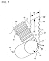
- Fig. 1 shows a honeycomb body 1 schematically during the manufacturing process.
- the honeycomb body 1 is constructed from a structured sheet 2 and a smooth sheet 3, wherein the structured sheet 2 has recesses 9 at both longitudinal edges. Even the smooth sheet 3 with the width B and the length L has at its front edges 8 over the length L many recesses 10.
- the boundary lines 12 of these recesses 10 are rounded, so that the recesses 10 have approximately the shape of circle segments.
- the channels 4 of the honeycomb body 1 wherein despite the recesses 9, 10 still enough frontal connection points 11 between the smooth and corrugated sheet metal layers 2, 3 arise.
- the finished honeycomb body later has a fissured inlet end face 5 and a jagged exit end face 6, but still enough solder joints 11 can be soldered together by conventional methods if required.
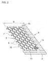
- Fig. 2 shows a suitable for building a honeycomb according to the invention corrugated sheet 2 with the width B.
- the entrance end face 5 recesses 9 while the exit end face 6 has an edge strip 15 without recesses.
- the front edge 7 of the corrugated sheet 2 has recesses 9 with Vietnameseabismef'örmigen boundary lines 12.
- Also inside the structured sheet 2 openings 13 are present.
- the exact shape of the openings 13 and recesses 9 is not important, but it may be advantageous to choose the shapes so that the projection of these openings or recesses on the center plane of the structured sheet 2 circular or circular section is.
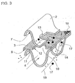
- Fig. 3 shows a schematic perspective view of the typical conditions in a particulate filter in which the exhaust gas is deflected by deflection structures 14 through a porous smooth layer 3 of metal fibers 16.
- the flow paths 19 are indicated by arrows.
- soot particles 17 are directed to the porous sheet-metal layer 3, held there and implemented.
- the accumulation of soot particles 17 can be reduced to the frontal sheet edge 7 of the structured sheet 2 or the frontal sheet edge 8 of the smooth sheet 3 by recesses 10 in the smooth sheet 3.
- the boundary line 12 of the recess 10 has approximately the shape of a circular section. you recognizes that the recess 10 influences the flow conditions as the flow enters the adjacent channels 4 and thus accumulation of particles is less likely.
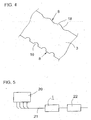
- Fig. 4 shows schematically various ways of designing the edges of a sheet with recesses.
- an end-side sheet edge 8 of the smooth sheet 3 is provided with individual recesses 10, while the opposite sheet edge has the shape of a wavy line 18.
- a wavy line 18 should be considered in the context of the present invention as a sheet edge with recesses.
- FIG Fig. 5 A typical installation situation of a honeycomb body 1 according to the invention is shown in FIG Fig. 5 shown. From an internal combustion engine 20, exhaust gases pass into an exhaust system 21, which has the honeycomb body 1 according to the invention and optionally further components, in particular a downstream oxidation catalyst 22.
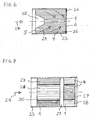
- Fig. 6 shows a, placed in a housing 23, honeycomb body 1, which has a centrally disposed cavity 25 at the inlet end face 5.
- This cavity 25 has a conically tapered portion.
- the ducts 4 of different lengths due to the cavity 25 cause pressure differences, so that the exhaust gas arriving with the illustrated flow direction 24 is deflected in the interior of the honeycomb body, as shown diagrammatically by the arrows.
- a part of the channels 4 close to the exit end face 6 is closed by means of an annular blockage 26.
- honeycomb bodies 1 are shown in a housing 23, each having two concentric partial volumes 27, 28, which have a different number of channels 4 per unit cross-sectional area.
- the honeycomb body 1 with a gap 29, for example, less than 10 mm from each other spaced and have an inverse arrangement of the partial volumes 27, 28, so that the partial volume 27 with a high channel density of the first honeycomb body with the partial volume 28 with lower channel density of the second honeycomb body are opposite (as seen in the flow direction 24).
- the variant shown is preferred in which the first honeycomb body has a first part volume 27 with a high channel density on the outside.
- the first subvolume 27 has a channel density which is at least a factor of 1.5 greater than that of the second subvolume 28.
- the first subvolume has a channel density in the range of at least 800 cpsi (cells per square inch; 6.4516 cells per square centimeter).
- this support member 30 may be, for example, a pipe section.
- the present invention serves to further improve metallic honeycomb bodies when used as exhaust gas purification components, in particular for the removal of pollutant particles from an exhaust gas.
- the invention prevents or reduces the deposition of particles, in particular soot, on the end faces of a honeycomb body.
Landscapes
- Chemical & Material Sciences (AREA)
- Engineering & Computer Science (AREA)
- Chemical Kinetics & Catalysis (AREA)
- Mechanical Engineering (AREA)
- General Engineering & Computer Science (AREA)
- Combustion & Propulsion (AREA)
- Toxicology (AREA)
- Health & Medical Sciences (AREA)
- Materials Engineering (AREA)
- Organic Chemistry (AREA)
- Filtering Of Dispersed Particles In Gases (AREA)
- Exhaust Gas After Treatment (AREA)
- Processes For Solid Components From Exhaust (AREA)
- Filtering Materials (AREA)
Priority Applications (2)
| Application Number | Priority Date | Filing Date | Title |
|---|---|---|---|
| PL06707217T PL1853800T3 (pl) | 2005-02-28 | 2006-02-23 | Element o strukturze plastra miodu ze stronami czołowymi o strukturze szczelinowatej |
| EP08022397A EP2058482A1 (de) | 2005-02-28 | 2006-02-23 | Wabenkörper mit zerklüfteten Stirnseiten |
Applications Claiming Priority (2)
| Application Number | Priority Date | Filing Date | Title |
|---|---|---|---|
| DE102005009585A DE102005009585A1 (de) | 2005-02-28 | 2005-02-28 | Wabenkörper mit zerklüfteten Stirnseiten |
| PCT/EP2006/001670 WO2006092238A1 (de) | 2005-02-28 | 2006-02-23 | Wabenkörper mit zerklüfteten stirnseiten |
Related Child Applications (1)
| Application Number | Title | Priority Date | Filing Date |
|---|---|---|---|
| EP08022397A Division EP2058482A1 (de) | 2005-02-28 | 2006-02-23 | Wabenkörper mit zerklüfteten Stirnseiten |
Publications (2)
| Publication Number | Publication Date |
|---|---|
| EP1853800A1 EP1853800A1 (de) | 2007-11-14 |
| EP1853800B1 true EP1853800B1 (de) | 2009-08-12 |
Family
ID=36143253
Family Applications (2)
| Application Number | Title | Priority Date | Filing Date |
|---|---|---|---|
| EP06707217A Not-in-force EP1853800B1 (de) | 2005-02-28 | 2006-02-23 | Wabenkörper mit zerklüfteten stirnseiten |
| EP08022397A Withdrawn EP2058482A1 (de) | 2005-02-28 | 2006-02-23 | Wabenkörper mit zerklüfteten Stirnseiten |
Family Applications After (1)
| Application Number | Title | Priority Date | Filing Date |
|---|---|---|---|
| EP08022397A Withdrawn EP2058482A1 (de) | 2005-02-28 | 2006-02-23 | Wabenkörper mit zerklüfteten Stirnseiten |
Country Status (9)
| Country | Link |
|---|---|
| US (1) | US7527666B2 (cg-RX-API-DMAC7.html) |
| EP (2) | EP1853800B1 (cg-RX-API-DMAC7.html) |
| JP (1) | JP2008531264A (cg-RX-API-DMAC7.html) |
| KR (1) | KR20070108262A (cg-RX-API-DMAC7.html) |
| CN (1) | CN101128655B (cg-RX-API-DMAC7.html) |
| DE (2) | DE102005009585A1 (cg-RX-API-DMAC7.html) |
| PL (1) | PL1853800T3 (cg-RX-API-DMAC7.html) |
| RU (1) | RU2407898C2 (cg-RX-API-DMAC7.html) |
| WO (1) | WO2006092238A1 (cg-RX-API-DMAC7.html) |
Families Citing this family (13)
| Publication number | Priority date | Publication date | Assignee | Title |
|---|---|---|---|---|
| DE102004001419A1 (de) * | 2003-05-30 | 2004-12-16 | Emitec Gesellschaft Für Emissionstechnologie Mbh | Herstellung eines strukturierten Bleches für Abgasbehandlungseinrichtungen |
| JP5219308B2 (ja) * | 2007-07-13 | 2013-06-26 | ナムローゼ・フエンノートシャップ・ベカート・ソシエテ・アノニム | フィルタ要素 |
| WO2009071636A1 (de) * | 2007-12-07 | 2009-06-11 | Mann+Hummel Gmbh | Filtereinrichtung zur filtration gasförmiger fluide |
| DE102008025593A1 (de) * | 2008-05-28 | 2009-12-03 | Emitec Gesellschaft Für Emissionstechnologie Mbh | Metallischer Wabenkörper mit definierten Verbindungsstellen |
| US20100050874A1 (en) * | 2008-08-29 | 2010-03-04 | Walter Cullen Lucas | Exhaust after treatment system and method |
| JP2013244437A (ja) * | 2012-05-24 | 2013-12-09 | Toyota Motor Corp | 触媒コンバーター |
| JP6206102B2 (ja) * | 2013-11-07 | 2017-10-04 | トヨタ自動車株式会社 | 触媒コンバーター |
| CN104763493B (zh) * | 2014-01-08 | 2019-03-05 | 瑞德(新乡)路业有限公司 | 一种汽车尾气颗粒物捕集器及滤芯 |
| US11389769B2 (en) | 2015-10-30 | 2022-07-19 | Corning Incorported | Porous ceramic filters and methods for making the same |
| JP6562861B2 (ja) * | 2016-03-25 | 2019-08-21 | 日本碍子株式会社 | ハニカム構造体 |
| DE102017207151A1 (de) | 2017-04-27 | 2018-10-31 | Continental Automotive Gmbh | Metallischer Wabenkörper mit haftungsverbessernden Mikrostrukturen |
| WO2019089806A1 (en) * | 2017-10-31 | 2019-05-09 | Corning Incorporated | Honeycomb body and particulate filter comprising a honeycomb body |
| US11751422B2 (en) * | 2018-03-28 | 2023-09-05 | Sharp Kabushiki Kaisha | Display device and method for manufacturing display device |
Family Cites Families (30)
| Publication number | Priority date | Publication date | Assignee | Title |
|---|---|---|---|---|
| DE2902779C2 (de) | 1979-01-25 | 1985-09-26 | Süddeutsche Kühlerfabrik Julius Fr. Behr GmbH & Co. KG, 7000 Stuttgart | Matrix für einen katalytischen Reaktor zur Abgasreinigung bei Brennkraftmaschinen |
| ES2010687B3 (es) | 1986-05-12 | 1989-12-01 | Interatom Ges Mit Beschrankter Haftung | Cuerpo alveolado metalico, especialmente cuerpo portante de catalizador con pared portante y procedimiento para su fabricacion. |
| DE3760479D1 (en) | 1986-05-12 | 1989-09-28 | Interatom | Honeycomb body, particularly a catalyst carrier, provided with opposedly folded metal sheet layers, and its manufacturing process |
| BR8907458A (pt) | 1988-09-22 | 1991-04-02 | Emitec Emissionstechnologie | Corpo alveolar,especialmente corpo de suporte de catalisador,constituido de uma multiplicidade de pilhas de chapa entrelacadas |
| DE8812762U1 (de) * | 1988-10-11 | 1989-06-29 | Emitec Gesellschaft für Emissionstechnologie mbH, 5204 Lohmar | Katalysator mit Doppelmantelsystem |
| DE8816154U1 (de) | 1988-12-29 | 1989-02-09 | Süddeutsche Kühlerfabrik Julius Fr. Behr GmbH & Co KG, 7000 Stuttgart | Trägerkörper für einen katalytischen Reaktor zur Abgasreinigung |
| DE8900467U1 (de) | 1989-01-17 | 1990-05-17 | Emitec Gesellschaft für Emissionstechnologie mbH, 5204 Lohmar | Metallischer Wabenkörper, vorzugsweise Katalysator-Trägerkörper mit Mikrostrukturen zur Strömungsdurchmischung |
| US5403559A (en) | 1989-07-18 | 1995-04-04 | Emitec Gesellschaft Fuer Emissionstechnologie | Device for cleaning exhaust gases of motor vehicles |
| DE8908738U1 (de) | 1989-07-18 | 1989-09-07 | Emitec Gesellschaft für Emissionstechnologie mbH, 5204 Lohmar | Wabenkörper mit internen Strömungsleitflächen, insbesondere Katalysatorkörper für Kraftfahrzeuge |
| DE8909128U1 (de) | 1989-07-27 | 1990-11-29 | Emitec Gesellschaft für Emissionstechnologie mbH, 5204 Lohmar | Wabenkörper mit internen Anströmkanten, insbesondere Katalysatorkörper für Kraftfahrzeuge |
| DE4234930A1 (de) * | 1992-10-16 | 1994-04-21 | Schwaebische Huettenwerke Gmbh | Filter zum Abscheiden von Verunreinigungen aus Abgasen |
| US5599509A (en) * | 1993-03-17 | 1997-02-04 | Nippondenso Co., Ltd. | Honeycomb body and catalyst converter having catalyst carrier configured of this honeycomb |
| JPH08103664A (ja) | 1994-10-04 | 1996-04-23 | Nippondenso Co Ltd | ハニカム体およびこのハニカム体よりなる触媒担体を有する触媒コンバータ |
| JPH06320014A (ja) * | 1993-03-17 | 1994-11-22 | Nippondenso Co Ltd | メタル担体 |
| JPH08177473A (ja) * | 1994-12-22 | 1996-07-09 | Nippon Soken Inc | 排ガス浄化装置 |
| DE19530853A1 (de) * | 1995-08-22 | 1997-02-27 | Emitec Emissionstechnologie | Verfahren zum Herstellen eines Wabenkörpers aus zwei unterschiedlich aufgebauten Metallblecharten |
| JP3813234B2 (ja) * | 1996-03-11 | 2006-08-23 | 日新製鋼株式会社 | 多孔体製の電気抵抗ヒータ |
| JP3434117B2 (ja) * | 1996-03-29 | 2003-08-04 | 住友電気工業株式会社 | ディーゼルエンジン用パティキュレートトラップ |
| DE29611143U1 (de) | 1996-06-25 | 1996-09-12 | Emitec Gesellschaft für Emissionstechnologie mbH, 53797 Lohmar | Konischer Wabenkörper mit Longitudinalstrukturen |
| JP3347593B2 (ja) * | 1996-07-25 | 2002-11-20 | トヨタ自動車株式会社 | ディーゼルエンジン用パティキュレートトラップ |
| DE19823469A1 (de) * | 1998-05-26 | 1999-12-02 | Emitec Emissionstechnologie | Monolithischer metallischer Wabenkörper mit variierender Kanalzahl |
| US6776814B2 (en) * | 2000-03-09 | 2004-08-17 | Fleetguard, Inc. | Dual section exhaust aftertreatment filter and method |
| JP3619469B2 (ja) * | 2001-01-18 | 2005-02-09 | 福寿工業株式会社 | 積層型メタル担体 |
| US6544310B2 (en) * | 2001-05-24 | 2003-04-08 | Fleetguard, Inc. | Exhaust aftertreatment filter with particulate distribution pattern |
| JP3710732B2 (ja) * | 2001-07-26 | 2005-10-26 | 福寿工業株式会社 | 排ガス浄化用金属触媒担体 |
| DE10235766A1 (de) * | 2002-08-02 | 2004-02-19 | Emitec Gesellschaft Für Emissionstechnologie Mbh | Abgasfilter und Verfahren zum Reinigen eines Abgases |
| CN1177128C (zh) * | 2002-10-15 | 2004-11-24 | 上海交通大学 | 基于球弧蜂窝板的汽车尾气催化器 |
| DE10257113A1 (de) * | 2002-12-05 | 2004-06-24 | Emitec Gesellschaft Für Emissionstechnologie Mbh | Partikelfalle mit beschichteter Faserlage |
| JP3543969B1 (ja) * | 2003-06-05 | 2004-07-21 | 株式会社オーデン | 金属フィルタ及び該金属フィルタを備える黒煙微粒子除去装置並びにディーゼル車 |
| JP2007216165A (ja) * | 2006-02-17 | 2007-08-30 | Ngk Insulators Ltd | ハニカムフィルタ |
-
2005
- 2005-02-28 DE DE102005009585A patent/DE102005009585A1/de not_active Withdrawn
-
2006
- 2006-02-23 CN CN2006800063269A patent/CN101128655B/zh not_active Expired - Fee Related
- 2006-02-23 WO PCT/EP2006/001670 patent/WO2006092238A1/de not_active Ceased
- 2006-02-23 DE DE502006004511T patent/DE502006004511D1/de active Active
- 2006-02-23 EP EP06707217A patent/EP1853800B1/de not_active Not-in-force
- 2006-02-23 RU RU2007135793/06A patent/RU2407898C2/ru not_active IP Right Cessation
- 2006-02-23 JP JP2007557384A patent/JP2008531264A/ja active Pending
- 2006-02-23 EP EP08022397A patent/EP2058482A1/de not_active Withdrawn
- 2006-02-23 PL PL06707217T patent/PL1853800T3/pl unknown
- 2006-02-23 KR KR1020077022088A patent/KR20070108262A/ko not_active Ceased
-
2007
- 2007-08-28 US US11/845,799 patent/US7527666B2/en not_active Expired - Fee Related
Also Published As
| Publication number | Publication date |
|---|---|
| KR20070108262A (ko) | 2007-11-08 |
| JP2008531264A (ja) | 2008-08-14 |
| PL1853800T3 (pl) | 2010-03-31 |
| US7527666B2 (en) | 2009-05-05 |
| DE502006004511D1 (de) | 2009-09-24 |
| EP1853800A1 (de) | 2007-11-14 |
| CN101128655A (zh) | 2008-02-20 |
| DE102005009585A1 (de) | 2006-08-31 |
| RU2407898C2 (ru) | 2010-12-27 |
| CN101128655B (zh) | 2012-03-28 |
| RU2007135793A (ru) | 2009-04-10 |
| EP2058482A1 (de) | 2009-05-13 |
| WO2006092238A1 (de) | 2006-09-08 |
| US20080083214A1 (en) | 2008-04-10 |
Similar Documents
| Publication | Publication Date | Title |
|---|---|---|
| EP1853800B1 (de) | Wabenkörper mit zerklüfteten stirnseiten | |
| WO2007134897A1 (de) | Filtereinrichtung, insbesondere für ein abgassystem einer brennkraftmaschine | |
| EP0542775A1 (de) | Monolithischer metallischer wabenkörper mit variierender kanalzahl. | |
| DE20117873U1 (de) | Offener Filterkörper mit verbesserten Strömungseigenschaften | |
| EP2411638B1 (de) | Wabenkörper für ein abgasreinigungssystem | |
| EP1848534B1 (de) | Wabenkörper mit internen kavernen | |
| EP1527262B1 (de) | Abgasfilter und verfahren zum reinigen eines abgases | |
| EP0330161B1 (de) | Verfahren zur Herstellung eines Russpartikelfilters | |
| EP1522686A2 (de) | Abgasreinigungsanordnung | |
| EP1753520B1 (de) | Reinigungseinsatz für abgasreinigungsanlagen, insbesondere für partikelfilter | |
| EP2864604B1 (de) | Konischer wabenkörper mit schräg radial nach aussen verlaufenden kanälen | |
| DE112017006597B4 (de) | Poröser Wabenfilter | |
| EP1559882B1 (de) | Abgasreinigungsanordnung und Verfahren zur Herstellung einer Abgasreinigungsanordnung | |
| EP1431528B1 (de) | Abgasreinigungsanordnung | |
| EP1787705A1 (de) | Filtereinrichtung, insbesondere für ein Abgassystem einer Dieselbrennkraftmaschine | |
| DE102006021737B4 (de) | Filterelement für einen Rußpartikelfilter einer Brennkraftmaschine | |
| EP2219758A1 (de) | Filterelement zur filterung von abgasen einer brennkraftmaschine | |
| DE102006016890A1 (de) | Filtereinrichtung, insbesondere für ein Abgassystem einer Brennkraftmaschine | |
| DE102005055073A1 (de) | Filterelement und Filter zur Abgasnachbehandlung | |
| EP2122132A1 (de) | Dieselpartikelfilter-bauteil | |
| DE102006019048A1 (de) | Filtereinrichtung, insbesondere für ein Abgassystem einer Brennkraftmaschine | |
| DE102006021298A1 (de) | Filtereinrichtung, insbesondere für ein Abgassystem einer Brennkraftmaschine | |
| DE102005044765A1 (de) | Filterelement und Filter zur Abgasnachbehandlung | |
| DE102006020725A1 (de) | Filtereinrichtung, insbesondere für ein Abgassystem einer Brennkraftmaschine |
Legal Events
| Date | Code | Title | Description |
|---|---|---|---|
| PUAI | Public reference made under article 153(3) epc to a published international application that has entered the european phase |
Free format text: ORIGINAL CODE: 0009012 |
|
| 17P | Request for examination filed |
Effective date: 20070803 |
|
| AK | Designated contracting states |
Kind code of ref document: A1 Designated state(s): DE ES FR GB IT PL |
|
| 17Q | First examination report despatched |
Effective date: 20071227 |
|
| R17C | First examination report despatched (corrected) |
Effective date: 20080111 |
|
| DAX | Request for extension of the european patent (deleted) | ||
| RBV | Designated contracting states (corrected) |
Designated state(s): DE ES FR GB IT PL |
|
| GRAP | Despatch of communication of intention to grant a patent |
Free format text: ORIGINAL CODE: EPIDOSNIGR1 |
|
| GRAS | Grant fee paid |
Free format text: ORIGINAL CODE: EPIDOSNIGR3 |
|
| GRAA | (expected) grant |
Free format text: ORIGINAL CODE: 0009210 |
|
| AK | Designated contracting states |
Kind code of ref document: B1 Designated state(s): DE ES FR GB IT PL |
|
| REG | Reference to a national code |
Ref country code: GB Ref legal event code: FG4D Free format text: NOT ENGLISH |
|
| REF | Corresponds to: |
Ref document number: 502006004511 Country of ref document: DE Date of ref document: 20090924 Kind code of ref document: P |
|
| PG25 | Lapsed in a contracting state [announced via postgrant information from national office to epo] |
Ref country code: ES Free format text: LAPSE BECAUSE OF FAILURE TO SUBMIT A TRANSLATION OF THE DESCRIPTION OR TO PAY THE FEE WITHIN THE PRESCRIBED TIME-LIMIT Effective date: 20091123 |
|
| REG | Reference to a national code |
Ref country code: PL Ref legal event code: T3 |
|
| PLBE | No opposition filed within time limit |
Free format text: ORIGINAL CODE: 0009261 |
|
| STAA | Information on the status of an ep patent application or granted ep patent |
Free format text: STATUS: NO OPPOSITION FILED WITHIN TIME LIMIT |
|
| 26N | No opposition filed |
Effective date: 20100517 |
|
| GBPC | Gb: european patent ceased through non-payment of renewal fee |
Effective date: 20100223 |
|
| PG25 | Lapsed in a contracting state [announced via postgrant information from national office to epo] |
Ref country code: GB Free format text: LAPSE BECAUSE OF NON-PAYMENT OF DUE FEES Effective date: 20100223 |
|
| PGFP | Annual fee paid to national office [announced via postgrant information from national office to epo] |
Ref country code: PL Payment date: 20110118 Year of fee payment: 6 |
|
| PGFP | Annual fee paid to national office [announced via postgrant information from national office to epo] |
Ref country code: FR Payment date: 20120229 Year of fee payment: 7 |
|
| PGFP | Annual fee paid to national office [announced via postgrant information from national office to epo] |
Ref country code: DE Payment date: 20120312 Year of fee payment: 7 |
|
| PGFP | Annual fee paid to national office [announced via postgrant information from national office to epo] |
Ref country code: IT Payment date: 20120224 Year of fee payment: 7 |
|
| REG | Reference to a national code |
Ref country code: FR Ref legal event code: ST Effective date: 20131031 |
|
| REG | Reference to a national code |
Ref country code: DE Ref legal event code: R119 Ref document number: 502006004511 Country of ref document: DE Effective date: 20130903 |
|
| PG25 | Lapsed in a contracting state [announced via postgrant information from national office to epo] |
Ref country code: IT Free format text: LAPSE BECAUSE OF NON-PAYMENT OF DUE FEES Effective date: 20130223 |
|
| PG25 | Lapsed in a contracting state [announced via postgrant information from national office to epo] |
Ref country code: FR Free format text: LAPSE BECAUSE OF NON-PAYMENT OF DUE FEES Effective date: 20130228 Ref country code: DE Free format text: LAPSE BECAUSE OF NON-PAYMENT OF DUE FEES Effective date: 20130903 |
|
| PG25 | Lapsed in a contracting state [announced via postgrant information from national office to epo] |
Ref country code: PL Free format text: LAPSE BECAUSE OF NON-PAYMENT OF DUE FEES Effective date: 20130223 |
|
| REG | Reference to a national code |
Ref country code: PL Ref legal event code: LAPE |