EP1852684B1 - Positionsmesseinrichtung - Google Patents
Positionsmesseinrichtung Download PDFInfo
- Publication number
- EP1852684B1 EP1852684B1 EP07007787A EP07007787A EP1852684B1 EP 1852684 B1 EP1852684 B1 EP 1852684B1 EP 07007787 A EP07007787 A EP 07007787A EP 07007787 A EP07007787 A EP 07007787A EP 1852684 B1 EP1852684 B1 EP 1852684B1
- Authority
- EP
- European Patent Office
- Prior art keywords
- measuring device
- light source
- detector
- position measuring
- carrier substrate
- Prior art date
- Legal status (The legal status is an assumption and is not a legal conclusion. Google has not performed a legal analysis and makes no representation as to the accuracy of the status listed.)
- Not-in-force
Links
- 239000000758 substrate Substances 0.000 claims description 59
- 230000003287 optical effect Effects 0.000 claims description 56
- 238000001514 detection method Methods 0.000 claims description 42
- 230000005540 biological transmission Effects 0.000 claims description 26
- 239000000463 material Substances 0.000 claims description 18
- 239000004020 conductor Substances 0.000 claims description 11
- 230000001419 dependent effect Effects 0.000 claims description 9
- 239000011521 glass Substances 0.000 claims description 6
- 230000000694 effects Effects 0.000 claims description 5
- 230000005855 radiation Effects 0.000 claims description 4
- 230000000737 periodic effect Effects 0.000 description 7
- 238000004519 manufacturing process Methods 0.000 description 4
- 238000005070 sampling Methods 0.000 description 4
- 238000003491 array Methods 0.000 description 2
- 230000000712 assembly Effects 0.000 description 2
- 238000000429 assembly Methods 0.000 description 2
- 238000006073 displacement reaction Methods 0.000 description 2
- 238000005259 measurement Methods 0.000 description 2
- 238000000034 method Methods 0.000 description 2
- 229910000831 Steel Inorganic materials 0.000 description 1
- 230000004075 alteration Effects 0.000 description 1
- 230000008859 change Effects 0.000 description 1
- 239000011248 coating agent Substances 0.000 description 1
- 238000000576 coating method Methods 0.000 description 1
- 150000001875 compounds Chemical class 0.000 description 1
- 230000010354 integration Effects 0.000 description 1
- 230000003993 interaction Effects 0.000 description 1
- 238000004382 potting Methods 0.000 description 1
- 239000010959 steel Substances 0.000 description 1
Images


Classifications
-
- G—PHYSICS
- G01—MEASURING; TESTING
- G01D—MEASURING NOT SPECIALLY ADAPTED FOR A SPECIFIC VARIABLE; ARRANGEMENTS FOR MEASURING TWO OR MORE VARIABLES NOT COVERED IN A SINGLE OTHER SUBCLASS; TARIFF METERING APPARATUS; MEASURING OR TESTING NOT OTHERWISE PROVIDED FOR
- G01D5/00—Mechanical means for transferring the output of a sensing member; Means for converting the output of a sensing member to another variable where the form or nature of the sensing member does not constrain the means for converting; Transducers not specially adapted for a specific variable
- G01D5/26—Mechanical means for transferring the output of a sensing member; Means for converting the output of a sensing member to another variable where the form or nature of the sensing member does not constrain the means for converting; Transducers not specially adapted for a specific variable characterised by optical transfer means, i.e. using infrared, visible, or ultraviolet light
- G01D5/32—Mechanical means for transferring the output of a sensing member; Means for converting the output of a sensing member to another variable where the form or nature of the sensing member does not constrain the means for converting; Transducers not specially adapted for a specific variable characterised by optical transfer means, i.e. using infrared, visible, or ultraviolet light with attenuation or whole or partial obturation of beams of light
- G01D5/34—Mechanical means for transferring the output of a sensing member; Means for converting the output of a sensing member to another variable where the form or nature of the sensing member does not constrain the means for converting; Transducers not specially adapted for a specific variable characterised by optical transfer means, i.e. using infrared, visible, or ultraviolet light with attenuation or whole or partial obturation of beams of light the beams of light being detected by photocells
- G01D5/347—Mechanical means for transferring the output of a sensing member; Means for converting the output of a sensing member to another variable where the form or nature of the sensing member does not constrain the means for converting; Transducers not specially adapted for a specific variable characterised by optical transfer means, i.e. using infrared, visible, or ultraviolet light with attenuation or whole or partial obturation of beams of light the beams of light being detected by photocells using displacement encoding scales
Definitions
- the present invention relates to a position-measuring device according to the preamble of claim 1 and to a position-measuring device according to the preamble of claim 13.
- Such a position measuring device is for example from the US 2005/023450 A1 known.
- This comprises, in addition to a material measure, for example formed as a linear reflection measuring graduation, a scanning unit displaceable relative thereto in at least one measuring direction.
- a light source and a detector arrangement in the form of a periodic detector array is provided.
- a shift-dependent modulated stripe pattern results in the detection plane, which is detected by means of the detector arrangement and converted into further-processed scanning signals.
- a plurality of phase-shifted scanning signals are generated in the usual manner.
- the aim is usually that the light source used and the detector array used are arranged as possible in the same plane.
- This can be achieved, for example, by arranging the light source in a central cavity in a carrier substrate, wherein the cavity is surrounded by the detector elements of the detector array.
- the carrier substrate must be formed with a suitable cavity; the contacting of the light source in the cavity also proves to be relatively difficult.
- the present invention is based on the problem to provide a position-measuring device of the type mentioned above, in which a simple production of the scanning unit is ensured. At the same time, the reliable generation of shift-dependent scanning signals should be ensured, in particular independence from any fluctuations in the scanning distance, i. from the distance between the scanning unit and the material measure.
- the distance between the light source and the reflection measuring graduation can be set in a defined manner by the corresponding arrangement of the reflector element between the real light source and the reflection measuring graduation.
- a constant fringe pattern periodicity in the detection plane is ensured even with possibly fluctuating scanning distances.
- the above-mentioned manufacturing problems can be avoided in the otherwise necessary arranging the light source in a corresponding cavity with it. There are thus more diverse possibilities for placement of the light source in the scanning unit.
- the reflector element between the light source and the reflection measuring graduation is arranged.
- the reflector element is basically possible to design the reflector element as a refractive optical element or as a diffractive optical element.
- the scanning unit comprises a transparent carrier substrate, on whose first side facing the reflection disclosedverAvemung (top), the light source is arranged and on whose side facing away from the reflection measuring graduation second side (bottom), the reflector element is arranged.
- the radiation-emitting surface of the light source is preferably arranged in the direction of the first side of the carrier substrate, and the light source emits radiation in the direction of the second side of the carrier substrate.
- the reflector element is designed as an integrated into the second side of the carrier substrate optical component.
- the carrier substrate with the light source and the reflector element is arranged above a detector unit having at least one detector arrangement, wherein the detector unit is placed on a carrier board in the scanning unit.
- the carrier substrate occupy a smaller area than the detector unit and be arranged in a central portion of the detector unit, without the detector assemblies are completely covered, so that the detector unit in non-covered by the carrier substrate areas via bonding wires with interconnects in the carrier board is electrically connected ,
- the light source on the carrier substrate can be electrically conductively connected via bonding wires to conductor tracks in the detector unit.
- the carrier substrate may partially cover the at least one detector arrangement on the detector unit, wherein contacting conductor tracks are arranged between the second side of the carrier substrate and the detector arrangement for making electrical contact with the detector arrangement.
- the light source on the carrier substrate may be electrically conductively connected via conductor tracks on the carrier substrate to conductor tracks in the detector unit.
- a second variant of the position-measuring device it is provided according to the invention to arrange at least one optical transmission element in the scanning beam path, which has an optical effect on the scanning beam path in such a way that the distance between the light source and the reflection measuring graduation on the one hand and the reflection measuring graduation and a detector arrangement on the other hand, is identical in a virtual detection plane, so that in the case of the relative movement of the scanning unit and the reflection measuring graduation, a shift-dependent modulated stripe pattern results in the virtual detection plane.
- the optical transmission element between the reflection measuring graduation and the detector arrangement is arranged in the scanning beam path.
- the optical transmission element is designed as a refractive optical element, for example as a plane-parallel glass plate with a defined thickness.
- the scanning unit may comprise a carrier board, on which a detector unit is arranged with at least one detector arrangement, wherein the optical transmission element is arranged above the detector arrangement.
- optical transmission element can be provided with optical elements which ensure that light is incident only perpendicular to the detector arrangement.
- the light source may preferably be formed as a point light source.
- the scanning unit comprises at least two detector arrangements, of which a first detector arrangement is suitable for detecting a displacement-dependent incremental signal and a second detector arrangement is suitable for detecting an absolute position signal.
- the detector arrangement may further be formed as a detector array, which consists of individual detector elements which are arranged adjacent to each other in the measuring direction.
- FIG. 1 a shows a schematic side view of parts of the scanning unit 20 and the reflection measuring graduation 10 including the scanning beam path
- FIG. 1b shows a plan view of the scanning unit 20 from FIG. 1 a.
- the position measuring device comprises a scanning unit 20, which is arranged movably in the measuring direction x with respect to a reflection measuring graduation 10.
- Reflection scale 10 and scanning unit 20 are e.g. connected to two mutually displaceable in the measuring direction x arranged objects, such as two mutually movable machine parts.
- a subordinate control unit (not shown) can appropriately control the movement of these machine parts in a known manner.
- the reflection measuring graduation 10 has a track with a linear incremental graduation and a track arranged parallel thereto with a pseudo-random coding for absolute position detection. Both tracks are arranged on a suitable graduation carrier, for example a steel substrate.
- the track with the incremental graduation consists of subregions arranged periodically in the measuring direction x with different optical reflection properties.
- the partial regions extend in the dividing plane perpendicular to the measuring direction x, ie in the indicated y-direction. Own here the subregions of the illustrated embodiment have different phase-shifting effects on the beams reflected therefrom.
- the reflection measuring graduation 10 is formed in this example as a so-called. Reflection phase grating.
- the track with the pseudo-random coding consists of aperiodically arranged in the direction of measurement subregions with different optical reflection properties.
- the scanning unit 20 is in the highly schematic representation of the FIGS. 1 a and 1b only a part recognizable; Typically, the scanning unit 20 also includes a suitable housing in which the various components thereof are arranged. For reasons of clarity, only the elements necessary for explaining the present invention are shown in the figures.
- a detector unit 22 with two detector arrangements 22.1, 22.2 is provided on a carrier board 21.
- a first detector arrangement 22.1 serves to scan a periodic fringe pattern in the detection plane and to generate a plurality of phase-shifted incremental signals. The sampled stripe pattern results from the optical scanning of the incremental graduation on the reflection measuring graduation 10.
- the first detector arrangement 22.1 consists of a known detector array with a periodic arrangement of individual detector elements or photodiodes in the measuring direction x.
- a second detector arrangement 22.2 functions in a known manner for sampling the pseudo-random coding of the second track projected into the detection plane. The generation of at least one absolute position signal is possible via the second detector arrangement 22.2.
- the incremental signals and absolute position signals generated in this way are hereinafter referred to simply as position signals for the sake of simplicity.
- the two detector arrangements 22.1, 22.2 are in the present first variant of the position measuring device according to the invention over Bonding wires 22.3 electrically contacted, that is electrically connected to - not shown - interconnects in the carrier board 21.
- Bonding wires 22.3 electrically contacted, that is electrically connected to - not shown - interconnects in the carrier board 21.
- the generated position signals of a - not shown - downstream control unit for further processing.
- a transparent carrier substrate 23 is arranged on the side of the scanning unit 20 in a central subregion of the detector arrangements, for example formed as a plate-shaped glass carrier substrate. In the present example, this takes up only a smaller part of the total area of the detector arrangement (s) or of the surface of the detector unit 22, such as, for example FIG. 1b is apparent.
- a light source 24 is placed on the upper side of the carrier substrate 23, hereinafter referred to as the first side of the carrier substrate 23, .
- the light source used in the selected scanning principle is preferably a so-called point light source, such as a so-called VCSEL light source.
- the light source 24 is electrically contacted via further bonding wires 24. 1, which are connected to corresponding contacts on the top side of the carrier substrate 23. About the bonding wires 24.1 these contacts with - not shown - interconnects in the detector unit 22 are connected.
- the radiation-emitting surface of the light source 24 is oriented in the direction of the first side of the carrier substrate 23.
- the light source 24 therefore radiates away from the reflection measuring graduation 10 in the direction of the underside of the carrier substrate 23, which is referred to below as the second side derselubigen.
- an optical reflector element 25 is arranged, which is formed in the present example as integrated into the carrier substrate 23 lattice structure, ie as a diffractive optical element. Its relevant optical functionality will be explained in detail below.
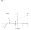
- FIG. 2 shows in a schematic form the unfolded scanning beam path including some relevant geometric variables in the first variant of the position measuring device according to the invention.
- LQ VIRT indicates the position of the virtual light source plane
- RE the reflector element
- LQ denotes the real light source
- the quantity T1 indicates the graduation period of the sampled material measure
- T2 the graduation period of the periodic fringe pattern resulting in the detection level D.
- the position of the virtual light source in the scanning beam along the measurement direction x indicated with the coordinate x_LQ REAL the position of the real light source, such as in the FIGS. 1 a and 1b explained.
- the quantity u represents the distance between the virtual light source plane LQ VIRT and the scale M
- the quantity v denotes the distance between the scale M and the detection plane D.
- This is possible as from FIG. 2 evident by the use of a reflector element RE at the specified position;
- the size u in the defined conditions can be specifically influenced in a defined manner. Since it is no longer necessary to arrange the actual light source LQ in the detection plane D, a number of degrees of freedom with regard to the arrangement of the light source LQ in the scanning unit result.
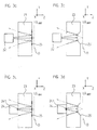
- FIGS. 3a-3d show in highly schematized form different variants for the arrangement and / or configuration of the reflector element and the light source in the scanning unit.
- FIG. 3a a variant is shown in which, with respect to the light source 24 'on the second side of the carrier substrate 23, the reflector element 25 is integrally formed in this side.
- the reflector element 25 is in this case formed by a diffractive grating structure in this example.
- a lattice structure may be, for example, multi-stage phase gratings with a blaze structure or else ideal blazed grating structures.
- Dashed in FIG. 3a drawn, is also the position of the virtual light source in the plane LQ VIRT , which coincides with the detector plane D as desired.
- FIG. 3b A second, alternative embodiment of a suitable reflector element is shown in FIG. 3b shown. Only the differences from the previous examples will be explained below; otherwise the same reference numerals as previously used for functionally identical elements.
- FIG. 3b is the reflector element 25 'on the second side of the carrier substrate 23, opposite to the light source 24', now formed as a refractive optical element with the desired optical effect.
- a mirror can be formed, which has a corresponding optical reflection effect on the radiation beam incident thereon.
- the corresponding reflector contour will be formed aspherical at this point.
- the carrier substrate 23 still assumes the positioning and contacting of the light source 24.
- both complex adjustment work during assembly and the need for a separate light source carrier substrate are eliminated.
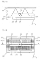
- FIGS. 4a and 4b show analogous to the representation in the FIGS. 1a and 1b Again, a highly schematic sectional view of the scanning beam and a top view of the scanning unit 200. Explained below are only the relevant differences, for example, from the FIGS. 1 a and 1 b.
- a carrier board 210 is provided on the side of the scanning unit 200, on which the detector unit 220 with the two detector arrangements 221, 222 is placed.
- the transparent carrier substrate 230 arranged above it is now of clearly larger area and largely covers the detector arrangements 221, 222 or the detector unit 220. This ensures improved protection of the detector unit 220 from mechanical damage.
- the electrical contacting in particular of the detector arrangements 221, 222, takes place.
- the carrier substrate 230 is also used for electrical contacting thereof.
- a corresponding contacting track runs 241 on the top of the carrier substrate 230 and ends in the edge region thereof in contact pads.
- the electrical contacting of the detector arrangements 221, 222 or the detector unit takes place via further contacting printed conductors 223 on the underside of the carrier substrate 230 between the carrier substrate 230 and the detector unit 220.
- the contacting of the detector arrangements 221, 222 is different to the above example, therefore, no bonding wires used, but planar arranged contacting tracks 241, 223 on the underside of the carrier substrate 230. This allows the use of known flip-chip bonding method in the manufacture of this assembly.
- the basic optical structure is identical to the example above.
- the optical functionality of the reflector element 250 on the second side or underside of the carrier substrate 230 corresponds to that of FIG FIG. 1 a and 1 b.
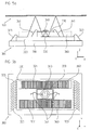
- FIGS. 5a, 5b and FIG. 6 a second variant of the position-measuring device according to the invention will be explained below.
- the location of the light source can be virtually displaced into the detection plane.
- the desired independence, in particular the incremental scanning of the scanning distance is thus guaranteed.
- constellations with certain predetermined geometric boundary conditions in which despite the use of a reflector element, the virtual luminous point of the light source does not come to lie in the detection plane, but lies in front of the detection plane.
- the second variant of the position-measuring device according to the invention offers a solution on the detection side in order to be able to use targeted ensure optical measures in the scanning beam that the virtual luminous point of the light source or the virtual light source comes to rest in the detection plane.
- FIGS. 5a and 5b A suitable for solving this problem position measuring device is in the FIGS. 5a and 5b again shown in a very schematic way.
- the second variant of the position measuring device according to the invention is based on the illustrated variant in the FIGS. 1 a and 1 b. In the following, only the measures provided in addition to the first variant will be explained.
- optical transmission elements 360 are designed as plane-parallel glass plates with specific optical properties (thickness d, refractive index n) and in the example completely cover the respective detector arrangements 321, 322.
- the further structure of the scanning unit 300 and the reflection measuring graduation 100 corresponds to that of the FIGS. 1 a and 1 b.
- optical transmission elements 360 are arranged to ensure the desired position of the virtual light source in the detection plane.
- these additional measures can in principle be used without the first-mentioned measures in connection with the reflector element. That is, it may be sufficient for certain geometrical boundary conditions, to take only these measures and to dispense with the arrangement of the reflector element according to the first variant. In this case, then would be only suitable to arrange optical transmission elements in the scanning beam, such as in the form of plane-parallel glass plates above the detector arrays.
- FIGS. 6a and 6b For a more detailed explanation of the second variant and the addition of the transmission elements resulting optical effects on the scanning beam is on the FIGS. 6a and 6b directed.
- FIG. 6a again shows in schematic form the unfolded scanning beam path including various relevant geometric parameters;
- FIG. 6b represents a section FIG. 6a represents.
- the radiation beam emitted by the real (point) light source at the location x_LQ REAL in the plane LQ REAL is first appropriately widened via an expansion optics AO.
- the expansion optics AO is usually designed as an optical transmission element, for example as a lens, and has a thickness D and a refractive index n1.
- the illustrated light beam of the emitted beam undergoes the desired optical effect in the form of refraction at the boundary surfaces of the expansion optics AO during the entry and exit, and leaves the expansion optics AO (beam-expanded) as in FIG FIG. 6a represented at the angle ⁇ .
- the location of the virtual x_LQ VIRT luminous spot is obtained as shown by the dashed, rearward extension of the transmitted output light beam is illustrated as in the expansion optics AO lying in the plane LQ VIRT; this level is offset by the amount x1 offset from the entrance interface in the interior of the expansion optics AO.
- the distance u in turn represents the distance between the material measure plane M and the virtual light source plane LQ VIRT . From the side of the material measure, the virtual luminance point therefore appears at the angle ⁇ .
- the second variant of the position measuring device to bring the detection level virtually in the desired position, ie in the virtual detection plane D VIRT ;
- the placement of the detector arrangement is of course carried out in a suitable real detection plane D REAL .
- the virtual detection plane D VIRT is as in FIG. 6a illustrated by the distance x2 away from the real detection plane D REAL .
- an optical transmission element OT with the thickness d and the refractive index n2 is now arranged in the scanning beam path so that a defined optical effect on the scanning beam path results over it.
- FIG. 6b is the optical effect of the transmission element OT illustrated in an enlarged view, in particular the resulting deflection effects for the transmitted beam.
- the optical effect of the transmission element OT as well as considerations for the embodiment desselbigen based on FIGS. 6a and 6b explained in detail.
- the aim here is that the virtual detection plane D VIRT is brought into the also virtual light source plane L VIRT .
- the virtual light source plane L VIRT is located at the distance x1 from the surface of the expansion optics . This results in the requirement that x2> x1 must be selected if a real placement of the detector arrangement is to take place outside the widening optics AO or the transmission element OT.
- the real beam path to a detector arrangement outside the transmission element OT and the (dashed) beam path to a virtual detector array at the position x_D VIRT iw differ by taking into account the resulting at the entrance interface refraction in the case of the real beam path ; in the case of the virtual beam path, this is not considered as shown.
- the position of the virtual detection plane can thus be set as desired in order to ensure the desired advantages in the scanning.
- appropriately designed optical transmission elements are formed with suitable thicknesses d as plane-parallel glass plates, which are arranged above the (real) detector arrays.
- the optical transmission elements can also be provided with further optically active structures, such as with grating structures or lens structures, in order to correct any resulting aberrations. Furthermore, it can be ensured via such elements that light is incident only perpendicular to the detector arrangement and thus undesirable crosstalk between adjacent detector elements due to oblique incidence of light can be avoided.
- optically effective portions can be formed to influence the scanning beam when needed.
- These may be further diffractive structures or gratings or else refractive structures or reflectors.
- these are all arranged or formed only on one side, such as the underside, of the carrier substrate.
- the carrier substrate is electrically connected to the detector unit via a flip-chip contacting
- a suitable filling material or a so-called underfiller can be arranged in the intermediate space, which protects the optically active structures formed on the underside in the carrier substrate etc.
Landscapes
- Physics & Mathematics (AREA)
- General Physics & Mathematics (AREA)
- Optical Transform (AREA)
- Length Measuring Devices By Optical Means (AREA)
Applications Claiming Priority (1)
| Application Number | Priority Date | Filing Date | Title |
|---|---|---|---|
| DE102006021017A DE102006021017A1 (de) | 2006-05-05 | 2006-05-05 | Positionsmesseinrichtung |
Publications (2)
| Publication Number | Publication Date |
|---|---|
| EP1852684A1 EP1852684A1 (de) | 2007-11-07 |
| EP1852684B1 true EP1852684B1 (de) | 2012-08-15 |
Family
ID=38288545
Family Applications (1)
| Application Number | Title | Priority Date | Filing Date |
|---|---|---|---|
| EP07007787A Not-in-force EP1852684B1 (de) | 2006-05-05 | 2007-04-17 | Positionsmesseinrichtung |
Country Status (6)
| Country | Link |
|---|---|
| US (1) | US7473886B2 (enExample) |
| EP (1) | EP1852684B1 (enExample) |
| JP (1) | JP4982242B2 (enExample) |
| CN (1) | CN101067560B (enExample) |
| DE (1) | DE102006021017A1 (enExample) |
| ES (1) | ES2389734T3 (enExample) |
Families Citing this family (16)
| Publication number | Priority date | Publication date | Assignee | Title |
|---|---|---|---|---|
| DE102006021017A1 (de) * | 2006-05-05 | 2007-11-08 | Dr. Johannes Heidenhain Gmbh | Positionsmesseinrichtung |
| DE102007028943A1 (de) | 2007-06-22 | 2008-12-24 | Dr. Johannes Heidenhain Gmbh | Abtasteinheit für eine optische Positionsmesseinrichtung |
| DE102008025870A1 (de) | 2008-05-31 | 2009-12-03 | Dr. Johannes Heidenhain Gmbh | Optische Positionsmesseinrichtung |
| DE102009001262A1 (de) | 2009-03-02 | 2010-09-09 | Dr. Johannes Heidenhain Gmbh | Positionsmesseinrichtung |
| DE102010028725B4 (de) | 2010-05-07 | 2023-05-25 | Dr. Johannes Heidenhain Gmbh | Positionsmesseinrichtung |
| EP2606314A2 (de) * | 2010-08-19 | 2013-06-26 | ELESTA relays GmbH | Positionsmessvorrichtung und verfahren zur ermittlung einer absoluten position |
| WO2012050130A1 (ja) | 2010-10-12 | 2012-04-19 | 株式会社ニコン | エンコーダ、駆動装置及びロボット装置 |
| US9383229B2 (en) | 2010-10-31 | 2016-07-05 | Avego Technologies General Ip (Singapore) Pte. Ltd. | Optical reflective encoder with multi-faceted flat-faced lens |
| DE102011007459B4 (de) | 2011-04-15 | 2023-05-11 | Dr. Johannes Heidenhain Gmbh | Optische Längenmesseinrichtung |
| DE102011082570A1 (de) * | 2011-09-13 | 2013-03-14 | Dr. Johannes Heidenhain Gmbh | Rotatorische Positionsmesseinrichtung |
| CN102325233A (zh) * | 2011-10-10 | 2012-01-18 | 朱杰 | 带有多扫描阵列的接触式图像传感器 |
| EP3009806B1 (de) * | 2014-10-14 | 2016-12-14 | Dr. Johannes Heidenhain GmbH | Positionsmesseinrichtung mit Vorrichtung zur Kompensation von Fehlern durch thermische Dilatation eines Massstabes |
| DE102015219810A1 (de) * | 2015-10-13 | 2017-04-13 | Dr. Johannes Heidenhain Gmbh | X-Y-Tisch mit einer Positionsmesseinrichtung |
| TW201741618A (zh) * | 2016-05-23 | 2017-12-01 | 國立交通大學 | 光學感測裝置 |
| GB201916641D0 (en) | 2019-11-15 | 2020-01-01 | Renishaw Plc | Position measurement device |
| GB201916662D0 (en) * | 2019-11-15 | 2020-01-01 | Renishaw Plc | Encoder apparatus |
Family Cites Families (9)
| Publication number | Priority date | Publication date | Assignee | Title |
|---|---|---|---|---|
| US5317149A (en) * | 1992-11-12 | 1994-05-31 | Hewlett-Packard Company | Optical encoder with encapsulated electrooptics |
| US6424407B1 (en) * | 1998-03-09 | 2002-07-23 | Otm Technologies Ltd. | Optical translation measurement |
| WO1999046603A1 (en) * | 1998-03-09 | 1999-09-16 | Otm Technologies, Ltd. | Optical translation measurement |
| JP4812189B2 (ja) * | 2001-06-15 | 2011-11-09 | オリンパス株式会社 | 光学式検出装置 |
| US6723980B2 (en) * | 2001-07-16 | 2004-04-20 | Wai-Hon Lee | Position sensor with grating to detect moving object with periodic pattern |
| JP4658452B2 (ja) * | 2003-02-07 | 2011-03-23 | オリンパス株式会社 | 光学式エンコーダ |
| JP4021382B2 (ja) * | 2003-07-28 | 2007-12-12 | オリンパス株式会社 | 光学式エンコーダ及びその製造方法並びに光学レンズモジュール |
| US20070120048A1 (en) * | 2005-11-25 | 2007-05-31 | Lum Chee F | Reflective encoder module |
| DE102006021017A1 (de) * | 2006-05-05 | 2007-11-08 | Dr. Johannes Heidenhain Gmbh | Positionsmesseinrichtung |
-
2006
- 2006-05-05 DE DE102006021017A patent/DE102006021017A1/de not_active Withdrawn
-
2007
- 2007-04-17 EP EP07007787A patent/EP1852684B1/de not_active Not-in-force
- 2007-04-17 ES ES07007787T patent/ES2389734T3/es active Active
- 2007-04-30 CN CN2007101023284A patent/CN101067560B/zh not_active Expired - Fee Related
- 2007-05-02 JP JP2007121437A patent/JP4982242B2/ja not_active Expired - Fee Related
- 2007-05-07 US US11/801,057 patent/US7473886B2/en not_active Expired - Fee Related
Also Published As
| Publication number | Publication date |
|---|---|
| JP4982242B2 (ja) | 2012-07-25 |
| CN101067560B (zh) | 2011-08-03 |
| US20070262250A1 (en) | 2007-11-15 |
| US7473886B2 (en) | 2009-01-06 |
| EP1852684A1 (de) | 2007-11-07 |
| CN101067560A (zh) | 2007-11-07 |
| DE102006021017A1 (de) | 2007-11-08 |
| ES2389734T3 (es) | 2012-10-31 |
| JP2007298522A (ja) | 2007-11-15 |
Similar Documents
| Publication | Publication Date | Title |
|---|---|---|
| EP1852684B1 (de) | Positionsmesseinrichtung | |
| EP1319170B1 (de) | Positionsmesseinrichtung | |
| EP1739395B1 (de) | Positionsmesseinrichtung | |
| EP1923673B1 (de) | Positionsmesseinrichtung | |
| DE69320716T3 (de) | Gerät zur Detektion von Verschiebungsinformation | |
| DE102008007319A1 (de) | Optische Positionsmesseinrichtung | |
| EP2404143B1 (de) | Positionsmesseinrichtung | |
| DE10217726A1 (de) | Optische Positionsmesseinrichtung | |
| DE10058239B4 (de) | Positionsmeßeinrichtung | |
| EP3136057B1 (de) | Optische positionsmesseinrichtung | |
| EP1028309B1 (de) | Optische Positionsmesseinrichtung | |
| DE102016015225B4 (de) | Codiereinrichtung | |
| EP2570780B1 (de) | Rotatorische Positionsmesseinrichtung | |
| DE19855307B4 (de) | Abtasteinheit für eine optische Positionsmeßeinrichtung | |
| EP1377799B1 (de) | Optische positionsmesseinrichtung | |
| EP3220106B1 (de) | Optischer abstandssensor und positionsmesseinrichtung mit einem derartigen abstandssensor | |
| DE102007028943A1 (de) | Abtasteinheit für eine optische Positionsmesseinrichtung | |
| WO2003021237A2 (de) | Verfahren und vorrichtung zum messen von translationsbewegungen zwischen einer oberfläche und einer messvorrichtung | |
| DE102010028725B4 (de) | Positionsmesseinrichtung | |
| DE102018205857B4 (de) | Vorrichtung zur interferentiellen Abstandsmessung | |
| DE3928064A1 (de) | Lichtelektrische positionsmesseinrichtung | |
| EP0967467B1 (de) | Optoelektronische Sensoranordnung | |
| DE19957777A1 (de) | Optische Positionsmeßeinrichtung | |
| DE19538228A1 (de) | Positionserfassungseinrichtung | |
| DE29825156U1 (de) | Abtasteinheit für eine optische Positionsmesseinrichtung |
Legal Events
| Date | Code | Title | Description |
|---|---|---|---|
| PUAI | Public reference made under article 153(3) epc to a published international application that has entered the european phase |
Free format text: ORIGINAL CODE: 0009012 |
|
| AK | Designated contracting states |
Kind code of ref document: A1 Designated state(s): AT BE BG CH CY CZ DE DK EE ES FI FR GB GR HU IE IS IT LI LT LU LV MC MT NL PL PT RO SE SI SK TR |
|
| AX | Request for extension of the european patent |
Extension state: AL BA HR MK YU |
|
| 17P | Request for examination filed |
Effective date: 20080507 |
|
| AKX | Designation fees paid |
Designated state(s): AT BE BG CH CY CZ DE DK EE ES FI FR GB GR HU IE IS IT LI LT LU LV MC MT NL PL PT RO SE SI SK TR |
|
| 17Q | First examination report despatched |
Effective date: 20101126 |
|
| GRAP | Despatch of communication of intention to grant a patent |
Free format text: ORIGINAL CODE: EPIDOSNIGR1 |
|
| GRAS | Grant fee paid |
Free format text: ORIGINAL CODE: EPIDOSNIGR3 |
|
| GRAA | (expected) grant |
Free format text: ORIGINAL CODE: 0009210 |
|
| AK | Designated contracting states |
Kind code of ref document: B1 Designated state(s): AT BE BG CH CY CZ DE DK EE ES FI FR GB GR HU IE IS IT LI LT LU LV MC MT NL PL PT RO SE SI SK TR |
|
| REG | Reference to a national code |
Ref country code: CH Ref legal event code: EP Ref country code: GB Ref legal event code: FG4D Free format text: NOT ENGLISH Ref country code: AT Ref legal event code: REF Ref document number: 571068 Country of ref document: AT Kind code of ref document: T Effective date: 20120815 |
|
| REG | Reference to a national code |
Ref country code: IE Ref legal event code: FG4D Free format text: LANGUAGE OF EP DOCUMENT: GERMAN |
|
| REG | Reference to a national code |
Ref country code: DE Ref legal event code: R096 Ref document number: 502007010369 Country of ref document: DE Effective date: 20121011 |
|
| REG | Reference to a national code |
Ref country code: ES Ref legal event code: FG2A Ref document number: 2389734 Country of ref document: ES Kind code of ref document: T3 Effective date: 20121031 |
|
| REG | Reference to a national code |
Ref country code: NL Ref legal event code: VDEP Effective date: 20120815 |
|
| PG25 | Lapsed in a contracting state [announced via postgrant information from national office to epo] |
Ref country code: CY Free format text: LAPSE BECAUSE OF FAILURE TO SUBMIT A TRANSLATION OF THE DESCRIPTION OR TO PAY THE FEE WITHIN THE PRESCRIBED TIME-LIMIT Effective date: 20120815 Ref country code: IS Free format text: LAPSE BECAUSE OF FAILURE TO SUBMIT A TRANSLATION OF THE DESCRIPTION OR TO PAY THE FEE WITHIN THE PRESCRIBED TIME-LIMIT Effective date: 20121215 Ref country code: LT Free format text: LAPSE BECAUSE OF FAILURE TO SUBMIT A TRANSLATION OF THE DESCRIPTION OR TO PAY THE FEE WITHIN THE PRESCRIBED TIME-LIMIT Effective date: 20120815 Ref country code: FI Free format text: LAPSE BECAUSE OF FAILURE TO SUBMIT A TRANSLATION OF THE DESCRIPTION OR TO PAY THE FEE WITHIN THE PRESCRIBED TIME-LIMIT Effective date: 20120815 |
|
| PG25 | Lapsed in a contracting state [announced via postgrant information from national office to epo] |
Ref country code: LV Free format text: LAPSE BECAUSE OF FAILURE TO SUBMIT A TRANSLATION OF THE DESCRIPTION OR TO PAY THE FEE WITHIN THE PRESCRIBED TIME-LIMIT Effective date: 20120815 Ref country code: SE Free format text: LAPSE BECAUSE OF FAILURE TO SUBMIT A TRANSLATION OF THE DESCRIPTION OR TO PAY THE FEE WITHIN THE PRESCRIBED TIME-LIMIT Effective date: 20120815 Ref country code: PT Free format text: LAPSE BECAUSE OF FAILURE TO SUBMIT A TRANSLATION OF THE DESCRIPTION OR TO PAY THE FEE WITHIN THE PRESCRIBED TIME-LIMIT Effective date: 20121217 Ref country code: PL Free format text: LAPSE BECAUSE OF FAILURE TO SUBMIT A TRANSLATION OF THE DESCRIPTION OR TO PAY THE FEE WITHIN THE PRESCRIBED TIME-LIMIT Effective date: 20120815 Ref country code: GR Free format text: LAPSE BECAUSE OF FAILURE TO SUBMIT A TRANSLATION OF THE DESCRIPTION OR TO PAY THE FEE WITHIN THE PRESCRIBED TIME-LIMIT Effective date: 20121116 Ref country code: SI Free format text: LAPSE BECAUSE OF FAILURE TO SUBMIT A TRANSLATION OF THE DESCRIPTION OR TO PAY THE FEE WITHIN THE PRESCRIBED TIME-LIMIT Effective date: 20120815 |
|
| PG25 | Lapsed in a contracting state [announced via postgrant information from national office to epo] |
Ref country code: NL Free format text: LAPSE BECAUSE OF FAILURE TO SUBMIT A TRANSLATION OF THE DESCRIPTION OR TO PAY THE FEE WITHIN THE PRESCRIBED TIME-LIMIT Effective date: 20120815 |
|
| PG25 | Lapsed in a contracting state [announced via postgrant information from national office to epo] |
Ref country code: CZ Free format text: LAPSE BECAUSE OF FAILURE TO SUBMIT A TRANSLATION OF THE DESCRIPTION OR TO PAY THE FEE WITHIN THE PRESCRIBED TIME-LIMIT Effective date: 20120815 Ref country code: EE Free format text: LAPSE BECAUSE OF FAILURE TO SUBMIT A TRANSLATION OF THE DESCRIPTION OR TO PAY THE FEE WITHIN THE PRESCRIBED TIME-LIMIT Effective date: 20120815 Ref country code: RO Free format text: LAPSE BECAUSE OF FAILURE TO SUBMIT A TRANSLATION OF THE DESCRIPTION OR TO PAY THE FEE WITHIN THE PRESCRIBED TIME-LIMIT Effective date: 20120815 Ref country code: DK Free format text: LAPSE BECAUSE OF FAILURE TO SUBMIT A TRANSLATION OF THE DESCRIPTION OR TO PAY THE FEE WITHIN THE PRESCRIBED TIME-LIMIT Effective date: 20120815 |
|
| PG25 | Lapsed in a contracting state [announced via postgrant information from national office to epo] |
Ref country code: IT Free format text: LAPSE BECAUSE OF FAILURE TO SUBMIT A TRANSLATION OF THE DESCRIPTION OR TO PAY THE FEE WITHIN THE PRESCRIBED TIME-LIMIT Effective date: 20120815 Ref country code: SK Free format text: LAPSE BECAUSE OF FAILURE TO SUBMIT A TRANSLATION OF THE DESCRIPTION OR TO PAY THE FEE WITHIN THE PRESCRIBED TIME-LIMIT Effective date: 20120815 |
|
| PLBE | No opposition filed within time limit |
Free format text: ORIGINAL CODE: 0009261 |
|
| STAA | Information on the status of an ep patent application or granted ep patent |
Free format text: STATUS: NO OPPOSITION FILED WITHIN TIME LIMIT |
|
| 26N | No opposition filed |
Effective date: 20130516 |
|
| PG25 | Lapsed in a contracting state [announced via postgrant information from national office to epo] |
Ref country code: BG Free format text: LAPSE BECAUSE OF FAILURE TO SUBMIT A TRANSLATION OF THE DESCRIPTION OR TO PAY THE FEE WITHIN THE PRESCRIBED TIME-LIMIT Effective date: 20121115 |
|
| REG | Reference to a national code |
Ref country code: DE Ref legal event code: R097 Ref document number: 502007010369 Country of ref document: DE Effective date: 20130516 |
|
| BERE | Be: lapsed |
Owner name: DR. JOHANNES HEIDENHAIN G.M.B.H. Effective date: 20130430 |
|
| PG25 | Lapsed in a contracting state [announced via postgrant information from national office to epo] |
Ref country code: MC Free format text: LAPSE BECAUSE OF FAILURE TO SUBMIT A TRANSLATION OF THE DESCRIPTION OR TO PAY THE FEE WITHIN THE PRESCRIBED TIME-LIMIT Effective date: 20120815 |
|
| REG | Reference to a national code |
Ref country code: CH Ref legal event code: PL |
|
| REG | Reference to a national code |
Ref country code: IE Ref legal event code: MM4A |
|
| PG25 | Lapsed in a contracting state [announced via postgrant information from national office to epo] |
Ref country code: LI Free format text: LAPSE BECAUSE OF NON-PAYMENT OF DUE FEES Effective date: 20130430 Ref country code: BE Free format text: LAPSE BECAUSE OF NON-PAYMENT OF DUE FEES Effective date: 20130430 Ref country code: CH Free format text: LAPSE BECAUSE OF NON-PAYMENT OF DUE FEES Effective date: 20130430 |
|
| REG | Reference to a national code |
Ref country code: FR Ref legal event code: ST Effective date: 20131231 |
|
| PG25 | Lapsed in a contracting state [announced via postgrant information from national office to epo] |
Ref country code: FR Free format text: LAPSE BECAUSE OF NON-PAYMENT OF DUE FEES Effective date: 20130430 |
|
| PG25 | Lapsed in a contracting state [announced via postgrant information from national office to epo] |
Ref country code: IE Free format text: LAPSE BECAUSE OF NON-PAYMENT OF DUE FEES Effective date: 20130417 |
|
| REG | Reference to a national code |
Ref country code: AT Ref legal event code: MM01 Ref document number: 571068 Country of ref document: AT Kind code of ref document: T Effective date: 20130417 |
|
| PG25 | Lapsed in a contracting state [announced via postgrant information from national office to epo] |
Ref country code: AT Free format text: LAPSE BECAUSE OF NON-PAYMENT OF DUE FEES Effective date: 20130417 |
|
| PG25 | Lapsed in a contracting state [announced via postgrant information from national office to epo] |
Ref country code: MT Free format text: LAPSE BECAUSE OF FAILURE TO SUBMIT A TRANSLATION OF THE DESCRIPTION OR TO PAY THE FEE WITHIN THE PRESCRIBED TIME-LIMIT Effective date: 20120815 |
|
| PG25 | Lapsed in a contracting state [announced via postgrant information from national office to epo] |
Ref country code: TR Free format text: LAPSE BECAUSE OF FAILURE TO SUBMIT A TRANSLATION OF THE DESCRIPTION OR TO PAY THE FEE WITHIN THE PRESCRIBED TIME-LIMIT Effective date: 20120815 |
|
| PG25 | Lapsed in a contracting state [announced via postgrant information from national office to epo] |
Ref country code: HU Free format text: LAPSE BECAUSE OF FAILURE TO SUBMIT A TRANSLATION OF THE DESCRIPTION OR TO PAY THE FEE WITHIN THE PRESCRIBED TIME-LIMIT; INVALID AB INITIO Effective date: 20070417 Ref country code: LU Free format text: LAPSE BECAUSE OF NON-PAYMENT OF DUE FEES Effective date: 20130417 |
|
| PGFP | Annual fee paid to national office [announced via postgrant information from national office to epo] |
Ref country code: GB Payment date: 20210421 Year of fee payment: 15 Ref country code: ES Payment date: 20210621 Year of fee payment: 15 |
|
| PGFP | Annual fee paid to national office [announced via postgrant information from national office to epo] |
Ref country code: DE Payment date: 20220420 Year of fee payment: 16 |
|
| GBPC | Gb: european patent ceased through non-payment of renewal fee |
Effective date: 20220417 |
|
| PG25 | Lapsed in a contracting state [announced via postgrant information from national office to epo] |
Ref country code: GB Free format text: LAPSE BECAUSE OF NON-PAYMENT OF DUE FEES Effective date: 20220417 |
|
| REG | Reference to a national code |
Ref country code: ES Ref legal event code: FD2A Effective date: 20230526 |
|
| PG25 | Lapsed in a contracting state [announced via postgrant information from national office to epo] |
Ref country code: ES Free format text: LAPSE BECAUSE OF NON-PAYMENT OF DUE FEES Effective date: 20220418 |
|
| REG | Reference to a national code |
Ref country code: DE Ref legal event code: R119 Ref document number: 502007010369 Country of ref document: DE |
|
| PG25 | Lapsed in a contracting state [announced via postgrant information from national office to epo] |
Ref country code: DE Free format text: LAPSE BECAUSE OF NON-PAYMENT OF DUE FEES Effective date: 20231103 |