EP1850296B1 - Artikelabgabemaschine - Google Patents
Artikelabgabemaschine Download PDFInfo
- Publication number
- EP1850296B1 EP1850296B1 EP05701683A EP05701683A EP1850296B1 EP 1850296 B1 EP1850296 B1 EP 1850296B1 EP 05701683 A EP05701683 A EP 05701683A EP 05701683 A EP05701683 A EP 05701683A EP 1850296 B1 EP1850296 B1 EP 1850296B1
- Authority
- EP
- European Patent Office
- Prior art keywords
- container
- coin
- machine according
- door
- actuation shaft
- Prior art date
- Legal status (The legal status is an assumption and is not a legal conclusion. Google has not performed a legal analysis and makes no representation as to the accuracy of the status listed.)
- Expired - Lifetime
Links
- 230000007246 mechanism Effects 0.000 claims abstract description 40
- 230000008878 coupling Effects 0.000 claims description 24
- 238000010168 coupling process Methods 0.000 claims description 24
- 238000005859 coupling reaction Methods 0.000 claims description 24
- NJPPVKZQTLUDBO-UHFFFAOYSA-N novaluron Chemical compound C1=C(Cl)C(OC(F)(F)C(OC(F)(F)F)F)=CC=C1NC(=O)NC(=O)C1=C(F)C=CC=C1F NJPPVKZQTLUDBO-UHFFFAOYSA-N 0.000 claims description 15
- 238000003780 insertion Methods 0.000 claims description 3
- 230000037431 insertion Effects 0.000 claims description 3
- 230000000717 retained effect Effects 0.000 claims description 3
- 230000009471 action Effects 0.000 claims description 2
- 230000000903 blocking effect Effects 0.000 claims description 2
- 238000009434 installation Methods 0.000 claims description 2
- 238000012423 maintenance Methods 0.000 description 6
- 230000008439 repair process Effects 0.000 description 5
- 239000002775 capsule Substances 0.000 description 3
- 238000010276 construction Methods 0.000 description 2
- 230000002349 favourable effect Effects 0.000 description 1
- 230000005484 gravity Effects 0.000 description 1
- 230000003100 immobilizing effect Effects 0.000 description 1
- 238000001746 injection moulding Methods 0.000 description 1
- 230000001788 irregular Effects 0.000 description 1
- 239000000463 material Substances 0.000 description 1
- 238000012986 modification Methods 0.000 description 1
- 230000004048 modification Effects 0.000 description 1
- 238000003756 stirring Methods 0.000 description 1
- 239000012780 transparent material Substances 0.000 description 1
- 238000009966 trimming Methods 0.000 description 1
Images


Classifications
-
- G—PHYSICS
- G07—CHECKING-DEVICES
- G07F—COIN-FREED OR LIKE APPARATUS
- G07F9/00—Details other than those peculiar to special kinds or types of apparatus
- G07F9/06—Coin boxes
-
- G—PHYSICS
- G07—CHECKING-DEVICES
- G07F—COIN-FREED OR LIKE APPARATUS
- G07F11/00—Coin-freed apparatus for dispensing, or the like, discrete articles
- G07F11/02—Coin-freed apparatus for dispensing, or the like, discrete articles from non-movable magazines
- G07F11/44—Coin-freed apparatus for dispensing, or the like, discrete articles from non-movable magazines in which magazines the articles are stored in bulk
-
- G—PHYSICS
- G07—CHECKING-DEVICES
- G07F—COIN-FREED OR LIKE APPARATUS
- G07F5/00—Coin-actuated mechanisms; Interlocks
- G07F5/02—Coin-actuated mechanisms; Interlocks actuated mechanically by coins, e.g. by a single coin
Definitions
- the present invention generally relates to an article-dispensing machine, and more specifically to a spherical article-dispensing machine, such as capsules containing a surprise object, actuated by a shaft controlled by a coin or token selector.
- a type of article-dispensing machines comprising a structure supporting an at least partly transparent container so as to contain articles to be dispensed is well known, which articles are generally spherical articles, for example, capsules containing a surprise object.
- a dispensing mechanism which is actuated by an actuation shaft that is coupled to a drive shaft controlled by a coin or token selector is installed in the base of said container.
- the drive power making the mentioned drive shaft rotate can be provided mechanically, for example by means of an electric motor, or manually by means of a crank available to the user.
- the introduction of one or more coins or tokens in said coin or token selector allows carrying out an actuation cycle of the dispensing mechanism, whereby it dispenses a predetermined number of said articles from the container, generally only one article, through a delivery outlet located in a place of the structure that can be easily accessed by the user.
- Patent ES-A-2186519 describes an article-dispensing machine in which the structure comprises an opening at its front part in which the container is arranged, which container has a transparent part.
- the container is mounted such that it can rotate a certain angle according to a horizontal axis so as to expose an upper opening for refilling articles.
- the dispensing mechanism is mounted in a lower part of the container and rotates together with such container when it is placed in a refilling situation.
- a closure device that is controlled by means of a key is arranged to lock or unlock the rotation of the container.
- a gear ring of the dispensing mechanism is engaged with a gear wheel connected to the drive shaft actuated by a crank of the coin selector.
- a drawback of this dispensing machine is that the coin selector and other inner mechanisms are difficultly accessed through the refilling opening of the container, unless a significant part of the structure, or each of the structures when the configuration is of a multiple machine, is disassembled. Likewise, once the coin selector is accessed, it is necessary to carry out several operations using tools in the event that such selector is wanted to be removed for its repair or maintenance. The same occurs with the container, because if it is wanted to be completely removed for its repair or maintenance, it is not enough to open the closure device with the key, but rather it is necessary to disassemble several parts using tools. On the other hand, the coins or tokens are collected in a box which is accessed through a door provided with an independent closure device. In short, the machine can have an excessive difficulty during the maintenance and repair operations, which can negatively affect the operating cost.
- An objective of the present invention is to provide an article-dispensing machine provided with a single closure device which allows, in a closed position, locking the container, the coin selector and the coin or token collection box in the respective operating positions thereof, and which in an open position allows refilling or removing the container, removing the coin selector and removing the coins or tokens from the collection box or completely removing such collection box, without needing to use tools.
- Claim 1 discloses the present invention. Preferred embodiments are disclosed in claims 2-19.
- the present invention contributes to reach the previous and other objectives by providing an article-dispensing machine, of the type comprising a structure supporting a container for articles to be dispensed and a dispensing mechanism arranged in the base of said container.
- Said dispensing mechanism is actuated by an actuation shaft coupled to a drive shaft of a coin or token selector to dispense a predetermined number of said articles from the container through a delivery outlet in each actuation cycle of said dispensing mechanism, controlled by the introduction of one or more coins or tokens in said coin or token selector.
- the dispensing machine of the present invention is characterized in that said actuation shaft is coupled to said drive shaft of the coin or token selector by means of a coupling mounted such that it can slide but not rotate on said actuation shaft between a coupled position, in which said coupling can transmit a turning torque from the drive shaft to the actuation shaft, and an uncoupled position, in which the coupling is completely removed from the drive shaft.
- Elastic means are arranged on the actuation shaft to push the coupling towards said coupled position.
- the coin selector which is mounted in a sliding manner in a direction transverse to the actuation shaft, can be removed without the aid of tools.
- the coin selector is mounted in a front panel of the structure in which the delivery outlet and an access opening to the coin or token collection box are further arranged.
- a door which is articulated in relation to the structure can adopt a closed position attached on said front panel, and a closure device controlled by a key allows locking the door in said closed position, thus immobilizing the coin selector in its operating position and covering the access to the collection box.
- Several openings in the door allow the access to the coin selector and to the delivery outlet when the door is closed.
- the container is further mounted in a sliding manner with respect to the structure in an opening thereof on the front panel.
- a pair of bolts is mounted in a base frame of the container, which bolts are pushed and maintained in a fastened position by cam profiles existing in the door when the container is in an operating position and the door is closed.
- the bolts can be manually unfastened and the container can be partially removed in order to expose an upper opening thereof through which articles can refilled, or it can be completely removed for its repair or maintenance.
- the removing mechanism is incorporated in the base frame of the container and can be removed together with it. When the container is placed in its operating position, a gear ring of the removing mechanism automatically engages with a pinion of a gear train coupled to the actuation shaft without the use of tools.
- a single closure device installed in a door attached to the front panel of the machine allows, in its closed position, locking the container, the coin selector and the coin or token collection box in the respective operating positions thereof, whereas in its open position it allows refilling or removing the container, removing the coin selector and removing coins or tokens from the collection box or completely removing such box, without the use of tools. This allows considerably speeding up the refilling and maintenance operations, and reducing the cost of the operation.
- the structure of the machine is designed as a module. Therefore, with a structure mounted on a pedestal and covered with an upper finishing, a simple machine is configured with two structures fixed one over the other, and a double machine is configured by installing a pedestal under the lower structure and a finishing on the upper structure, and so on. Other configurations can also be obtained by laterally coupling two or more structures or groups of structures.
- the article-dispensing machine comprises a structure 1 supporting a container 2 adapted to contain articles to be dispensed.
- a dispensing mechanism 3 ( Figure 6 ) is arranged on the base of said container 2, which mechanism is actuated by a actuation shaft 4 coupled to a drive shaft 5 of a coin or token selector 6 ( Figure 4 ) to dispense a predetermined number of said articles from the container 2 through a delivery outlet 7.
- Said dispensing mechanism 3 is generally adapted to dispense a single article in each actuation cycle controlled by means of the introduction of one or more coins or tokens in said coin or token selector 6.
- the dispensing mechanism 3 is adapted to the shape and size of the article, and is generally favorable for providing the articles with a spherical shape.
- the articles are usually spherical capsules containing different surprise objects with irregular shapes.
- the container 2 has a base frame 18 and one or more transparent walls 19, and is adapted to move horizontally in a sliding manner in relation to the structure 1, between a filling position (shown in Figure 1 ), in which a portion of the container 2 projects from the structure 1 providing an upper filling opening, and a working position (shown in Figure 13 ), in which the container 2 is integrated in the structure 1.
- the dispensing mechanism 3 is installed in said base frame 18 and is operatively and automatically connected and disconnected to the actuation shaft 4 when the container is located in its working and filling positions. Furthermore, if necessary, it is possible to completely remove the container 2 from the machine by pulling the container 2 from its filling position.
- the coin selector 6 is a known manually actuated type and comprises a crank or a knob 58 ( Figs. 4 and 5 ) connected to said drive shaft 5, and a mechanism allowing the rotation of said crank or knob 58 only if a predetermined number of suitable coins or tokens has been introduced through one or more inlet slots.
- the coin or token selector 6 and said delivery outlet 7, as well as an access opening 53 to a coin or token collection box 52, are arranged in a front panel 10 of the structure 1, and a door 15 (shown in Figure 1 in a open position) is joined to the structure 1 by means of a hinge 16 and arranged to cover said front panel 10 in a closed position (shown in Figure 13 ).
- the mentioned door 15, which is shown separately in Figure 10 , includes a first opening 56 allowing the access to the crank or knob 58 of the coin or token selector 6 and a second opening 24 allowing the access to said delivery outlet 7 when the door 15 is in the closed position, whereas the door 15 itself prevents the access to the mentioned coin or token collection box 52.
- a closure mechanism 55 which can be actuated by means of a key from the outside allows locking the door 15 in the closed position.
- the structure 1 comprises a rear panel 28, a pair of side panels 29, 30, an upper panel 31 and a lower panel 32, connected to one another forming a parallelepiped hollow body.
- the front panel 10 has a smaller height than said rear and side panels 28, 29, 30 to provide an opening between an upper edge of the front panel 10 and said upper panel 31 through which the container 2 is installed.
- the side panels 29, 30 include trimmings 59 conjugated with transparent portions of the side walls of the container 2.
- Both the panels 10, 28, 29, 30, 31 32 forming the structure 1, and the parts 18, 19 forming the container 2, as well as a pedestal 48 and an upper finishing 50, which will be explained in more detail below, are obtained by the injection molding of a plastic material.
- Horizontal guides 20 are defined in the side panels 29, 30 of the structure 1, along which guides the base frame 18 of the container 2 is adapted to slide and on which the container 2 is supported.
- the front panel 10 of the structure 1 comprises an opening 11 opposite to an end of the actuation shaft 4 and provided for connecting the mentioned actuation shaft 4 to the drive shaft 5 of the coin or token selector 6.
- the panel 10 defines a fixed mount 12 provided for receiving and fitting a part of the coin or token selector 6 (also see Figure 4 ).
- the position of this fixed mount 12 is such that the drive shaft 5, once the coin or token selector 6 is in its operating position, is aligned with the actuation shaft 4.
- a guide device 13 adapted for the sliding insertion of a moving mount 14 provided to be coupled by fitting in another part of the coin or token selector 6, contributing to immobilize the coin or token selector 6 in its operating position.
- the mentioned fixed and moving mounts 12, 14, as well as said guide device 13, are adapted and arranged to allow sliding movements of the coin or token selector 6 in a direction transverse to the actuation shaft 4 when such selector is installed and uninstalled. It is obviously necessary for the actuation shaft 4 to be uncoupled from the drive shaft 5 in order to carry out these movements of the coin or token selector 6.
- the actuation shaft 4 has mounted next to its end a coupling 8 ( Figures 3 , 4 , 5 and 8 ) which can slide in the longitudinal direction of the actuation shaft 4 between a coupled position ( Figure 4 ) and an uncoupled position ( Figure 5 ), but cannot rotate in relation thereto.
- a stop 60 is fixed in the actuation shaft 4, and elastic means 9 are arranged between said stop 60 and the coupling 8, for example in the form of a helical spring wound on the actuation shaft 4, to push the coupling 8 towards said coupled position.
- the coupling 8 has at one end a cavity (not shown) with a non-circular contour, a polygonal contour for example, adapted to receive an end of the drive shaft 5 having a conjugated non-circular cross-sectional profile.
- Figure 4 shows the coin or token selector 6 housed in the lower mount 12 of the front panel 10, with the drive shaft 5 opposite to the opening 11.
- the upper mount 14 is installed in the guide device 13 to hold the upper part of the coin or token selector 6, and the coupling 8 is in its position coupled to the drive shaft 5. In this coupled position, the coupling 8 can transmit a turning torque from the drive shaft 5 to the actuation shaft 4.
- the coupling 8 is in its uncoupled position, in which it is completely removed from the drive shaft 5, therefore the drive shaft 5 is released to allow removing or placing the coin or token selector 6.
- the upper mount 14 has been removed from the guide device 13 to release the upper part of the coin or token selector 6, and the latter has been transversely moved upwards so as to release it from the lower mount 12, for the purpose of completely removing it.
- the coin or token selector 6 would first be placed in the lower mount 12, with the drive shaft 5 aligned with the actuation shaft 4.
- the upper mount 14 would be then located in its place in the guide device 13, and the coupling 8 would be finally released to couple it to the drive shaft 5 by the force of the elastic means 9.
- a flap 61 is formed next to an upper edge of the upper mount 14, which flap is superimposed to an upper edge of the of the front panel 10 when the upper mount is in its operating position.
- the door 15 includes in its upper inner part a locking configuration 17 adapted to be superimposed to said flap 61 of the moving mount 14 in an operating position when the door 15 is in the closed position.
- the mentioned locking configuration 17 of the door 15 thus immobilizes the moving mount 14, which in turn locks the coin or token selector 6 in its operating position, and the closure device 55 can be actuated by means of the corresponding key to lock the door 15 in the closed position.
- Figure 10 separately shows the door 15 from its inner face.
- the door 15 incorporates a shaft for hinge 16, the first and second openings 56, 24, the locking configuration 17, the cam profiles 27 and the closure device 55.
- the door 15 further includes a window 82 opposite to a pocket defined by a part 83 fixed to the inner face of the door 15.
- the mentioned pocket is adapted to receive the insertion of a sheet 84 incorporating information relating to the number and type of coins or tokens which must be introduced in the coin or token selector 6 for example.
- This sheet 84 can be seen through the window 82 and can be replaced easily.
- the sheet 84 can have information printed on either side relating to either of the two possible forms of use, i.e. for one or two coins or tokens, and the sheet 84 can easily show the suitable face for the selected form of use.
- FIGS 11 and 12 show a suitable coin or token selector 6 for the machine of the present invention, which is described in document ES-A-1058036 , of this applicant.
- the coin or token selector 6 shown in Figures 11 and 12 comprises a body 81 housing a mechanism adapted to select two coins or tokens introduced through two different inlets in each operative cycle.
- the mentioned mechanism includes the mentioned drive shaft 5, a knob 58 adapted to be actuated by a user is connected to an outer end of such shaft. In some embodiments, the knob 58 can be substituted with a winch or another crank.
- the mentioned body 81 has a recessed portion in which a first entrance part 75, shown in Figure 11 , or a second entrance part 78, shown in Figure 12 , can be indistinctly incorporated.
- the mentioned first entrance part 75 shown in Figure 11 defines two slots 76, 77 respectively opposite to said two inlets of the mechanism, to allow introducing two coins or tokens.
- the second entrance part 78 shown in Figure 12 defines a single slot 79 opposite to one of the two inlets to allow introducing a single coin or token.
- the second entrance part 78 includes a blocking portion 80 preventing the access to the other of the two inlets, and an inner configuration (not shown) adapted to cancel the action of at least one element of said mechanism in correspondence with the blocked inlet.
- Figure 6 shows the base frame 18 mentioned above, which forms part of the container 2.
- the base frame 18 integrates in a single part a rear wall 62 of the container 2 and a part 63 of several side walls, whereas a transparent part 19 and the rest 64 of the side walls are integrated in another part made of transparent material (shown in Figure 7 ) adapted to be coupled and fixed to the base frame 18 to complete the container 2.
- a flap 65 projecting from rear wall 62 is used to limit the outward movement of the container in the filling position ( Figure 1 ).
- the container 2 can be completely removed from the filling position by pulling outwards the lower part of such container.
- the removal mechanism 3 which is of a known type and comprises a rotor 66 in which there are formed a number of cavities 67 with no bottom, each cavity being provided to partially house an article and several stirring elements.
- the rotor is mounted to rotate with respect to a shaft 69 above a support plane 70 of the base frame 18, in which an exit 23 is formed ( Figure 7 ).
- a pair of bolts 25 are arranged in a lower front part of the base frame 18 (although there could be only one or more than two bolts with an equivalent result).
- Each of these bolts 25 is mounted in a guided manner in a corresponding configuration 26 of the base frame 18 such that they can be moved between a fastened position, in which the bolt 25 is fastened in a corresponding configuration of the structure 1, thus maintaining the container 2 in its working position, and a released position, in which the bolt 25 does not interfere with said configuration of the structure 1, allowing the movement of the container 2.
- the door 15 includes, for each bolt 25, a cam profile 27 ( Figures 1 and 10 ) arranged to push the bolt 25 towards its fastened position when the door 15 is in the closed position.
- the machine comprises a delivery duct 21 fixed to the structure 1, as shown in Figures 3 and 8 .
- the mentioned delivery duct 21 has an inlet 22 located in a position which is under the exit 23 of the dispensing mechanism 3 when the container 2 is in its working position.
- the delivery duct 21 ends in an opening formed in the front panel 10 defining said delivery outlet 7 which, as usual, will include any type of gate.
- a housing 51 for said collection box 52 is fixed in the lower part of the front panel 10 ( Figure 3 ), which housing can be accessed through the opening 53 of the front panel 10 when the door 15 is in the open position.
- a collection duct 54 is arranged to lead the coins or tokens from an exit of the coin or token selector 6 to an inlet of said housing 51.
- the actuation shaft 4 is horizontally installed with the end having the coupling 8 opposite to the opening 11 of the front panel 19 and with the opposite end mounted in the rear panel 28.
- the machine includes a guiding configuration formed in a side panel of said delivery duct 21.
- This guiding configuration comprises an upper half bearing 43, configured to clasp and guide an upper half of the actuation shaft 4, and a lower half bearing 44, configured to clasp and guide a lower half of the actuation shaft 4.
- Both upper and lower half bearings 43, 44 are mutually aligned and axially moved and separated by a distance that is enough to allow the passage of said intermediate portion of the actuation shaft 4 in a radial direction when the longitudinal shaft thereof is in an inclined position different from its horizontal working position.
- the actuation shaft 4 can thus be removed without the use of tools by uncoupling the coupling 8 and releasing the rear end of the actuation shaft 4 in the manner which will be described below.
- assembly configurations 33, 34, 35 are incorporated in an inner face of the rear panel 28 for the installation of a train of gear wheels comprising an input gear wheel 36, which is integrally connected to the rear end of the actuation shaft 4.
- This rear end of the actuation shaft 4 projects beyond said input gear wheel 36 and is simply inserted and guided in its corresponding assembly configuration 33, but it is not retained therein.
- the train of gear wheels comprises an output gear wheel 38, which is coaxially joined to a driving pinion 39, and the assembly of both wheels is mounted such that it can rotate retained in its corresponding assembly configuration 35, for example, by means of an axial screw 72.
- the train of gear wheels is completed with an intermediate gear wheel 37, which is simultaneously engaged with said input and output gear wheels 36, 38.
- This intermediate gear wheel 37 is axially fixed in its corresponding assembly configuration 34 by means of a screw 42, and comprises, in its side furthest from the rear panel 28, a ring-shaped flange 41 extending at one side of its teeth for the purpose of preventing a movement in the axial direction of the teeth of the input and output gear wheels 36, 38. Therefore, when the intermediate gear wheel 37 is fixed in an assembly configuration 34, its ring-shaped flange 41 retains the actuation shaft 4 in position. In order to release the rear end of the actuation shaft 4, it is enough to loosen the screw 42, with a screwdriver for example, and remove the intermediate gear wheel 37.
- the mentioned driving pinion 39 which is coaxially integral with the output gear wheel 38, is configured and arranged to engage with a gear ring 40 formed in the periphery of the rotor 66 of the dispensing mechanism 3 through an opening 57 of the base frame 18 of the container 2 when the container 2 is in its working position.
- the driving pinion 39 and said gear ring 40 are automatically engaged when the container 2 is moved to its working position, and are automatically disengaged when the container 2 starts moving to its filling position.
- a retaining finger 73 is mounted in the base frame 18, which finger is elastically pushed against the periphery of the rotor 66 through said opening 57 so as to interlock in slots 74 existing in the periphery of the rotor 66 in the suitable angular positions.
- the upper panel 31 and the lower panel 32 of the structure 1 comprise respective positioning configurations 45, 46 in the form of mutually conjugated embossments and depressions.
- the aforementioned pedestal 48 has an upper portion provided with positioning configurations 47 in the form of embossments and depressions adapted to fit in the positioning configurations 46 of the lower panel 32.
- the mentioned upper finishing 50 is adapted to be mounted on the upper panel 31.
- the pedestal 48 optionally comprises wheels 49 ( Figure 1 ) fixed to its lower part.
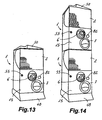
- Figure 13 shows a machine according to the present invention according to a simple configuration, comprising a single structure 1 with a pedestal 48 and an upper finishing 50.
- Figure 14 shows a machine according to the present invention according to a multiple configuration, in which two structures 1 are superimposed and fixed to one another with the mentioned positioning configurations 45 of the upper panel 31 of the lower structure fitted in the positioning configurations 46 of the lower panel 32 of the other superimposed similar structure 1.
- the pedestal is joined to the lower panel of the lower structure 1 and the upper finishing superior is mounted on the upper panel of the upper structure 1.
- the structures 1 can also be laterally attached to form multiple configurations (not shown) formed by rows of two or more simple structures 1, or rows of two or more columns of two or more structures 1 each. In all cases, a pedestal 48 will be mounted under each lower structure 1 and a finishing 50 will be arranged on each upper structure 1.
Landscapes
- Physics & Mathematics (AREA)
- General Physics & Mathematics (AREA)
- Control Of Vending Devices And Auxiliary Devices For Vending Devices (AREA)
- Vending Machines For Individual Products (AREA)
- Feeding Of Articles To Conveyors (AREA)
Claims (19)
- Artikelabgabeautomat, mit einem einen Behälter (2) für abzugebende Artikel stützenden Rahmen (1), einem Abgabemechanismus (3), der am Boden des Behälters (2) angebracht ist und durch eine Abtriebswelle (4) betätigt wird, die mit einer Antriebswelle (5) einer Münzen- oder Markeneinwurföffnung (6) gekoppelt ist, um bei jedem Betätigungstakt des Abgabemechanismus (3) eine vorbestimmte Anzahl von Artikeln aus dem Behälter (2) durch einen Auslauf (7) abzugeben, der durch Einführen einer oder mehrerer Münzen oder Marken in die Münzen- oder Markeneinwurföffnung (6) gesteuert wird, dadurch gekennzeichnet, dass die Abtriebswelle (4) mit der Antriebswelle (5) der Münzen- oder Markeneinwurföffnung (6) über eine Kupplung (8) gekoppelt ist, die so eingebaut ist, dass sie an der Abtriebswelle (4) zwischen einer gekoppelten Stellung, bei der die Kupplung (8) von der Antriebswelle (5) an die Abtriebswelle (4) ein Drehmoment übertragen kann, und einer ungekoppelten Stellung, bei der die Kupplung (8) von der Antriebswelle (5) vollständig gelöst ist, gleitend verschiebbar, jedoch nicht drehbar ist, wobei an der Abtriebswelle (4) Federmittel (9) angebracht sind, um die Kupplung (8) in die gekoppelte Lage zu drücken.
- Automat nach Anspruch 1, dadurch gekennzeichnet, dass eine Vorderwand (10) des Rahmens (1) eine Öffnung (11) gegenüber einem Ende der Abtriebswelle (4), eine feste Halterung (12) neben der Öffnung (11), die zur Aufnahme eines Teils der Münzen- oder Markeneinwurföffnung (6) vorgesehen ist, so dass die Antriebswelle (5) zur Abtriebswelle (4) ausgerichtet ist, sowie eine Führungsvorrichtung (13) zur gleitenden Einführung einer beweglichen Halterung (14) aufweist, die zum Ankoppeln an einen anderen Teil der Münzen- oder Markeneinwurföffnung (6) vorgesehen ist und dadurch zum Festklemmen der Münzen- oder Markeneinwurföffnung (6) in einer Betriebsstellung beiträgt.
- Automat nach Anspruch 2, dadurch gekennzeichnet, dass die feststehende und bewegliche Halterung (12, 14) sowie die Führungsvorrichtung (13) Gleitbewegungen der Münzen- oder Markeneinwurföffnung (6) zwecks Ein- und Ausbau in einer Richtung quer zur Abtriebswelle (4) bei nicht gekoppelter Stellung der Kupplung (8) ermöglichen.
- Automat nach Anspruch 3, dadurch gekennzeichnet, dass er eine Tür (15) umfasst, die mit dem Rahmen (1) über ein Scharnier (16) verbunden und so angeordnet ist, dass sie die Vorderwand (10) in geschlossener Stellung abdeckt, wobei die Tür (15) eine erste Öffnung (56), durch die Zugang zur Münzen- oder Markeneinwurföffnung (6) ermöglicht wird, und eine Verriegelungsstruktur (17) aufweist, mit der die bewegliche Halterung (14) bei geschlossener Stellung der Tür (15) in einer Betriebsstellung festgeklemmt werden kann.
- Automat nach Anspruch 4, dadurch gekennzeichnet, dass der Behälter (2) einen Grundrahmen (18), in dem der Abgabemechanismus (3) eingebaut ist, und Seitenwände aufweist, von denen mindestens eine eine durchsichtige Wand (19) darstellt, wobei der Grundrahmen (18) des Behälters (2) in Führungen (20) des Rahmens (1) zwischen einer Füllstellung, bei der ein Abschnitt des Behälters (2) von des Rahmens (1) hervorsteht und dadurch eine obere Füllöffnung entsteht, und einer Arbeitsstellung, bei der der Behälter (2) in den Rahmen (1) integriert ist und der Abgabemechanismus (3) betriebsfähig mit der Abtriebswelle (4) verbunden ist, horizontal gleitend verschiebbar ist.
- Automat nach Anspruch 5, dadurch gekennzeichnet, dass er einen Auslaufkanal (21) aufweist, der an den Rahmen (1) befestigt ist und einen Einlass (22) aufweist, der sich bei Arbeitsstellung des Behälters (2) unter einem Ausgang (23) des Abgabemechanismus (3) befindet, und in einer in der Vorderwand (10) ausgebildeten Öffnung endet, durch die der Auslauf (7) definiert ist, wobei in der Tür (15) eine zweite Öffnung (24) ausgebildet ist, die bei geschlossener Stellung der Tür (15) den Zugang zum Auslauf (7) ermöglicht.
- Automat nach Anspruch 6, dadurch gekennzeichnet, dass er mindestens einen Bolzen (25) aufweist, der im Grundrahmen (18) des Behälters (2) geführt montiert ist und zwischen einer befestigten Stellung, bei der der Bolzen (25) in einer Ausgestaltung des Rahmens (1) befestigt ist, die den Behälter (2) in dessen Arbeitsstellung hält, und einer gelösten Stellung verschiebbar, bei der der Bolzen (25) die Ausgestaltung des Rahmens (1) nicht behindert und dadurch die Bewegung des Behälters (2) ermöglicht, wobei die Tür (15) ein Kurvenprofil (27) aufweist, das so angeordnet ist, dass der Bolzen (25) bei geschlossener Stellung der Tür (15) in seine befestigte Stellung gedrückt wird.
- Automat nach Anspruch 6 oder 7, dadurch gekennzeichnet, dass die Tür (15) mit einem Schließmechanismus (55) ausgestattet ist, der zum Verschließen der Tür (15) in der geschlossenen Stellung mit einem Schlüssel von außen betätigt werden kann.
- Automat nach Anspruch 4, dadurch gekennzeichnet, dass er ein Gehäuse (51) für einen Sammelkasten (52), der bei geöffneter Stellung der Tür (15) über eine Öffnung (53) an der Vorderwand (10) zugänglich ist, sowie einen Sammelkanal (54) aufweist, der so angeordnet ist, dass Münzen oder Marken von einem Ausgang der Münzen- oder Markeneinwurföffnung (6) zu einem Eingang des Gehäuses (51) geführt werden können.
- Automat nach Anspruch 6, dadurch gekennzeichnet, dass der Rahmen (1) zusätzlich zu der genannten Vorderwand (10), eine Rückwand (28), ein Paar Seitenwände (29, 30), eine obere Wand (31) und eine untere Wand (32) aufweist, wobei die Vorderwand (10) eine geringere Höhe als die Rücken- und Seitenwände (28, 29, 30) aufweist, wodurch zwischen einer oberen Kante der Vorderwand (10) und der oberen Wand (31) eine Öffnung entsteht.
- Automat nach Anspruch 10, dadurch gekennzeichnet, dass in einer Innenfläche der Rückwand (28) Aufbaustrukturen (33, 34, 35) zum Einbau eines Getrieberadzugs mit einem Eingangsgetrieberad (36), das mit dem Ende der Abtriebswelle (4) verbunden ist, und einem Ausgangsgetrieberad (38), das koaxial mit einem Antriebsritzel (39) verbunden ist, das so konfiguriert und angeordnet ist, dass es über eine Öffnung (57) des Grundrahmens (18) des Behälters (2) bei Arbeitsstellung des Behälters (2) mit einem Getriebering (40) des Abgabemechanismus (3) in Eingriff steht.
- Automat nach Anspruch 11, dadurch gekennzeichnet, dass der Getrieberadzug ein Zwischengetrieberad (37) aufweist, das gleichzeitig mit dem Eingangs- und Ausgangsgetrieberad (36, 38) in Eingriff steht, wobei das Zwischengetrieberad (37) an der am weitesten von der Rückwand (28) entfernten Seite einen ringförmigen Flansch (41) aufweist, der sich bis zur Zahnseite erstreckt, damit bei axialer Befestigung des Zwischengetrieberads (37) in der entsprechenden Aufbaustruktur (34) das Eingangs- und Ausgangsgetrieberad (36, 38) mittels einer Schraube (42) axial in Stellung gehalten wird.
- Automat nach Anspruch 12, dadurch gekennzeichnet, dass in einer Seitenwand des Auslaufkanals (21) zur Führung und Stützung eines Zwischenabschnitts der Abtriebswelle (4) eine Führungsstruktur angeordnet ist, wobei die Führungsstruktur ein oberes Halblager (43) und ein unteres Halblager (44) aufweist, die axial verschoben werden und ausreichend getrennt sind, so dass der Zwischenabschnitt der Abtriebswelle (4) bei einer von der Arbeitsstellung der Längswelle verschiedenen Stellung in radialer Richtung verfahren kann.
- Automat nach Anspruch 10, dadurch gekennzeichnet, dass die obere Wand (31) und die untere Wand (32) jeweils zueinander konjugierte Positionierstrukturen (45, 46) aufweisen, wobei die genannten Positionierstrukturen (45) der oberen Wand (31) eines Rahmens (1) so bemessen sind, dass sie in die Positionierstrukturen (46) der unteren Wand (32) eines weiteren überlagerten Rahmens (1) passen.
- Automat nach Anspruch 14, dadurch gekennzeichnet, dass er einen Sockel (48) mit einem oberen Abschnitt mit Positionierstrukturen (47) aufweist, die so bemessen sind, dass sie in die Positionierstrukturen (46) der unteren Wand (32) passen.
- Automat nach Anspruch 15, dadurch gekennzeichnet, dass der Sockel (48) Räder (49) aufweist.
- Automat nach Anspruch 14, dadurch gekennzeichnet, dass er einen oberen Abschluss (50) aufweist, der an der oberen Wand (31) montiert werden kann.
- Automat nach Anspruch 1, 2 oder 3, dadurch gekennzeichnet, dass die Münzen- oder Markeneinwurföffnung (6) einen Mechanismus aufweist, mit dem zwei durch zwei verschiedene Einlässe bei jedem Betriebszyklus eingeführte Münzen oder Marken ausgewählt werden können und der ohne Unterschied einen ersten Eingangsteil (75), durch den zwei Schlitze (76, 77) definiert werden, die jeweils den zwei Einlässen gegenüber liegen, wodurch zwei Münzen oder Marken eingeführt werden können, oder einen zweiten Eingangsteil (78) einschließen kann, durch den ein Schlitz (79) definiert wird, der einem der beiden Einlässe gegenüber liegt, wodurch eine Münze oder Marke eingeführt werden kann, wobei der zweite Eingangsteil (78) einen Sperrabschnitt (80), mit dem der Zugang zum anderen der beiden Einlässe verhindert wird, sowie Mittel zum Abbruch des Bewegungsvorgangs mindestens eines Elements des Mechanismus je nach dem gesperrten Einlass aufweist.
- Automat nach einem der vorhergehenden Ansprüche, dadurch gekennzeichnet, dass die Kupplung (8) durch Bewegung entlang der Abtriebswelle (4) gegen die Kraft der Federmittel (9) lösbar ist; die Münzen- oder Markeneinwurföffnung (6) in einer feststehenden Halterung (12) einer Vorderwand (10) des Rahmens (1) gleitend eingebaut ist und durch Zusammenwirken mit einer beweglichen Halterung (14) in Stellung gehalten wird.
Applications Claiming Priority (1)
| Application Number | Priority Date | Filing Date | Title |
|---|---|---|---|
| PCT/ES2005/000028 WO2006079666A1 (es) | 2005-01-24 | 2005-01-24 | Màquina expendedora de artìculos |
Publications (2)
| Publication Number | Publication Date |
|---|---|
| EP1850296A1 EP1850296A1 (de) | 2007-10-31 |
| EP1850296B1 true EP1850296B1 (de) | 2009-06-17 |
Family
ID=36740058
Family Applications (1)
| Application Number | Title | Priority Date | Filing Date |
|---|---|---|---|
| EP05701683A Expired - Lifetime EP1850296B1 (de) | 2005-01-24 | 2005-01-24 | Artikelabgabemaschine |
Country Status (6)
| Country | Link |
|---|---|
| US (1) | US7789213B2 (de) |
| EP (1) | EP1850296B1 (de) |
| AT (1) | ATE434239T1 (de) |
| CA (1) | CA2595341A1 (de) |
| DE (1) | DE602005015031D1 (de) |
| WO (1) | WO2006079666A1 (de) |
Families Citing this family (5)
| Publication number | Priority date | Publication date | Assignee | Title |
|---|---|---|---|---|
| DE102007007357B4 (de) * | 2007-02-14 | 2018-06-21 | Infineon Technologies Ag | Integrierte Schaltungsanordnung |
| US8459434B2 (en) * | 2009-03-18 | 2013-06-11 | Deltronic Labs, Inc. | Article receiving and detection apparatus and method therefore |
| IT201700043567A1 (it) * | 2017-04-20 | 2018-10-20 | N&W Global Vending S P A | Distributore di contenitori monouso per la preparazione di bevande |
| JP7079800B2 (ja) * | 2020-01-06 | 2022-06-02 | 株式会社バンダイ | 物品供給装置 |
| CZ310506B6 (cs) * | 2023-10-18 | 2025-09-03 | MAREK zemědělská technika s.r.o. | Zařízení na distribuci zboží, zejména brambor nebo zeleniny |
Family Cites Families (12)
| Publication number | Priority date | Publication date | Assignee | Title |
|---|---|---|---|---|
| US3970181A (en) * | 1975-08-11 | 1976-07-20 | National Sanitary Laboratories, Inc. | Two-coin-operated dispensing mechanism |
| US4469242A (en) * | 1982-10-06 | 1984-09-04 | Costa Ralph J | Delivery mechanism for a vending machine |
| JPH08212438A (ja) * | 1995-02-06 | 1996-08-20 | Tomy Ltd | 自動販売機における商品排出装置 |
| US5813510A (en) * | 1996-12-05 | 1998-09-29 | Xcp, Inc. | Currency and coin-activated drop safe |
| US5947328A (en) * | 1997-03-26 | 1999-09-07 | Parkway Machine Corporation | Electronic bulk vending machine system |
| ES1037960Y (es) | 1997-07-28 | 1998-11-01 | Discapa S L | Dispositivo expendedor de articulos. |
| US6113325A (en) * | 1997-09-29 | 2000-09-05 | Craft; Richard D. | Wheelchair restraint system for a transportation vehicle |
| JP3676940B2 (ja) * | 1999-02-25 | 2005-07-27 | 株式会社トミー | コイン選別装置、物品排出装置及びゲーム装置 |
| JP3383631B2 (ja) | 2000-01-27 | 2003-03-04 | 株式会社トミー | 物品排出装置 |
| JP3547390B2 (ja) * | 2000-10-20 | 2004-07-28 | コナミ株式会社 | 自動販売機 |
| JP3836330B2 (ja) * | 2001-05-07 | 2006-10-25 | 株式会社バンダイ | 物品取出装置 |
| US7222711B2 (en) * | 2003-04-16 | 2007-05-29 | Kil Jae Chang | Multiple coin actuation mechanism |
-
2005
- 2005-01-24 US US11/883,045 patent/US7789213B2/en not_active Expired - Fee Related
- 2005-01-24 EP EP05701683A patent/EP1850296B1/de not_active Expired - Lifetime
- 2005-01-24 CA CA002595341A patent/CA2595341A1/en not_active Abandoned
- 2005-01-24 AT AT05701683T patent/ATE434239T1/de not_active IP Right Cessation
- 2005-01-24 DE DE602005015031T patent/DE602005015031D1/de not_active Expired - Fee Related
- 2005-01-24 WO PCT/ES2005/000028 patent/WO2006079666A1/es not_active Ceased
Also Published As
| Publication number | Publication date |
|---|---|
| WO2006079666A1 (es) | 2006-08-03 |
| CA2595341A1 (en) | 2006-08-03 |
| ATE434239T1 (de) | 2009-07-15 |
| DE602005015031D1 (de) | 2009-07-30 |
| US7789213B2 (en) | 2010-09-07 |
| EP1850296A1 (de) | 2007-10-31 |
| US20080156612A1 (en) | 2008-07-03 |
Similar Documents
| Publication | Publication Date | Title |
|---|---|---|
| CN102826131B (zh) | 车辆燃料门的启闭装置 | |
| CN201161372Y (zh) | 用于紧固工具的深度调节机构 | |
| KR101987891B1 (ko) | 스프링 리턴 타입 액추에이터 | |
| AU637296B2 (en) | Motor vehicle door lock controlling device | |
| CN101519931B (zh) | 门锁装置 | |
| US7789213B2 (en) | Article dispensing machine | |
| JP3719363B2 (ja) | 自動販売機の商品払い出し装置 | |
| CN211524444U (zh) | 安装在车门的内面板中的电动儿童锁系统及其车辆 | |
| CN201347661Y (zh) | 保险箱用手柄机构 | |
| CN101092119A (zh) | 可手动锁定的模块盒 | |
| JP7522870B2 (ja) | ロック装置 | |
| DK2921621T3 (en) | Mechanism for opening locking locks using electronic coupling cylinders | |
| GB2209187A (en) | Lockable glove compartment cover for vehicles | |
| JP3455819B2 (ja) | 安全装置 | |
| EP3843055B1 (de) | Artikel-ausgabemechanismus für artikel-verkaufsmaschinen | |
| JP3577731B2 (ja) | キースイッチ | |
| JP5327912B2 (ja) | 遊技機 | |
| US1590700A (en) | Vending machine | |
| KR100763820B1 (ko) | 디지털 도어록용 모티스록 | |
| CN201891291U (zh) | 外拉式保险箱用手柄结构 | |
| CN219672365U (zh) | 具有离合驱动机构的锁具 | |
| JP4491250B2 (ja) | 遊技機 | |
| JP4444176B2 (ja) | 遊技機 | |
| KR20050117908A (ko) | 트레이의 개폐 구조 | |
| KR20140052583A (ko) | 봉투 입출 장치 |
Legal Events
| Date | Code | Title | Description |
|---|---|---|---|
| PUAI | Public reference made under article 153(3) epc to a published international application that has entered the european phase |
Free format text: ORIGINAL CODE: 0009012 |
|
| 17P | Request for examination filed |
Effective date: 20070813 |
|
| AK | Designated contracting states |
Kind code of ref document: A1 Designated state(s): AT BE BG CH CY CZ DE DK EE ES FI FR GB GR HU IE IS IT LI LT LU MC NL PL PT RO SE SI SK TR |
|
| DAX | Request for extension of the european patent (deleted) | ||
| GRAP | Despatch of communication of intention to grant a patent |
Free format text: ORIGINAL CODE: EPIDOSNIGR1 |
|
| GRAS | Grant fee paid |
Free format text: ORIGINAL CODE: EPIDOSNIGR3 |
|
| GRAA | (expected) grant |
Free format text: ORIGINAL CODE: 0009210 |
|
| AK | Designated contracting states |
Kind code of ref document: B1 Designated state(s): AT BE BG CH CY CZ DE DK EE ES FI FR GB GR HU IE IS IT LI LT LU MC NL PL PT RO SE SI SK TR |
|
| REG | Reference to a national code |
Ref country code: GB Ref legal event code: FG4D |
|
| REG | Reference to a national code |
Ref country code: CH Ref legal event code: EP |
|
| REG | Reference to a national code |
Ref country code: IE Ref legal event code: FG4D |
|
| REF | Corresponds to: |
Ref document number: 602005015031 Country of ref document: DE Date of ref document: 20090730 Kind code of ref document: P |
|
| PG25 | Lapsed in a contracting state [announced via postgrant information from national office to epo] |
Ref country code: AT Free format text: LAPSE BECAUSE OF FAILURE TO SUBMIT A TRANSLATION OF THE DESCRIPTION OR TO PAY THE FEE WITHIN THE PRESCRIBED TIME-LIMIT Effective date: 20090617 Ref country code: LT Free format text: LAPSE BECAUSE OF FAILURE TO SUBMIT A TRANSLATION OF THE DESCRIPTION OR TO PAY THE FEE WITHIN THE PRESCRIBED TIME-LIMIT Effective date: 20090617 Ref country code: FI Free format text: LAPSE BECAUSE OF FAILURE TO SUBMIT A TRANSLATION OF THE DESCRIPTION OR TO PAY THE FEE WITHIN THE PRESCRIBED TIME-LIMIT Effective date: 20090617 |
|
| PG25 | Lapsed in a contracting state [announced via postgrant information from national office to epo] |
Ref country code: SE Free format text: LAPSE BECAUSE OF FAILURE TO SUBMIT A TRANSLATION OF THE DESCRIPTION OR TO PAY THE FEE WITHIN THE PRESCRIBED TIME-LIMIT Effective date: 20090917 Ref country code: SI Free format text: LAPSE BECAUSE OF FAILURE TO SUBMIT A TRANSLATION OF THE DESCRIPTION OR TO PAY THE FEE WITHIN THE PRESCRIBED TIME-LIMIT Effective date: 20090617 Ref country code: PL Free format text: LAPSE BECAUSE OF FAILURE TO SUBMIT A TRANSLATION OF THE DESCRIPTION OR TO PAY THE FEE WITHIN THE PRESCRIBED TIME-LIMIT Effective date: 20090617 |
|
| NLV1 | Nl: lapsed or annulled due to failure to fulfill the requirements of art. 29p and 29m of the patents act | ||
| PG25 | Lapsed in a contracting state [announced via postgrant information from national office to epo] |
Ref country code: CZ Free format text: LAPSE BECAUSE OF FAILURE TO SUBMIT A TRANSLATION OF THE DESCRIPTION OR TO PAY THE FEE WITHIN THE PRESCRIBED TIME-LIMIT Effective date: 20090617 Ref country code: ES Free format text: LAPSE BECAUSE OF FAILURE TO SUBMIT A TRANSLATION OF THE DESCRIPTION OR TO PAY THE FEE WITHIN THE PRESCRIBED TIME-LIMIT Effective date: 20090928 Ref country code: RO Free format text: LAPSE BECAUSE OF FAILURE TO SUBMIT A TRANSLATION OF THE DESCRIPTION OR TO PAY THE FEE WITHIN THE PRESCRIBED TIME-LIMIT Effective date: 20090617 Ref country code: EE Free format text: LAPSE BECAUSE OF FAILURE TO SUBMIT A TRANSLATION OF THE DESCRIPTION OR TO PAY THE FEE WITHIN THE PRESCRIBED TIME-LIMIT Effective date: 20090617 Ref country code: IS Free format text: LAPSE BECAUSE OF FAILURE TO SUBMIT A TRANSLATION OF THE DESCRIPTION OR TO PAY THE FEE WITHIN THE PRESCRIBED TIME-LIMIT Effective date: 20091017 |
|
| PG25 | Lapsed in a contracting state [announced via postgrant information from national office to epo] |
Ref country code: NL Free format text: LAPSE BECAUSE OF FAILURE TO SUBMIT A TRANSLATION OF THE DESCRIPTION OR TO PAY THE FEE WITHIN THE PRESCRIBED TIME-LIMIT Effective date: 20090617 Ref country code: BE Free format text: LAPSE BECAUSE OF FAILURE TO SUBMIT A TRANSLATION OF THE DESCRIPTION OR TO PAY THE FEE WITHIN THE PRESCRIBED TIME-LIMIT Effective date: 20090617 Ref country code: SK Free format text: LAPSE BECAUSE OF FAILURE TO SUBMIT A TRANSLATION OF THE DESCRIPTION OR TO PAY THE FEE WITHIN THE PRESCRIBED TIME-LIMIT Effective date: 20090617 |
|
| PG25 | Lapsed in a contracting state [announced via postgrant information from national office to epo] |
Ref country code: PT Free format text: LAPSE BECAUSE OF FAILURE TO SUBMIT A TRANSLATION OF THE DESCRIPTION OR TO PAY THE FEE WITHIN THE PRESCRIBED TIME-LIMIT Effective date: 20091017 Ref country code: BG Free format text: LAPSE BECAUSE OF FAILURE TO SUBMIT A TRANSLATION OF THE DESCRIPTION OR TO PAY THE FEE WITHIN THE PRESCRIBED TIME-LIMIT Effective date: 20090917 |
|
| PLBE | No opposition filed within time limit |
Free format text: ORIGINAL CODE: 0009261 |
|
| STAA | Information on the status of an ep patent application or granted ep patent |
Free format text: STATUS: NO OPPOSITION FILED WITHIN TIME LIMIT |
|
| PG25 | Lapsed in a contracting state [announced via postgrant information from national office to epo] |
Ref country code: DK Free format text: LAPSE BECAUSE OF FAILURE TO SUBMIT A TRANSLATION OF THE DESCRIPTION OR TO PAY THE FEE WITHIN THE PRESCRIBED TIME-LIMIT Effective date: 20090617 |
|
| 26N | No opposition filed |
Effective date: 20100318 |
|
| PG25 | Lapsed in a contracting state [announced via postgrant information from national office to epo] |
Ref country code: MC Free format text: LAPSE BECAUSE OF NON-PAYMENT OF DUE FEES Effective date: 20100131 |
|
| REG | Reference to a national code |
Ref country code: CH Ref legal event code: PL |
|
| GBPC | Gb: european patent ceased through non-payment of renewal fee |
Effective date: 20100124 |
|
| REG | Reference to a national code |
Ref country code: FR Ref legal event code: ST Effective date: 20100930 |
|
| PG25 | Lapsed in a contracting state [announced via postgrant information from national office to epo] |
Ref country code: FR Free format text: LAPSE BECAUSE OF NON-PAYMENT OF DUE FEES Effective date: 20100201 Ref country code: LI Free format text: LAPSE BECAUSE OF NON-PAYMENT OF DUE FEES Effective date: 20100131 Ref country code: CH Free format text: LAPSE BECAUSE OF NON-PAYMENT OF DUE FEES Effective date: 20100131 Ref country code: GR Free format text: LAPSE BECAUSE OF FAILURE TO SUBMIT A TRANSLATION OF THE DESCRIPTION OR TO PAY THE FEE WITHIN THE PRESCRIBED TIME-LIMIT Effective date: 20090918 |
|
| PG25 | Lapsed in a contracting state [announced via postgrant information from national office to epo] |
Ref country code: DE Free format text: LAPSE BECAUSE OF NON-PAYMENT OF DUE FEES Effective date: 20100803 |
|
| PG25 | Lapsed in a contracting state [announced via postgrant information from national office to epo] |
Ref country code: GB Free format text: LAPSE BECAUSE OF NON-PAYMENT OF DUE FEES Effective date: 20100124 |
|
| PG25 | Lapsed in a contracting state [announced via postgrant information from national office to epo] |
Ref country code: IE Free format text: LAPSE BECAUSE OF NON-PAYMENT OF DUE FEES Effective date: 20100124 |
|
| PG25 | Lapsed in a contracting state [announced via postgrant information from national office to epo] |
Ref country code: IT Free format text: LAPSE BECAUSE OF FAILURE TO SUBMIT A TRANSLATION OF THE DESCRIPTION OR TO PAY THE FEE WITHIN THE PRESCRIBED TIME-LIMIT Effective date: 20090617 |
|
| PG25 | Lapsed in a contracting state [announced via postgrant information from national office to epo] |
Ref country code: CY Free format text: LAPSE BECAUSE OF FAILURE TO SUBMIT A TRANSLATION OF THE DESCRIPTION OR TO PAY THE FEE WITHIN THE PRESCRIBED TIME-LIMIT Effective date: 20090617 |
|
| PG25 | Lapsed in a contracting state [announced via postgrant information from national office to epo] |
Ref country code: HU Free format text: LAPSE BECAUSE OF FAILURE TO SUBMIT A TRANSLATION OF THE DESCRIPTION OR TO PAY THE FEE WITHIN THE PRESCRIBED TIME-LIMIT Effective date: 20091218 Ref country code: LU Free format text: LAPSE BECAUSE OF NON-PAYMENT OF DUE FEES Effective date: 20100124 |
|
| PG25 | Lapsed in a contracting state [announced via postgrant information from national office to epo] |
Ref country code: TR Free format text: LAPSE BECAUSE OF FAILURE TO SUBMIT A TRANSLATION OF THE DESCRIPTION OR TO PAY THE FEE WITHIN THE PRESCRIBED TIME-LIMIT Effective date: 20090617 |