EP1849919A1 - Bohrgerät und Verfahren zum Erstellen einer Bohrsäule im Boden - Google Patents
Bohrgerät und Verfahren zum Erstellen einer Bohrsäule im Boden Download PDFInfo
- Publication number
- EP1849919A1 EP1849919A1 EP06008684A EP06008684A EP1849919A1 EP 1849919 A1 EP1849919 A1 EP 1849919A1 EP 06008684 A EP06008684 A EP 06008684A EP 06008684 A EP06008684 A EP 06008684A EP 1849919 A1 EP1849919 A1 EP 1849919A1
- Authority
- EP
- European Patent Office
- Prior art keywords
- drill
- bunker
- pipe
- carriage
- drill pipe
- Prior art date
- Legal status (The legal status is an assumption and is not a legal conclusion. Google has not performed a legal analysis and makes no representation as to the accuracy of the status listed.)
- Granted
Links
Images


Classifications
-
- E—FIXED CONSTRUCTIONS
- E02—HYDRAULIC ENGINEERING; FOUNDATIONS; SOIL SHIFTING
- E02D—FOUNDATIONS; EXCAVATIONS; EMBANKMENTS; UNDERGROUND OR UNDERWATER STRUCTURES
- E02D3/00—Improving or preserving soil or rock, e.g. preserving permafrost soil
- E02D3/02—Improving by compacting
- E02D3/08—Improving by compacting by inserting stones or lost bodies, e.g. compaction piles
-
- E—FIXED CONSTRUCTIONS
- E02—HYDRAULIC ENGINEERING; FOUNDATIONS; SOIL SHIFTING
- E02D—FOUNDATIONS; EXCAVATIONS; EMBANKMENTS; UNDERGROUND OR UNDERWATER STRUCTURES
- E02D7/00—Methods or apparatus for placing sheet pile bulkheads, piles, mouldpipes, or other moulds
- E02D7/02—Placing by driving
- E02D7/06—Power-driven drivers
- E02D7/14—Components for drivers inasmuch as not specially for a specific driver construction
- E02D7/16—Scaffolds or supports for drivers
Definitions
- the invention relates to a drilling rig for creating a drill column in the ground according to the preamble of claim 1, comprising a mast, a carriage slidably mounted on the mast, a drill drive arranged on the carriage for rotationally driving a drill pipe and a pipe bunker connectable to the drill pipe with a storage space for filling material for filling a borehole while pulling the drill pipe.
- the invention further relates to a method for creating a drilling column in the ground according to the preamble of claim 10, wherein a drill pipe is rotatably inserted into the ground by means of a drill drive, which is arranged on a carriage which is displaceable along a mast in the drilling direction, and after reaching a desired depth, the drill pipe is withdrawn and a resulting cavity is filled via the drill pipe with filling material from a pipe bunker arranged on the drill pipe.
- Such a drill is for example from the EP 1 580 325 A1 known.
- a pipe bunker for receiving concrete for filling a borehole is provided on top of a multi-part drill pipe.
- the tubular bunker is in turn held on the upper side on a rotary drive, which can be moved by means of a carriage along a mast.
- a rotary drive which can be moved by means of a carriage along a mast.
- Another drill with a tubular bunker, which is located at the top of a drill pipe is from the US 5,647,690 known.
- the object of the invention is to develop a generic drill and a generic method so that a particularly good usability and versatility is achieved.
- a drilling rig according to the invention is characterized in that the tube bunker is mounted so as to be axially adjustable relative to the carriage on the carriage.
- a first basic idea of the invention can be seen in providing the tubular bunker axially adjustable relative to the carriage, that is to say in particular axially displaceable and fixable at a plurality of axial positions.
- the tubular bunker can be moved, for example, for filling with filler relative to the carriage in a position in which it is particularly accessible.
- the axial stroke when inserting or pulling the drill pipe to be increased.
- a pipe bunker can be understood in particular a product container to which a drill pipe is connected.
- the tubular bunker in the axial direction above, that is arranged at the end facing away from the drill bit of the drill pipe.
- the tube bunker can be arranged as an extension of the drill pipe.
- the axial direction can be understood in particular to be the longitudinal direction of the drill pipe and / or the direction of displacement of the carriage on the mast.
- the tube bunker is mounted axially adjustable with the drill pipe relative to the carriage.
- the drill pipe is axially immovably mounted opposite the pipe bunker.
- a pipe coupling for releasably attaching the drill pipe can be provided on the pipe bunker.
- the drill pipe is suitably designed in several parts.
- a particularly compact drill with a large Bohrhub can be obtained according to the invention in that the tubular bunker is arranged axially above the drill drive and / or the carriage and that the drill pipe is at least partially axially below the drill drive and / or the carriage.
- the composite of tubular bunker and drill pipe passes axially through the drill drive and / or the carriage.
- a filled tube bunker generally has a comparatively high moment of inertia, it may be advantageous to store it rotatably on the carriage. As a result, the required drive power of the drill drive can be kept low and a particularly easy filling of the tubular bunker can be ensured.
- the tubular bunker is rotatably provided on the carriage and in particular rotationally fixed to the drill pipe.
- the tube bunker can rotate during rotation of the connected drill pipe by means of the drill drive.
- a filling material supply means is suitably provided in the tubular bunker, which is non-rotatably arranged with respect to the carriage and / or the mast.
- This feeder can, for example, have a hose connection for a concrete supply line.
- a rotary coupling is provided between the tube bunker and the drill pipe, which decouples a rotation of the drill pipe from the tube bunker.
- the rotary joint is provided axially above the drill drive.
- Such a rotary joint can also be referred to as a flushing head.
- a rotary coupling between the feeder and the tubular bunker may be provided.
- a torque arm for rotationally fixed support of the tubular bunker and / or the feeder for filling material is provided in the tubular bunker on the carriage.
- the tube bunker and / or the feed device are guided axially displaceably on the torque support.
- the torque arm a arranged on the carriage, axially extending boom, on which the tube bunker and / or the feeder is guided axially displaceable, for example via a carriage or via a sleeve guide.
- a drive means for the active axial displacement of the tubular bunker is provided.
- a linear drive can be provided, which is arranged on the one hand on the tubular bunker and on the other hand on the carriage.
- the drive device is arranged on the torque arm.
- an extension tube is provided between the drill pipe and the pipe bunker, which is preferably connected rotationally fixed and axially displaceable with an output shaft of the drill drive.
- the extension tube for example, have a splined shaft.
- the extension tube extends axially through the rotary drive and past the carriage.
- the extension tube may for example be telescoped, in particular as a Kelly bar with longitudinal webs for torque transmission and locking pockets for applying axial forces may be formed.
- a coupling device for coupling the drill pipe can be provided at the lower end of the extension pipe.
- the output shaft of the drill drive is designed as a hollow shaft, on one side of the tube bunker is arranged and on the other side of the drill pipe extends at least in sections.
- a closure device is provided, through which an access for filling material from the tube bunker to the drill pipe can be closed.
- the closure device may, for example, have a flap which is provided at the bottom of the tube bunker, on the extension tube and / or at the top of the drill tube.
- Such a closure device is particularly advantageous when working with a multi-part drill pipe.
- the method according to the invention is characterized in that during the introduction of the drill pipe the pipe bunker, together with the drill pipe, is displaced towards the floor relative to the carriage.
- the Axialhub the drill can be increased and it can be created in a particularly simple manner particularly deep drill columns.
- the pipe bunker, together with the drill pipe moves away from the ground relative to the carriage, that is, is displaced upward.
- the inventive method can be carried out in particular with the drill according to the invention, which can achieve the advantages explained in this context.
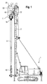
- FIGS. 1 and 2 A first embodiment of a drilling device according to the invention is shown in FIGS. 1 and 2.
- the drill has a chassis 1 on which a mast 2 is pivotally mounted.
- a carriage 22 is provided, which is guided longitudinally displaceably on the mast 2.
- a drill drive 11 is provided, which is displaceable with the carriage 22 along the mast 2 and with which a longitudinally of the mast 2 extending drill pipe 6 with a displacement drill head 80 is set in rotation.
- the drill drive has an upper drive part 12, in which an unillustrated drive motor is provided, as well as an underlying transmission part 13. At this transmission part 13 is designed as a hollow shaft output shaft 19 below.
- an extension pipe 40 is provided in extension of the drill pipe 6.
- This extension tube 40 is rotatably coupled to the drill pipe 6 via a pipe coupling 18 and axially fixed.
- the extension tube 40 passes through the drill drive 11 in the axial direction.
- a pipe bunker 30 is arranged at the upper end of the extension tube 40 at the upper end of the extension tube 40 at the upper end of the extension tube 40 at the upper end of the extension tube 40 is above the auger drive 11 and in extension of the extension tube 40 and the drill pipe 6 .
- the tubular bunker 30 serves to receive filling material, which can be introduced via the extension tube 40 through the drill drive 11 into the drill pipe 6.
- the tube bunker 30, together with the extension tube 40 and the drill pipe 6 arranged thereon, are arranged axially relative to the drill drive 11 and the slide 22, that is to say displaceable in the direction of the arrow A.
- the tubular bunker 30 is in an upper position, in which it is arranged at a comparatively large distance from the drill drive 11. From this position, together with the drill pipe 6 arranged thereon, it can be displaced downwards towards the ground, so that the length of the drill pipe 6 which extends beneath the carriage 22 and the drill drive 11 increases.
- the extension tube 40 which is connected to the drill pipe 6 in a rotationally fixed manner, has splines on the outside, which correspond to internal teeth in the output shaft 19.
- a holding device is provided on the drill drive 11, which holds the extension tube 40, for example non-positively and / or positively.
- a rotary coupling 60 is provided, which decouples a rotation of the drill pipe 6 and of the extension pipe 40 arranged thereon from the pipe bunker 30.
- a torque arm 50 is provided which rotatably coupled to the tubular bunker 30 to the carriage 22.
- the torque arm has an axially extending arm 52, on which the tubular bunker 30 is guided axially displaceably via a side arm.
- the rotary joint 60 is about another side arm, the rotary joint 60, in particular its fixed part, on the arm 52 axially displaceable and rotatably guided.
- the axially extending arm 52 of the torque arm 50 may for example also be made telescopic.
- the tube bunker 30 has an approximately cylindrical storage area 33, which is connected to the extension tube 40 via a conical outlet area 34 arranged therebelow.
- FIG. 3 shows an alternatively formed tube bunker 30 for use in a drilling device according to the invention.
- the tubular bunker of FIG. 3 has an approximately conical cover 36 on the upper side of the cylindrical storage area 33.
- a plurality of filling openings 37 are provided for filling filling material in the interior of the tubular bunker 30.
- the tube bunker of FIG. 3 furthermore has a closure device 71 formed as a flap between the outlet region 34 and extension tube 40, with which a filling material passage between the interior of the tube bunker 30 and the interior of the extension tube 40 and thus the interior of the drill tube 6 can be shut off.
- a closure device 71 formed as a flap between the outlet region 34 and extension tube 40, with which a filling material passage between the interior of the tube bunker 30 and the interior of the extension tube 40 and thus the interior of the drill tube 6 can be shut off.
Landscapes
- Engineering & Computer Science (AREA)
- Life Sciences & Earth Sciences (AREA)
- Structural Engineering (AREA)
- General Engineering & Computer Science (AREA)
- Paleontology (AREA)
- Civil Engineering (AREA)
- Mining & Mineral Resources (AREA)
- General Life Sciences & Earth Sciences (AREA)
- Agronomy & Crop Science (AREA)
- Environmental & Geological Engineering (AREA)
- Soil Sciences (AREA)
- Earth Drilling (AREA)
- Placing Or Removing Of Piles Or Sheet Piles, Or Accessories Thereof (AREA)
Abstract
Description
- Die Erfindung betrifft ein Bohrgerät zum Erstellen einer Bohrsäule im Boden gemäß dem Oberbegriff des Anspruchs 1, mit einem Mast, einem Schlitten, der verschiebbar am Mast gelagert ist, einem an dem Schlitten angeordneten Bohrantrieb zum drehenden Antreiben eines Bohrrohres und einem an dem Bohrrohr anschließbaren Rohrbunker mit einem Speicherraum für Füllmaterial zum Verfüllen eines Bohrlochs beim Ziehen des Bohrrohres.
- Die Erfindung betrifft ferner ein Verfahren zum Erstellen einer Bohrsäule im Boden gemäß dem Oberbegriff des Anspruchs 10, bei dem ein Bohrrohr in den Boden mittels eines Bohrantriebes drehend eingebracht wird, welcher an einem Schlitten angeordnet ist, der entlang eines Mastes in Bohrrichtung verschiebbar ist, und nach Erreichen einer gewünschten Tiefe das Bohrrohr zurückgezogen und ein dabei entstehender Hohlraum über das Bohrrohr mit Füllmaterial aus einem am Bohrrohr angeordneten Rohrbunker verfüllt wird.
- Ein solches Bohrgerät ist beispielsweise aus der
EP 1 580 325 A1 bekannt. Bei diesem bekannten Bohrgerät ist oberseitig an einem mehrteiligen Bohrrohr ein Rohrbunker für die Aufnahme von Beton zum Verfüllen eines Bohrloches vorgesehen. Der Rohrbunker ist seinerseits oberseitig an einem Drehantrieb gehalten, der mittels eines Schlittens längs an einem Mast verfahren werden kann. Beim Abbohren wird der Rohrbunker mittels des Drehantriebes in Drehung versetzt, wobei der Rohrbunker die Drehung an das Bohrrohr überträgt. Zum Verfüllen des entstehenden Bohrloches wird über das Bohrrohr Beton aus dem Rohrbunker in den Boden eingeleitet. - Ein weiteres Bohrgerät mit einem Rohrbunker, der an der Oberseite eines Bohrrohres angeordnet ist, ist aus der
US 5,647,690 bekannt. - Aufgabe der Erfindung ist es, ein gattungsgemäßes Bohrgerät und ein gattungsgemäßes Verfahren so weiterzubilden, dass eine besonders gute Einsetzbarkeit und Vielseitigkeit erzielt wird.
- Die Aufgabe wird erfindungsgemäß durch ein Bohrgerät mit den Merkmalen des Anspruchs 1 sowie durch ein Verfahren mit den Merkmalen des Anspruchs 10 gelöst. Bevorzugte Ausführungsbeispiele sind in den abhängigen Ansprüchen angegeben.
- Ein erfindungsgemäßes Bohrgerät ist dadurch gekennzeichnet, dass der Rohrbunker gegenüber dem Schlitten axial verstellbar am Schlitten gelagert ist.
- Ein erster Grundgedanke der Erfindung kann darin gesehen werden, den Rohrbunker relativ zum Schlitten axial verstellbar, das heißt insbesondere axial verschiebbar und an mehreren Axialpositionen festlegbar, vorzusehen. Somit ist es möglich, den axialen Abstand des Rohrbunkers bezüglich des Schlittens zu variieren, wobei das Bohrrohr zum drehenden Antreiben drehfest mit dem Bohrantrieb gekoppelt bleiben kann. So kann der Rohrbunker beispielsweise zum Befüllen mit Füllmaterial relativ zum Schlitten in eine Position verfahren werden, in der er besonders gut zugänglich ist. Insbesondere kann durch axiales Verstellen des Rohrbunkers der axiale Hub beim Einbringen oder Ziehen des Bohrrohres vergrößert werden.
- Unter einem Rohrbunker kann insbesondere ein Füllgutbehälter verstanden werden, an dem ein Bohrrohr anschließbar ist. Geeigneterweise ist der Rohrbunker in Axialrichtung oben, das heißt an dem der Bohrspitze abgewandten Ende des Bohrrohres angeordnet. Erfindungsgemäß kann der Rohrbunker in Verlängerung des Bohrrohres angeordnet sein. Unter der Axialrichtung kann im Sinne der Erfindung insbesondere die Längsrichtung des Bohrrohres und/oder die Verschieberichtung des Schlittens am Mast verstanden werden.
- Erfindungsgemäß ist es ferner, dass der Rohrbunker mitsamt dem Bohrrohr gegenüber dem Schlitten axial verstellbar gelagert ist. Geeigneterweise ist das Bohrrohr axial unbeweglich gegenüber dem Rohrbunker angebracht. Insbesondere kann am Rohrbunker eine Rohrkupplung zum lösbaren Anbringen des Bohrrohres vorgesehen sein. Das Bohrrohr ist geeigneterweise mehrteilig ausgebildet.
- Ein besonders kompaktes Bohrgerät mit großem Bohrhub kann nach der Erfindung dadurch erhalten werden, dass der Rohrbunker axial oberhalb des Bohrantriebes und/oder des Schlittens angeordnet ist und dass das Bohrrohr zumindest abschnittsweise axial unterhalb des Bohrantriebes und/oder des Schlittens angeordnet ist. Gemäß dieser Ausführungsform läuft der Verbund aus Rohrbunker und Bohrrohr axial durch den Bohrantrieb und/oder den Schlitten hindurch.
- Da ein gefüllter Rohrbunker in der Regel ein vergleichsweise hohes Trägheitsmoment aufweist, kann es vorteilhaft sein, diesen drehfest am Schlitten zu lagern. Hierdurch kann die benötigte Antriebsleistung des Bohrantriebes niedrig gehalten werden und eine besonders leichte Befüllbarkeit des Rohrbunkers gewährleistet werden.
- Für ein konstruktiv besonders einfaches und wirtschaftliches Bohrgerät kann jedoch auch vorgesehen sein, dass der Rohrbunker drehbar am Schlitten und insbesondere drehfest am Bohrrohr vorgesehen ist. In diesem Fall kann sich der Rohrbunker bei Rotation des angeschlossenen Bohrrohres mittels des Bohrantriebes mitdrehen. Um in diesem Fall eine einfache Befüllung des Rohrbunkers zu erlauben, ist geeigneterweise eine Zuführeinrichtung für Füllmaterial in den Rohrbunker vorgesehen, die drehfest bezüglich des Schlittens und/oder des Masts angeordnet ist. Diese Zuführeinrichtung kann beispielsweise einen Schlauchanschluss für eine Betonzuleitung aufweisen.
- Insbesondere wenn der Rohrbunker drehfest am Schlitten vorgesehen ist, ist es vorteilhaft, dass zwischen dem Rohrbunker und dem Bohrrohr eine Drehkupplung vorgesehen ist, die eine Drehung des Bohrrohres vom Rohrbunker entkoppelt. Geeigneterweise ist die Drehkupplung axial oberhalb des Bohrantriebes vorgesehen. Eine solche Drehkupplung kann auch als Spülkopf bezeichnet werden.
- Zusätzlich oder alternativ kann eine Drehkupplung zwischen der Zuführeinrichtung und dem Rohrbunker vorgesehen sein.
- Besonders vorteilhaft ist es nach der Erfindung, dass am Schlitten eine Drehmomentstütze zum drehfesten Abstützen des Rohrbunkers und/oder der Zuführeinrichtung für Füllmaterial in den Rohrbunker vorgesehen ist.
- Ferner ist es vorteilhaft, dass der Rohrbunker und/oder die Zuführeinrichtung an der Drehmomentstütze axial verschiebbar geführt sind. Beispielsweise kann die Drehmomentstütze einen am Schlitten angeordneten, axial verlaufenden Ausleger aufweisen, an dem der Rohrbunker und/oder die Zuführeinrichtung beispielsweise über einen Schlitten oder über eine Hülsenführung axial verschiebbar geführt ist.
- Grundsätzlich ist es möglich, den Rohrbunker beispielsweise durch Schwerkraftwirkung und/oder durch Verschieben des Schlittens bei festgelegtem Rohrbunker axial relativ zum Schlitten zu verschieben. Besonders vorteilhaft ist es jedoch, dass, insbesondere an dem Schlitten, eine Antriebseinrichtung zum aktiven axialen Verschieben des Rohrbunkers vorgesehen ist. Beispielsweise kann ein Linearantrieb vorgesehen sein, der einerseits am Rohrbunker und andererseits am Schlitten angeordnet ist. Bevorzugt ist die Antriebseinrichtung an der Drehmomentstütze angeordnet.
- Erfindungsgemäß ist es ferner, dass zwischen dem Bohrrohr und dem Rohrbunker ein Verlängerungsrohr vorgesehen ist, das vorzugsweise drehfest und axial verschiebbar mit einer Abtriebswelle des Bohrantriebes verbunden ist. Hierzu kann das Verlängerungsrohr beispielsweise eine Keilwellenverzahnung aufweisen. Geeigneterweise verläuft das Verlängerungsrohr axial durch den Drehantrieb hindurch und am Schlitten vorbei. Das Verlängerungsrohr kann beispielsweise teleskopierbar, insbesondere als Kellystange mit Längsstegen zur Drehmomentübertragung und Verriegelungstaschen zum Aufbringen von Axialkräften, ausgebildet sein. Erfindungsgemäß kann am unteren Ende des Verlängerungsrohres eine Kupplungseinrichtung zum Ankoppeln des Bohrrohres vorgesehen sein.
- Ferner ist es vorteilhaft, dass die Abtriebswelle des Bohrantriebs als Hohlwelle ausgebildet ist, an deren einen Seite der Rohrbunker angeordnet ist und an deren anderen Seite das Bohrrohr zumindest abschnittsweise verläuft. Insbesondere können das Verlängerungsrohr und/oder das Bohrrohr axial verschiebbar im Inneren der Hohlwelle verlaufen.
- Daneben ist es vorteilhaft, dass eine Verschlusseinrichtung vorgesehen ist, durch welche ein Zugang für Füllmaterial von dem Rohrbunker zu dem Bohrrohr verschließbar ist. Die Verschlusseinrichtung kann beispielsweise eine Klappe aufweisen, die unten am Rohrbunker, am Verlängerungsrohr und/oder oben am Bohrrohr vorgesehen ist. Eine solche Verschlusseinrichtung ist insbesondere dann von Vorteil, wenn mit einem mehrteiligen Bohrrohr gearbeitet wird.
- Das erfindungsgemäße Verfahren ist dadurch gekennzeichnet, dass beim Einbringen des Bohrrohres der Rohrbunker mitsamt dem Bohrrohr relativ zum Schlitten zum Boden hin verschoben wird. Hierdurch kann der Axialhub des Bohrgerätes vergrößert werden und es können in besonders einfacher Weise besonders tiefe Bohrsäulen erstellt werden. Geeigneterweise wird beim Zurückziehen des Bohrrohres der Rohrbunker mitsamt dem Bohrrohr relativ zum Schlitten wieder vom Boden weg, das heißt nach oben verschoben.
- Das erfindungsgemäße Verfahren kann insbesondere mit dem erfindungsgemäßen Bohrgerät durchgeführt werden, wodurch sich die in diesem Zusammenhang erläuterten Vorteile erzielen lassen.
- Die Erfindung wird nachfolgend anhand bevorzugter Ausführungsbeispiele näher erläutert, die schematisch in den Figuren dargestellt sind. In den Figuren zeigen:
- Fig. 1
- ein Ausführungsbeispiel eines erfindungsgemäßen Bohrgerätes zur Durchführung des erfindungsgemäßen Verfahrens;
- Fig. 2
- eine Detailansicht des Bohrgerätes aus Fig. 1 im Bereich des Schlittens; und
- Fig. 3
- ein alternativ ausgeführter Rohrbunker zur Verwendung in einem erfindungsgemäßen Bohrgerät.
- Gleich oder analog wirkende Elemente sind in den Figuren mit denselben Bezugszeichen gekennzeichnet.
- Ein erstes Ausführungsbeispiel eines erfindungsgemäßen Bohrgerätes ist in den Fig. 1 und 2 dargestellt. Das Bohrgerät weist ein Fahrgestell 1 auf, an dem ein Mast 2 verschwenkbar angeordnet ist. Vorderseitig an dem Mast 2 ist ein Schlitten 22 vorgesehen, der am Mast 2 längs verschiebbar geführt ist.
- Am Schlitten 22 ist ein Bohrantrieb 11 vorgesehen, der mit dem Schlitten 22 längs des Mastes 2 verschiebbar ist und mit dem ein längs des Mastes 2 verlaufendes Bohrrohr 6 mit einem Verdrängungsbohrkopf 80 in Drehung versetzbar ist. Der Bohrantrieb weist ein oberes Antriebsteil 12, in dem ein nicht dargestellter Antriebsmotor vorgesehen ist, sowie ein darunter liegendes Getriebeteil 13 auf. An diesem Getriebeteil 13 ist unten eine als Hohlwelle ausgebildete Abtriebswelle 19 vorgesehen.
- Auf der oberen Seite des Bohrrohres 6 ist in Verlängerung des Bohrrohres 6 ein Verlängerungsrohr 40 vorgesehen. Dieses Verlängerungsrohr 40 ist mit dem Bohrrohr 6 über eine Rohrkupplung 18 drehfest und axialfest gekoppelt. Das Verlängerungsrohr 40 läuft durch den Bohrantrieb 11 in Axialrichtung hindurch. Am oberen Ende des Verlängerungsrohres 40 ist oberhalb des Bohrantriebes 11 und in Verlängerung des Verlängerungsrohres 40 und des Bohrrohres 6 ein Rohrbunker 30 angeordnet. Der Rohrbunker 30 dient zur Aufnahme von Füllgut, das über das Verlängerungsrohr 40 durch den Bohrantrieb 11 in das Bohrrohr 6 eingeleitet werden kann.
- Der Rohrbunker 30 ist mitsamt dem hieran angeordneten Verlängerungsrohr 40 und dem Bohrrohr 6 relativ zum Bohrantrieb 11 und dem Schlitten 22 axial, das heißt in Pfeilrichtung A verschiebbar angeordnet. In den Darstellungen der Figuren 1 und 2 befindet sich der Rohrbunker 30 in einer oberen Position, in welcher er mit vergleichsweise großem Abstand zum Bohrantrieb 11 angeordnet ist. Aus dieser Position kann er mitsamt dem daran angeordneten Bohrrohr 6 nach unten zum Boden hin verschoben werden, so dass die unterhalb des Schlittens 22 und des Bohrantriebes 11 bestehende Länge des Bohrrohres 6 zunimmt.
- Zur Drehmomentübertragung zwischen Bohrantrieb 11 und dem axial hierzu verschiebbaren Bohrrohr 6 weist das drehfest mit dem Bohrrohr 6 verbundene Verlängerungsrohr 40 außenseitig eine Keilverzahnung auf, die mit einer Innenverzahnung in der Abtriebswelle 19 korrespondiert.
- Zum Festlegen einer axialen Relativposition des Rohrbunkers 30 und des Bohrrohres 6 bezüglich des Schlittens 22 ist am Bohrantrieb 11 eine nicht dargestellte Halteeinrichtung vorgesehen, welche das Verlängerungsrohr 40 beispielsweise kraftschlüssig und/oder formschlüssig hält.
- Bodenseitig am Rohrbunker 30 ist eine Drehkupplung 60 vorgesehen, die eine Drehung des Bohrrohres 6 und des hieran angeordneten Verlängerungsrohres 40 vom Rohrbunker 30 entkoppelt.
- Am Schlitten 22 ist eine Drehmomentstütze 50 vorgesehen, die den Rohrbunker 30 drehfest an den Schlitten 22 koppelt. Die Drehmomentstütze weist einen axial verlaufenden Ausleger 52 auf, an dem der Rohrbunker 30 über einen Seitenarm axial verschiebbar geführt ist. Über einen weiteren Seitenarm ist die Drehkupplung 60, insbesondere ihr feststehender Teil, am Ausleger 52 axial verschiebbar und drehfest geführt. Der axial verlaufende Ausleger 52 der Drehmomentstütze 50 kann beispielsweise auch teleskopierbar ausgeführt sein.
- Der Rohrbunker 30 weist einen etwa zylindrischen Speicherbereich 33 auf, der über einen darunter angeordneten konischen Auslassbereich 34 an das Verlängerungsrohr 40 angeschlossen ist.
- Fig. 3 zeigt einen alternativ ausgebildeten Rohrbunker 30 zum Einsatz in einem erfindungsgemäßen Bohrgerät. Der Rohrbunker der Fig. 3 weist an der Oberseite des zylindrischen Speicherbereichs 33 einen etwa konisch ausgebildeten Deckel 36 auf. In diesem Deckel 36 sind mehrere Einfüllöffnungen 37 zum Einfüllen von Füllmaterial in das Innere des Rohrbunkers 30 vorgesehen. Am Deckel sind darüber hinaus eine Vielzahl von Ösen 38, 38' zum Anheben des Rohrbunkers 30 mittels Hilfseinrichtungen vorgesehen.
- Der Rohrbunker der Fig. 3 weist darüber hinaus zwischen Auslassbereich 34 und Verlängerungsrohr 40 eine als Klappe ausgebildete Verschlusseinrichtung 71 auf, mit der ein Füllgutdurchgang zwischen dem Innenraum des Rohrbunkers 30 und dem Innenraum des Verlängerungsrohres 40 und somit dem Innenraum des Bohrrohres 6 absperrbar ist.
Claims (10)
- Bohrgerät zum Erstellen einer Bohrsäule im Boden mit- einem Mast (2),- einem Schlitten (22), der verschiebbar am Mast (2) gelagert ist,- einem an dem Schlitten (22) angeordneten Bohrantrieb (11) zum drehenden Antreiben eines Bohrrohres (6) und- einem an dem Bohrrohr (6) anschließbaren Rohrbunker (30) mit einem Speicherraum für Füllmaterial zum Verfüllen eines Bohrloches beim Ziehen des Bohrrohres (6),dadurch gekennzeichnet,- dass der Rohrbunker (30) gegenüber dem Schlitten (22) axial verstellbar am Schlitten (22) gelagert ist.
- Bohrgerät nach Anspruch 1,
dadurch gekennzeichnet,
dass der Rohrbunker (30) mitsamt dem Bohrrohr (6) gegenüber dem Schlitten (22) axial verstellbar gelagert ist. - Bohrgerät nach einem der Ansprüche 1 oder 2,
dadurch gekennzeichnet,
dass der Rohrbunker (30) axial oberhalb des Bohrantriebes (11) und das Bohrrohr (6) zumindest abschnittsweise axial unterhalb des Bohrantriebes (11) angeordnet ist. - Bohrgerät nach einem der Ansprüche 1 bis 3,
dadurch gekennzeichnet,
dass zwischen dem Rohrbunker (30) und dem Bohrrohr (6) eine Drehkupplung (60) vorgesehen ist, die eine Drehung des Bohrrohres (6) vom Rohrbunker (30) entkoppelt. - Bohrgerät nach Anspruch 1 bis 4,
dadurch gekennzeichnet,
dass am Schlitten (22) eine Drehmomentstütze (50) zum drehfesten Abstützen des Rohrbunkers (30) und/oder einer Zuführeinrichtung für Füllmaterial in den Rohrbunker (30) vorgesehen ist. - Bohrgerät nach Anspruch 5,
dadurch gekennzeichnet,
dass der Rohrbunker (30) und/oder die Zuführeinrichtung an der Drehmomentstütze (50) axial verschiebbar geführt ist. - Bohrgerät nach einem der Ansprüche 1 bis 6,
dadurch gekennzeichnet,
dass zwischen dem Bohrrohr (6) und dem Rohrbunker (30) ein Verlängerungsrohr (40) vorgesehen ist, das drehfest und axial verschiebbar mit einer Abtriebswelle (19) des Bohrantriebes (11) verbunden ist. - Bohrgerät nach einem der Anspruch 7,
dadurch gekennzeichnet,
dass das Verlängerungsrohr (40) als eine Kellystange mit Längsnuten zur Drehmomentübertragung und Verriegelungstaschen zur Axialkraftübertragung ausgebildet ist. - Bohrgerät nach einem der Ansprüche 1 bis 8,
dadurch gekennzeichnet,
dass eine Verschlusseinrichtung (71) vorgesehen ist, durch welche ein Zugang von Füllmaterial von dem Rohrbunker (30) zu dem Bohrrohr (6) verschließbar ist. - Verfahren zum Erstellen einer Bohrsäule im Boden, insbesondere mit einem Bohrgerät nach einem der Ansprüche 1 bis 9, bei dem- ein Bohrrohr (6) in den Boden mittels eines Bohrantriebes (11) drehend eingebracht wird, welcher an einem Schlitten (22) angeordnet ist, der entlang eines Mastes (2) in Bohrrichtung verschiebbar ist, und- nach Erreichen einer gewünschten Tiefe das Bohrrohr (6) zurückgezogen und ein dabei entstehender Hohlraum über das Bohrrohr (6) mit Füllmaterial aus einem am Bohrrohr angeordneten Rohrbunker (30) verfüllt wird,dadurch gekennzeichnet,
dass beim Einbringen des Bohrrohres (6) der Rohrbunker (30) mitsamt dem Bohrrohr (6) relativ zum Schlitten (22) zum Boden hin verschoben wird.
Priority Applications (15)
| Application Number | Priority Date | Filing Date | Title |
|---|---|---|---|
| AT06008684T ATE408731T1 (de) | 2006-04-26 | 2006-04-26 | Bohrgerät und verfahren zum erstellen einer bohrsäule im boden |
| ES06008684T ES2313490T3 (es) | 2006-04-26 | 2006-04-26 | Aparato de perforacion y metodo para la generacion de una columna de perforacdion en el suelo. |
| DE502006001598T DE502006001598D1 (de) | 2006-04-26 | 2006-04-26 | Bohrgerät und Verfahren zum Erstellen einer Bohrsäule im Boden |
| PT06008684T PT1849919E (pt) | 2006-04-26 | 2006-04-26 | Aparelho de perfuração e processo para a construção de um pilar enterrado no solo |
| EP06008684A EP1849919B1 (de) | 2006-04-26 | 2006-04-26 | Bohrgerät und Verfahren zum Erstellen einer Bohrsäule im Boden |
| PL06008684T PL1849919T3 (pl) | 2006-04-26 | 2006-04-26 | Urządzenie wiertnicze i sposób wytwarzania kolumny wiertniczej w ziemi |
| SI200630110T SI1849919T1 (sl) | 2006-04-26 | 2006-04-26 | Vrtalna naprava in postopek za oblikovanje stebraste vrtine v podlago s pomoäśjo vrtanja |
| CA2582612A CA2582612C (en) | 2006-04-26 | 2007-03-21 | Drilling implement and method for installing a drilling pillar in the ground |
| SG200702597-6A SG136884A1 (en) | 2006-04-26 | 2007-04-09 | Drilling implement and method for installing a drilling pillar in the ground |
| JP2007109994A JP4425290B2 (ja) | 2006-04-26 | 2007-04-19 | 地中ドリリングピラー設置方法及びドリル機 |
| RU2007114757/03A RU2352721C2 (ru) | 2006-04-26 | 2007-04-19 | Буровая машина и способ возведения в грунте набивной сваи |
| US11/790,372 US7677839B2 (en) | 2006-04-26 | 2007-04-25 | Drilling implement and method for installing a drilling pillar in the ground |
| CN2007101010960A CN101063399B (zh) | 2006-04-26 | 2007-04-26 | 用于在地中安装钻探柱的钻探工具和方法 |
| KR1020070040599A KR100882535B1 (ko) | 2006-04-26 | 2007-04-26 | 지면에 드릴링 기둥을 세우기 위한 드릴링 기구 및 이에의한 방법 |
| HK08101780.4A HK1112947B (en) | 2008-02-19 | Drilling apparatus and method to form a pillar in the ground by drilling |
Applications Claiming Priority (1)
| Application Number | Priority Date | Filing Date | Title |
|---|---|---|---|
| EP06008684A EP1849919B1 (de) | 2006-04-26 | 2006-04-26 | Bohrgerät und Verfahren zum Erstellen einer Bohrsäule im Boden |
Publications (2)
| Publication Number | Publication Date |
|---|---|
| EP1849919A1 true EP1849919A1 (de) | 2007-10-31 |
| EP1849919B1 EP1849919B1 (de) | 2008-09-17 |
Family
ID=36739935
Family Applications (1)
| Application Number | Title | Priority Date | Filing Date |
|---|---|---|---|
| EP06008684A Expired - Lifetime EP1849919B1 (de) | 2006-04-26 | 2006-04-26 | Bohrgerät und Verfahren zum Erstellen einer Bohrsäule im Boden |
Country Status (14)
| Country | Link |
|---|---|
| US (1) | US7677839B2 (de) |
| EP (1) | EP1849919B1 (de) |
| JP (1) | JP4425290B2 (de) |
| KR (1) | KR100882535B1 (de) |
| CN (1) | CN101063399B (de) |
| AT (1) | ATE408731T1 (de) |
| CA (1) | CA2582612C (de) |
| DE (1) | DE502006001598D1 (de) |
| ES (1) | ES2313490T3 (de) |
| PL (1) | PL1849919T3 (de) |
| PT (1) | PT1849919E (de) |
| RU (1) | RU2352721C2 (de) |
| SG (1) | SG136884A1 (de) |
| SI (1) | SI1849919T1 (de) |
Cited By (3)
| Publication number | Priority date | Publication date | Assignee | Title |
|---|---|---|---|---|
| EP2378001A1 (de) * | 2010-04-16 | 2011-10-19 | BAUER Maschinen GmbH | Bodenbearbeitungsvorrichtung |
| CN106168024A (zh) * | 2015-05-19 | 2016-11-30 | 五冶集团上海有限公司 | 特殊地层旋挖桩成孔施工方法 |
| RU2717550C1 (ru) * | 2018-12-28 | 2020-03-24 | Федеральное государственное бюджетное образовательное учреждение высшего образования "Саратовский государственный технический университет имени Гагарина Ю.А." (СГТУ имени Гагарина Ю.А.) | Оборудование для возведения буронабивных свай |
Families Citing this family (12)
| Publication number | Priority date | Publication date | Assignee | Title |
|---|---|---|---|---|
| PT1849919E (pt) | 2006-04-26 | 2008-10-02 | Bauer Maschinen Gmbh | Aparelho de perfuração e processo para a construção de um pilar enterrado no solo |
| PT2133507E (pt) * | 2008-06-13 | 2011-04-18 | Bauer Maschinen Gmbh | Dispositivo de perfuração e processo de perfuração |
| CN104838071B (zh) * | 2012-12-10 | 2017-04-05 | 雅龙·莱尔·麦克米伦 | 改进的石桩钻机 |
| CN103670273B (zh) * | 2013-11-29 | 2016-04-06 | 北京市三一重机有限公司 | 旋挖钻机及其尾部支撑装置 |
| DE102014221043B3 (de) * | 2014-10-16 | 2016-02-04 | Eagleburgmann Germany Gmbh & Co. Kg | Bohrspüleinrichtung mit vormontiertem Wechseleinsatz |
| CN104948110A (zh) * | 2015-07-15 | 2015-09-30 | 孙卫香 | 一种手动控制锚固且运行安全的挖孔机 |
| CN104975805A (zh) * | 2015-07-15 | 2015-10-14 | 衢州市衢江区置华机械设备有限公司 | 一种具有降噪功能的挖孔机 |
| CN105019443B (zh) * | 2015-07-27 | 2017-01-11 | 周兆弟 | 水泥土搅拌桩机的钻杆加料装置的进料机构 |
| IT201700024727A1 (it) * | 2017-03-06 | 2018-09-06 | Soilmec Spa | Gruppo modulare di movimentazione di attrezzature di scavo per macchine di scavo, macchina di scavo, metodo per convertire la configurazione di scavo di una macchina di scavo. |
| EP3404197B1 (de) * | 2017-05-18 | 2019-05-08 | PRAKLA Bohrtechnik GmbH | Bohrvorrichtung und verfahren zum verschrauben von bohrgestängeelementen mit einer bohrvorrichtung |
| CN111911084B (zh) * | 2020-07-14 | 2022-06-10 | 辽宁瀚石机械制造有限公司 | 一种地源热水井钻机 |
| CN112523223A (zh) * | 2020-12-28 | 2021-03-19 | 中铁大桥局集团第二工程有限公司 | 一种用于灌注混凝土的导管装置 |
Citations (6)
| Publication number | Priority date | Publication date | Assignee | Title |
|---|---|---|---|---|
| US3303656A (en) * | 1962-12-21 | 1967-02-14 | Richard E Landau | Method and apparatus for constructing columns of material in soil |
| US3604214A (en) * | 1968-08-16 | 1971-09-14 | Lee A Turzillo | Means and method of making columnar structures in situ |
| DE3738420A1 (de) * | 1987-11-12 | 1989-05-24 | Klemm Bohrtech | Verfahren und vorrichtung zur herstellung von pfaehlen im erdreich |
| US5647690A (en) * | 1995-06-08 | 1997-07-15 | Landau; Richard Erwin | Low cost installation of columns of material |
| EP0831180A1 (de) * | 1996-09-20 | 1998-03-25 | Gaspar Jozef Coelus | Stangenbohrer zur Herstellung eines Pfahls im Boden und Verfahren zum Anbringen dieses Pfahls |
| US20030123937A1 (en) * | 1999-09-01 | 2003-07-03 | Landau Richard E. | Apparatus to form columns of granular material |
Family Cites Families (11)
| Publication number | Priority date | Publication date | Assignee | Title |
|---|---|---|---|---|
| GB1391109A (en) * | 1972-09-11 | 1975-04-16 | Turzillo L A | Method for producing pile or like structural columns in situ |
| US3831159A (en) * | 1973-05-02 | 1974-08-20 | W Parsons | High level and low level alarm for bins and hoppers |
| US5256003A (en) * | 1989-12-26 | 1993-10-26 | Konoike Construction Co., Ltd. | Method for automatically driving gravel drain piles and execution apparatus therefor |
| JP2547524B2 (ja) * | 1994-04-22 | 1996-10-23 | 住友大阪セメント株式会社 | 粉粒体材料充填装置 |
| DE19707687C1 (de) | 1997-02-26 | 1998-10-15 | Wilhelm Dr Degen | Vorrichtung zum Herstellen von Materialsäulen im Boden |
| ITPS990007A1 (it) * | 1999-03-11 | 2000-09-11 | I M T Spa | Procedimento di perforazione per fori di grande diametro ad elevataprofondita' e trivella atta ad attuare detto procedimento |
| US6517292B1 (en) * | 1999-09-01 | 2003-02-11 | Richard E Landau | Apparatus to form columns of granular material |
| DE10155105C1 (de) * | 2001-11-09 | 2003-04-10 | Bauer Maschinen Gmbh | Bohrvorrichtung und Bohrverfahren |
| DE502004007663D1 (de) * | 2004-03-26 | 2008-09-04 | Bauer Maschinen Gmbh | Rohrbunker für die Aufnahme von Beton sowie Vorrichtung und Verfahren zum Herausziehen eines mehrteiligen Bohrrohrs aus einem Bohrloch und zum Verfüllen des Bohrlochs |
| PT1849919E (pt) | 2006-04-26 | 2008-10-02 | Bauer Maschinen Gmbh | Aparelho de perfuração e processo para a construção de um pilar enterrado no solo |
| DE502006009051D1 (de) | 2006-04-26 | 2011-04-21 | Bauer Maschinen Gmbh | Bohrgerät und Verfahren zum Erstellen einer Bohrsäule im Boden |
-
2006
- 2006-04-26 PT PT06008684T patent/PT1849919E/pt unknown
- 2006-04-26 DE DE502006001598T patent/DE502006001598D1/de not_active Expired - Lifetime
- 2006-04-26 AT AT06008684T patent/ATE408731T1/de active
- 2006-04-26 PL PL06008684T patent/PL1849919T3/pl unknown
- 2006-04-26 ES ES06008684T patent/ES2313490T3/es not_active Expired - Lifetime
- 2006-04-26 SI SI200630110T patent/SI1849919T1/sl unknown
- 2006-04-26 EP EP06008684A patent/EP1849919B1/de not_active Expired - Lifetime
-
2007
- 2007-03-21 CA CA2582612A patent/CA2582612C/en not_active Expired - Fee Related
- 2007-04-09 SG SG200702597-6A patent/SG136884A1/en unknown
- 2007-04-19 JP JP2007109994A patent/JP4425290B2/ja not_active Expired - Fee Related
- 2007-04-19 RU RU2007114757/03A patent/RU2352721C2/ru not_active IP Right Cessation
- 2007-04-25 US US11/790,372 patent/US7677839B2/en active Active
- 2007-04-26 KR KR1020070040599A patent/KR100882535B1/ko not_active Expired - Fee Related
- 2007-04-26 CN CN2007101010960A patent/CN101063399B/zh not_active Expired - Fee Related
Patent Citations (6)
| Publication number | Priority date | Publication date | Assignee | Title |
|---|---|---|---|---|
| US3303656A (en) * | 1962-12-21 | 1967-02-14 | Richard E Landau | Method and apparatus for constructing columns of material in soil |
| US3604214A (en) * | 1968-08-16 | 1971-09-14 | Lee A Turzillo | Means and method of making columnar structures in situ |
| DE3738420A1 (de) * | 1987-11-12 | 1989-05-24 | Klemm Bohrtech | Verfahren und vorrichtung zur herstellung von pfaehlen im erdreich |
| US5647690A (en) * | 1995-06-08 | 1997-07-15 | Landau; Richard Erwin | Low cost installation of columns of material |
| EP0831180A1 (de) * | 1996-09-20 | 1998-03-25 | Gaspar Jozef Coelus | Stangenbohrer zur Herstellung eines Pfahls im Boden und Verfahren zum Anbringen dieses Pfahls |
| US20030123937A1 (en) * | 1999-09-01 | 2003-07-03 | Landau Richard E. | Apparatus to form columns of granular material |
Cited By (4)
| Publication number | Priority date | Publication date | Assignee | Title |
|---|---|---|---|---|
| EP2378001A1 (de) * | 2010-04-16 | 2011-10-19 | BAUER Maschinen GmbH | Bodenbearbeitungsvorrichtung |
| US8567519B2 (en) | 2010-04-16 | 2013-10-29 | Bauer Maschinen Gmbh | Ground working device |
| CN106168024A (zh) * | 2015-05-19 | 2016-11-30 | 五冶集团上海有限公司 | 特殊地层旋挖桩成孔施工方法 |
| RU2717550C1 (ru) * | 2018-12-28 | 2020-03-24 | Федеральное государственное бюджетное образовательное учреждение высшего образования "Саратовский государственный технический университет имени Гагарина Ю.А." (СГТУ имени Гагарина Ю.А.) | Оборудование для возведения буронабивных свай |
Also Published As
| Publication number | Publication date |
|---|---|
| EP1849919B1 (de) | 2008-09-17 |
| RU2007114757A (ru) | 2008-10-27 |
| US20070253782A1 (en) | 2007-11-01 |
| CA2582612C (en) | 2010-09-21 |
| PT1849919E (pt) | 2008-10-02 |
| SI1849919T1 (sl) | 2009-04-30 |
| RU2352721C2 (ru) | 2009-04-20 |
| JP4425290B2 (ja) | 2010-03-03 |
| KR20070105889A (ko) | 2007-10-31 |
| PL1849919T3 (pl) | 2009-01-30 |
| SG136884A1 (en) | 2007-11-29 |
| HK1112947A1 (zh) | 2008-09-19 |
| DE502006001598D1 (de) | 2008-10-30 |
| KR100882535B1 (ko) | 2009-02-06 |
| ES2313490T3 (es) | 2009-03-01 |
| CA2582612A1 (en) | 2007-10-26 |
| CN101063399B (zh) | 2012-10-10 |
| ATE408731T1 (de) | 2008-10-15 |
| US7677839B2 (en) | 2010-03-16 |
| JP2007291846A (ja) | 2007-11-08 |
| CN101063399A (zh) | 2007-10-31 |
Similar Documents
| Publication | Publication Date | Title |
|---|---|---|
| EP1849919B1 (de) | Bohrgerät und Verfahren zum Erstellen einer Bohrsäule im Boden | |
| EP2295646B1 (de) | Bohrvorrichtung und Bohrverfahren | |
| EP2562310B1 (de) | Unterwasser-Bohranordnung und Verfahren zum Erstellen einer Bohrung in einem Gewässergrund | |
| EP2562348B1 (de) | Unterwasser-Bohranordnung und Verfahren zum Erstellen einer Bohrung | |
| EP1849918B1 (de) | Bohrgerät und Verfahren zum Erstellen einer Bohrsäule im Boden | |
| EP1978204B1 (de) | Erdbohrgerät | |
| EP2133507A1 (de) | Bohrvorrichtung und Bohrverfahren | |
| DE112013005362B4 (de) | Horizontalrichtbohrsystem | |
| EP2322724A1 (de) | Unterwasserbohranordnung und Verfahren zum Einbringen eines rohrförmigen Gründungselements in den Gewässergrund | |
| EP0645519B1 (de) | Bohrvorrichtung mit teleskopierbarer Kellystange | |
| DE3605009A1 (de) | Rohrvorpresseinrichtung, insbesondere zum vorpressen von rohren kleiner durchmesser | |
| DE19702983C1 (de) | Verfahren und Vorrichtung zum Niederbringen von Bohrlöchern, insbesondere für Schürf- und Gewinnungsbohrungen | |
| DE102018204348A1 (de) | Erdbohrgerät | |
| DE10341437B4 (de) | Bohrgerät mit Gestängemagazin und Gestängemanipuliervorrichtung | |
| DE19512070C2 (de) | Bohrgerät | |
| EP2843138B1 (de) | Verfahren und Vorrichtung zur Herstellung von Bodenpfählen | |
| EP0819819B1 (de) | Fräskopf, Bohrvorrichtung sowie Vorrichtung und Verfahren zum Meeresbodenbohren | |
| EP4455445A1 (de) | Bohrwerkzeug und verfahren zum erstellen einer bohrung im boden | |
| DE102008064180A1 (de) | Vorrichtung zum Einbringen einer Erdbohrung in das Erdreich | |
| DE19642711A1 (de) | Vorrichtung und Verfahren zur kontrollierten Herstellung von Pfählen oder Pfahlwänden im Boden | |
| DE102004033706B4 (de) | Vorrichtung zum Niederbringen von Gründungsbohrungen | |
| EP1630299B1 (de) | Verfahren zur Fundamentsicherung sowie Bohr- und Mischwerkzeug | |
| EP4063565B1 (de) | Baumaschine, verdrängerrohr und verfahren zum erstellen einer füllgutsäule im boden | |
| EP4083326B1 (de) | Tiefbaumaschine | |
| DE102012010199B4 (de) | Verfahren und Vorrichtung zum Erstellen eines Bohrloches |
Legal Events
| Date | Code | Title | Description |
|---|---|---|---|
| GRAP | Despatch of communication of intention to grant a patent |
Free format text: ORIGINAL CODE: EPIDOSNIGR1 |
|
| PUAI | Public reference made under article 153(3) epc to a published international application that has entered the european phase |
Free format text: ORIGINAL CODE: 0009012 |
|
| 17P | Request for examination filed |
Effective date: 20061212 |
|
| AK | Designated contracting states |
Kind code of ref document: A1 Designated state(s): AT BE BG CH CY CZ DE DK EE ES FI FR GB GR HU IE IS IT LI LT LU LV MC NL PL PT RO SE SI SK TR |
|
| AX | Request for extension of the european patent |
Extension state: AL BA HR MK YU |
|
| GRAS | Grant fee paid |
Free format text: ORIGINAL CODE: EPIDOSNIGR3 |
|
| AKX | Designation fees paid |
Designated state(s): AT BE BG CH CY CZ DE DK EE ES FI FR GB GR HU IE IS IT LI LT LU LV MC NL PL PT RO SE SI SK TR |
|
| GRAA | (expected) grant |
Free format text: ORIGINAL CODE: 0009210 |
|
| AK | Designated contracting states |
Kind code of ref document: B1 Designated state(s): AT BE BG CH CY CZ DE DK EE ES FI FR GB GR HU IE IS IT LI LT LU LV MC NL PL PT RO SE SI SK TR |
|
| REG | Reference to a national code |
Ref country code: GB Ref legal event code: FG4D Free format text: NOT ENGLISH |
|
| REG | Reference to a national code |
Ref country code: HK Ref legal event code: DE Ref document number: 1112947 Country of ref document: HK |
|
| REG | Reference to a national code |
Ref country code: CH Ref legal event code: EP |
|
| REG | Reference to a national code |
Ref country code: PT Ref legal event code: SC4A Free format text: AVAILABILITY OF NATIONAL TRANSLATION Effective date: 20080918 |
|
| REG | Reference to a national code |
Ref country code: IE Ref legal event code: FG4D Free format text: LANGUAGE OF EP DOCUMENT: GERMAN |
|
| REF | Corresponds to: |
Ref document number: 502006001598 Country of ref document: DE Date of ref document: 20081030 Kind code of ref document: P |
|
| REG | Reference to a national code |
Ref country code: CH Ref legal event code: NV Representative=s name: SCHMAUDER & PARTNER AG PATENTANWALTSBUERO |
|
| REG | Reference to a national code |
Ref country code: RO Ref legal event code: EPE |
|
| REG | Reference to a national code |
Ref country code: SE Ref legal event code: TRGR |
|
| REG | Reference to a national code |
Ref country code: PL Ref legal event code: T3 |
|
| REG | Reference to a national code |
Ref country code: ES Ref legal event code: FG2A Ref document number: 2313490 Country of ref document: ES Kind code of ref document: T3 |
|
| REG | Reference to a national code |
Ref country code: HK Ref legal event code: GR Ref document number: 1112947 Country of ref document: HK |
|
| PG25 | Lapsed in a contracting state [announced via postgrant information from national office to epo] |
Ref country code: SK Free format text: LAPSE BECAUSE OF FAILURE TO SUBMIT A TRANSLATION OF THE DESCRIPTION OR TO PAY THE FEE WITHIN THE PRESCRIBED TIME-LIMIT Effective date: 20080917 Ref country code: IS Free format text: LAPSE BECAUSE OF FAILURE TO SUBMIT A TRANSLATION OF THE DESCRIPTION OR TO PAY THE FEE WITHIN THE PRESCRIBED TIME-LIMIT Effective date: 20090117 |
|
| PLBI | Opposition filed |
Free format text: ORIGINAL CODE: 0009260 |
|
| PLAX | Notice of opposition and request to file observation + time limit sent |
Free format text: ORIGINAL CODE: EPIDOSNOBS2 |
|
| 26 | Opposition filed |
Opponent name: KELLER HOLDING GMBH Effective date: 20090617 |
|
| PG25 | Lapsed in a contracting state [announced via postgrant information from national office to epo] |
Ref country code: DK Free format text: LAPSE BECAUSE OF FAILURE TO SUBMIT A TRANSLATION OF THE DESCRIPTION OR TO PAY THE FEE WITHIN THE PRESCRIBED TIME-LIMIT Effective date: 20080917 |
|
| REG | Reference to a national code |
Ref country code: CH Ref legal event code: PCAR Free format text: SCHMAUDER & PARTNER AG PATENT- UND MARKENANWAELTE VSP;ZWAENGIWEG 7;8038 ZUERICH (CH) |
|
| NLR1 | Nl: opposition has been filed with the epo |
Opponent name: KELLER HOLDING GMBH |
|
| PLBB | Reply of patent proprietor to notice(s) of opposition received |
Free format text: ORIGINAL CODE: EPIDOSNOBS3 |
|
| PLAB | Opposition data, opponent's data or that of the opponent's representative modified |
Free format text: ORIGINAL CODE: 0009299OPPO |
|
| REG | Reference to a national code |
Ref country code: HU Ref legal event code: AG4A Ref document number: E006698 Country of ref document: HU |
|
| PG25 | Lapsed in a contracting state [announced via postgrant information from national office to epo] |
Ref country code: MC Free format text: LAPSE BECAUSE OF NON-PAYMENT OF DUE FEES Effective date: 20090430 |
|
| PG25 | Lapsed in a contracting state [announced via postgrant information from national office to epo] |
Ref country code: GR Free format text: LAPSE BECAUSE OF FAILURE TO SUBMIT A TRANSLATION OF THE DESCRIPTION OR TO PAY THE FEE WITHIN THE PRESCRIBED TIME-LIMIT Effective date: 20081218 |
|
| PGFP | Annual fee paid to national office [announced via postgrant information from national office to epo] |
Ref country code: TR Payment date: 20100419 Year of fee payment: 5 |
|
| PLBP | Opposition withdrawn |
Free format text: ORIGINAL CODE: 0009264 |
|
| PLBD | Termination of opposition procedure: decision despatched |
Free format text: ORIGINAL CODE: EPIDOSNOPC1 |
|
| PG25 | Lapsed in a contracting state [announced via postgrant information from national office to epo] |
Ref country code: LU Free format text: LAPSE BECAUSE OF NON-PAYMENT OF DUE FEES Effective date: 20090426 |
|
| PGFP | Annual fee paid to national office [announced via postgrant information from national office to epo] |
Ref country code: LT Payment date: 20110331 Year of fee payment: 6 |
|
| PGFP | Annual fee paid to national office [announced via postgrant information from national office to epo] |
Ref country code: BG Payment date: 20110329 Year of fee payment: 6 Ref country code: PT Payment date: 20110329 Year of fee payment: 6 |
|
| PLBM | Termination of opposition procedure: date of legal effect published |
Free format text: ORIGINAL CODE: 0009276 |
|
| STAA | Information on the status of an ep patent application or granted ep patent |
Free format text: STATUS: OPPOSITION PROCEDURE CLOSED |
|
| 27C | Opposition proceedings terminated |
Effective date: 20110305 |
|
| PGFP | Annual fee paid to national office [announced via postgrant information from national office to epo] |
Ref country code: ES Payment date: 20110415 Year of fee payment: 6 Ref country code: FR Payment date: 20110511 Year of fee payment: 6 Ref country code: LV Payment date: 20110401 Year of fee payment: 6 Ref country code: IE Payment date: 20110412 Year of fee payment: 6 Ref country code: SE Payment date: 20110420 Year of fee payment: 6 Ref country code: GB Payment date: 20110329 Year of fee payment: 6 Ref country code: CZ Payment date: 20110401 Year of fee payment: 6 Ref country code: CH Payment date: 20110418 Year of fee payment: 6 |
|
| PGFP | Annual fee paid to national office [announced via postgrant information from national office to epo] |
Ref country code: FI Payment date: 20110419 Year of fee payment: 6 Ref country code: EE Payment date: 20110406 Year of fee payment: 6 Ref country code: AT Payment date: 20110421 Year of fee payment: 6 Ref country code: NL Payment date: 20110510 Year of fee payment: 6 Ref country code: PL Payment date: 20110408 Year of fee payment: 6 Ref country code: HU Payment date: 20110411 Year of fee payment: 6 Ref country code: RO Payment date: 20110426 Year of fee payment: 6 Ref country code: SI Payment date: 20110330 Year of fee payment: 6 |
|
| PG25 | Lapsed in a contracting state [announced via postgrant information from national office to epo] |
Ref country code: CY Free format text: LAPSE BECAUSE OF FAILURE TO SUBMIT A TRANSLATION OF THE DESCRIPTION OR TO PAY THE FEE WITHIN THE PRESCRIBED TIME-LIMIT Effective date: 20080917 |
|
| REG | Reference to a national code |
Ref country code: CH Ref legal event code: PFA Owner name: BAUER MASCHINEN GMBH Free format text: BAUER MASCHINEN GMBH#WITTELSBACHERSTRASSE 5#86529 SCHROBENHAUSEN (DE) -TRANSFER TO- BAUER MASCHINEN GMBH#BAUER-STRASSE 1#86529 SCHROBENHAUSEN (DE) |
|
| REG | Reference to a national code |
Ref country code: PT Ref legal event code: MM4A Free format text: LAPSE DUE TO NON-PAYMENT OF FEES Effective date: 20121026 |
|
| REG | Reference to a national code |
Ref country code: NL Ref legal event code: V1 Effective date: 20121101 |
|
| REG | Reference to a national code |
Ref country code: CH Ref legal event code: PL |
|
| REG | Reference to a national code |
Ref country code: SE Ref legal event code: EUG |
|
| REG | Reference to a national code |
Ref country code: AT Ref legal event code: MM01 Ref document number: 408731 Country of ref document: AT Kind code of ref document: T Effective date: 20120426 |
|
| REG | Reference to a national code |
Ref country code: EE Ref legal event code: MM4A Ref document number: E002774 Country of ref document: EE Effective date: 20120430 |
|
| GBPC | Gb: european patent ceased through non-payment of renewal fee |
Effective date: 20120426 |
|
| REG | Reference to a national code |
Ref country code: LT Ref legal event code: MM4D Effective date: 20120426 |
|
| REG | Reference to a national code |
Ref country code: IE Ref legal event code: MM4A |
|
| REG | Reference to a national code |
Ref country code: FR Ref legal event code: ST Effective date: 20121228 |
|
| PG25 | Lapsed in a contracting state [announced via postgrant information from national office to epo] |
Ref country code: LT Free format text: LAPSE BECAUSE OF NON-PAYMENT OF DUE FEES Effective date: 20120426 Ref country code: IE Free format text: LAPSE BECAUSE OF NON-PAYMENT OF DUE FEES Effective date: 20120426 Ref country code: CH Free format text: LAPSE BECAUSE OF NON-PAYMENT OF DUE FEES Effective date: 20120430 Ref country code: HU Free format text: LAPSE BECAUSE OF NON-PAYMENT OF DUE FEES Effective date: 20120427 Ref country code: CZ Free format text: LAPSE BECAUSE OF NON-PAYMENT OF DUE FEES Effective date: 20120426 Ref country code: AT Free format text: LAPSE BECAUSE OF NON-PAYMENT OF DUE FEES Effective date: 20120426 Ref country code: LI Free format text: LAPSE BECAUSE OF NON-PAYMENT OF DUE FEES Effective date: 20120430 Ref country code: EE Free format text: LAPSE BECAUSE OF NON-PAYMENT OF DUE FEES Effective date: 20120430 Ref country code: GB Free format text: LAPSE BECAUSE OF NON-PAYMENT OF DUE FEES Effective date: 20120426 Ref country code: FI Free format text: LAPSE BECAUSE OF NON-PAYMENT OF DUE FEES Effective date: 20120426 |
|
| REG | Reference to a national code |
Ref country code: SI Ref legal event code: KO00 Effective date: 20121207 |
|
| PG25 | Lapsed in a contracting state [announced via postgrant information from national office to epo] |
Ref country code: SE Free format text: LAPSE BECAUSE OF NON-PAYMENT OF DUE FEES Effective date: 20120427 Ref country code: SI Free format text: LAPSE BECAUSE OF NON-PAYMENT OF DUE FEES Effective date: 20120427 Ref country code: PT Free format text: LAPSE BECAUSE OF NON-PAYMENT OF DUE FEES Effective date: 20121026 Ref country code: LV Free format text: LAPSE BECAUSE OF NON-PAYMENT OF DUE FEES Effective date: 20120426 Ref country code: FR Free format text: LAPSE BECAUSE OF NON-PAYMENT OF DUE FEES Effective date: 20120430 |
|
| PG25 | Lapsed in a contracting state [announced via postgrant information from national office to epo] |
Ref country code: NL Free format text: LAPSE BECAUSE OF NON-PAYMENT OF DUE FEES Effective date: 20121101 |
|
| PG25 | Lapsed in a contracting state [announced via postgrant information from national office to epo] |
Ref country code: RO Free format text: LAPSE BECAUSE OF NON-PAYMENT OF DUE FEES Effective date: 20120426 |
|
| REG | Reference to a national code |
Ref country code: ES Ref legal event code: FD2A Effective date: 20130715 |
|
| PG25 | Lapsed in a contracting state [announced via postgrant information from national office to epo] |
Ref country code: ES Free format text: LAPSE BECAUSE OF NON-PAYMENT OF DUE FEES Effective date: 20120427 Ref country code: BG Free format text: LAPSE BECAUSE OF NON-PAYMENT OF DUE FEES Effective date: 20121231 |
|
| REG | Reference to a national code |
Ref country code: PL Ref legal event code: LAPE |
|
| PG25 | Lapsed in a contracting state [announced via postgrant information from national office to epo] |
Ref country code: PL Free format text: LAPSE BECAUSE OF NON-PAYMENT OF DUE FEES Effective date: 20120426 |
|
| PG25 | Lapsed in a contracting state [announced via postgrant information from national office to epo] |
Ref country code: TR Free format text: LAPSE BECAUSE OF NON-PAYMENT OF DUE FEES Effective date: 20120425 |
|
| REG | Reference to a national code |
Ref country code: DE Ref legal event code: R082 Ref document number: 502006001598 Country of ref document: DE Representative=s name: WUNDERLICH & HEIM PATENTANWAELTE PARTNERSCHAFT, DE |
|
| P01 | Opt-out of the competence of the unified patent court (upc) registered |
Effective date: 20230510 |
|
| PGFP | Annual fee paid to national office [announced via postgrant information from national office to epo] |
Ref country code: IT Payment date: 20250306 Year of fee payment: 20 |
|
| PGFP | Annual fee paid to national office [announced via postgrant information from national office to epo] |
Ref country code: DE Payment date: 20250418 Year of fee payment: 20 |
|
| PGFP | Annual fee paid to national office [announced via postgrant information from national office to epo] |
Ref country code: BE Payment date: 20250422 Year of fee payment: 20 |
|
| REG | Reference to a national code |
Ref country code: DE Ref legal event code: R071 Ref document number: 502006001598 Country of ref document: DE |
|
| REG | Reference to a national code |
Ref country code: BE Ref legal event code: MK Effective date: 20260426 |