EP1849306B1 - System und verfahren zur fehlerkorrektur bei einem hochauflösendem tv-signal - Google Patents
System und verfahren zur fehlerkorrektur bei einem hochauflösendem tv-signal Download PDFInfo
- Publication number
- EP1849306B1 EP1849306B1 EP06718225.3A EP06718225A EP1849306B1 EP 1849306 B1 EP1849306 B1 EP 1849306B1 EP 06718225 A EP06718225 A EP 06718225A EP 1849306 B1 EP1849306 B1 EP 1849306B1
- Authority
- EP
- European Patent Office
- Prior art keywords
- signal
- source
- compressed
- receiver
- channel
- Prior art date
- Legal status (The legal status is an assumption and is not a legal conclusion. Google has not performed a legal analysis and makes no representation as to the accuracy of the status listed.)
- Ceased
Links
Images



Classifications
-
- H—ELECTRICITY
- H04—ELECTRIC COMMUNICATION TECHNIQUE
- H04N—PICTORIAL COMMUNICATION, e.g. TELEVISION
- H04N19/00—Methods or arrangements for coding, decoding, compressing or decompressing digital video signals
- H04N19/85—Methods or arrangements for coding, decoding, compressing or decompressing digital video signals using pre-processing or post-processing specially adapted for video compression
- H04N19/89—Methods or arrangements for coding, decoding, compressing or decompressing digital video signals using pre-processing or post-processing specially adapted for video compression involving methods or arrangements for detection of transmission errors at the decoder
-
- H—ELECTRICITY
- H04—ELECTRIC COMMUNICATION TECHNIQUE
- H04N—PICTORIAL COMMUNICATION, e.g. TELEVISION
- H04N19/00—Methods or arrangements for coding, decoding, compressing or decompressing digital video signals
- H04N19/30—Methods or arrangements for coding, decoding, compressing or decompressing digital video signals using hierarchical techniques, e.g. scalability
- H04N19/37—Methods or arrangements for coding, decoding, compressing or decompressing digital video signals using hierarchical techniques, e.g. scalability with arrangements for assigning different transmission priorities to video input data or to video coded data
Definitions
- US 6,535,717 B1 describes a method, system and apparatus for transmitting, receiving and reproducing a digital broadcast signal.
- US 2004/0217948 A1 describes a method and system for wireless digital video presentation.
- EP 1501227 A1 describes an audio data code conversion transmission method and code conversion reception method, device, system and program.
- a system for error correction in a source signal includes a source signal input and a first path from the input. In the first path the source signal is decoded and sent to a first encoder for generating a primary signal stream.
- a second path extends from the input and includes a second encoder for generating an encoded compressed signal stream.
- a multiplexer combines the encoded compressed signal stream with the primary signal stream for transmission. In this way, lost data in the primary signal stream can be replaced by information in the encoded compressed signal stream.
- the source signal may be a high definition (HD) TV signal, and the data can be transmitted in a spectrum between about 57GHz and 64GHz.
- HD high definition
- a method for displaying data includes transmitting first and second versions of the data to a receiver. The method also includes displaying information carried in the first version until errors above a threshold are detected in the first version, at which point information carried in the second version is displayed.
- the present logic may be established as a computer program that is executed by a processor within, e.g., the present microprocessors/servers as a series of computer-executable instructions.
- these instructions may reside, for example, in RAM of the appropriate computer, or the instructions may be stored on magnetic tape, electronic read-only memory, or other appropriate data storage device.
- the logic can be embodied in electronic circuitry.
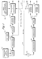
- the source signal is split into first and second signal paths, with a first path being a decoded signal path that in some embodiments may include a delay 22 for delaying the signal temporarily as set forth further below prior to sending the signal to a source decoder 24.
- the source decoder 24 decodes the signal in accordance with, e.g., MPEG principles known in the art to output a decoded (uncompressed) source signal that, if desired, can be processed by, e.g., encrypting it in a processing and encryption module 26 that can be established by, e.g., a processor inside a TV.
- the compressed signal can be designated the primary signal.
- the example shown in Figure 1 uses one compressed and one decoded signal owing to the large bandwidth provided by the non-limiting 60GHz band, both the primary and secondary signals may remain compressed if desired.
- the processing and encryption module 26 may also receive ancillary information such as menu information, user interface information, and user interactions from an ancillary source 28 for combining menus, etc. with the video in the source signal in accordance with TV principles known in the art.
- ancillary information such as menu information, user interface information, and user interactions from an ancillary source 28 for combining menus, etc. with the video in the source signal in accordance with TV principles known in the art.
- the output of the processing module 26 may be provided over, e.g., a wire for presentation on a display 30. It additionally may be desired to wirelessly send the source signal to another device along a high bandwidth path. Accordingly, the output of the processing module 26 can be sent to a first channel encoder 32, for encoding the signal for transmission in accordance with encoding principles known in the art.
- the encoded signal in the first path is sent to a multiplexer 34 for operation to be shortly disclosed, and then to transmission circuitry for transmission.
- the transmission circuitry may include a modulator 36, an upconverter 38, and an antenna 40 in accordance with wireless transmission principles known in the art.
- the transmission circuitry transmits data in the 60GHz band, i.e., at one or more frequencies between about 57GHz and 64GHz. Infrared or other types of high bandwidth transmission paradigms may also be used.
- the source signal after processing by the demodulator 18 is sent along first and second signal paths, with the first signal path having been described above and with the second signal path, as shown in Figure 1 , including a second encoder 42.
- the second encoder 42 encodes the already-compressed source signal and sends it to the multiplexer 34, which multiplexes the signal from the second path with the signal from the first path.
- the encoders 32, 42 shown in Figure 1 are system 10 encoders that function in addition to and separately from encoding that is originally applied in the source 12, so that the second path encodes a version of the source signal that itself has not been previously decoded from its demodulated compressed state.
- the system 10 shown in Figure 1 transmits two versions of the source signal received at the input 14, namely, a compressed error correction version and a decoded primary version, for purposes to be shortly disclosed.
- Figure 1 indicates that a reverse channel 57 may be used to exchange encryption keys between the processing and encryption module 26 in the transmitter and the decryption module 56 in the receiver.
- the reverse channel 57 may be on the same frequency as the forward channel described above, or at a different frequency, e.g., 2.4GHz.
- the primary signal is sent to a switch 58, which may be implemented as a selector in accordance with disclosure below.
- the receiver shown in Figure 1 has two signal paths.
- a second signal path includes a second decoder 60 for processing in reverse to that applied by the second encoder 42 in the transmitter shown in Figure 1 . Then, recalling that the secondary signal in the second path was never decoded in the transmitter from its original compression as received from the source 12, the secondary signal is processed through a source compression decoder 62, which performs the same decoding as the source decoder 24 in the first signal path of the transmitter.
- the primary signal may be delayed in time relative to the secondary signal because of the delay 22 in the first signal path of the transmitter.
- the secondary signal in the second signal path of the receiver is sent to a delay buffer 64 to delay it by the same temporal amount as the primary signal had been delayed in the transmitter, to realign, in time, the primary and secondary signals.
- a packet in the secondary signal having a particular packet ID can arrive substantially simultaneously at the switch 58 as its twin (having the same packet ID) in the primary signal could have arrived in the absence of errors in the primary signal.
- the size of the delay buffer (which might store only a few seconds worth of data) need not be excessive.
- the first channel decoder 54 or other component may detect errors in the primary signal in accordance with error detection principles known in the art, e.g., by examining parity bits. If an error threshold (which may be set at zero) is violated, the decoder 54 (or other component) may send a switching signal along an error status path 65 to the switch 58. When no errors (or errors below a threshold) are present in the primary signal, the switch 58 operates to pass the primary signal to a display 66 for presentation of, e.g., audio/video streams represented by the primary signal. It is to be understood that the display 66 may incorporate a digital to analog converter, or that a DAC may be interposed between the display 66 and the switch 58.
- the error status line signal causes the switch 58 to pass the secondary signal present at its input from the second signal path to the display 66.
- the compressed signal that had been present at the output of the demodulator 18 and encoded by the second encoder 42 in the transmitter, and that is processed along the second path in the receiver as described above, can be used to compensate for errors in the primary signal by substituting out the corrupted portions of the data. Because the transmitter may transmit at 60GHz, sufficient bandwidth is provided in the non-limiting implementation shown for both the HD signal and the compressed signal.
- the delay between the secondary signal and the primary signal can be used to compensate for short periods of signal blocking. Specifically, because packets in the secondary signal are received prior to their counterpart packets in the primary signal, the secondary signal can be used when the primary signal is blocked.
- Figures 2 and 3 respectively show the server and client TV in an alternate embodiment that may be used for, e.g., providing error correction in the case of signals such as standard television signals that may not necessarily be received in a compressed form.
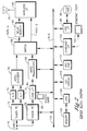
- the server shown in Figure 2 which may be implemented in a set-top box or TV chassis of a home entertainment system, can receive signals from a source such as but not limited to an analog cable source at a signal input 70.
- Analog signals can be tuned and demodulated in an analog tuner/front end component 72, the video output from which can be digitized in a digital analog-to-digital converter (ADC) 74 and then encoded in an MPEG encoder 76.
- ADC digital analog-to-digital converter
- the audio output from the analog tuner/front end component 72 can be digitized in an audio ADC 78 and encoded in the MPEG encoder 76.
- the output stream from the MPEG encoder 76 can be sent to a switch 80.
- the signals may be tuned and demodulated in a digital tuner/front end 82, the output of which, if encrypted for content protection, is decrypted in a Conditional Access Module (CAM) Interface 84 in accordance with decryption information that may be received from, e.g., a portable hand-held access card 86.
- CAM Conditional Access Module
- the decrypted digital stream may be transcoded at another rate if desired in an MPEG transcoder 88 and sent to the switch 80.
- the switch 80 outputs the relevant input stream (either original analog or original digital, depending on what had been received) to first and second signal paths, labelled "Path A" and "Path B" in Figure 2 .
- the switch 80 sends the same input packet along each of two paths to create two streams that are identical to each other. Because, unlike the case in Figure 1 , the two signal streams in Figure 2 are identical, either one may arbitrarily be selected as the "primary" signal and the other designated the "error correction" signal.
- the stream in the first path may be delayed temporarily by a delay 90.
- path "A" in the example shown represents the primary signal.
- a wireless transmission interface 92 receives the two streams and transmits them over an antenna 94 sent to a receiver such as the client TV shown in Figure 3 and described further below.
- the wireless transmission interface 92 which may include a multiplexer, may be a 60GHz transmitter or other transmitter.
- incoming streams may be recorded to, e.g., a hard disk drive (HDD) 96 through a HDD interface 98.
- the incoming streams may be provided to the HDD 96 from the switch 80 or from the MPEG transcoder 88 via an internal data bus 100.
- the recorded stream is sent to the switch 80 and transmitted to a receiver.
- the HDD 96 may store audio/video data downloaded from the Internet through a modem-compatible ethernet port 102 and ethernet interface 104.
- a processor such as a CPU 106 that is connected to the bus 100 controls the components discussed above in accordance with logic that may be embodied in control software in, e.g., an internal solid state or disk memory 108.
- an input device such as a keypad 110 can be provided to send input data to the CPU 106 through the bus 100
- an output device such as an LCD display 112 can be used to indicate data sent from the CPU 106, for example, tuning status, network status, error messages, etc.
- the signals from the server shown in Figure 2 may be received by a receiver such as the client TV shown in Figure 3 .
- the signals are captured at an antenna 114 and processed in accordance with wireless principles known in the art by a wireless receiver interface 116, which outputs the two twin signal streams along first and second paths "A" and "B" that correspond to the "A" and "B” paths, respectively, shown in Figure 2 .
- the output signal representing the delayed stream (Path A) is sent to a switch 118, while the output signal of the non-delayed stream (Path B) is sent to a receiver delay memory 120 that has the same delay time length as the delay memory 90 in the server shown in Figure 2 .
- the output of the receiver delay memory 118 is sent to the switch 118.
- each error-free packet in the stream in Path A is directly output, with an erroneous packet being replaced with the corresponding packet (packet with the same ID or timestamp) in the stream in Path B, which is error-free and hence which is output to render a complete, error free stream (labelled "result" in Figure 4 ).
- errors in packets e.g., numbers N+7 and N+8 in Figure 4
- the stream in path B do not affect the packets in the stream in path A.
- the above stream selection is undertaken by the switch 118 under control of a processor such as a CPU 122 that is connected to the switch 118 over an internal bus 124.
- the CPU 122 may access a logic device such as a disk or solid state memory 126 that contains control software embodying the present logic, so that when an error is detected in accordance with error detection principles known in the art by, e.g., the CPU 122, the CPU 122 can cause the switch 118 to reconfigure to select, for output, the other stream.
- the output of the switch 118 may be demultiplexed in a demultiplexer 128 to separate the audio from the video.
- the audio portion is sent to an audio decoder 130 for analogizing at a digital-to-analog converter (DAC) 132, amplification at an audio amplifier 134, and play on one or more speakers 136.
- the video portion is sent to a video decoder 138 for decoding, then, if desired, to a mixer 140 for mixing with graphics data generated in a graphics engine 142.
- the video is then analogized in a video DAC 144 and sent to a display driver 146, for display on a monitor 148.
- the server CPU and receiver CPU can exchange asynchronous data (commands, data, etc.) over the wireless network shown in Figures 2 and 3 .
- the receiver CPU 122 can control various receiver components through the internal receiver bus 124, and that an IR interface 150 may be provided on the internal receiver bus 124 to receive commands for the CPU 122 from a remote commander 152.
- Figure 5 shows example logic that may be executed by the components above.
- an input signal is received.
- the input signal is split into a primary signal and an secondary signal.
- the primary signal may be delayed if desired at block 158, and then both signals are transmitted at block 160.
- the signals are received at block 162 and if the primary signal was delayed at block 156, the secondary signal is delayed at block 162. If no errors above a non-zero or zero threshold are detected in the primary signal at decision diamond 164, the primary signal is used to display data at block 166. Otherwise, the secondary signal, which, it will be recalled, was received before the corresponding data in the primary signal, is displayed at block 168. The logic then loops back to decision diamond 164.
Landscapes
- Engineering & Computer Science (AREA)
- Multimedia (AREA)
- Signal Processing (AREA)
- Detection And Prevention Of Errors In Transmission (AREA)
- Two-Way Televisions, Distribution Of Moving Picture Or The Like (AREA)
- Compression Or Coding Systems Of Tv Signals (AREA)
Claims (8)
- System (10) zur Fehlerkorrektur in einem komprimierten Quellensignal, das Folgendes umfasst:einen Sender, wobei der Sender Folgendes umfasst:wenigstens einen Quellensignaleingang (14), um das komprimierte Quellensignal zu empfangen;einen ersten Pfad, der mit dem Eingang (14) elektrisch verbunden ist und eine Quellendecodierung des komprimierten Quellensignals ausführt und ein decodiertes, dekomprimiertes Signal an einen Verschlüsseler (26) und einen ersten Kanalcodierer (32) schickt, um einen verschlüsselten primären dekomprimierten Signalstrom zu erzeugen, wobei Verschlüsselungsschlüssel über einen Rückwärtskanal (57) von einem Entschlüsseler (56) eines Empfängers zu dem Verschlüsseler ausgetauscht werden;einen zweiten Pfad, der mit dem Eingang (14) elektrisch verbunden ist, wobei der zweite Pfad einen zweiten Kanalcodierer (42) enthält, um einen nicht verschlüsselten, codierten komprimierten Signalstrom durch Kanalcodierung einer Version des komprimierten Quellensignals, die nicht bereits im Sender aus der ursprünglichen Version quellendecodiert worden ist, zu erzeugen; undeinen Multiplexer (34), um den codierten komprimierten Signalstrom mit dem primären dekomprimierten Signalstrom für dessen Übertragung zu kombinieren.
- System nach Anspruch 1, wobei das komprimierte Quellensignal ein hochauflösendes TV-Signal (HDTV-Signal) ist.
- System nach Anspruch 1, wobei das System auf wenigstens einer Frequenz in einem Spektrum zwischen etwa 57 GHz und 64 GHz sendet.
- System nach Anspruch 1, das wenigstens ein Verzögerungselement (22) in dem ersten Pfad aufweist, das das Codieren decodierter Quellensignaldaten relativ zum Codieren einer komprimierten Version derselben Quellensignaldaten in dem zweiten Pfad verzögert.
- System nach Anspruch 1, das wenigstens einen Empfänger umfasst, um Signale, die von dem Sender geschickt werden, zu empfangen, wobei der Empfänger Folgendes umfasst:einen Demultiplexer (52), um den primären Signalstrom von dem codierten komprimierten Signalstrom zu trennen;eine Schaltungsanordnung (54, 56, 60, 62), um die Ströme zu verarbeiten; undLogik (54, 58), um bei Vorliegen einer ersten Fehlerbedingung Informationen, die in dem primären dekomprimierten Signalstrom geführt werden, anzuzeigen und andernfalls Informationen, die in dem codierten komprimierten Strom geführt werden, anzuzeigen.
- Empfänger drahtlos gesendeter Daten, die angezeigt werden sollen, der Folgendes umfasst:Funksignal-Verarbeitungskomponenten (48, 50, 52, 54, 56, 60, 62), um Signale, die die anzuzeigenden Daten repräsentieren, zu empfangen und zu verarbeiten, wobei die empfangenen Signale wenigstens ein erstes Signal, das die anzuzeigenden Daten repräsentiert, und ein zweites Signal, das die anzuzeigenden Daten repräsentiert, enthalten, wobei das erste Signal eine verschlüsselte, kanalcodierte Version einer quellencodierten, dekomprimierten Version eines komprimierten Quellensignals ist und das zweite Signal eine unverschlüsselte, kanalcodierte Version des komprimierten Quellensignals ist, das nicht bereits in einem Sender aus seiner ursprünglichen Kompression decodiert worden ist, wobei die Funksignal-Verarbeitungskomponenten einen ersten Kanaldecodierer (54) zur Kanaldecodierung des ersten Signals, um die quellendecodierte, dekomprimierte Version des komprimierten Quellensignals in verschlüsselter Form auszugeben, einen Entschlüsseler (56) zum Entschlüsseln der decodierten dekomprimierten Version des komprimierten Quellensignals, wobei Verschlüsselungsschlüssel über einen Rückwärtskanal (57) von dem Entschlüsseler zu einem Verschlüsseler (26) des Senders ausgetauscht werden, einen zweiten Kanaldecodierer (60) zum Kanaldecodieren des zweiten Signals, um die Version des komprimierten Quellensignals auszugeben, das nicht bereits in dem Sender quellendecodiert worden ist, und einen Quellendecodierer (62), um an der Version des komprimierten Quellensignals von dem zweiten Kanaldecodierer (60) eine Quellendecodierung auszuführen, um ein decodiertes dekomprimiertes Signal auszugeben, umfassen;eine Verzögerungskomponente (64), um das zweite Signal vorübergehend zu halten; undLogik (54, 58), um zu bestimmen, ob das erste Signal eine Fehlerbedingung verletzt, und wenn ja, Informationen, die durch einen Fehler in dem ersten Signal beeinflusst werden, durch Informationen zu ersetzen, die in dem zweiten Signal geführt werden.
- Empfänger nach Anspruch 6, wobei das komprimierte Quellensignal ein HDTV-Signal ist.
- Empfänger nach Anspruch 7, wobei der Empfänger Signale in dem 60 GHZ-Band empfängt.
Applications Claiming Priority (2)
| Application Number | Priority Date | Filing Date | Title |
|---|---|---|---|
| US11/062,142 US7653869B2 (en) | 2005-02-18 | 2005-02-18 | System and method for error correction in high definition TV signal |
| PCT/US2006/001128 WO2006091282A2 (en) | 2005-02-18 | 2006-01-12 | System and method for error correction in high definition tv signal |
Publications (3)
| Publication Number | Publication Date |
|---|---|
| EP1849306A2 EP1849306A2 (de) | 2007-10-31 |
| EP1849306A4 EP1849306A4 (de) | 2010-03-24 |
| EP1849306B1 true EP1849306B1 (de) | 2014-04-16 |
Family
ID=36914268
Family Applications (1)
| Application Number | Title | Priority Date | Filing Date |
|---|---|---|---|
| EP06718225.3A Ceased EP1849306B1 (de) | 2005-02-18 | 2006-01-12 | System und verfahren zur fehlerkorrektur bei einem hochauflösendem tv-signal |
Country Status (7)
| Country | Link |
|---|---|
| US (1) | US7653869B2 (de) |
| EP (1) | EP1849306B1 (de) |
| JP (1) | JP5297043B2 (de) |
| KR (1) | KR101244072B1 (de) |
| CN (1) | CN101124827B (de) |
| CA (1) | CA2597180C (de) |
| WO (1) | WO2006091282A2 (de) |
Families Citing this family (16)
| Publication number | Priority date | Publication date | Assignee | Title |
|---|---|---|---|---|
| JP5268636B2 (ja) * | 2006-04-27 | 2013-08-21 | 三菱電機株式会社 | 再生装置及び再生方法 |
| JP2008199175A (ja) * | 2007-02-09 | 2008-08-28 | Nec Electronics Corp | 信号処理装置 |
| US8041333B2 (en) * | 2007-06-14 | 2011-10-18 | Broadcom Corporation | Method and system for 60 GHz antenna adaptation and user coordination based on base station beacons |
| US8375305B1 (en) | 2010-05-14 | 2013-02-12 | Amazon Technologies, Inc. | Placement of user interface elements based on a window entry or exit point |
| US10616184B2 (en) * | 2016-06-30 | 2020-04-07 | Intel Corporation | Wireless display streaming of protected content |
| US10060857B1 (en) | 2017-11-16 | 2018-08-28 | General Electric Company | Robotic feature mapping and motion control |
| US11504853B2 (en) | 2017-11-16 | 2022-11-22 | General Electric Company | Robotic system architecture and control processes |
| US10999304B2 (en) | 2018-04-11 | 2021-05-04 | Palo Alto Networks (Israel Analytics) Ltd. | Bind shell attack detection |
| US11184376B2 (en) * | 2019-01-30 | 2021-11-23 | Palo Alto Networks (Israel Analytics) Ltd. | Port scan detection using destination profiles |
| US11184377B2 (en) | 2019-01-30 | 2021-11-23 | Palo Alto Networks (Israel Analytics) Ltd. | Malicious port scan detection using source profiles |
| US11316872B2 (en) | 2019-01-30 | 2022-04-26 | Palo Alto Networks (Israel Analytics) Ltd. | Malicious port scan detection using port profiles |
| US11184378B2 (en) | 2019-01-30 | 2021-11-23 | Palo Alto Networks (Israel Analytics) Ltd. | Scanner probe detection |
| US12039017B2 (en) | 2021-10-20 | 2024-07-16 | Palo Alto Networks (Israel Analytics) Ltd. | User entity normalization and association |
| US11799880B2 (en) | 2022-01-10 | 2023-10-24 | Palo Alto Networks (Israel Analytics) Ltd. | Network adaptive alert prioritization system |
| US12603896B2 (en) | 2022-02-21 | 2026-04-14 | Palo Alto Networks, Inc. | Agent prevention augmentation based on organizational learning |
| US12615282B2 (en) | 2023-07-23 | 2026-04-28 | Palo Alto Networks, Inc. | Security incident ranking and ranking explanation |
Citations (1)
| Publication number | Priority date | Publication date | Assignee | Title |
|---|---|---|---|---|
| EP1501227A1 (de) * | 2002-04-26 | 2005-01-26 | NEC Corporation | Audiodatencodeumsetzungs-übertragungsverfahren und codeumsetzungs-empfangsverfahren, einrichtung, system und programm |
Family Cites Families (27)
| Publication number | Priority date | Publication date | Assignee | Title |
|---|---|---|---|---|
| JP2751201B2 (ja) * | 1988-04-19 | 1998-05-18 | ソニー株式会社 | データ伝送装置及び受信装置 |
| JP2590644B2 (ja) * | 1991-09-13 | 1997-03-12 | 日本電気株式会社 | 無線通信装置及び試験送信機 |
| USRE38513E1 (en) * | 1992-03-26 | 2004-05-11 | Matsushita Electric Industrial Co., Ltd. | Communication system |
| US5566208A (en) * | 1994-03-17 | 1996-10-15 | Philips Electronics North America Corp. | Encoder buffer having an effective size which varies automatically with the channel bit-rate |
| US5621467A (en) * | 1995-02-16 | 1997-04-15 | Thomson Multimedia S.A. | Temporal-spatial error concealment apparatus and method for video signal processors |
| US5592471A (en) * | 1995-04-21 | 1997-01-07 | Cd Radio Inc. | Mobile radio receivers using time diversity to avoid service outages in multichannel broadcast transmission systems |
| US6070141A (en) * | 1995-05-08 | 2000-05-30 | Image Data, Llc | System and method of assessing the quality of an identification transaction using an identificaion quality score |
| US5663726A (en) * | 1995-12-01 | 1997-09-02 | U.S. Philips Corporation | High speed variable-length decoder arrangement with reduced memory requirements for tag stream buffering |
| JP3974712B2 (ja) * | 1998-08-31 | 2007-09-12 | 富士通株式会社 | ディジタル放送用送信・受信再生方法及びディジタル放送用送信・受信再生システム並びにディジタル放送用送信装置及びディジタル放送用受信再生装置 |
| US6263023B1 (en) * | 1998-10-15 | 2001-07-17 | International Business Machines Corporation | High definition television decoder |
| US7016337B1 (en) * | 1999-03-02 | 2006-03-21 | Cisco Technology, Inc. | System and method for multiple channel statistical re-multiplexing |
| US6594798B1 (en) | 1999-05-21 | 2003-07-15 | Microsoft Corporation | Receiver-driven layered error correction multicast over heterogeneous packet networks |
| US6728924B1 (en) * | 1999-10-21 | 2004-04-27 | Lucent Technologies Inc. | Packet loss control method for real-time multimedia communications |
| FR2803459B1 (fr) | 1999-12-30 | 2002-02-15 | Itis | Systeme de transmission a diversite spatiale, temporelle et frequentielle |
| US6610749B2 (en) * | 2000-02-18 | 2003-08-26 | Arch Development Corporation | Polyhydroxylated benzene-containing compounds |
| TW506194B (en) * | 2000-03-27 | 2002-10-11 | Sanyo Electric Co | Error detection and correction circuit |
| US7248158B2 (en) * | 2000-04-14 | 2007-07-24 | Current Technologies, Llc | Automated meter reading power line communication system and method |
| JPWO2003030534A1 (ja) * | 2001-09-28 | 2005-01-20 | 松下電器産業株式会社 | デジタル放送用送受信システム |
| EP1501310A4 (de) * | 2002-04-26 | 2012-07-11 | Nec Corp | Datencodeumsetzungs-/-übertragungsverfahren und einrichtung für bewegliche bilder, codeumsetzungs-/-empfangsverfahren und einrichtung |
| US7127669B2 (en) | 2002-05-31 | 2006-10-24 | Kiribati Wireless Ventures, Llc | Redundant path communication methods and systems |
| US7296211B2 (en) * | 2002-06-25 | 2007-11-13 | Lockheed Martin Corporation | System and method for transferring data on a data link |
| US20040022231A1 (en) * | 2002-07-30 | 2004-02-05 | John Morrish | Time diversity techniques |
| US20040120404A1 (en) * | 2002-11-27 | 2004-06-24 | Takayuki Sugahara | Variable length data encoding method, variable length data encoding apparatus, variable length encoded data decoding method, and variable length encoded data decoding apparatus |
| US20040139477A1 (en) * | 2003-01-15 | 2004-07-15 | Russell David B. | 60 GHz RF CATV repeater |
| US7643558B2 (en) | 2003-03-24 | 2010-01-05 | Qualcomm Incorporated | Method, apparatus, and system for encoding and decoding side information for multimedia transmission |
| US7965837B2 (en) | 2003-04-30 | 2011-06-21 | Sony Corporation | Method and system for wireless digital video presentation |
| US7359409B2 (en) * | 2005-02-02 | 2008-04-15 | Texas Instruments Incorporated | Packet loss concealment for voice over packet networks |
-
2005
- 2005-02-18 US US11/062,142 patent/US7653869B2/en not_active Expired - Fee Related
-
2006
- 2006-01-12 CN CN2006800054240A patent/CN101124827B/zh not_active Expired - Fee Related
- 2006-01-12 JP JP2007556143A patent/JP5297043B2/ja not_active Expired - Fee Related
- 2006-01-12 EP EP06718225.3A patent/EP1849306B1/de not_active Ceased
- 2006-01-12 WO PCT/US2006/001128 patent/WO2006091282A2/en not_active Ceased
- 2006-01-12 CA CA2597180A patent/CA2597180C/en not_active Expired - Lifetime
- 2006-01-12 KR KR1020077018930A patent/KR101244072B1/ko not_active Expired - Fee Related
Patent Citations (1)
| Publication number | Priority date | Publication date | Assignee | Title |
|---|---|---|---|---|
| EP1501227A1 (de) * | 2002-04-26 | 2005-01-26 | NEC Corporation | Audiodatencodeumsetzungs-übertragungsverfahren und codeumsetzungs-empfangsverfahren, einrichtung, system und programm |
Also Published As
| Publication number | Publication date |
|---|---|
| CN101124827B (zh) | 2010-06-16 |
| JP2008530950A (ja) | 2008-08-07 |
| US7653869B2 (en) | 2010-01-26 |
| CA2597180A1 (en) | 2006-08-31 |
| KR101244072B1 (ko) | 2013-03-18 |
| WO2006091282A2 (en) | 2006-08-31 |
| CN101124827A (zh) | 2008-02-13 |
| WO2006091282A3 (en) | 2007-07-12 |
| CA2597180C (en) | 2014-02-25 |
| EP1849306A4 (de) | 2010-03-24 |
| KR20070103460A (ko) | 2007-10-23 |
| US20060190803A1 (en) | 2006-08-24 |
| EP1849306A2 (de) | 2007-10-31 |
| JP5297043B2 (ja) | 2013-09-25 |
Similar Documents
| Publication | Publication Date | Title |
|---|---|---|
| CA2597180C (en) | System and method for error correction in high definition tv signal | |
| US7953442B2 (en) | Method and system for processing wireless digital multimedia | |
| US20080240230A1 (en) | Media processor with an integrated TV receiver | |
| JP2006041848A (ja) | 受信装置および受信方法 | |
| US20080098451A1 (en) | Digital broadcasting receiver and scambled channel determination method thereof | |
| KR100661253B1 (ko) | 수신장치 및 수신 복호방법 | |
| EP2946564B1 (de) | Anordnung zur drahtlosen übertragung eines mpeg2-ts-kompatiblen datenstroms | |
| US12155886B2 (en) | Efficient media stream encryption providing full content protection | |
| KR20210007571A (ko) | Csa 복호모듈을 이용한 복호시스템의 구현방법 | |
| JP3778067B2 (ja) | デジタル放送受信システム | |
| JP2002176594A (ja) | デジタル放送受信装置 | |
| US20080060015A1 (en) | Digital Broadcast Reception System | |
| JP4361340B2 (ja) | デジタルテレビ受信機 | |
| KR100681639B1 (ko) | 디지털 멀티미디어 방송 시스템의 방송 데이터 처리 장치및 방법 | |
| JP7573217B2 (ja) | 映像信号処理装置、映像信号処理方法、プログラムおよび信号処理回路 | |
| KR20130114422A (ko) | 지상파 uhdtv 방송수신기 및 지상파 uhdtv 전송신호 분석기 | |
| WO2007058067A1 (ja) | 携帯通信端末、デジタル放送補完装置、およびデジタル放送補完システム | |
| US9641873B1 (en) | Method and apparatus for controlling broadcast programming content | |
| KR100531339B1 (ko) | 위성방송 수신기의 통합형 복호장치 | |
| JP2009021806A (ja) | デジタル放送コンテンツ出力方法、デジタル放送コンテンツ出力システム及びデジタル放送コンテンツ出力装置 | |
| JP2010171486A (ja) | 情報配信システム、情報配信装置、情報受信装置、情報配信方法、並びに情報受信方法 | |
| KR20070017498A (ko) | 신호를 제공하는 방법 및 시스템 | |
| KR20100089282A (ko) | 영상신호 송수신 장치 | |
| JP2010200173A (ja) | 情報配信システム、情報受信装置並びに情報受信方法 | |
| KR19990075945A (ko) | 위성 방송 시스템의 서비스 데이터 처리 방법 |
Legal Events
| Date | Code | Title | Description |
|---|---|---|---|
| PUAI | Public reference made under article 153(3) epc to a published international application that has entered the european phase |
Free format text: ORIGINAL CODE: 0009012 |
|
| 17P | Request for examination filed |
Effective date: 20070801 |
|
| AK | Designated contracting states |
Kind code of ref document: A2 Designated state(s): AT BE BG CH CY CZ DE DK EE ES FI FR GB GR HU IE IS IT LI LT LU LV MC NL PL PT RO SE SI SK TR |
|
| AX | Request for extension of the european patent |
Extension state: AL BA HR MK YU |
|
| RIN1 | Information on inventor provided before grant (corrected) |
Inventor name: IWAMURA, RYUICHI Inventor name: KAWASKI, KENICHI |
|
| DAX | Request for extension of the european patent (deleted) | ||
| RBV | Designated contracting states (corrected) |
Designated state(s): DE FR GB |
|
| RBV | Designated contracting states (corrected) |
Designated state(s): DE FR GB |
|
| A4 | Supplementary search report drawn up and despatched |
Effective date: 20100219 |
|
| 17Q | First examination report despatched |
Effective date: 20100420 |
|
| GRAP | Despatch of communication of intention to grant a patent |
Free format text: ORIGINAL CODE: EPIDOSNIGR1 |
|
| RIC1 | Information provided on ipc code assigned before grant |
Ipc: H04N 7/68 20060101AFI20131018BHEP Ipc: H04N 7/64 20060101ALI20131018BHEP Ipc: H04N 7/26 20060101ALI20131018BHEP Ipc: H04N 21/436 20110101ALI20131018BHEP |
|
| INTG | Intention to grant announced |
Effective date: 20131106 |
|
| GRAS | Grant fee paid |
Free format text: ORIGINAL CODE: EPIDOSNIGR3 |
|
| REG | Reference to a national code |
Ref country code: DE Ref legal event code: R079 Ref document number: 602006041083 Country of ref document: DE Free format text: PREVIOUS MAIN CLASS: H04N0007680000 Ipc: H04N0019300000 |
|
| GRAA | (expected) grant |
Free format text: ORIGINAL CODE: 0009210 |
|
| AK | Designated contracting states |
Kind code of ref document: B1 Designated state(s): DE FR GB |
|
| REG | Reference to a national code |
Ref country code: GB Ref legal event code: FG4D |
|
| RIC1 | Information provided on ipc code assigned before grant |
Ipc: H04N 19/30 20140101AFI20140310BHEP Ipc: H04N 21/436 20110101ALI20140310BHEP Ipc: H04N 19/89 20140101ALI20140310BHEP |
|
| REG | Reference to a national code |
Ref country code: DE Ref legal event code: R096 Ref document number: 602006041083 Country of ref document: DE Effective date: 20140522 |
|
| REG | Reference to a national code |
Ref country code: DE Ref legal event code: R097 Ref document number: 602006041083 Country of ref document: DE |
|
| PLBE | No opposition filed within time limit |
Free format text: ORIGINAL CODE: 0009261 |
|
| STAA | Information on the status of an ep patent application or granted ep patent |
Free format text: STATUS: NO OPPOSITION FILED WITHIN TIME LIMIT |
|
| 26N | No opposition filed |
Effective date: 20150119 |
|
| REG | Reference to a national code |
Ref country code: DE Ref legal event code: R097 Ref document number: 602006041083 Country of ref document: DE Effective date: 20150119 |
|
| REG | Reference to a national code |
Ref country code: FR Ref legal event code: PLFP Year of fee payment: 11 |
|
| REG | Reference to a national code |
Ref country code: DE Ref legal event code: R084 Ref document number: 602006041083 Country of ref document: DE |
|
| REG | Reference to a national code |
Ref country code: GB Ref legal event code: 746 Effective date: 20160413 |
|
| REG | Reference to a national code |
Ref country code: FR Ref legal event code: PLFP Year of fee payment: 12 |
|
| REG | Reference to a national code |
Ref country code: FR Ref legal event code: PLFP Year of fee payment: 13 |
|
| PGFP | Annual fee paid to national office [announced via postgrant information from national office to epo] |
Ref country code: DE Payment date: 20201217 Year of fee payment: 16 |
|
| REG | Reference to a national code |
Ref country code: DE Ref legal event code: R119 Ref document number: 602006041083 Country of ref document: DE |
|
| PG25 | Lapsed in a contracting state [announced via postgrant information from national office to epo] |
Ref country code: DE Free format text: LAPSE BECAUSE OF NON-PAYMENT OF DUE FEES Effective date: 20220802 |
|
| P01 | Opt-out of the competence of the unified patent court (upc) registered |
Effective date: 20230606 |
|
| PGFP | Annual fee paid to national office [announced via postgrant information from national office to epo] |
Ref country code: GB Payment date: 20231219 Year of fee payment: 19 |
|
| PGFP | Annual fee paid to national office [announced via postgrant information from national office to epo] |
Ref country code: FR Payment date: 20231219 Year of fee payment: 19 |
|
| GBPC | Gb: european patent ceased through non-payment of renewal fee |
Effective date: 20250112 |
|
| PG25 | Lapsed in a contracting state [announced via postgrant information from national office to epo] |
Ref country code: GB Free format text: LAPSE BECAUSE OF NON-PAYMENT OF DUE FEES Effective date: 20250112 |
|
| PG25 | Lapsed in a contracting state [announced via postgrant information from national office to epo] |
Ref country code: FR Free format text: LAPSE BECAUSE OF NON-PAYMENT OF DUE FEES Effective date: 20250131 |