EP1848578B1 - Apparatus for sealing flex circuits having heat sensitive circuit elements - Google Patents
Apparatus for sealing flex circuits having heat sensitive circuit elements Download PDFInfo
- Publication number
- EP1848578B1 EP1848578B1 EP06719889A EP06719889A EP1848578B1 EP 1848578 B1 EP1848578 B1 EP 1848578B1 EP 06719889 A EP06719889 A EP 06719889A EP 06719889 A EP06719889 A EP 06719889A EP 1848578 B1 EP1848578 B1 EP 1848578B1
- Authority
- EP
- European Patent Office
- Prior art keywords
- circuit elements
- substrate
- cover layer
- press
- conduits
- Prior art date
- Legal status (The legal status is an assumption and is not a legal conclusion. Google has not performed a legal analysis and makes no representation as to the accuracy of the status listed.)
- Active
Links
Images

Classifications
-
- H—ELECTRICITY
- H05—ELECTRIC TECHNIQUES NOT OTHERWISE PROVIDED FOR
- H05K—PRINTED CIRCUITS; CASINGS OR CONSTRUCTIONAL DETAILS OF ELECTRIC APPARATUS; MANUFACTURE OF ASSEMBLAGES OF ELECTRICAL COMPONENTS
- H05K3/00—Apparatus or processes for manufacturing printed circuits
- H05K3/30—Assembling printed circuits with electric components, e.g. with resistor
-
- B—PERFORMING OPERATIONS; TRANSPORTING
- B32—LAYERED PRODUCTS
- B32B—LAYERED PRODUCTS, i.e. PRODUCTS BUILT-UP OF STRATA OF FLAT OR NON-FLAT, e.g. CELLULAR OR HONEYCOMB, FORM
- B32B37/00—Methods or apparatus for laminating, e.g. by curing or by ultrasonic bonding
- B32B37/06—Methods or apparatus for laminating, e.g. by curing or by ultrasonic bonding characterised by the heating method
-
- B—PERFORMING OPERATIONS; TRANSPORTING
- B32—LAYERED PRODUCTS
- B32B—LAYERED PRODUCTS, i.e. PRODUCTS BUILT-UP OF STRATA OF FLAT OR NON-FLAT, e.g. CELLULAR OR HONEYCOMB, FORM
- B32B37/00—Methods or apparatus for laminating, e.g. by curing or by ultrasonic bonding
- B32B37/08—Methods or apparatus for laminating, e.g. by curing or by ultrasonic bonding characterised by the cooling method
-
- B—PERFORMING OPERATIONS; TRANSPORTING
- B32—LAYERED PRODUCTS
- B32B—LAYERED PRODUCTS, i.e. PRODUCTS BUILT-UP OF STRATA OF FLAT OR NON-FLAT, e.g. CELLULAR OR HONEYCOMB, FORM
- B32B37/00—Methods or apparatus for laminating, e.g. by curing or by ultrasonic bonding
- B32B37/10—Methods or apparatus for laminating, e.g. by curing or by ultrasonic bonding characterised by the pressing technique, e.g. using action of vacuum or fluid pressure
- B32B37/1009—Methods or apparatus for laminating, e.g. by curing or by ultrasonic bonding characterised by the pressing technique, e.g. using action of vacuum or fluid pressure using vacuum and fluid pressure
-
- H—ELECTRICITY
- H05—ELECTRIC TECHNIQUES NOT OTHERWISE PROVIDED FOR
- H05K—PRINTED CIRCUITS; CASINGS OR CONSTRUCTIONAL DETAILS OF ELECTRIC APPARATUS; MANUFACTURE OF ASSEMBLAGES OF ELECTRICAL COMPONENTS
- H05K3/00—Apparatus or processes for manufacturing printed circuits
- H05K3/22—Secondary treatment of printed circuits
- H05K3/28—Applying non-metallic protective coatings
- H05K3/284—Applying non-metallic protective coatings for encapsulating mounted components
-
- B—PERFORMING OPERATIONS; TRANSPORTING
- B32—LAYERED PRODUCTS
- B32B—LAYERED PRODUCTS, i.e. PRODUCTS BUILT-UP OF STRATA OF FLAT OR NON-FLAT, e.g. CELLULAR OR HONEYCOMB, FORM
- B32B2305/00—Condition, form or state of the layers or laminate
- B32B2305/55—Liquid crystals
-
- B—PERFORMING OPERATIONS; TRANSPORTING
- B32—LAYERED PRODUCTS
- B32B—LAYERED PRODUCTS, i.e. PRODUCTS BUILT-UP OF STRATA OF FLAT OR NON-FLAT, e.g. CELLULAR OR HONEYCOMB, FORM
- B32B2309/00—Parameters for the laminating or treatment process; Apparatus details
- B32B2309/02—Temperature
-
- B—PERFORMING OPERATIONS; TRANSPORTING
- B32—LAYERED PRODUCTS
- B32B—LAYERED PRODUCTS, i.e. PRODUCTS BUILT-UP OF STRATA OF FLAT OR NON-FLAT, e.g. CELLULAR OR HONEYCOMB, FORM
- B32B2457/00—Electrical equipment
- B32B2457/08—PCBs, i.e. printed circuit boards
-
- B—PERFORMING OPERATIONS; TRANSPORTING
- B32—LAYERED PRODUCTS
- B32B—LAYERED PRODUCTS, i.e. PRODUCTS BUILT-UP OF STRATA OF FLAT OR NON-FLAT, e.g. CELLULAR OR HONEYCOMB, FORM
- B32B37/00—Methods or apparatus for laminating, e.g. by curing or by ultrasonic bonding
- B32B37/04—Methods or apparatus for laminating, e.g. by curing or by ultrasonic bonding characterised by the partial melting of at least one layer
-
- B—PERFORMING OPERATIONS; TRANSPORTING
- B32—LAYERED PRODUCTS
- B32B—LAYERED PRODUCTS, i.e. PRODUCTS BUILT-UP OF STRATA OF FLAT OR NON-FLAT, e.g. CELLULAR OR HONEYCOMB, FORM
- B32B37/00—Methods or apparatus for laminating, e.g. by curing or by ultrasonic bonding
- B32B37/14—Methods or apparatus for laminating, e.g. by curing or by ultrasonic bonding characterised by the properties of the layers
- B32B37/16—Methods or apparatus for laminating, e.g. by curing or by ultrasonic bonding characterised by the properties of the layers with all layers existing as coherent layers before laminating
- B32B37/18—Methods or apparatus for laminating, e.g. by curing or by ultrasonic bonding characterised by the properties of the layers with all layers existing as coherent layers before laminating involving the assembly of discrete sheets or panels only
- B32B37/182—Methods or apparatus for laminating, e.g. by curing or by ultrasonic bonding characterised by the properties of the layers with all layers existing as coherent layers before laminating involving the assembly of discrete sheets or panels only one or more of the layers being plastic
- B32B37/185—Laminating sheets, panels or inserts between two discrete plastic layers
-
- H—ELECTRICITY
- H05—ELECTRIC TECHNIQUES NOT OTHERWISE PROVIDED FOR
- H05K—PRINTED CIRCUITS; CASINGS OR CONSTRUCTIONAL DETAILS OF ELECTRIC APPARATUS; MANUFACTURE OF ASSEMBLAGES OF ELECTRICAL COMPONENTS
- H05K1/00—Printed circuits
- H05K1/18—Printed circuits structurally associated with non-printed electric components
- H05K1/189—Printed circuits structurally associated with non-printed electric components characterised by the use of a flexible or folded printed circuit
-
- H—ELECTRICITY
- H05—ELECTRIC TECHNIQUES NOT OTHERWISE PROVIDED FOR
- H05K—PRINTED CIRCUITS; CASINGS OR CONSTRUCTIONAL DETAILS OF ELECTRIC APPARATUS; MANUFACTURE OF ASSEMBLAGES OF ELECTRICAL COMPONENTS
- H05K2201/00—Indexing scheme relating to printed circuits covered by H05K1/00
- H05K2201/06—Thermal details
- H05K2201/064—Fluid cooling, e.g. by integral pipes
-
- H—ELECTRICITY
- H05—ELECTRIC TECHNIQUES NOT OTHERWISE PROVIDED FOR
- H05K—PRINTED CIRCUITS; CASINGS OR CONSTRUCTIONAL DETAILS OF ELECTRIC APPARATUS; MANUFACTURE OF ASSEMBLAGES OF ELECTRICAL COMPONENTS
- H05K2203/00—Indexing scheme relating to apparatus or processes for manufacturing printed circuits covered by H05K3/00
- H05K2203/06—Lamination
- H05K2203/068—Features of the lamination press or of the lamination process, e.g. using special separator sheets
-
- H—ELECTRICITY
- H05—ELECTRIC TECHNIQUES NOT OTHERWISE PROVIDED FOR
- H05K—PRINTED CIRCUITS; CASINGS OR CONSTRUCTIONAL DETAILS OF ELECTRIC APPARATUS; MANUFACTURE OF ASSEMBLAGES OF ELECTRICAL COMPONENTS
- H05K2203/00—Indexing scheme relating to apparatus or processes for manufacturing printed circuits covered by H05K3/00
- H05K2203/11—Treatments characterised by their effect, e.g. heating, cooling, roughening
- H05K2203/1121—Cooling, e.g. specific areas of a PCB being cooled during reflow soldering
-
- H—ELECTRICITY
- H05—ELECTRIC TECHNIQUES NOT OTHERWISE PROVIDED FOR
- H05K—PRINTED CIRCUITS; CASINGS OR CONSTRUCTIONAL DETAILS OF ELECTRIC APPARATUS; MANUFACTURE OF ASSEMBLAGES OF ELECTRICAL COMPONENTS
- H05K2203/00—Indexing scheme relating to apparatus or processes for manufacturing printed circuits covered by H05K3/00
- H05K2203/13—Moulding and encapsulation; Deposition techniques; Protective layers
- H05K2203/1305—Moulding and encapsulation
- H05K2203/1311—Foil encapsulation, e.g. of mounted components
-
- H—ELECTRICITY
- H05—ELECTRIC TECHNIQUES NOT OTHERWISE PROVIDED FOR
- H05K—PRINTED CIRCUITS; CASINGS OR CONSTRUCTIONAL DETAILS OF ELECTRIC APPARATUS; MANUFACTURE OF ASSEMBLAGES OF ELECTRICAL COMPONENTS
- H05K2203/00—Indexing scheme relating to apparatus or processes for manufacturing printed circuits covered by H05K3/00
- H05K2203/30—Details of processes not otherwise provided for in H05K2203/01 - H05K2203/17
- H05K2203/304—Protecting a component during manufacturing
Definitions
- This invention is directed to flexible circuits, and, more particularly, to an apparatus for sealing circuit elements of a flexible circuit, including heat sensitive circuit elements, which are mounted on a substrate formed of liquid crystal polymer to protect them from exposure to moisture and contaminants.
- Flex circuits are used in a wide variety of applications where an electrical circuit must bend around corners or be flexed during operation. Flex circuits are thin, light weight, flexible and exhibit high routability. Traditionally, polyimide films have been used as substrates in the manufacture of flex circuits due to their good thermal stability and mechanical strength. Other properties of polyimide films, however, limit the speed or frequency at which electric components mounted thereto can operate.
- LCP Liquid crystal polymer
- LCP is a thermoplastic aromatic polyester which is thermally stable, with an upper use temperature in excess of 250°C and good inherent flame retardant properties.
- LCP films in comparison to polyimide films, have about one-tenth of the moisture uptake and a lower coefficient of humidity expansion. Lower moisture absorption leads to higher frequency signal and data processing stability. Additionally, LCP films have a lower dielectric constant and a lower loss or dissipation factor over the functional frequency range of 1kHz to 45 GHz, with negligible moisture effects, compared to polyimide films.
- a failure of the seal between the cover layer and substrate at any point along the periphery of the flex circuit can expose all of the circuit elements to moisture, chemicals or other contaminants. If the air between the cover layer and substrate is not fully removed, pressurization of the flex circuit which would occur in underwater applications, for example, could compress such air and create a bubble potentially resulting in a rupture of the cover layer and/or substrate thus creating a failure of the entire circuit.
- the melt temperature of LCP material is approximately 283°C, and soldermask coatings are also applied at relatively high temperatures. While a number of standard circuit elements are not affected by high temperatures, components such as micro-electrical-mechanical-system (“MEMS") sensors, infra-red sensors and a variety of other circuit elements are temperature sensitive and can be damaged or destroyed upon exposure to elevated temperatures.
- MEMS micro-electrical-mechanical-system
- DE 199 20 577 discloses a pressing apparatus for coating a piece through a membrane press.
- Such an apparatus comprises: a container for warm liquid and a container for cold liquid; a press with two membranes and for forming two different chambers; a support carrying a piece covered with covering material; conduits between the containers and the first chamber.
- a first operation step the warm liquid flows into the first chamber so as the high temperature causes the piece to be coated by the material.
- the warm liquid is sucked from the first chamber; the cold liquid flows into the first chamber.
- the second chamber is configured for containing compressed air in different operation steps.
- This invention is directed to an apparatus for affixing an LCP cover layer to a flex circuit consisting of circuit elements mounted to an LCP substrate, at least some of which are temperature sensitive, in order to individually protect the circuit elements from damage and/or reduced operational efficiency due to the presence of moisture, chemical and other contaminants.
- the apparatus includes an iso-static press having a hollow interior connected to a source of oil or other liquid whose temperature can be accurately controlled and maintained.
- the oil is heated to a temperature in the range of approximately 283°C to 320°C and transferred from a reservoir into the interior of the press.
- the base of the press has a plate or membrane formed of a flexible material covered with a non-stick surface which does not adhere to LCP.
- the flex circuit is placed on the surface of the thermally conductive top plate of a support such that the circuit elements are exposed.
- a thermal insulating compound may be placed over each temperature sensitive circuit element for added thermal protection.
- the support includes a housing formed with a cavity within which a number of conduits are mounted each having an upper end communicating with a channel formed in the underside of the top plate. Cooling fluid from a source is circulated through selected conduits, i.e. those which are located beneath the temperature sensitive circuit elements of the flex circuit, to provide localized cooling of such elements during the lamination process. Other conduits, which are not located near the temperature sensitive circuit elements, may be supplied with a heating fluid to raise the temperature of the top plate of the support in selected areas and thus assist with the lamination process.
- an LCP cover layer is placed atop the flex circuit and the press is activated to move into contact with the cover layer.
- the flexible membrane at the base of the press is capable of substantially conforming to the shape of the circuit elements, thus urging the LCP cover layer around each of them individually to the underlying LCP substrate of the flex circuit.
- the temperature and pressure applied by the press, and the elevated temperature of selected areas of the support top plate, are sufficient to cause the LCP cover layer and substrate to "relax" or melt to a limited extent and thus adhere together forming a secure bond so that the circuit elements are individually encapsulated between the two layers.
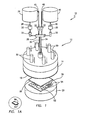
- the apparatus 10 includes an iso-static press 12 having a housing 14 formed with a hollow interior.
- the base of the housing 14 mounts a flexible membrane 16 having an exposed surface coated with Teflon® or other release agent which will not stick to LCP, and an inside surface coated with a hydrophobic film.
- the flexible membrane 16 is formed of high density polyethylene, butyl rubber, ethylene propylene diene monomer rubber or a similar material.
- the press 12 is operative to apply heat and pressure against a cover layer 18 which overlies a flex circuit 20 placed upon a support 22.
- the press 12 is heated by the introduction into its hollow interior of heated oil or a similar fluid whose temperature can be relatively accurately controlled and maintained within the range of about 283°C to 320°C.
- a first reservoir 24 having heating elements (not shown) is connected by a supply line 26 to a manifold 28.
- a pump 30 and valve 32 are located in the supply line 26, between the first reservoir 24 and manifold 28, as shown.
- the manifold 28, in turn, is connected by an input line 34 to one port at the top of the press 12, and by an output line 38 to a second port.
- a recirculation line 42, containing a valve 32, is connected between the manifold 28 and the top of the first reservoir 24.
- a second reservoir 44 which contains the same fluid as first reservoir 24 except at ambient temperature.
- the bottom of second reservoir 44 is connected by a line 46 to the manifold 28, and a recirculation line 48 connects the manifold 28 to the top of the second reservoir 44.
- a pump 30 and valve 32 are located in the line 46 between the second reservoir 44 and manifold 28, and a valve 32 is mounted in the recirculation line 48.
- the press 12 is moved with respect to the support 22 by a number of pneumatic or hydraulic pistons 50 which are mounted at equal intervals along the top surface of the press 12.
- the pistons 50 are independently actuated by a source of air or fluid (not shown) to ensure that the press 12 applies uniform pressure to the cover layer 18 and flex circuit 20 over the entire surface area of the flexible membrane 16.
- the detailed construction of the press 12 forms no part of this invention, and is therefore not discussed further herein.
- the method and apparatus 10 of this invention are designed to provide a means for individually encapsulating circuit elements to protect them from moisture and contaminants.
- the flex circuit 20 consists of a substrate 52 formed of LCP - upon which a number of circuit elements 54 are mounted.
- the cover layer 18 is also formed of LCP, which, because of its thermoplastic nature, will "relax" or begin to melt at a temperature of about 283°C. By placing the cover layer 18 over the flex circuit 20 and applying heat and pressure, the cover layer 18 and substrate 52 adhere to one another with a secure bond and entirely enclose the circuit elements 54 between them.
- the support 22 is constructed to provide localized cooling of the temperature sensitive circuit elements 54, and to generate heat in other areas of the substrate 52 which raises its temperature to assist with the lamination or encapsulation process.
- the support 22 includes a side wall 56 defining an internal cavity 58 which is closed by a top plate 60 and a bottom plate 62.
- the top plate 60 is preferably formed of a highly thermally conductive material such as aluminum silica carbide.
- a number of channels 64 are machined or otherwise formed in the underside of the top plate 60, each of which mounts a conduit 66. See Fig. 7 .
- the conduits 66 are depicted in the Figs. as a pair of side-by-side pipes 68 and 70 each having an upper end received within a channel 64 in the top plate 60 so that fluid can pass between the two. It should be understood, however, that the conduit 66 may be a unitary structure formed with an internal wall so as to define two separate flow paths, for purposes to become apparent below.
- An array of conduits 66 is carried within the cavity 58 of the support 22 atop the bottom plate 62 and extending beneath substantially the entire surface area of the top plate 60.
- Structure is provided to transmit either cold fluid or hot fluid into each conduit 66, depending on the position of the temperature sensitive circuit elements 54 resting on the top plate 60 of the support 22, so that such fluid produces localized heating or cooling of the top plate 60.
- this structure includes a cold fluid source 72 connected to a pump 74, which, in turn, is connected to a distribution manifold 76 and, a hot fluid source 78 connected by a pump 80 to a second distribution manifold 82. While the "hot" fluid source 78 is shown as a separate reservoir in the Figs., it is contemplated that the first reservoir 24 supplying heated fluid to the press 12 may be employed to transmit hot fluid to the conduits 66, if desired.
- the distribution manifold 76 connected to the cold fluid source 72 transmits such fluid to number of 3-way valves 84.
- Each 3-way valve 84 is connected to the inlet of the pipe 70 of a conduit 66.
- the distribution manifold 82 receiving hot fluid from source 78 is connected to a number of 3-way valves 86, each of which connects to the inlet of a pipe 68 of a conduit 66. Consequently, depending upon the operative position of the 3-way valves 84 and 86, either hot or cold fluid can be circulated through each conduit 66 to obtain localized heating or cooling of the top plate 60 in the area located immediately above such conduit 66.
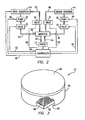
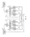
- the apparatus 10 is operated by a commercially available controller 56 as schematically depicted in the block diagrams of Figs. 2 and 6 .
- a commercially available controller 56 as schematically depicted in the block diagrams of Figs. 2 and 6 .
- oil or other fluid within the first reservoir 24 is brought up to a temperature in the range of 283°C to 320°C by activating heating elements (not shown) therein.
- the controller 56 is operative to activate the heating elements via a signal input through lead 88, or they may be independently activated by a switch (not shown) located at the first reservoir 24.
- the controller 56 then inputs signals through leads 90 and 92 to start the pump 30 and open valve 32, respectively, thus initiating the flow of heated oil out of the first reservoir 24.
- the controller 56 deactivates the pump 30 and valve 32 in line 46 from second reservoir 44 by signals input through leads 94 and 96, respectively.
- the heated oil flows to the press 12 through the manifold 28 and into the input line 34 leading into the interior of the press 12.
- the temperature of the heated oil within the press 12 is controlled and maintained by continuously recirculating it from the first reservoir 24 through the manifold 28 and input line 34 into the press 12, and then out of the press 12 through the output line 38 and manifold 28 to the recirculation line 42 connecting the manifold 28 to the first reservoir 24.
- the controller 56 opens the valve 32 within the recirculation line 42 via a signal through the line 98 to allow heated oil to pass from the manifold 28 into the first reservoir 24.
- the encapsulation process can proceed.
- the flex circuit 16 is positioned on the support 22 so that the circuit elements 54 on the LCP substrate 52 are exposed.
- a thermal insulating compound 99 such as Aerogel or a silica based material is placed over the top of each temperature sensitive circuit element 54. See Fig. 1A .
- the compound 99 is effective to assist in preventing thermal damage to the upper portion of such circuit elements during the encapsulation operation.
- the LCP cover layer 18 is then placed atop the substrate 52 and circuit elements 54.
- the controller 56 operates the pistons 50 causing the press 12 to move toward the support 22.
- the flexible plate 16 Upon engagement of the flexible membrane 16 at the bottom of the press 12 with the cover layer 18, at a uniform pressure up to 200 psi, the flexible plate 16 substantially conforms to the shape of the circuit elements 54 beneath. In turn, the cover layer 18 is forced around the circuit elements 54 into contact with substrate 52. The press 12 is maintained in this position for a period of time sufficient to heat both the LCP cover layer 18 and LCP substrate 52 to a melt temperature of at least 283°C, but not more than about 320°C, causing them to bond to one another and thus encapsulate the circuit elements 54 between the two.
- the temperature of the press 12 may be stepped down by circulating comparatively cool, ambient temperature oil into the press 12 from the second reservoir 44.
- the controller 56 is operative to deactivate the pump 30 and close valve 32 within line 26 connected to the first reservoir 24, while activating pump 30 and opening valve 32 within the line 46 connected to the second reservoir 44.
- the controller 56 closes the valve 32 within the recirculation line 42, and then opens the valve 32 within the recirculation line 48 extending from the manifold 28 to the second reservoir 44 by inputting a signal to such valve 32 through a line 100.
- ambient temperature oil is recirculated within the press 12 to reduce its temperature.
- a thermal insulating compound 99 is placed on the top surface of the temperature sensitive circuit elements 54 prior to the encapsulation operation to aid in the protection of them from the heat of the press 12.
- the support 22 provides such localized heating and cooling as follows.
- a single conduit 66 including pipes 68 and 70 is shown. It should be understood that the following discussion describing the manner in which cold fluid or hot fluid is supplied to conduit 66 applies equally to all of the other conduits 66 mounted within the support 22.
- One of the 3-way valves 84 is connected to the inlet of pipe 70 of conduit 66 by a line 102, and one of the 3-way valves 86 is connected to the inlet of pipe 68 of conduit 66 by a line 104.
- the 3-way valve 84 is also connected to the hot fluid source 78 through a line 106, and the 3-way valve 86 is connected to the cold fluid source 72 by a line 108.
- the controller 56 In order to circulate cold fluid through the conduit 66, and into contact with the underside of the top plate 60 immediately above the conduit 66, the controller 56 inputs a signal through line 110 to activate the pump 74 so that it begins pumping cold fluid from the source 72 into the distribution manifold 76.
- the operation of pump 80 is governed by the controller 56 via signals input through line 112, as described below in connection with a discussion of Fig. 5 .
- the cold fluid passes from the pump 74 into the distribution manifold 76 and then to the inlet of each of the 3-way valves 84.
- the three valves 84 and three valves 86 shown in Fig. 6 are for purposes of illustration, and there could be essentially any number of valves 84, 86 depending on how many conduits 66 are employed in the support 22.
- each individual conduit 66 is dependent on the operation of a valve pair, i.e. one of the 3-way valves 84 and one of the 3-way valves 86.
- a valve pair i.e. one of the 3-way valves 84 and one of the 3-way valves 86.
- a signal is input to 3-way valve 84 though a line 114 which opens a path through 3-way valve 84 to the line 102 connected to the inlet of pipe 70, but closes the flow path to line 106 which connects such valve 84 to the hot fluid source 78.
- the controller 56 inputs a signal through line 116 to the 3-way valve 86 connected to the pipe 68 associated with that conduit 66.
- the 3-way valve 86 is operated to permit the flow of fluid from pipe 68 into the line 108 connecting 3-way valve 86 to the cold fluid source 72, while closing the flow path through 3-way valve 86 from the distribution manifold 82.
- cold fluid from the source 72 is pumped via pump 74 through the distribution manifold 76, to the 3-way valve 84, and then into the pipe 70 of conduit 66 via line 102.
- the cold fluid is directed by pipe 70 into the channel 64 formed on the underside of the top plate 60 where it contacts and reduces the temperature of a discrete area of the top plate 60 beneath one or more temperature sensitive circuit elements 54. See also Fig. 7 .
- the cooling fluid passes through the channel 64 and enters the pipe 68 of conduit 66 from which it is discharged into the line 104 leading to the 3-way valve 86.
- the 3-way valve 86 passes the cold fluid into line 108 where it is transmitted back to the cold fluid source 72.
- the cold fluid is continuously recirculated along the above-described flow path, as depicted by arrows 118 in Fig. 4 , throughout the encapsulation process to assist in protection of the temperature sensitive circuit elements 54 from thermal damage.
- Fig. 4 The same valve arrangement described in Fig. 4 is employed to deliver hot fluid to each individual conduit 66.
- the controller 56 inputs a signal though line 112 to start the pump 80 connected to the hot fluid source 78.
- the hot fluid passes through the distribution manifold 82 to the inlet of each 3-way valve 86.
- the controller 56 inputs a signal through line 116 causing selected 3-way valves 86 to accept the flow of hot fluid from the distribution manifold 82 while closing the flow path from valve(s) 86 into line 108.
- the hot fluid passes through the 3-way valve 86 into line 104 which connects to the inlet of pipe 68 of conduit 66.
- the controller 56 operates selected 3-way valves 84 to open a flow path through such valve(s) 84 from the line 102 connected to the pipe 70 of conduit 66 into line 106 extending between the valve(s) 84 and hot fluid source 78.
- the inlet of 3-way valve 84 connected to the distribution manifold 76 is closed.
- hot fluid from the source 78 and distribution manifold 82 passes through the 3-way valve 86 into the pipe 68 of conduit 66 via line 104, and moves along a channel 64 at the underside of top plate 60 thus locally heating the top plate 60 in that immediate area.
- the hot fluid enters the pipe 70 of conduit 66 from the channel 64 and is transmitted to the line 102.
- the hot fluid is returned to the source 78 through the line 106.
- the hot fluid is preferably continuously recirculated in the direction of arrows 120 in Fig. 5 throughout the encapsulation process.
- the support 22 of this invention therefore provides localized heating and cooling of those areas of its top plate 60 where enhanced heat for encapsulation, or additional cooling to protect temperature sensitive circuit elements 54, is desired.
- localized heating or cooling can be provided by each individual conduit 66 or groups of conduits 66, as needed. This allows for the efficient encapsulation of LCP circuits 20 of essentially any configuration, one after the other.
- the flow of hot or cold fluid through any given conduit 66 can be readily reversed by the controller 56, thus permitting the temperature of the area of the top plate 60 immediately above to be rapidly cooled if it was previously heated, or vice versa.
Abstract
Description
- This invention is directed to flexible circuits, and, more particularly, to an apparatus for sealing circuit elements of a flexible circuit, including heat sensitive circuit elements, which are mounted on a substrate formed of liquid crystal polymer to protect them from exposure to moisture and contaminants.
- Flexible or "flex" circuits are used in a wide variety of applications where an electrical circuit must bend around corners or be flexed during operation. Flex circuits are thin, light weight, flexible and exhibit high routability. Traditionally, polyimide films have been used as substrates in the manufacture of flex circuits due to their good thermal stability and mechanical strength. Other properties of polyimide films, however, limit the speed or frequency at which electric components mounted thereto can operate.
- Liquid crystal polymer ("LCP") has been developed in recent years as a replacement for polyimide films in flex circuits. LCP is a thermoplastic aromatic polyester which is thermally stable, with an upper use temperature in excess of 250°C and good inherent flame retardant properties. LCP films, in comparison to polyimide films, have about one-tenth of the moisture uptake and a lower coefficient of humidity expansion. Lower moisture absorption leads to higher frequency signal and data processing stability. Additionally, LCP films have a lower dielectric constant and a lower loss or dissipation factor over the functional frequency range of 1kHz to 45 GHz, with negligible moisture effects, compared to polyimide films.
- The fabrication of flex circuits with LCP films is expected to lead to their use in more demanding environments where moisture and other contaminants are prevalent. Particularly in such types of applications, the circuit elements applied to the LCP substrate of the flex circuit must be protected from damage. Soldermask coatings, which have been employed to provide protection from moisture and contaminants in polyimide films, have been considered for use with LCP substrates. Additionally, due to the thermoplastic nature of LCP, the application of an LCP film cover layer to an LCP substrate has been proposed as a means of encapsulating circuit elements. With respect to LCP cover layers, current practice is to employ an air knife or laser to create localized heating of the LCP cover layer and LCP substrate along the periphery of the flex circuit. A number of problems can arise from this approach. A failure of the seal between the cover layer and substrate at any point along the periphery of the flex circuit can expose all of the circuit elements to moisture, chemicals or other contaminants. If the air between the cover layer and substrate is not fully removed, pressurization of the flex circuit which would occur in underwater applications, for example, could compress such air and create a bubble potentially resulting in a rupture of the cover layer and/or substrate thus creating a failure of the entire circuit.
- The melt temperature of LCP material is approximately 283°C, and soldermask coatings are also applied at relatively high temperatures. While a number of standard circuit elements are not affected by high temperatures, components such as micro-electrical-mechanical-system ("MEMS") sensors, infra-red sensors and a variety of other circuit elements are temperature sensitive and can be damaged or destroyed upon exposure to elevated temperatures. There is a need for an efficient and dependable method and apparatus capable of individually sealing or encapsulating the electrical components of circuits which employ an LCP substrate, while protecting heat sensitive components of the circuit from damage due to the temperatures at which the sealing process is performed.
-
DE 199 20 577 discloses a pressing apparatus for coating a piece through a membrane press. Such an apparatus comprises: a container for warm liquid and a container for cold liquid; a press with two membranes and for forming two different chambers; a support carrying a piece covered with covering material; conduits between the containers and the first chamber. In a first operation step, the warm liquid flows into the first chamber so as the high temperature causes the piece to be coated by the material. In a second operation step, the warm liquid is sucked from the first chamber; the cold liquid flows into the first chamber. The second chamber is configured for containing compressed air in different operation steps. - This invention is directed to an apparatus for affixing an LCP cover layer to a flex circuit consisting of circuit elements mounted to an LCP substrate, at least some of which are temperature sensitive, in order to individually protect the circuit elements from damage and/or reduced operational efficiency due to the presence of moisture, chemical and other contaminants.
- In the presently preferred embodiment, the apparatus includes an iso-static press having a hollow interior connected to a source of oil or other liquid whose temperature can be accurately controlled and maintained. The oil is heated to a temperature in the range of approximately 283°C to 320°C and transferred from a reservoir into the interior of the press. The base of the press has a plate or membrane formed of a flexible material covered with a non-stick surface which does not adhere to LCP.
- The flex circuit is placed on the surface of the thermally conductive top plate of a support such that the circuit elements are exposed. A thermal insulating compound may be placed over each temperature sensitive circuit element for added thermal protection. The support includes a housing formed with a cavity within which a number of conduits are mounted each having an upper end communicating with a channel formed in the underside of the top plate. Cooling fluid from a source is circulated through selected conduits, i.e. those which are located beneath the temperature sensitive circuit elements of the flex circuit, to provide localized cooling of such elements during the lamination process. Other conduits, which are not located near the temperature sensitive circuit elements, may be supplied with a heating fluid to raise the temperature of the top plate of the support in selected areas and thus assist with the lamination process.
- With the flex circuit in place on the top plate of the support, and the conduits within the support receiving cooling fluid or heating fluid to cool or heat selected areas of the top plate, an LCP cover layer is placed atop the flex circuit and the press is activated to move into contact with the cover layer. The flexible membrane at the base of the press is capable of substantially conforming to the shape of the circuit elements, thus urging the LCP cover layer around each of them individually to the underlying LCP substrate of the flex circuit. The temperature and pressure applied by the press, and the elevated temperature of selected areas of the support top plate, are sufficient to cause the LCP cover layer and substrate to "relax" or melt to a limited extent and thus adhere together forming a secure bond so that the circuit elements are individually encapsulated between the two layers.
- The structure, operation and advantages of the presently preferred embodiment of this invention will become further apparent upon consideration of the following description, taken in conjunction with the accompanying drawings, wherein:
-
FIG. 1 is a schematic, perspective view of the apparatus of this invention; -
FIG. 2 is a block diagram illustrating the operation of the press of the apparatus shown inFig. 1 ; -
FIG. 3 is a perspective view of the support for the flex circuit with a portion cut away to show the conduits mounted within a cavity in the support; -
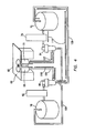
FIG. 4 is a schematic view of one conduit of the support connected by 3-way valves to a hot fluid source and a cold fluid source, wherein cooling fluid is being supplied to the conduit; -
FIG. 1A is an enlarged view of the encircled portion ofFig. 1 ; -
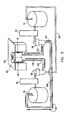
FIG. 5 is a view similar toFig. 4 , except with hot fluid being supplied to the conduit; -
FIG. 6 is a schematic, block diagram depicting the structure for supplying hot fluid and cooling fluid to the conduit; and -
FIG. 7 is a cross sectional view of the connection between a conduit and the top plate of the support. - Referring now to the Figs., the
apparatus 10 of this invention is schematically illustrated. Theapparatus 10 includes an iso-static press 12 having ahousing 14 formed with a hollow interior. The base of thehousing 14 mounts aflexible membrane 16 having an exposed surface coated with Teflon® or other release agent which will not stick to LCP, and an inside surface coated with a hydrophobic film. Preferably, theflexible membrane 16 is formed of high density polyethylene, butyl rubber, ethylene propylene diene monomer rubber or a similar material. - The
press 12 is operative to apply heat and pressure against acover layer 18 which overlies aflex circuit 20 placed upon asupport 22. In the presently preferred embodiment, thepress 12 is heated by the introduction into its hollow interior of heated oil or a similar fluid whose temperature can be relatively accurately controlled and maintained within the range of about 283°C to 320°C. Afirst reservoir 24 having heating elements (not shown) is connected by asupply line 26 to amanifold 28. Apump 30 andvalve 32 are located in thesupply line 26, between thefirst reservoir 24 andmanifold 28, as shown. Themanifold 28, in turn, is connected by aninput line 34 to one port at the top of thepress 12, and by anoutput line 38 to a second port. Arecirculation line 42, containing avalve 32, is connected between themanifold 28 and the top of thefirst reservoir 24. - In view of the relatively high temperature obtained by the
press 12 during operation, it is advantageous to provide a cooling capability to step the temperature down. To that end, asecond reservoir 44 is provided which contains the same fluid asfirst reservoir 24 except at ambient temperature. The bottom ofsecond reservoir 44 is connected by aline 46 to themanifold 28, and arecirculation line 48 connects themanifold 28 to the top of thesecond reservoir 44. Apump 30 andvalve 32 are located in theline 46 between thesecond reservoir 44 andmanifold 28, and avalve 32 is mounted in therecirculation line 48. - The
press 12 is moved with respect to thesupport 22 by a number of pneumatic orhydraulic pistons 50 which are mounted at equal intervals along the top surface of thepress 12. Conventionally, thepistons 50 are independently actuated by a source of air or fluid (not shown) to ensure that thepress 12 applies uniform pressure to thecover layer 18 andflex circuit 20 over the entire surface area of theflexible membrane 16. The detailed construction of thepress 12 forms no part of this invention, and is therefore not discussed further herein. - As discussed above, the method and
apparatus 10 of this invention are designed to provide a means for individually encapsulating circuit elements to protect them from moisture and contaminants. Theflex circuit 20 consists of asubstrate 52 formed of LCP - upon which a number ofcircuit elements 54 are mounted. Thecover layer 18 is also formed of LCP, which, because of its thermoplastic nature, will "relax" or begin to melt at a temperature of about 283°C. By placing thecover layer 18 over theflex circuit 20 and applying heat and pressure, thecover layer 18 andsubstrate 52 adhere to one another with a secure bond and entirely enclose thecircuit elements 54 between them. - At least some of the
circuit elements 54 are temperature sensitive and would be damaged by exposure to heat on the order of the melt temperature of the LCP layers. Thesupport 22 is constructed to provide localized cooling of the temperaturesensitive circuit elements 54, and to generate heat in other areas of thesubstrate 52 which raises its temperature to assist with the lamination or encapsulation process. With reference now toFigs. 3-7 , thesupport 22 includes aside wall 56 defining aninternal cavity 58 which is closed by atop plate 60 and abottom plate 62. Thetop plate 60 is preferably formed of a highly thermally conductive material such as aluminum silica carbide. A number ofchannels 64 are machined or otherwise formed in the underside of thetop plate 60, each of which mounts aconduit 66. SeeFig. 7 . Theconduits 66 are depicted in the Figs. as a pair of side-by-side pipes channel 64 in thetop plate 60 so that fluid can pass between the two. It should be understood, however, that theconduit 66 may be a unitary structure formed with an internal wall so as to define two separate flow paths, for purposes to become apparent below. - An array of
conduits 66 is carried within thecavity 58 of thesupport 22 atop thebottom plate 62 and extending beneath substantially the entire surface area of thetop plate 60. Structure is provided to transmit either cold fluid or hot fluid into eachconduit 66, depending on the position of the temperaturesensitive circuit elements 54 resting on thetop plate 60 of thesupport 22, so that such fluid produces localized heating or cooling of thetop plate 60. As best seen inFigs. 4-6 , this structure includes a coldfluid source 72 connected to apump 74, which, in turn, is connected to adistribution manifold 76 and, a hotfluid source 78 connected by apump 80 to asecond distribution manifold 82. While the "hot"fluid source 78 is shown as a separate reservoir in the Figs., it is contemplated that thefirst reservoir 24 supplying heated fluid to thepress 12 may be employed to transmit hot fluid to theconduits 66, if desired. - As described more fully below in connection with a discussion of the operation of the
apparatus 10 of this invention, thedistribution manifold 76 connected to the coldfluid source 72 transmits such fluid to number of 3-way valves 84. Each 3-way valve 84, in turn, is connected to the inlet of thepipe 70 of aconduit 66. Similarly, thedistribution manifold 82 receiving hot fluid fromsource 78 is connected to a number of 3-way valves 86, each of which connects to the inlet of apipe 68 of aconduit 66. Consequently, depending upon the operative position of the 3-way valves conduit 66 to obtain localized heating or cooling of thetop plate 60 in the area located immediately abovesuch conduit 66. - The operation of the
press 12 of this invention is described initially below, followed by a discussion of the localized cooling and heating provided by thesupport 22. - The
apparatus 10 is operated by a commerciallyavailable controller 56 as schematically depicted in the block diagrams ofFigs. 2 and6 . Initially, oil or other fluid within thefirst reservoir 24 is brought up to a temperature in the range of 283°C to 320°C by activating heating elements (not shown) therein. Thecontroller 56 is operative to activate the heating elements via a signal input throughlead 88, or they may be independently activated by a switch (not shown) located at thefirst reservoir 24. Thecontroller 56 then inputs signals throughleads pump 30 andopen valve 32, respectively, thus initiating the flow of heated oil out of thefirst reservoir 24. When it is desired to heat thepress 12 in preparation for circuit encapsulation, thecontroller 56 deactivates thepump 30 andvalve 32 inline 46 fromsecond reservoir 44 by signals input throughleads press 12 through the manifold 28 and into theinput line 34 leading into the interior of thepress 12. Preferably, the temperature of the heated oil within thepress 12 is controlled and maintained by continuously recirculating it from thefirst reservoir 24 through the manifold 28 andinput line 34 into thepress 12, and then out of thepress 12 through theoutput line 38 andmanifold 28 to therecirculation line 42 connecting the manifold 28 to thefirst reservoir 24. Thecontroller 56 opens thevalve 32 within therecirculation line 42 via a signal through theline 98 to allow heated oil to pass from the manifold 28 into thefirst reservoir 24. - With the
press 12 at the appropriate temperature, the encapsulation process can proceed. Theflex circuit 16 is positioned on thesupport 22 so that thecircuit elements 54 on theLCP substrate 52 are exposed. In the presently preferred embodiment, a thermal insulatingcompound 99 such as Aerogel or a silica based material is placed over the top of each temperaturesensitive circuit element 54. SeeFig. 1A . Thecompound 99 is effective to assist in preventing thermal damage to the upper portion of such circuit elements during the encapsulation operation. TheLCP cover layer 18 is then placed atop thesubstrate 52 andcircuit elements 54. Thecontroller 56 operates thepistons 50 causing thepress 12 to move toward thesupport 22. Upon engagement of theflexible membrane 16 at the bottom of thepress 12 with thecover layer 18, at a uniform pressure up to 200 psi, theflexible plate 16 substantially conforms to the shape of thecircuit elements 54 beneath. In turn, thecover layer 18 is forced around thecircuit elements 54 into contact withsubstrate 52. Thepress 12 is maintained in this position for a period of time sufficient to heat both theLCP cover layer 18 andLCP substrate 52 to a melt temperature of at least 283°C, but not more than about 320°C, causing them to bond to one another and thus encapsulate thecircuit elements 54 between the two. - After completing one or more encapsulation procedures, the temperature of the
press 12 may be stepped down by circulating comparatively cool, ambient temperature oil into thepress 12 from thesecond reservoir 44. Thecontroller 56 is operative to deactivate thepump 30 andclose valve 32 withinline 26 connected to thefirst reservoir 24, while activatingpump 30 andopening valve 32 within theline 46 connected to thesecond reservoir 44. Thecontroller 56 closes thevalve 32 within therecirculation line 42, and then opens thevalve 32 within therecirculation line 48 extending from the manifold 28 to thesecond reservoir 44 by inputting a signal tosuch valve 32 through aline 100. As a result, ambient temperature oil is recirculated within thepress 12 to reduce its temperature. - As noted above, a thermal insulating
compound 99 is placed on the top surface of the temperaturesensitive circuit elements 54 prior to the encapsulation operation to aid in the protection of them from the heat of thepress 12. For additional thermal protection, it is desirable to provide localized cooling of thetop plate 60 ofsupport 22 in those areas located immediately beneath thecircuit elements 54. Additionally, the encapsulation process may be enhanced by heating areas of thetop plate 60 which are spaced from the thermallysensitive circuit elements 54. Thesupport 22 provides such localized heating and cooling as follows. - For purposes of the present discussion, and with reference initially to
Figs. 4 and6 , asingle conduit 66 includingpipes conduit 66 applies equally to all of theother conduits 66 mounted within thesupport 22. One of the 3-way valves 84 is connected to the inlet ofpipe 70 ofconduit 66 by aline 102, and one of the 3-way valves 86 is connected to the inlet ofpipe 68 ofconduit 66 by aline 104. The 3-way valve 84 is also connected to the hotfluid source 78 through aline 106, and the 3-way valve 86 is connected to the coldfluid source 72 by aline 108. In order to circulate cold fluid through theconduit 66, and into contact with the underside of thetop plate 60 immediately above theconduit 66, thecontroller 56 inputs a signal throughline 110 to activate thepump 74 so that it begins pumping cold fluid from thesource 72 into thedistribution manifold 76. The operation ofpump 80 is governed by thecontroller 56 via signals input throughline 112, as described below in connection with a discussion ofFig. 5 . The cold fluid passes from thepump 74 into thedistribution manifold 76 and then to the inlet of each of the 3-way valves 84. It should be understood that the threevalves 84 and threevalves 86 shown inFig. 6 are for purposes of illustration, and there could be essentially any number ofvalves many conduits 66 are employed in thesupport 22. - As best seen in
Fig. 4 , flow of cold fluid or heated fluid into eachindividual conduit 66 is dependent on the operation of a valve pair, i.e. one of the 3-way valves 84 and one of the 3-way valves 86. Once the position of the thermallysensitive circuit elements 54 on thetop plate 60 ofsupport 22 is determined, the group(s) ofconduits 66, orindividual conduits 66, which are located immediately beneath such areas are identified. Thecontroller 56 is operative to introduce cold fluid into such conduit(s) 66 as follows. A signal is input to 3-way valve 84 though aline 114 which opens a path through 3-way valve 84 to theline 102 connected to the inlet ofpipe 70, but closes the flow path to line 106 which connectssuch valve 84 to the hotfluid source 78. At the same time, thecontroller 56 inputs a signal throughline 116 to the 3-way valve 86 connected to thepipe 68 associated with thatconduit 66. The 3-way valve 86 is operated to permit the flow of fluid frompipe 68 into theline 108 connecting 3-way valve 86 to the coldfluid source 72, while closing the flow path through 3-way valve 86 from thedistribution manifold 82. Consequently, cold fluid from thesource 72 is pumped viapump 74 through thedistribution manifold 76, to the 3-way valve 84, and then into thepipe 70 ofconduit 66 vialine 102. The cold fluid is directed bypipe 70 into thechannel 64 formed on the underside of thetop plate 60 where it contacts and reduces the temperature of a discrete area of thetop plate 60 beneath one or more temperaturesensitive circuit elements 54. See alsoFig. 7 . The cooling fluid passes through thechannel 64 and enters thepipe 68 ofconduit 66 from which it is discharged into theline 104 leading to the 3-way valve 86. The 3-way valve 86 passes the cold fluid intoline 108 where it is transmitted back to the coldfluid source 72. The cold fluid is continuously recirculated along the above-described flow path, as depicted byarrows 118 inFig. 4 , throughout the encapsulation process to assist in protection of the temperaturesensitive circuit elements 54 from thermal damage. - Other areas of the
flex circuit 20mount circuit elements 54 which are not affected by the temperature of the encapsulation process. In these areas, it is desirable to locally heat thetop plate 60 of thesupport 22 to assist thepress 12 with the encapsulation process. The same valve arrangement described inFig. 4 is employed to deliver hot fluid to eachindividual conduit 66. With reference toFigs. 5 and6 , in order to obtain a flow of hot fluid into theconduit 66 thecontroller 56 inputs a signal thoughline 112 to start thepump 80 connected to the hotfluid source 78. The hot fluid passes through thedistribution manifold 82 to the inlet of each 3-way valve 86. Thecontroller 56 inputs a signal throughline 116 causing selected 3-way valves 86 to accept the flow of hot fluid from thedistribution manifold 82 while closing the flow path from valve(s) 86 intoline 108. The hot fluid passes through the 3-way valve 86 intoline 104 which connects to the inlet ofpipe 68 ofconduit 66. At the same time, thecontroller 56 operates selected 3-way valves 84 to open a flow path through such valve(s) 84 from theline 102 connected to thepipe 70 ofconduit 66 intoline 106 extending between the valve(s) 84 and hotfluid source 78. The inlet of 3-way valve 84 connected to thedistribution manifold 76 is closed. As a result, hot fluid from thesource 78 anddistribution manifold 82 passes through the 3-way valve 86 into thepipe 68 ofconduit 66 vialine 104, and moves along achannel 64 at the underside oftop plate 60 thus locally heating thetop plate 60 in that immediate area. The hot fluid enters thepipe 70 ofconduit 66 from thechannel 64 and is transmitted to theline 102. After passing through the 3-way valve 84, the hot fluid is returned to thesource 78 through theline 106. The hot fluid is preferably continuously recirculated in the direction ofarrows 120 inFig. 5 throughout the encapsulation process. - The
support 22 of this invention therefore provides localized heating and cooling of those areas of itstop plate 60 where enhanced heat for encapsulation, or additional cooling to protect temperaturesensitive circuit elements 54, is desired. Depending upon how thevalve pair conduit 66 is operated, as described above, localized heating or cooling can be provided by eachindividual conduit 66 or groups ofconduits 66, as needed. This allows for the efficient encapsulation ofLCP circuits 20 of essentially any configuration, one after the other. The flow of hot or cold fluid through any givenconduit 66 can be readily reversed by thecontroller 56, thus permitting the temperature of the area of thetop plate 60 immediately above to be rapidly cooled if it was previously heated, or vice versa.
Claims (8)
- Apparatus for sealing circuit elements of an electrical circuit between a substrate (52) upon which the circuit elements (54) are mounted and a cover layer (18), said apparatus comprising:a press (12) having a hollow interior, said press (12) being adapted to be connected to a source of heated fluid;a support (22) configured to carry the substrate (52) and the cover layer (18), at least some of the circuit elements (54) on the substrate (52) being temperature sensitive,characterized in that said support (22) includes:(i) a housing formed with a cavity (58);(ii) a number of conduits (66) mounted in said cavity (58), each of the conduits (66) having a hollow interior adapted to receive cooling fluid from a source of cooling fluid (72);a controller (56) which is effective to direct cooling fluid into those of said conduits (66) which are located in position underlying the temperature sensitive circuit elements (54) carried on the substrate (52);whereby said press (12) when at least partially filled with heating fluid moves into contact with the cover layer (18) overlying the substrate (52) and exerts sufficient heat and pressure to cause the cover layer (18) and substrate (52) to bond together while the heat sensitive circuit elements (54) are cooled by said conduits (66) receiving cooling fluid.
- The apparatus of claim 1 in which said press (12) is an iso-static press capable of exerting substantially equal pressure over the surface area of the cover layer (18) and substrate.
- The apparatus of claim 1 in which said press (12) includes a flexible membrane (16) engageable with the cover layer (18), said flexible membrane (16) substantially conforming to the shape of the circuit elements (54) on the substrate (52) in the course of movement into engagement with the cover layer (18).
- The apparatus of claim 1 further including thermal insulating compound (99) located in between the temperature sensitive circuit elements (54) and the cover layer (18).
- The apparatus of claim 1 in which each of said conduits (66) mounted in said cavity (58) of said housing of said support (22) includes a first flow path communicating with a second flow path, one of said first and second flow paths forming an inlet adapted to receive cooling fluid from said source of cooling fluid (72) and the other of said first and second flow paths forming an outlet adapted to return cooling fluid to said source of cooling fluid (72), the cooling fluid contacting and lowering the temperature of a discrete area of said support (22) in the course of movement along said first and second flow paths.
- The apparatus of claim 5 in which said conduit (66) includes a first pipe (68) having a hollow interior defining said first flow path and a second pipe (70) having a hollow interior defining said second flow path, said support (22) having a top plate formed with a channel (64) connected to an upper end of each of said first and second pipes (68, 70), said channel (64) interconnecting said hollow interiors of said first and second pipes (68, 70).
- The apparatus of claim 1 in which said conduits (66) are adapted, to connect to said source of heated fluid, said controller (56) being effective to direct heated fluid into those of said conduits (66) which are spaced from the temperature sensitive circuit elements (54) on the substrate (52).
- The apparatus of claim 1 in which each of the substrate (52) and the cover layer (18) are formed of liquid crystal polymer.
Applications Claiming Priority (2)
| Application Number | Priority Date | Filing Date | Title |
|---|---|---|---|
| US11/050,303 US7128801B2 (en) | 2005-02-03 | 2005-02-03 | Method and apparatus for sealing flex circuits having heat sensitive circuit elements |
| PCT/US2006/003245 WO2006083773A2 (en) | 2005-02-03 | 2006-01-31 | Method and apparatus for sealing flex circuits having heat sensitive circuit elements |
Publications (3)
| Publication Number | Publication Date |
|---|---|
| EP1848578A2 EP1848578A2 (en) | 2007-10-31 |
| EP1848578A4 EP1848578A4 (en) | 2010-09-22 |
| EP1848578B1 true EP1848578B1 (en) | 2011-09-07 |
Family
ID=36755257
Family Applications (1)
| Application Number | Title | Priority Date | Filing Date |
|---|---|---|---|
| EP06719889A Active EP1848578B1 (en) | 2005-02-03 | 2006-01-31 | Apparatus for sealing flex circuits having heat sensitive circuit elements |
Country Status (7)
| Country | Link |
|---|---|
| US (2) | US7128801B2 (en) |
| EP (1) | EP1848578B1 (en) |
| JP (1) | JP4607194B2 (en) |
| KR (1) | KR100902436B1 (en) |
| CN (1) | CN101146665B (en) |
| CA (1) | CA2596440C (en) |
| WO (1) | WO2006083773A2 (en) |
Families Citing this family (12)
| Publication number | Priority date | Publication date | Assignee | Title |
|---|---|---|---|---|
| EP1972289B1 (en) | 2007-03-23 | 2018-10-17 | coLigne AG | Elongated stabilization member and bone anchor useful in bone and especially spinal repair processes |
| US20090011192A1 (en) * | 2007-07-03 | 2009-01-08 | John Tomczyk | Method, system, and apparatus for producing dimensional image articles utilizing a cushioning assembly |
| US8014167B2 (en) * | 2007-09-07 | 2011-09-06 | Seagate Technology Llc | Liquid crystal material sealed housing |
| US20090105532A1 (en) * | 2007-10-22 | 2009-04-23 | Zvika Gilad | In vivo imaging device and method of manufacturing thereof |
| US20090188105A1 (en) * | 2008-01-28 | 2009-07-30 | Ming-Chin Chien | Slim battery packaging method |
| US8231692B2 (en) * | 2008-11-06 | 2012-07-31 | International Business Machines Corporation | Method for manufacturing an electronic device |
| US8279552B2 (en) * | 2010-06-22 | 2012-10-02 | Hitachi Global Storage Technologies, Netherlands B.V. | Hermetically sealing a hard disk drive |
| EP2540500B1 (en) | 2011-06-28 | 2016-10-26 | Actilor Intellectual Asset AG | Lamination device and method for films with temperature-sensitive elements and documents produced with same |
| JP6492049B2 (en) | 2013-03-12 | 2019-03-27 | カーディアック ペースメイカーズ, インコーポレイテッド | Implantable medical device and assembly thereof |
| US10379134B2 (en) * | 2013-08-29 | 2019-08-13 | Jaquet Technology Group Ag | Sensor device for determining rotational speed of a rotatable object and turbocharger with such a sensor device |
| US9282650B2 (en) * | 2013-12-18 | 2016-03-08 | Intel Corporation | Thermal compression bonding process cooling manifold |
| US10192847B2 (en) * | 2014-06-12 | 2019-01-29 | Asm Technology Singapore Pte Ltd | Rapid cooling system for a bond head heater |
Family Cites Families (22)
| Publication number | Priority date | Publication date | Assignee | Title |
|---|---|---|---|---|
| JPS51109036A (en) * | 1975-03-20 | 1976-09-27 | Yasuo Saito | OTOTSUMENNOPURESUSETSUCHAKUSOCHI |
| DE3611839A1 (en) * | 1986-04-09 | 1987-10-15 | Siempelkamp Gmbh & Co | METHOD FOR PRODUCING A PRESS PLATE HEATABLE BY A FLUID MEDIUM |
| JP2787581B2 (en) * | 1988-10-31 | 1998-08-20 | 株式会社小松製作所 | Temperature control device for plastic compression molding machine |
| JP3230833B2 (en) * | 1992-03-27 | 2001-11-19 | 日立テクノエンジニアリング株式会社 | hot press |
| AU4531793A (en) | 1992-06-12 | 1994-01-04 | Aluminum Company Of America | Method of fabricating multilayer structures with nonplanar surfaces |
| JPH07195391A (en) * | 1993-12-28 | 1995-08-01 | Hitachi Techno Eng Co Ltd | Hot press |
| JPH07242085A (en) * | 1994-03-01 | 1995-09-19 | Mitsubishi Electric Corp | Ic card and manufacture of ic card |
| US5827999A (en) * | 1994-05-26 | 1998-10-27 | Amkor Electronics, Inc. | Homogeneous chip carrier package |
| US20020079053A1 (en) * | 1994-09-21 | 2002-06-27 | Yamauchi Corporation | Cushioning material for forming press |
| US6320257B1 (en) * | 1994-09-27 | 2001-11-20 | Foster-Miller, Inc. | Chip packaging technique |
| US5993593A (en) * | 1996-12-03 | 1999-11-30 | Heat Sealing Technology, Inc. | High-temperature, heat-sealed products and methods and means for their manufacture |
| US6110321A (en) * | 1997-02-28 | 2000-08-29 | General Electric Company | Method for sealing an ultracapacitor, and related articles |
| JP3098003B2 (en) * | 1998-09-24 | 2000-10-10 | 日清紡績株式会社 | Laminating equipment for solar cells |
| JP2000117493A (en) * | 1998-10-15 | 2000-04-25 | Kitagawa Elaborate Mach Co Ltd | Surface plate cooling system in hot pressing device |
| JP4138995B2 (en) * | 1999-03-31 | 2008-08-27 | 株式会社クラレ | Circuit board and manufacturing method thereof |
| DE19920577C1 (en) * | 1999-05-04 | 2001-01-04 | Wemhoener Heinrich Gmbh Co | Membrane press for multi-sided laminating of furniture plates etc has two supply containers for two different temperature fluids and with operating valves opened and closed by press control mechanism |
| AU2002227246A1 (en) | 2000-12-14 | 2002-06-24 | World Properties Inc. | Liquid crystalline polymer bond plies and circuits formed therefrom |
| JP2002217523A (en) * | 2001-01-23 | 2002-08-02 | Tdk Corp | Method of manufacturing electronic device |
| JP4513235B2 (en) * | 2001-05-31 | 2010-07-28 | ソニー株式会社 | Flip chip mounting device |
| US6675852B2 (en) * | 2001-06-15 | 2004-01-13 | International Business Machines Corporation | Platen for use in laminating press |
| US6977187B2 (en) | 2002-06-19 | 2005-12-20 | Foster-Miller, Inc. | Chip package sealing method |
| US7768619B2 (en) * | 2004-08-03 | 2010-08-03 | Harris Corporation | Method and apparatus for sealing flex circuits made with an LCP substrate |
-
2005
- 2005-02-03 US US11/050,303 patent/US7128801B2/en active Active
-
2006
- 2006-01-31 JP JP2007554152A patent/JP4607194B2/en not_active Expired - Fee Related
- 2006-01-31 WO PCT/US2006/003245 patent/WO2006083773A2/en active Search and Examination
- 2006-01-31 EP EP06719889A patent/EP1848578B1/en active Active
- 2006-01-31 CA CA2596440A patent/CA2596440C/en not_active Expired - Fee Related
- 2006-01-31 KR KR1020077017994A patent/KR100902436B1/en not_active IP Right Cessation
- 2006-01-31 CN CN2006800073646A patent/CN101146665B/en not_active Expired - Fee Related
- 2006-08-08 US US11/463,087 patent/US7591924B2/en active Active
Also Published As
| Publication number | Publication date |
|---|---|
| CN101146665B (en) | 2010-11-10 |
| KR100902436B1 (en) | 2009-06-11 |
| CN101146665A (en) | 2008-03-19 |
| WO2006083773A2 (en) | 2006-08-10 |
| JP2008538855A (en) | 2008-11-06 |
| US20060286189A1 (en) | 2006-12-21 |
| US7591924B2 (en) | 2009-09-22 |
| US20060169405A1 (en) | 2006-08-03 |
| EP1848578A2 (en) | 2007-10-31 |
| EP1848578A4 (en) | 2010-09-22 |
| WO2006083773A3 (en) | 2006-12-21 |
| US7128801B2 (en) | 2006-10-31 |
| KR20070092324A (en) | 2007-09-12 |
| CA2596440A1 (en) | 2009-08-10 |
| JP4607194B2 (en) | 2011-01-05 |
| CA2596440C (en) | 2010-12-14 |
Similar Documents
| Publication | Publication Date | Title |
|---|---|---|
| EP1848578B1 (en) | Apparatus for sealing flex circuits having heat sensitive circuit elements | |
| US6041840A (en) | Vacuum lamination device and a vacuum lamination method | |
| US6031212A (en) | Heating apparatus for composite structure repair | |
| JP3790724B2 (en) | Laminating apparatus and laminating method | |
| US20110109335A1 (en) | Direct liquid-contact micro-channel heat transfer devices, methods of temperature control for semiconductive devices, and processes of forming same | |
| RU2008116590A (en) | METHOD AND DEVICE FOR ADHESIVE COMPONENTS TO COMPOSITE FORMED PRODUCT | |
| JP3627090B2 (en) | Lamination molding method and lamination molding apparatus | |
| JP2008538855A5 (en) | ||
| EP1789840B1 (en) | Method and apparatus for sealing flex circuits made with an lcp substrate | |
| KR960011853B1 (en) | Method and apparatus for packaging integrated circuit chips employing a polymer film overlay layer | |
| KR20160134685A (en) | Electronic control module and method for producing the same | |
| JPH11210983A (en) | Vacuum thermal insulating panel and its manufacture | |
| JPS62275600A (en) | Vacuum hot press | |
| JP3243607B2 (en) | Vacuum laminating apparatus and vacuum laminating method | |
| JP3243598B2 (en) | Vacuum laminating apparatus and vacuum laminating method | |
| JP3243608B2 (en) | Vacuum laminating apparatus and vacuum laminating method | |
| JPS6389327A (en) | Thermocompression bonding device | |
| JP2001113549A (en) | Vacuum laminating apparatus and method | |
| JP2006286625A (en) | Fuel cell heating/molding device | |
| JP2001079865A (en) | Vacuum laminating apparatus | |
| JPH10175229A (en) | Vacuum laminating apparatus | |
| KR20030021205A (en) | Temperature-control method for air bed | |
| JPH07108553A (en) | Connection structure of vacuum chamber with flow passage piping |
Legal Events
| Date | Code | Title | Description |
|---|---|---|---|
| PUAI | Public reference made under article 153(3) epc to a published international application that has entered the european phase |
Free format text: ORIGINAL CODE: 0009012 |
|
| 17P | Request for examination filed |
Effective date: 20070828 |
|
| AK | Designated contracting states |
Kind code of ref document: A2 Designated state(s): DE FI FR GB SE |
|
| DAX | Request for extension of the european patent (deleted) | ||
| RBV | Designated contracting states (corrected) |
Designated state(s): DE FI FR GB SE |
|
| A4 | Supplementary search report drawn up and despatched |
Effective date: 20100819 |
|
| GRAP | Despatch of communication of intention to grant a patent |
Free format text: ORIGINAL CODE: EPIDOSNIGR1 |
|
| RIC1 | Information provided on ipc code assigned before grant |
Ipc: B30B 5/02 20060101ALN20110314BHEP Ipc: B29C 65/00 20060101AFI20110314BHEP Ipc: H05K 3/28 20060101ALN20110314BHEP |
|
| RTI1 | Title (correction) |
Free format text: APPARATUS FOR SEALING FLEX CIRCUITS HAVING HEAT SENSITIVE CIRCUIT ELEMENTS |
|
| GRAS | Grant fee paid |
Free format text: ORIGINAL CODE: EPIDOSNIGR3 |
|
| GRAA | (expected) grant |
Free format text: ORIGINAL CODE: 0009210 |
|
| REG | Reference to a national code |
Ref country code: GB Ref legal event code: FG4D |
|
| REG | Reference to a national code |
Ref country code: DE Ref legal event code: R096 Ref document number: 602006024194 Country of ref document: DE Effective date: 20111117 |
|
| REG | Reference to a national code |
Ref country code: SE Ref legal event code: TRGR |
|
| PGFP | Annual fee paid to national office [announced via postgrant information from national office to epo] |
Ref country code: FI Payment date: 20120127 Year of fee payment: 7 Ref country code: SE Payment date: 20120127 Year of fee payment: 7 |
|
| PLBE | No opposition filed within time limit |
Free format text: ORIGINAL CODE: 0009261 |
|
| STAA | Information on the status of an ep patent application or granted ep patent |
Free format text: STATUS: NO OPPOSITION FILED WITHIN TIME LIMIT |
|
| 26N | No opposition filed |
Effective date: 20120611 |
|
| REG | Reference to a national code |
Ref country code: DE Ref legal event code: R097 Ref document number: 602006024194 Country of ref document: DE Effective date: 20120611 |
|
| REG | Reference to a national code |
Ref country code: SE Ref legal event code: EUG |
|
| PG25 | Lapsed in a contracting state [announced via postgrant information from national office to epo] |
Ref country code: FI Free format text: LAPSE BECAUSE OF NON-PAYMENT OF DUE FEES Effective date: 20130131 Ref country code: SE Free format text: LAPSE BECAUSE OF NON-PAYMENT OF DUE FEES Effective date: 20130201 |
|
| PGFP | Annual fee paid to national office [announced via postgrant information from national office to epo] |
Ref country code: GB Payment date: 20150127 Year of fee payment: 10 |
|
| REG | Reference to a national code |
Ref country code: FR Ref legal event code: PLFP Year of fee payment: 11 |
|
| GBPC | Gb: european patent ceased through non-payment of renewal fee |
Effective date: 20160131 |
|
| PG25 | Lapsed in a contracting state [announced via postgrant information from national office to epo] |
Ref country code: GB Free format text: LAPSE BECAUSE OF NON-PAYMENT OF DUE FEES Effective date: 20160131 |
|
| REG | Reference to a national code |
Ref country code: FR Ref legal event code: PLFP Year of fee payment: 12 |
|
| REG | Reference to a national code |
Ref country code: FR Ref legal event code: PLFP Year of fee payment: 13 |
|
| PGFP | Annual fee paid to national office [announced via postgrant information from national office to epo] |
Ref country code: FR Payment date: 20230125 Year of fee payment: 18 |
|
| PGFP | Annual fee paid to national office [announced via postgrant information from national office to epo] |
Ref country code: DE Payment date: 20230127 Year of fee payment: 18 |
|
| P01 | Opt-out of the competence of the unified patent court (upc) registered |
Effective date: 20230525 |