EP1848025A1 - Liquid processing apparatus - Google Patents
Liquid processing apparatus Download PDFInfo
- Publication number
- EP1848025A1 EP1848025A1 EP07007786A EP07007786A EP1848025A1 EP 1848025 A1 EP1848025 A1 EP 1848025A1 EP 07007786 A EP07007786 A EP 07007786A EP 07007786 A EP07007786 A EP 07007786A EP 1848025 A1 EP1848025 A1 EP 1848025A1
- Authority
- EP
- European Patent Office
- Prior art keywords
- substrate
- liquid
- process liquid
- cup
- rotary cup
- Prior art date
- Legal status (The legal status is an assumption and is not a legal conclusion. Google has not performed a legal analysis and makes no representation as to the accuracy of the status listed.)
- Granted
Links
Images



Classifications
-
- H—ELECTRICITY
- H10—SEMICONDUCTOR DEVICES; ELECTRIC SOLID-STATE DEVICES NOT OTHERWISE PROVIDED FOR
- H10P—GENERIC PROCESSES OR APPARATUS FOR THE MANUFACTURE OR TREATMENT OF DEVICES COVERED BY CLASS H10
- H10P52/00—Grinding, lapping or polishing of wafers, substrates or parts of devices
-
- H—ELECTRICITY
- H10—SEMICONDUCTOR DEVICES; ELECTRIC SOLID-STATE DEVICES NOT OTHERWISE PROVIDED FOR
- H10P—GENERIC PROCESSES OR APPARATUS FOR THE MANUFACTURE OR TREATMENT OF DEVICES COVERED BY CLASS H10
- H10P72/00—Handling or holding of wafers, substrates or devices during manufacture or treatment thereof
- H10P72/04—Apparatus for manufacture or treatment
- H10P72/0402—Apparatus for fluid treatment
- H10P72/0406—Apparatus for fluid treatment for cleaning followed by drying, rinsing, stripping, blasting or the like
- H10P72/0411—Apparatus for fluid treatment for cleaning followed by drying, rinsing, stripping, blasting or the like for wet cleaning or washing
- H10P72/0414—Apparatus for fluid treatment for cleaning followed by drying, rinsing, stripping, blasting or the like for wet cleaning or washing using mainly spraying means, e.g. nozzles
-
- H—ELECTRICITY
- H10—SEMICONDUCTOR DEVICES; ELECTRIC SOLID-STATE DEVICES NOT OTHERWISE PROVIDED FOR
- H10P—GENERIC PROCESSES OR APPARATUS FOR THE MANUFACTURE OR TREATMENT OF DEVICES COVERED BY CLASS H10
- H10P72/00—Handling or holding of wafers, substrates or devices during manufacture or treatment thereof
- H10P72/04—Apparatus for manufacture or treatment
- H10P72/0448—Apparatus for applying a liquid, a resin, an ink or the like
-
- H—ELECTRICITY
- H10—SEMICONDUCTOR DEVICES; ELECTRIC SOLID-STATE DEVICES NOT OTHERWISE PROVIDED FOR
- H10P—GENERIC PROCESSES OR APPARATUS FOR THE MANUFACTURE OR TREATMENT OF DEVICES COVERED BY CLASS H10
- H10P72/00—Handling or holding of wafers, substrates or devices during manufacture or treatment thereof
- H10P72/70—Handling or holding of wafers, substrates or devices during manufacture or treatment thereof for supporting or gripping
- H10P72/76—Handling or holding of wafers, substrates or devices during manufacture or treatment thereof for supporting or gripping using mechanical means, e.g. clamps or pinches
- H10P72/7604—Handling or holding of wafers, substrates or devices during manufacture or treatment thereof for supporting or gripping using mechanical means, e.g. clamps or pinches the wafers being placed on a susceptor, stage or support
- H10P72/7608—Handling or holding of wafers, substrates or devices during manufacture or treatment thereof for supporting or gripping using mechanical means, e.g. clamps or pinches the wafers being placed on a susceptor, stage or support characterised by a plurality of separate clamping members, e.g. clamping fingers
-
- Y—GENERAL TAGGING OF NEW TECHNOLOGICAL DEVELOPMENTS; GENERAL TAGGING OF CROSS-SECTIONAL TECHNOLOGIES SPANNING OVER SEVERAL SECTIONS OF THE IPC; TECHNICAL SUBJECTS COVERED BY FORMER USPC CROSS-REFERENCE ART COLLECTIONS [XRACs] AND DIGESTS
- Y10—TECHNICAL SUBJECTS COVERED BY FORMER USPC
- Y10S—TECHNICAL SUBJECTS COVERED BY FORMER USPC CROSS-REFERENCE ART COLLECTIONS [XRACs] AND DIGESTS
- Y10S134/00—Cleaning and liquid contact with solids
- Y10S134/902—Semiconductor wafer
Definitions
- the present invention relates to a liquid processing apparatus for performing a predetermined liquid process on a substrate, such as a semiconductor wafer.
- this liquid process is a cleaning process for removing particles and/or contaminants deposited on a semiconductor wafer.
- processes are frequently used, in which a process liquid is supplied onto a target substrate, such as a semiconductor wafer or glass substrate.
- a process liquid is supplied onto a target substrate, such as a semiconductor wafer or glass substrate.
- processes of this kind encompass a cleaning process for removing particles and/or contaminants deposited on a substrate, and a coating process for applying a photoresist liquid or development liquid in a photolithography stage.
- a substrate such as a semiconductor wafer
- a spin chuck As a liquid processing apparatus used for this purpose, the following apparatus is known. Specifically, a substrate, such as a semiconductor wafer, is held on a spin chuck, and a process liquid is supplied onto the front surface or front and back surfaces of the wafer, while the wafer is rotated. Consequently, a liquid film is formed on the front surface or front and back surfaces of the wafer, thereby performing a process.
- an apparatus of this kind is arranged to supply a process liquid onto the center of a wafer, and rotate the wafer to spread the process liquid outward, thereby forming a liquid film and throwing off the process liquid.
- a surrounding member such as a cup, is disposed around the wafer to guide downward the process liquid thrown off from the wafer, so that the process liquid is swiftly drained.
- part of the process liquid may bounce back to the wafer as mist, and generate defects thereon, such as water marks and/or particles.
- Jpn. Pat. Appln. KOKAI Publication No. 8-1064 discloses a technique which utilizes a process liquid receiving member to be rotated integratedly with rotary support means that rotates along with a substrate held thereon in a horizontal state.
- the process liquid receiving member receives a process liquid scattered around the substrate, and guides the process liquid outward to collect it.
- the process liquid receiving member rotatable along with the substrate is disposed adjacent to the peripheral portion of the substrate.
- This arrangement is conceived to reliably collect the process liquid scattered around the substrate and to prevent the liquid from being redeposited on the substrate.
- An object of the present invention is to provide a liquid processing apparatus arranged to supply a process liquid onto a substrate while rotating the substrate, thereby performing a liquid process on the substrate, wherein mist of the process liquid is prevented from being scattered onto the substrate.
- a liquid processing apparatus comprising: a substrate holding member configured to rotate along with a substrate held thereon in a horizontal state; a rotary cup configured to surround the substrate held on the substrate holding member and to rotate along with the substrate; a rotation mechanism configured to integratedly rotate the rotary cup and the substrate holding member; a liquid supply mechanism configured to supply a process liquid onto at least a front surface of the substrate; an exhaust/drain section configured to perform gas-exhausting and liquid-draining out of the rotary cup; and a guide member disposed to surround the substrate, having an upper surface to be substantially continued to the front surface of the substrate, and configured to rotate along with the substrate holding member and the rotary cup, such that a process liquid supplied onto the front surface of the substrate and thrown off from the substrate is guided by the upper surface of the guide member from the rotary cup to the exhaust/drain section.
- a liquid processing apparatus comprising: a substrate holding member configured to rotate along with a substrate held thereon in a horizontal state; a rotary cup configured to surround the substrate held on the substrate holding member and to rotate along with the substrate; a rotation mechanism configured to integratedly rotate the rotary cup and the substrate holding member; a front surface liquid supply mechanism configured to supply a process liquid onto a front surface of the substrate; a back surface liquid supply mechanism configured to supply a process liquid onto a back surface of the substrate; an exhaust/drain section configured to perform gas-exhausting and liquid-draining out of the rotary cup; and a guide member disposed to surround the substrate, having upper and lower surfaces to be substantially continued to the front and back surfaces of the substrate, respectively, and configured to rotate along with the substrate holding member and the rotary cup, such that a process liquid supplied onto the front surface of the substrate and thrown off from the substrate is guided by the upper surface of the guide member from the rotary cup to the exhaust/drain section, and a process
- the inventors of the present invention studied problems in this field and have arrived at the findings given below. Specifically, when a process liquid is separated from a substrate by rotation of the substrate, the flow of the liquid is suddenly changed from a laminar flow state to an uneven flow state near the peripheral edge of the substrate, due to causes, such as an effect of interfacial tension at the peripheral edge of the substrate. Consequently, the flow of gas also tends to become turbulent near the peripheral edge of the substrate and generate mist of the liquid.
- the present invention is conceived to solve this problem.
- a centrifugal force acts on the rotary cup, so mist of a process liquid is inhibited from bouncing back, unlike a case where a stationary cup is used for the same purpose.
- a process liquid thrown off from the front surface or the front and back surfaces of the substrate is guided in a laminar flow state by the guide member from the rotary cup to the exhaust/drain section.
- the process liquid is inhibited from being turned into mist when the process liquid is thrown off from the substrate. Consequently, it is possible to prevent mist of the process liquid from being scattered on and around the substrate during a liquid process in a most effective way.
- FIG. 1 is a sectional view schematically showing the structure of a liquid processing apparatus according to a first embodiment of the present invention.
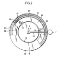
- FIG. 2 is a plan view thereof, and
- FIG. 3 is an enlarged sectional view showing a main part thereof.
- This liquid processing apparatus 100 includes a wafer holding member 1 for rotatably holding a target substrate or wafer W.
- the wafer holding member 1 is rotatable by a rotary motor 2.
- a rotary cup 3 is disposed around the wafer W held on the wafer holding member 1 and configured to rotate along with the wafer holding member 1.
- the liquid processing apparatus 100 further includes a front surface process liquid supply nozzle 4 for supplying a process liquid onto the front surface of the wafer W, and a back surface process liquid supply nozzle 5 for supplying a process liquid onto the back surface of the wafer W.
- an exhaust/drain section 6 is disposed around the rotary cup 3.
- a casing 8 is disposed to cover the area around the exhaust/drain section 6 and the area above the wafer W.
- the casing 8 is provided with a fan/filter unit (FFU) 9 at the top, so that clean air is supplied as a down flow onto the wafer W held on the wafer holding member 1.
- FFU fan/filter unit
- the wafer holding member 1 includes a rotary plate 11 formed of a circular plate set in a horizontal state.
- the center of the bottom of the rotary plate 11 is connected to a cylindrical rotary shaft 12 extending vertically downward.
- the rotary plate 11 has a circular opening 11a at the center, which communicates with a bore 12a formed inside the rotary shaft 12.
- the back surface process liquid supply nozzle 5 is movable up and down through the bore 12a and opening 11a.
- the rotary plate 11 is provided with three holding pieces 13 disposed at regular intervals for holding the outer edge of the wafer W.
- the holding pieces 13 are configured to hold the wafer W in a horizontal state such that the wafer W is slightly separated from the rotary plate 11.
- Each of the holding pieces 13 is movable by rotation between a hold position for holding the wafer W, and a release position on an outer side for releasing the wafer W.
- the rotary plate 11 has an inclined portion 11b extending in the annular direction near the outer edge such that the peripheral side is lower than the central side. Accordingly, the peripheral portion of the rotary plate 11 is thinner than the other portions.
- a belt 14 is wound around between the lower end of the rotary shaft 12 and a pulley 15 rotatable by the motor 2.
- the rotary shaft 12 is rotated through the pulley 15 and belt 14 by rotation of the motor 2.
- the front surface process liquid supply nozzle 4 is supported at the distal end of a nozzle arm 16.
- a process liquid is supplied through a liquid supply tube (not shown) into a nozzle hole formed in the nozzle 4 and is then delivered from the nozzle 4.
- the process liquid thus delivered encompasses a cleaning chemical solution, a rising liquid such as purified water, and a drying solvent such as IPA.
- the nozzle 4 is configured to selectively deliver process liquids of one, two, or more types.
- the nozzle arm 16 is rotatable about a shaft 17 used as a central axis, and is movable by a driving mechanism (not shown) between a delivery position above the center of the wafer W and a retreat position outside the wafer W. Further, the nozzle arm 16 is movable up and down, such that it is set at an upper position when it is rotated, and at a lower position when a process liquid is delivered from the front surface process liquid supply nozzle 4.
- the back surface process liquid supply nozzle 5 has a nozzle hole 5a formed therein and extending in the longitudinal direction.
- a predetermined process liquid is supplied through a process liquid tube (not shown) into the nozzle hole 5a from below and is then delivered from the nozzle hole 5a onto the back surface of the wafer W.
- the process liquid thus delivered encompasses a cleaning chemical solution, a rising liquid such as purified water, and a drying solvent such as IPA, as in the front surface process liquid supply nozzle 4.
- the nozzle 5 is configured to selectively deliver process liquids of one, two, or more types.
- the back surface process liquid supply nozzle 5 also serves as a wafer lifting member, and thus has a wafer support head 18 at the top for supporting the wafer W.
- the wafer support head 18 is provided with three wafer support pins 19 for supporting the wafer W (only two of them are shown) on the upper surface.
- the lower end of the back surface process liquid supply nozzle 5 is connected to a cylinder mechanism 21 through a connector 20.
- the back surface process liquid supply nozzle 5 is movable up and down by the cylinder mechanism 21 to move up and down the wafer W for loading and unloading the wafer W.
- the rotary cup 3 includes a cylindrical vertical wall portion 31 that extends upward from the end of the rotary plate 11 to form a vertical wall.
- An annular eaves portion 32 extends inward from the upper end of the vertical wall portion 31.
- the vertical wall portion 31 is provided with an annular and plate-like guide member 35 at a height essentially the same as the wafer W, which extends inward to a position near the peripheral edge of the wafer W.
- the guide member 35 is arranged such that the upper and lower surfaces thereof are to be almost continued to the front and back surfaces of the wafer W.
- the vertical wall portion 31 has a plurality of discharge holes 33 and 34 respectively at positions above and below the guide member 35.
- the discharge holes 33 and 34 are arrayed in the annular direction and penetrate the vertical wall portion 31 from inside to outside.
- the discharge holes 33 are arranged such that the bottom surface thereof is leveled with the upper surface of the guide member 35.
- the discharge holes 34 are arranged such that the bottom surface thereof is leveled with the upper surface of the rotary plate 11.
- a process liquid is supplied onto the center of the front surface of the wafer W from the front surface process liquid supply nozzle 4 while the wafer holding member 1 and rotary cup 3 are rotated along with the wafer W by the motor 2, the process liquid is spread by a centrifugal force on the front surface of the wafer W and is thrown off from the peripheral edge of the wafer W.
- the process liquid thus thrown off from the front surface of the wafer W is guided to the vertical wall portion 31 by the upper surface of the guide member 35 almost continued thereto. Then, the process liquid is discharged through the discharge holes 33 out of the rotary cup 3 by a centrifugal force.
- the process liquid thrown off from the front and back surfaces of the wafer W is guided by the guide member 35, the process liquid separated from the peripheral edge of the wafer W can hardly become turbulent. In this case, it is possible to guide the process liquid out of the rotary cup while preventing the process liquid from being turned into mist.
- the guide member 35 is disposed to prevent the process liquid thrown off from the front and back surfaces of the wafer W from being turned into mist. Accordingly, the upper and lower surfaces of the guide member 35 are required to have certain continuity relative to the front and back surfaces of the wafer W such that the process liquid thrown off from the front and back surfaces of the wafer W is guided without scattering mist.
- the portions of the upper and lower surfaces of the guide member 35 adjacent to the wafer W preferably have the same height levels as those of the front and back surfaces of the wafer W.
- the guide member 35 has notches 36 at positions corresponding to the wafer holding pieces 13 to accept the wafer holding pieces 13.
- the exhaust/drain section 6 is mainly used for collecting exhaust gas and drainage discharged from the space surrounded by the rotary plate 11 and rotary cup 3. As shown in the enlarged view of FIG. 3, the exhaust/drain section 6 includes an annular drain cup 41 and an annular exhaust cup 42.
- the annular drain cup 41 is disposed to receive drainage discharged from the discharge holes 33 and 34 of the vertical wall portion 31 of the rotary cup 3.
- the annular exhaust cup 42 is disposed to surround the drain cup 41.
- the drain cup 41 has a drain port 43 formed in the bottom at one position and connected to a drain tube 44.
- the drain tube 44 is connected to a suction mechanism (not shown) on the downstream side, so that drainage gathered from the rotary cup 3 into the drain cup 41 is swiftly discharged through the drain port 43 and drain tube 44 and is then discarded or recycled.
- a plurality of drain ports 43 may be used.
- the exhaust cup 42 surrounds the rotary cup 3 as well and has an upper wall 42a above the eaves portion 32.
- the exhaust cup 42 is used for collecting and exhausting gas through an opening 42b formed between the upper wall 42a and eaves portion 32.
- the exhaust cup 42 has exhaust ports 45 formed in the bottom and each connected to an exhaust tube 46.
- the exhaust tube 46 is connected to a suction mechanism (not shown) on the downstream side, so that gas is exhausted from around the rotary cup 3.
- the plurality of exhaust ports 45 can be selectively used by switching in accordance with the types of process liquids.
- the exhaust cup 42 has a plurality of air introducing ports 47 formed in the upper wall and arrayed in the annular direction.
- the exhaust cup 42 further has a plurality of air introducing ports 48 formed in the inner wall and arrayed in upper and lower rows extending in the annular direction.
- the air introducing ports 47 are used for collecting gas above the exhaust cup 42, and the air introducing ports 48 is used for collecting gas in a mechanism section present below the rotary plate 11, so as to remove gasified components of remaining process liquids. Since the exhaust cup 42 is disposed to surround the drain cup 41, it is possible to reliably collect mist of process liquids leaked out of the drain cup 41, thereby preventing the mist from diffusing outside.
- the back surface process liquid supply nozzle 5 is set at the upper position, and a wafer W is transferred from a transfer arm (not shown) onto the support pins of the wafer support head 18. Then, as shown in FIG. 4B, the back surface process liquid supply nozzle 5 is moved down to a position where the wafer W can be held by the holding pieces 13, and then the wafer W is chucked by the holding pieces 13. Then, as shown in FIG. 4C, the front surface process liquid supply nozzle 4 is moved from the retreat position to the delivery position above the center of the wafer W.
- the process liquid is supplied onto the center of the front surface and back surface of the wafer W, and is spread by a centrifugal force outward on the wafer W and thrown off from the peripheral edge of the wafer W.
- the cup surrounding the wafer W used in this process is the rotary cup 3 that is rotated along with the wafer W. Accordingly, as shown in FIG. 5, when the process liquid thrown off from the wafer W hits against the vertical wall portion 31, a centrifugal force acts on the process liquid and forms a liquid film 37 around the discharge holes 33 and 34 of the vertical wall portion 31. In this case, the process liquid is inhibited from being scattered (turned into mist), unlike a case where a stationary cup is used for the same purpose.
- the process liquid is discharged from the vertical wall portion 31 through the discharge holes 33 and 34 out of the rotary cup 3 by a centrifugal force. Consequently, it is possible to suppress such a problem caused by a stationary cup that a process liquid hitting against the cup is turned into mist and returns to the wafer W. After supply of the process liquid is stopped, part of the process liquid remaining as the liquid film 37 around the discharge holes 33 and 34 of the vertical wall portion 31 is also discharged through the discharge holes 33 and 34, so no process liquid remains in the rotary cup 3.
- the upper and lower surfaces of the guide member 35 are almost continued to the front and back surfaces of the wafer W. Accordingly, as shown in FIG. 6, when a process liquid is thrown off from the front and back surfaces of the wafer W through the peripheral edge by a centrifugal force, the liquid is guided to the vertical wall portion 31 in a laminar flow state by the upper and lower surfaces of the guide member 35, and is then discharged outside through the discharge holes 33 and 34. With this arrangement, the process liquid is effectively prevented from being turned into mist, when it is thrown off from the wafer W.
- a process liquid separated from the peripheral edge of a wafer W easily becomes turbulent and is turned into mist due to causes, such as an effect of interfacial tension at the peripheral edge of the wafer W.
- This problem is solved by the guide member 35 disposed as described above, because the guide member 35 prevents the process liquid from becoming turbulent and thereby prevents it from being turned into mist.
- a process liquid once discharged out of the rotary cup 3 may bounce back as mist from the wall of the drain cup 41 to the rotary cup 3.
- the liquid film 37 is formed on the inner surface of the vertical wall portion 31, the mist can hardly reach the inside of the rotary cup 3. Accordingly, there is no need to consider contamination of the wafer W due to mist generated inside the drain cup 41, so the drain cup 41 can be smaller, thereby making the apparatus compact.
- the exhaust cup 42 disposed to surround the drain cup 41 can trap mist leaked out of the drain cup 41, so the mist is prevented from being scattered out of the apparatus.
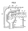
- FIG. 8 is an enlarged sectional view showing a main part of the liquid processing apparatus according to the second embodiment of the present invention.
- This embodiment differs from the first embodiment in the arrangement of the guide member, rotary cup, and exhaust/drain section. The following explanation will be focused on these differences, and the portions excluded from the explanation are arranged essentially the same as those of the first embodiment.
- a rotary cup 3' configured to guide drainage downward is used in place of the rotary cup 3 of the first embodiment.
- a guide member 35' having a lower surface inclined outward and downward is used in place of the guide member 35. Due to such different structures, a drain cup 41' employed here has a structure slightly different from the drain cup 41. Further, an exhaust cup 42' having a structure different from the exhaust cup 42 is disposed to easily guide exhaust gas to the exhaust tube (not shown).
- the rotary cup 3' includes a eaves portion 51 configured to prevent a process liquid thrown off from the wafer W from being scattered and to guide the process liquid downward.
- a plurality of spacers 55 and 56 are interposed between the eaves portion 51 and guide member 35' and between the guide member 35' and rotary plate 11 to form slits 53 and 54 for allowing process liquids to pass therethrough.
- the eaves portion 51, spacers 55, guide member 35', spacers 56, and rotary plate 11 are integratedly fixed to each other by screws or the like, so that they can be integratedly rotated.
- Each set of a plurality of spacers 55 and a plurality of spacers 56 are arrayed in the annular direction, so that each set of a plurality of slits 53 and a plurality of slits 54 are arrayed in the annular direction.
- a place having holes formed therein may be used, as in the first embodiment.
- the eaves portion 51 has an inner surface curved outward and downward, and extends to its lower end located below the rotary plate 11.
- An annular opening 57 is formed downward between the lower end of the eaves portion 51 and the rotary plate 11, i.e., at the lower end of the rotary cup 3' to discharge drainage downward.
- the drain cup 41' is disposed to receive this opening 57, i.e., to surround the opening 57.
- the lower end of the eaves portion 51 is preferably set downward as far as possible, so that it is more distant from the wafer W. Except for this portion for receiving drainage, the drain cup 41' is essentially the same as the drain cup 41 such that it includes a drain port 43 connected to a drain tube 44.
- the eaves portion 51 has an outer surface inclined outward and downward, which is continued to a curved surface extending downward.
- the exhaust cup 42' has an upper wall 42a' inclined outward and downward, which is continued to a curved surface extending downward.
- a predetermined process liquid is supplied from the front surface process liquid supply nozzle 4 and back surface process liquid supply nozzle 5 to perform a cleaning process.
- the process liquid is thrown off from the front and back surfaces of the wafer W through the peripheral edge, the liquid is guided by the upper and lower surfaces of the guide member 35'. Then, the process liquid is forced to flow through the slits 53 and 54, and is guided downward by the inner wall of the eaves portion 51. Then, the process liquid is discharged downward from the annular opening 57 formed at the lower end of the rotary cup 3' into the drain cup 41'.
- the guide member 35' provides the same function as that of the guide member 35 of the first embodiment, so the process liquid is guided from the rotary cup 3' to the drain cup 41' without becoming turbulent. Further, in this embodiment, since the process liquid is guided from the lower end of the rotary cup 3' into the drain cup 41' therebelow, even if the process liquid is turned into mist in the drain cup 41', the mist scarcely affects the wafer W, because the position of the mist is distant from the wafer W.
- the present invention is not limited to the embodiments described above, and it may be modified in various manners.
- the embodiments described above are exemplified by a liquid processing apparatus for cleaning the front and back surfaces of a wafer.
- the present invention may be applied to a liquid processing apparatus for cleaning only the front surface of a wafer.
- the present invention may be applied to a liquid processing apparatus for performing another liquid process, such as a resist liquid coating process and/or a subsequent development process.
- the target object is exemplified by a semiconductor wafer, but the present invention may be applied to another substrate, such as a substrate for flat panel display devices (FPD), a representative of which is a glass substrate for liquid crystal display devices (LCD).
- FPD flat panel display devices
- LCD liquid crystal display devices
Landscapes
- Cleaning Or Drying Semiconductors (AREA)
- Exposure Of Semiconductors, Excluding Electron Or Ion Beam Exposure (AREA)
- Weting (AREA)
- Physical Or Chemical Processes And Apparatus (AREA)
Abstract
Description
- The present invention relates to a liquid processing apparatus for performing a predetermined liquid process on a substrate, such as a semiconductor wafer. For example, this liquid process is a cleaning process for removing particles and/or contaminants deposited on a semiconductor wafer.
- In the process of manufacturing semiconductor devices or flat panel display devices (FPD), liquid processes are frequently used, in which a process liquid is supplied onto a target substrate, such as a semiconductor wafer or glass substrate. For example, processes of this kind encompass a cleaning process for removing particles and/or contaminants deposited on a substrate, and a coating process for applying a photoresist liquid or development liquid in a photolithography stage.
- As a liquid processing apparatus used for this purpose, the following apparatus is known. Specifically, a substrate, such as a semiconductor wafer, is held on a spin chuck, and a process liquid is supplied onto the front surface or front and back surfaces of the wafer, while the wafer is rotated. Consequently, a liquid film is formed on the front surface or front and back surfaces of the wafer, thereby performing a process.
- In general, an apparatus of this kind is arranged to supply a process liquid onto the center of a wafer, and rotate the wafer to spread the process liquid outward, thereby forming a liquid film and throwing off the process liquid. A surrounding member, such as a cup, is disposed around the wafer to guide downward the process liquid thrown off from the wafer, so that the process liquid is swiftly drained. However, where a cup or the like is used, part of the process liquid may bounce back to the wafer as mist, and generate defects thereon, such as water marks and/or particles.
- As a technique for preventing this problem, Jpn. Pat. Appln. KOKAI Publication
No. 8-1064 - According to this technique, the process liquid receiving member rotatable along with the substrate is disposed adjacent to the peripheral portion of the substrate. This arrangement is conceived to reliably collect the process liquid scattered around the substrate and to prevent the liquid from being redeposited on the substrate.
- However, even if the technique disclosed in Jpn. Pat. Appln. KOKAI Publication
No. 8-1064 - An object of the present invention is to provide a liquid processing apparatus arranged to supply a process liquid onto a substrate while rotating the substrate, thereby performing a liquid process on the substrate, wherein mist of the process liquid is prevented from being scattered onto the substrate.
- According to one aspect of the present invention, there is provided a liquid processing apparatus comprising: a substrate holding member configured to rotate along with a substrate held thereon in a horizontal state; a rotary cup configured to surround the substrate held on the substrate holding member and to rotate along with the substrate; a rotation mechanism configured to integratedly rotate the rotary cup and the substrate holding member; a liquid supply mechanism configured to supply a process liquid onto at least a front surface of the substrate; an exhaust/drain section configured to perform gas-exhausting and liquid-draining out of the rotary cup; and a guide member disposed to surround the substrate, having an upper surface to be substantially continued to the front surface of the substrate, and configured to rotate along with the substrate holding member and the rotary cup, such that a process liquid supplied onto the front surface of the substrate and thrown off from the substrate is guided by the upper surface of the guide member from the rotary cup to the exhaust/drain section.
- According to another aspect of the present invention, there is provided a liquid processing apparatus comprising: a substrate holding member configured to rotate along with a substrate held thereon in a horizontal state; a rotary cup configured to surround the substrate held on the substrate holding member and to rotate along with the substrate; a rotation mechanism configured to integratedly rotate the rotary cup and the substrate holding member; a front surface liquid supply mechanism configured to supply a process liquid onto a front surface of the substrate; a back surface liquid supply mechanism configured to supply a process liquid onto a back surface of the substrate; an exhaust/drain section configured to perform gas-exhausting and liquid-draining out of the rotary cup; and a guide member disposed to surround the substrate, having upper and lower surfaces to be substantially continued to the front and back surfaces of the substrate, respectively, and configured to rotate along with the substrate holding member and the rotary cup, such that a process liquid supplied onto the front surface of the substrate and thrown off from the substrate is guided by the upper surface of the guide member from the rotary cup to the exhaust/drain section, and a process liquid supplied onto the back surface of the substrate and thrown off from the substrate is guided by the lower surface of the guide member from the rotary cup to the exhaust/drain section.
- The inventors of the present invention studied problems in this field and have arrived at the findings given below. Specifically, when a process liquid is separated from a substrate by rotation of the substrate, the flow of the liquid is suddenly changed from a laminar flow state to an uneven flow state near the peripheral edge of the substrate, due to causes, such as an effect of interfacial tension at the peripheral edge of the substrate. Consequently, the flow of gas also tends to become turbulent near the peripheral edge of the substrate and generate mist of the liquid. The present invention is conceived to solve this problem.
- Specifically, according to the present invention, since the rotary cup is rotated along with the substrate, a centrifugal force acts on the rotary cup, so mist of a process liquid is inhibited from bouncing back, unlike a case where a stationary cup is used for the same purpose. Further, a process liquid thrown off from the front surface or the front and back surfaces of the substrate is guided in a laminar flow state by the guide member from the rotary cup to the exhaust/drain section. In this case, the process liquid is inhibited from being turned into mist when the process liquid is thrown off from the substrate. Consequently, it is possible to prevent mist of the process liquid from being scattered on and around the substrate during a liquid process in a most effective way.
-
- FIG. 1 is a sectional view schematically showing the structure of a liquid processing apparatus according to a first embodiment of the present invention;
- FIG. 2 is a partially sectional plan view schematically showing the liquid processing apparatus according to the first embodiment of the present invention;
- FIG. 3 is an enlarged sectional view showing a main part of the liquid processing apparatus shown in FIG. 1;
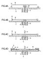
- FIGS. 4A to 4D are views for explaining an operation of the liquid processing apparatus according to the first embodiment of the present invention;
- FIG. 5 is a view for explaining a state of a process liquid thrown off from a wafer;
- FIG. 6 is a view for explaining an effect of a guide member;
- FIG. 7 is a view for explaining a state of a process liquid thrown off from a wafer, where no guide member is present;
- FIG. 8 is an enlarged sectional view showing a main part of a liquid processing apparatus according to a second embodiment of the present invention.
- Embodiments of the present invention will now be described with reference to the accompanying drawings. Hereinafter, an explanation will be given of a case where the present invention is applied to a liquid processing apparatus that can perform a cleaning process on the front and back surfaces of a semiconductor wafer (which will be simply referred to as "wafer", hereinafter).
- FIG. 1 is a sectional view schematically showing the structure of a liquid processing apparatus according to a first embodiment of the present invention. FIG. 2 is a plan view thereof, and FIG. 3 is an enlarged sectional view showing a main part thereof. This
liquid processing apparatus 100 includes a wafer holding member 1 for rotatably holding a target substrate or wafer W. The wafer holding member 1 is rotatable by arotary motor 2. Arotary cup 3 is disposed around the wafer W held on the wafer holding member 1 and configured to rotate along with the wafer holding member 1. Theliquid processing apparatus 100 further includes a front surface processliquid supply nozzle 4 for supplying a process liquid onto the front surface of the wafer W, and a back surface processliquid supply nozzle 5 for supplying a process liquid onto the back surface of the wafer W. Further, an exhaust/drain section 6 is disposed around therotary cup 3. Acasing 8 is disposed to cover the area around the exhaust/drain section 6 and the area above the wafer W. Thecasing 8 is provided with a fan/filter unit (FFU) 9 at the top, so that clean air is supplied as a down flow onto the wafer W held on the wafer holding member 1. - The wafer holding member 1 includes a
rotary plate 11 formed of a circular plate set in a horizontal state. The center of the bottom of therotary plate 11 is connected to a cylindricalrotary shaft 12 extending vertically downward. Therotary plate 11 has acircular opening 11a at the center, which communicates with abore 12a formed inside therotary shaft 12. The back surface processliquid supply nozzle 5 is movable up and down through thebore 12a and opening 11a. As shown in FIG. 2, therotary plate 11 is provided with threeholding pieces 13 disposed at regular intervals for holding the outer edge of the wafer W. Theholding pieces 13 are configured to hold the wafer W in a horizontal state such that the wafer W is slightly separated from therotary plate 11. Each of the holdingpieces 13 is movable by rotation between a hold position for holding the wafer W, and a release position on an outer side for releasing the wafer W. Therotary plate 11 has aninclined portion 11b extending in the annular direction near the outer edge such that the peripheral side is lower than the central side. Accordingly, the peripheral portion of therotary plate 11 is thinner than the other portions. - A
belt 14 is wound around between the lower end of therotary shaft 12 and apulley 15 rotatable by themotor 2. Therotary shaft 12 is rotated through thepulley 15 andbelt 14 by rotation of themotor 2. - The front surface process
liquid supply nozzle 4 is supported at the distal end of anozzle arm 16. A process liquid is supplied through a liquid supply tube (not shown) into a nozzle hole formed in thenozzle 4 and is then delivered from thenozzle 4. For example, the process liquid thus delivered encompasses a cleaning chemical solution, a rising liquid such as purified water, and a drying solvent such as IPA. In other words, thenozzle 4 is configured to selectively deliver process liquids of one, two, or more types. As shown in FIG. 2, thenozzle arm 16 is rotatable about ashaft 17 used as a central axis, and is movable by a driving mechanism (not shown) between a delivery position above the center of the wafer W and a retreat position outside the wafer W. Further, thenozzle arm 16 is movable up and down, such that it is set at an upper position when it is rotated, and at a lower position when a process liquid is delivered from the front surface processliquid supply nozzle 4. - The back surface process
liquid supply nozzle 5 has anozzle hole 5a formed therein and extending in the longitudinal direction. A predetermined process liquid is supplied through a process liquid tube (not shown) into thenozzle hole 5a from below and is then delivered from thenozzle hole 5a onto the back surface of the wafer W. For example, the process liquid thus delivered encompasses a cleaning chemical solution, a rising liquid such as purified water, and a drying solvent such as IPA, as in the front surface processliquid supply nozzle 4. In other words, thenozzle 5 is configured to selectively deliver process liquids of one, two, or more types. The back surface processliquid supply nozzle 5 also serves as a wafer lifting member, and thus has awafer support head 18 at the top for supporting the wafer W. Thewafer support head 18 is provided with three wafer support pins 19 for supporting the wafer W (only two of them are shown) on the upper surface. The lower end of the back surface processliquid supply nozzle 5 is connected to acylinder mechanism 21 through aconnector 20. The back surface processliquid supply nozzle 5 is movable up and down by thecylinder mechanism 21 to move up and down the wafer W for loading and unloading the wafer W. - As shown in FIG. 3, the
rotary cup 3 includes a cylindricalvertical wall portion 31 that extends upward from the end of therotary plate 11 to form a vertical wall. Anannular eaves portion 32 extends inward from the upper end of thevertical wall portion 31. - The
vertical wall portion 31 is provided with an annular and plate-like guide member 35 at a height essentially the same as the wafer W, which extends inward to a position near the peripheral edge of the wafer W. In other words, theguide member 35 is arranged such that the upper and lower surfaces thereof are to be almost continued to the front and back surfaces of the wafer W. Thevertical wall portion 31 has a plurality of discharge holes 33 and 34 respectively at positions above and below theguide member 35. The discharge holes 33 and 34 are arrayed in the annular direction and penetrate thevertical wall portion 31 from inside to outside. The discharge holes 33 are arranged such that the bottom surface thereof is leveled with the upper surface of theguide member 35. The discharge holes 34 are arranged such that the bottom surface thereof is leveled with the upper surface of therotary plate 11. When a process liquid is supplied onto the center of the front surface of the wafer W from the front surface processliquid supply nozzle 4 while the wafer holding member 1 androtary cup 3 are rotated along with the wafer W by themotor 2, the process liquid is spread by a centrifugal force on the front surface of the wafer W and is thrown off from the peripheral edge of the wafer W. The process liquid thus thrown off from the front surface of the wafer W is guided to thevertical wall portion 31 by the upper surface of theguide member 35 almost continued thereto. Then, the process liquid is discharged through the discharge holes 33 out of therotary cup 3 by a centrifugal force. Similarly, when a process liquid is supplied onto the center of the back surface of the wafer W from the back surface processliquid supply nozzle 5 while the wafer holding member 1 androtary cup 3 are rotated along with the wafer W, the process liquid is spread by a centrifugal force on the back surface of the wafer W and is thrown off from the peripheral edge of the wafer W. The process liquid thus thrown off from the back surface of the wafer W is guided to thevertical wall portion 31 by the lower surface of theguide member 35 almost continued thereto. Then, the process liquid is discharged through the discharge holes 34 out of therotary cup 3 by a centrifugal force. At this time, since a centrifugal force acts on thevertical wall portion 31, mist of the process liquid is inhibited from returning inward. - Further, since the process liquid thrown off from the front and back surfaces of the wafer W is guided by the
guide member 35, the process liquid separated from the peripheral edge of the wafer W can hardly become turbulent. In this case, it is possible to guide the process liquid out of the rotary cup while preventing the process liquid from being turned into mist. As described above, theguide member 35 is disposed to prevent the process liquid thrown off from the front and back surfaces of the wafer W from being turned into mist. Accordingly, the upper and lower surfaces of theguide member 35 are required to have certain continuity relative to the front and back surfaces of the wafer W such that the process liquid thrown off from the front and back surfaces of the wafer W is guided without scattering mist. Particularly, the portions of the upper and lower surfaces of theguide member 35 adjacent to the wafer W preferably have the same height levels as those of the front and back surfaces of the wafer W. As shown in FIG. 2, theguide member 35 hasnotches 36 at positions corresponding to thewafer holding pieces 13 to accept thewafer holding pieces 13. - The exhaust/
drain section 6 is mainly used for collecting exhaust gas and drainage discharged from the space surrounded by therotary plate 11 androtary cup 3. As shown in the enlarged view of FIG. 3, the exhaust/drain section 6 includes anannular drain cup 41 and anannular exhaust cup 42. Theannular drain cup 41 is disposed to receive drainage discharged from the discharge holes 33 and 34 of thevertical wall portion 31 of therotary cup 3. Theannular exhaust cup 42 is disposed to surround thedrain cup 41. Thedrain cup 41 has adrain port 43 formed in the bottom at one position and connected to adrain tube 44. Thedrain tube 44 is connected to a suction mechanism (not shown) on the downstream side, so that drainage gathered from therotary cup 3 into thedrain cup 41 is swiftly discharged through thedrain port 43 anddrain tube 44 and is then discarded or recycled. In place of asingle drain port 43, a plurality ofdrain ports 43 may be used. Theexhaust cup 42 surrounds therotary cup 3 as well and has anupper wall 42a above theeaves portion 32. Theexhaust cup 42 is used for collecting and exhausting gas through anopening 42b formed between theupper wall 42a andeaves portion 32. Theexhaust cup 42 hasexhaust ports 45 formed in the bottom and each connected to anexhaust tube 46. Theexhaust tube 46 is connected to a suction mechanism (not shown) on the downstream side, so that gas is exhausted from around therotary cup 3. The plurality ofexhaust ports 45 can be selectively used by switching in accordance with the types of process liquids. As shown in FIG. 3, theexhaust cup 42 has a plurality ofair introducing ports 47 formed in the upper wall and arrayed in the annular direction. Theexhaust cup 42 further has a plurality ofair introducing ports 48 formed in the inner wall and arrayed in upper and lower rows extending in the annular direction. Theair introducing ports 47 are used for collecting gas above theexhaust cup 42, and theair introducing ports 48 is used for collecting gas in a mechanism section present below therotary plate 11, so as to remove gasified components of remaining process liquids. Since theexhaust cup 42 is disposed to surround thedrain cup 41, it is possible to reliably collect mist of process liquids leaked out of thedrain cup 41, thereby preventing the mist from diffusing outside. - Next, an explanation will be given, with reference to FIGS. 4A to 4D, of an operation of the
liquid processing apparatus 100 having the structure described above. At first, as shown in FIG. 4A, the back surface processliquid supply nozzle 5 is set at the upper position, and a wafer W is transferred from a transfer arm (not shown) onto the support pins of thewafer support head 18. Then, as shown in FIG. 4B, the back surface processliquid supply nozzle 5 is moved down to a position where the wafer W can be held by the holdingpieces 13, and then the wafer W is chucked by the holdingpieces 13. Then, as shown in FIG. 4C, the front surface processliquid supply nozzle 4 is moved from the retreat position to the delivery position above the center of the wafer W. - In this state, as shown in FIG. 4D, while the holding member 1 is rotated along with the
rotary cup 3 and wafer W by themotor 2, a predetermined process liquid is supplied from the front surface processliquid supply nozzle 4 and back surface processliquid supply nozzle 5 to perform a cleaning process. - In this cleaning process, the process liquid is supplied onto the center of the front surface and back surface of the wafer W, and is spread by a centrifugal force outward on the wafer W and thrown off from the peripheral edge of the wafer W. The cup surrounding the wafer W used in this process is the
rotary cup 3 that is rotated along with the wafer W. Accordingly, as shown in FIG. 5, when the process liquid thrown off from the wafer W hits against thevertical wall portion 31, a centrifugal force acts on the process liquid and forms aliquid film 37 around the discharge holes 33 and 34 of thevertical wall portion 31. In this case, the process liquid is inhibited from being scattered (turned into mist), unlike a case where a stationary cup is used for the same purpose. Then, the process liquid is discharged from thevertical wall portion 31 through the discharge holes 33 and 34 out of therotary cup 3 by a centrifugal force. Consequently, it is possible to suppress such a problem caused by a stationary cup that a process liquid hitting against the cup is turned into mist and returns to the wafer W. After supply of the process liquid is stopped, part of the process liquid remaining as theliquid film 37 around the discharge holes 33 and 34 of thevertical wall portion 31 is also discharged through the discharge holes 33 and 34, so no process liquid remains in therotary cup 3. - The upper and lower surfaces of the
guide member 35 are almost continued to the front and back surfaces of the wafer W. Accordingly, as shown in FIG. 6, when a process liquid is thrown off from the front and back surfaces of the wafer W through the peripheral edge by a centrifugal force, the liquid is guided to thevertical wall portion 31 in a laminar flow state by the upper and lower surfaces of theguide member 35, and is then discharged outside through the discharge holes 33 and 34. With this arrangement, the process liquid is effectively prevented from being turned into mist, when it is thrown off from the wafer W. - As shown in FIG. 7, where no
guide member 35 is present, a process liquid separated from the peripheral edge of a wafer W easily becomes turbulent and is turned into mist due to causes, such as an effect of interfacial tension at the peripheral edge of the wafer W. This problem is solved by theguide member 35 disposed as described above, because theguide member 35 prevents the process liquid from becoming turbulent and thereby prevents it from being turned into mist. - As described above, due to a synergistic action of the
rotary cup 3 with theguide member 35, it is possible to prevent mist of a process liquid from being scattered near the wafer W in a most effective way. - According to the structure of the apparatus shown in FIG. 1, a process liquid once discharged out of the
rotary cup 3 may bounce back as mist from the wall of thedrain cup 41 to therotary cup 3. However, since theliquid film 37 is formed on the inner surface of thevertical wall portion 31, the mist can hardly reach the inside of therotary cup 3. Accordingly, there is no need to consider contamination of the wafer W due to mist generated inside thedrain cup 41, so thedrain cup 41 can be smaller, thereby making the apparatus compact. - Further, even if the size of the
drain cup 41 is decreased, theexhaust cup 42 disposed to surround thedrain cup 41 can trap mist leaked out of thedrain cup 41, so the mist is prevented from being scattered out of the apparatus. - Next, an explanation will be given of a liquid processing apparatus according to a second embodiment of the present invention.
- FIG. 8 is an enlarged sectional view showing a main part of the liquid processing apparatus according to the second embodiment of the present invention. This embodiment differs from the first embodiment in the arrangement of the guide member, rotary cup, and exhaust/drain section. The following explanation will be focused on these differences, and the portions excluded from the explanation are arranged essentially the same as those of the first embodiment.
- In this embodiment, a rotary cup 3' configured to guide drainage downward is used in place of the
rotary cup 3 of the first embodiment. Further, a guide member 35' having a lower surface inclined outward and downward is used in place of theguide member 35. Due to such different structures, a drain cup 41' employed here has a structure slightly different from thedrain cup 41. Further, an exhaust cup 42' having a structure different from theexhaust cup 42 is disposed to easily guide exhaust gas to the exhaust tube (not shown). - Specifically, the rotary cup 3' includes a
eaves portion 51 configured to prevent a process liquid thrown off from the wafer W from being scattered and to guide the process liquid downward. A plurality ofspacers eaves portion 51 and guide member 35' and between the guide member 35' androtary plate 11 to formslits eaves portion 51,spacers 55, guide member 35',spacers 56, androtary plate 11 are integratedly fixed to each other by screws or the like, so that they can be integratedly rotated. Each set of a plurality ofspacers 55 and a plurality ofspacers 56 are arrayed in the annular direction, so that each set of a plurality ofslits 53 and a plurality ofslits 54 are arrayed in the annular direction. In place of these spacers, a place having holes formed therein may be used, as in the first embodiment. - The
eaves portion 51 has an inner surface curved outward and downward, and extends to its lower end located below therotary plate 11. Anannular opening 57 is formed downward between the lower end of theeaves portion 51 and therotary plate 11, i.e., at the lower end of the rotary cup 3' to discharge drainage downward. The drain cup 41' is disposed to receive thisopening 57, i.e., to surround theopening 57. Where theeaves portion 51 extends to its lower end located below therotary plate 11, the portion for discharging drainage from the rotary cup 3' becomes distant from the wafer W, thereby decreasing return of the mist. In light of this, the lower end of theeaves portion 51 is preferably set downward as far as possible, so that it is more distant from the wafer W. Except for this portion for receiving drainage, the drain cup 41' is essentially the same as thedrain cup 41 such that it includes adrain port 43 connected to adrain tube 44. - The
eaves portion 51 has an outer surface inclined outward and downward, which is continued to a curved surface extending downward. In accordance with the inclination of theeaves portion 51, the exhaust cup 42' has anupper wall 42a' inclined outward and downward, which is continued to a curved surface extending downward. With this arrangement, gas collected through anopening 42b' formed between theupper wall 42a' andeaves portion 51 is easily guided to an exhaust tube (not shown). - According to the liquid processing apparatus having the structure described above, as in the first embodiment, while the holding member 1 is rotated along with the rotary cup 3' and wafer W by the
motor 2, a predetermined process liquid is supplied from the front surface processliquid supply nozzle 4 and back surface processliquid supply nozzle 5 to perform a cleaning process. When the process liquid is thrown off from the front and back surfaces of the wafer W through the peripheral edge, the liquid is guided by the upper and lower surfaces of the guide member 35'. Then, the process liquid is forced to flow through theslits eaves portion 51. Then, the process liquid is discharged downward from theannular opening 57 formed at the lower end of the rotary cup 3' into the drain cup 41'. In this embodiment, the guide member 35' provides the same function as that of theguide member 35 of the first embodiment, so the process liquid is guided from the rotary cup 3' to the drain cup 41' without becoming turbulent. Further, in this embodiment, since the process liquid is guided from the lower end of the rotary cup 3' into the drain cup 41' therebelow, even if the process liquid is turned into mist in the drain cup 41', the mist scarcely affects the wafer W, because the position of the mist is distant from the wafer W. - The present invention is not limited to the embodiments described above, and it may be modified in various manners. For example, the embodiments described above are exemplified by a liquid processing apparatus for cleaning the front and back surfaces of a wafer. However, the present invention may be applied to a liquid processing apparatus for cleaning only the front surface of a wafer. Further, in place of a cleaning process, the present invention may be applied to a liquid processing apparatus for performing another liquid process, such as a resist liquid coating process and/or a subsequent development process. In the embodiments described above, the target object is exemplified by a semiconductor wafer, but the present invention may be applied to another substrate, such as a substrate for flat panel display devices (FPD), a representative of which is a glass substrate for liquid crystal display devices (LCD).
Claims (8)
- A liquid processing apparatus comprising:a substrate holding member configured to rotate along with a substrate held thereon in a horizontal state;a rotary cup configured to surround the substrate held on the substrate holding member and to rotate along with the substrate;a rotation mechanism configured to integratedly rotate the rotary cup and the substrate holding member;a liquid supply mechanism configured to supply a process liquid onto at least a front surface of the substrate;an exhaust/drain section configured to perform gas-exhausting and liquid-draining out of the rotary cup; anda guide member disposed to surround the substrate, having an upper surface to be substantially continued to the front surface of the substrate, and configured to rotate along with the substrate holding member and the rotary cup, such that a process liquid supplied onto the front surface of the substrate and thrown off from the substrate is guided by the upper surface of the guide member from the rotary cup to the exhaust/drain section.
- The liquid processing apparatus according to claim 1, wherein the guide member is arranged such that a portion of the upper surface adjacent to the substrate has essentially the same height level as that of the front surface of the substrate.
- A liquid processing apparatus comprising:a substrate holding member configured to rotate along with a substrate held thereon in a horizontal state;a rotary cup configured to surround the substrate held on the substrate holding member and to rotate along with the substrate;a rotation mechanism configured to integratedly rotate the rotary cup and the substrate holding member;a front surface liquid supply mechanism configured to supply a process liquid onto a front surface of the substrate;a back surface liquid supply mechanism configured to supply a process liquid onto a back surface of the substrate;an exhaust/drain section configured to perform gas-exhausting and liquid-draining out of the rotary cup; anda guide member disposed to surround the substrate, having upper and lower surfaces to be substantially continued to the front and back surfaces of the substrate, respectively, and configured to rotate along with the substrate holding member and the rotary cup, such that a process liquid supplied onto the front surface of the substrate and thrown off from the substrate is guided by the upper surface of the guide member from the rotary cup to the exhaust/drain section, and a process liquid supplied onto the back surface of the substrate and thrown off from the substrate is guided by the lower surface of the guide member from the rotary cup to the exhaust/drain section.
- The liquid processing apparatus according to claim 1 or 3, wherein the guide member is arranged such that portions of the upper and lower surfaces adjacent to the substrate have essentially the same height levels as those of the front and back surfaces of the substrate.
- The liquid processing apparatus according to claim 1 or 3, wherein the guide member comprises an annular plate body having an inner end adjacent to the substrate.
- The liquid processing apparatus according to claim 1 or 3, wherein the rotary cup comprises a process liquid discharge portion configured to discharge in a horizontal direction a process liquid thrown off from the substrate.
- The liquid processing apparatus according to claim 1 or 3, wherein the rotary cup comprises a guide wall configured to receive and guide downward a process liquid thrown off from the substrate, and an opening configured to discharge downward a process liquid thus received.
- The liquid processing apparatus according to claim 1 or 3, wherein the exhaust/drain section comprises an annular drain cup configured to receive drainage thrown off from the substrate, and an exhaust cup disposed outside the drain cup and configured to discharge gas from the rotary cup.
Applications Claiming Priority (1)
| Application Number | Priority Date | Filing Date | Title |
|---|---|---|---|
| JP2006114960 | 2006-04-18 |
Publications (2)
| Publication Number | Publication Date |
|---|---|
| EP1848025A1 true EP1848025A1 (en) | 2007-10-24 |
| EP1848025B1 EP1848025B1 (en) | 2009-12-02 |
Family
ID=38120656
Family Applications (1)
| Application Number | Title | Priority Date | Filing Date |
|---|---|---|---|
| EP07007786A Not-in-force EP1848025B1 (en) | 2006-04-18 | 2007-04-17 | Liquid processing apparatus |
Country Status (7)
| Country | Link |
|---|---|
| US (1) | US7998308B2 (en) |
| EP (1) | EP1848025B1 (en) |
| KR (1) | KR101019445B1 (en) |
| CN (2) | CN101060070B (en) |
| AT (1) | ATE450885T1 (en) |
| DE (1) | DE602007003506D1 (en) |
| TW (1) | TW200802579A (en) |
Cited By (1)
| Publication number | Priority date | Publication date | Assignee | Title |
|---|---|---|---|---|
| EP4002433A1 (en) * | 2020-11-17 | 2022-05-25 | SPTS Technologies Limited | Spin rinse dryer with improved drying characteristics |
Families Citing this family (36)
| Publication number | Priority date | Publication date | Assignee | Title |
|---|---|---|---|---|
| EP1848025B1 (en) * | 2006-04-18 | 2009-12-02 | Tokyo Electron Limited | Liquid processing apparatus |
| US8580042B2 (en) | 2007-12-10 | 2013-11-12 | Acm Research (Shanghai) Inc. | Methods and apparatus for cleaning semiconductor wafers |
| WO2009084406A1 (en) * | 2007-12-27 | 2009-07-09 | Tokyo Electron Limited | Liquid treatment apparatus, liquid treatment method and storage medium |
| KR100969604B1 (en) * | 2008-06-26 | 2010-07-12 | 주식회사 에이앤디코퍼레이션 | Substrate processing apparatus and method |
| JP5156661B2 (en) * | 2009-02-12 | 2013-03-06 | 東京エレクトロン株式会社 | Liquid processing apparatus and liquid processing method |
| JP5310693B2 (en) * | 2010-10-07 | 2013-10-09 | 東京エレクトロン株式会社 | Liquid processing equipment |
| US9799537B2 (en) * | 2010-12-03 | 2017-10-24 | Applied Materials, Inc. | Processing assembly for semiconductor workpiece and methods of processing same |
| US20120286481A1 (en) * | 2011-05-13 | 2012-11-15 | Lam Research Ag | Device and process for liquid treatment of wafer shaped articles |
| US20120305036A1 (en) * | 2011-06-01 | 2012-12-06 | Lam Research Ag | Device for treating surfaces of wafer-shaped articles |
| JP5645796B2 (en) * | 2011-11-21 | 2014-12-24 | 東京エレクトロン株式会社 | Liquid processing apparatus and liquid processing method |
| JP5913937B2 (en) * | 2011-11-30 | 2016-05-11 | 株式会社Screenセミコンダクターソリューションズ | Cup and substrate processing equipment |
| JP6148475B2 (en) * | 2013-01-25 | 2017-06-14 | 株式会社東芝 | Semiconductor manufacturing apparatus and semiconductor device manufacturing method |
| JP6057334B2 (en) * | 2013-03-15 | 2017-01-11 | 株式会社Screenホールディングス | Substrate processing equipment |
| JP6281161B2 (en) * | 2013-09-27 | 2018-02-21 | 東京エレクトロン株式会社 | Liquid processing equipment |
| JP6229933B2 (en) * | 2013-09-27 | 2017-11-15 | 株式会社Screenホールディングス | Processing cup cleaning method, substrate processing method, and substrate processing apparatus |
| TWI569349B (en) * | 2013-09-27 | 2017-02-01 | 斯克林集團公司 | Substrate processing apparatus and substrate processing method |
| JP6090113B2 (en) * | 2013-10-30 | 2017-03-08 | 東京エレクトロン株式会社 | Liquid processing equipment |
| JP6134673B2 (en) | 2014-03-13 | 2017-05-24 | 株式会社Screenホールディングス | Substrate processing equipment |
| US10576604B2 (en) * | 2014-04-30 | 2020-03-03 | Ebara Corporation | Substrate polishing apparatus |
| JP6267141B2 (en) * | 2014-06-04 | 2018-01-24 | 東京エレクトロン株式会社 | Liquid coating method, liquid coating apparatus, and computer-readable recording medium |
| KR101621482B1 (en) * | 2014-09-30 | 2016-05-17 | 세메스 주식회사 | Apparatus and Method for treating substrate |
| JP6797526B2 (en) * | 2014-11-11 | 2020-12-09 | 株式会社荏原製作所 | Substrate cleaning equipment |
| US10276425B2 (en) * | 2014-11-21 | 2019-04-30 | Tokyo Electron Limited | Substrate processing system |
| CN108140603B (en) * | 2015-10-04 | 2023-02-28 | 应用材料公司 | Substrate supports and baffle equipment |
| CN105244304B (en) * | 2015-11-11 | 2018-12-18 | 北京七星华创电子股份有限公司 | A kind of static electrification liquid mist cleaning device and cleaning method |
| CN110021535A (en) * | 2018-01-10 | 2019-07-16 | 弘塑科技股份有限公司 | Substrate board treatment and its turntable |
| EP3543795A1 (en) * | 2018-03-20 | 2019-09-25 | Patek Philippe SA Genève | Method for manufacturing silicon clock components |
| CN109411402B (en) * | 2018-08-08 | 2021-03-30 | 中芯集成电路(宁波)有限公司 | Wet cleaning equipment |
| JP7037459B2 (en) * | 2018-09-10 | 2022-03-16 | キオクシア株式会社 | Semiconductor manufacturing equipment and methods for manufacturing semiconductor equipment |
| JP7192756B2 (en) * | 2019-12-19 | 2022-12-20 | 株式会社Sumco | Vapor deposition apparatus and vapor deposition method |
| JP7438015B2 (en) * | 2020-05-01 | 2024-02-26 | 東京エレクトロン株式会社 | Substrate processing equipment |
| KR102732711B1 (en) | 2020-09-16 | 2024-11-20 | 삼성전자주식회사 | Wafer cleaning apparatus and wafer cleaning method using the same |
| CN112670207B (en) * | 2020-12-21 | 2023-10-31 | 长江存储科技有限责任公司 | Wafer edge processing equipment and processing method of wafer structure to be processed |
| CN112992733B (en) * | 2021-02-08 | 2022-03-11 | 江苏亚电科技有限公司 | A brush cleaning device for wafer processing |
| JP7731250B2 (en) * | 2021-09-22 | 2025-08-29 | 株式会社Screenホールディングス | Substrate Processing Equipment |
| KR102629496B1 (en) * | 2021-12-24 | 2024-01-29 | 세메스 주식회사 | A home pot and an apparatus for treating a substrate |
Citations (4)
| Publication number | Priority date | Publication date | Assignee | Title |
|---|---|---|---|---|
| US5997653A (en) * | 1996-10-07 | 1999-12-07 | Tokyo Electron Limited | Method for washing and drying substrates |
| EP1335412A2 (en) * | 2002-01-30 | 2003-08-13 | Dainippon Screen Mfg. Co., Ltd. | Substrate treatment apparatus and substrate treatment method |
| US20030168089A1 (en) | 1999-10-06 | 2003-09-11 | Ichiro Katakabe | Method of and apparatus for cleaning substrate |
| US20040180141A1 (en) | 2003-03-10 | 2004-09-16 | Shinji Kobayashi | Coating and processing apparatus and method |
Family Cites Families (13)
| Publication number | Priority date | Publication date | Assignee | Title |
|---|---|---|---|---|
| JP3138897B2 (en) | 1993-10-07 | 2001-02-26 | 大日本スクリーン製造株式会社 | Rotary substrate processing equipment |
| US5718763A (en) * | 1994-04-04 | 1998-02-17 | Tokyo Electron Limited | Resist processing apparatus for a rectangular substrate |
| JP3102831B2 (en) | 1994-06-20 | 2000-10-23 | 大日本スクリーン製造株式会社 | Rotary processing equipment |
| JPH0878368A (en) | 1994-09-07 | 1996-03-22 | Hitachi Ltd | Workpiece processing method and device |
| US6350319B1 (en) * | 1998-03-13 | 2002-02-26 | Semitool, Inc. | Micro-environment reactor for processing a workpiece |
| US6827814B2 (en) * | 2000-05-08 | 2004-12-07 | Tokyo Electron Limited | Processing apparatus, processing system and processing method |
| JP3837017B2 (en) | 2000-12-04 | 2006-10-25 | 大日本スクリーン製造株式会社 | Substrate processing apparatus, substrate processing method, and substrate processing apparatus cleaning method |
| JP2002176026A (en) * | 2000-12-05 | 2002-06-21 | Ses Co Ltd | Single wafer type substrate cleaning method and single wafer type substrate cleaning apparatus |
| JP3958539B2 (en) * | 2001-08-02 | 2007-08-15 | 東京エレクトロン株式会社 | Substrate processing apparatus and substrate processing method |
| JP4018958B2 (en) * | 2001-10-30 | 2007-12-05 | 大日本スクリーン製造株式会社 | Substrate processing equipment |
| EP1848025B1 (en) * | 2006-04-18 | 2009-12-02 | Tokyo Electron Limited | Liquid processing apparatus |
| CN100550291C (en) * | 2006-06-16 | 2009-10-14 | 东京毅力科创株式会社 | Liquid processing device and liquid processing method |
| KR100979979B1 (en) * | 2006-07-26 | 2010-09-03 | 도쿄엘렉트론가부시키가이샤 | Liquid treatment device and liquid treatment method |
-
2007
- 2007-04-17 EP EP07007786A patent/EP1848025B1/en not_active Not-in-force
- 2007-04-17 KR KR1020070037458A patent/KR101019445B1/en active Active
- 2007-04-17 DE DE602007003506T patent/DE602007003506D1/en active Active
- 2007-04-17 TW TW096113508A patent/TW200802579A/en unknown
- 2007-04-17 AT AT07007786T patent/ATE450885T1/en active
- 2007-04-17 US US11/785,351 patent/US7998308B2/en active Active
- 2007-04-18 CN CN2007100961916A patent/CN101060070B/en active Active
- 2007-04-18 CN CN2008101795797A patent/CN101441991B/en active Active
Patent Citations (4)
| Publication number | Priority date | Publication date | Assignee | Title |
|---|---|---|---|---|
| US5997653A (en) * | 1996-10-07 | 1999-12-07 | Tokyo Electron Limited | Method for washing and drying substrates |
| US20030168089A1 (en) | 1999-10-06 | 2003-09-11 | Ichiro Katakabe | Method of and apparatus for cleaning substrate |
| EP1335412A2 (en) * | 2002-01-30 | 2003-08-13 | Dainippon Screen Mfg. Co., Ltd. | Substrate treatment apparatus and substrate treatment method |
| US20040180141A1 (en) | 2003-03-10 | 2004-09-16 | Shinji Kobayashi | Coating and processing apparatus and method |
Cited By (1)
| Publication number | Priority date | Publication date | Assignee | Title |
|---|---|---|---|---|
| EP4002433A1 (en) * | 2020-11-17 | 2022-05-25 | SPTS Technologies Limited | Spin rinse dryer with improved drying characteristics |
Also Published As
| Publication number | Publication date |
|---|---|
| CN101441991B (en) | 2010-11-03 |
| CN101441991A (en) | 2009-05-27 |
| CN101060070A (en) | 2007-10-24 |
| CN101060070B (en) | 2010-10-27 |
| KR101019445B1 (en) | 2011-03-07 |
| US20070240824A1 (en) | 2007-10-18 |
| TW200802579A (en) | 2008-01-01 |
| TWI362068B (en) | 2012-04-11 |
| DE602007003506D1 (en) | 2010-01-14 |
| KR20070103314A (en) | 2007-10-23 |
| ATE450885T1 (en) | 2009-12-15 |
| US7998308B2 (en) | 2011-08-16 |
| EP1848025B1 (en) | 2009-12-02 |
Similar Documents
| Publication | Publication Date | Title |
|---|---|---|
| EP1848025B1 (en) | Liquid processing apparatus | |
| US7793610B2 (en) | Liquid processing apparatus | |
| US8479753B2 (en) | Liquid processing apparatus and method | |
| US8043440B2 (en) | Cleaning apparatus and method and computer readable medium | |
| US8152933B2 (en) | Substrate processing apparatus, substrate processing method, and drain cup cleaning method | |
| US8051862B2 (en) | Liquid processing apparatus and liquid processing method | |
| KR101062253B1 (en) | Liquid treatment device | |
| US20090031948A1 (en) | Substrate processing apparatus | |
| JP4933945B2 (en) | Liquid processing equipment | |
| CN107851572A (en) | Substrate processing apparatus, substrate processing method, and storage medium | |
| WO2014092160A1 (en) | Substrate liquid processing apparatus and substrate liquid processing method | |
| JP5036415B2 (en) | Liquid processing apparatus and liquid processing method | |
| JP2009224692A (en) | Substrate processor and substrate processing method | |
| JP4804407B2 (en) | Liquid processing equipment | |
| JP4805003B2 (en) | Liquid processing equipment | |
| JP4832176B2 (en) | Liquid processing apparatus and liquid processing method | |
| JP4912020B2 (en) | Liquid processing equipment | |
| JP2024143419A (en) | SUBSTRATE PROCESSING APPARATUS AND SUBSTRATE PROCESSING METHOD |
Legal Events
| Date | Code | Title | Description |
|---|---|---|---|
| PUAI | Public reference made under article 153(3) epc to a published international application that has entered the european phase |
Free format text: ORIGINAL CODE: 0009012 |
|
| AK | Designated contracting states |
Kind code of ref document: A1 Designated state(s): AT BE BG CH CY CZ DE DK EE ES FI FR GB GR HU IE IS IT LI LT LU LV MC MT NL PL PT RO SE SI SK TR |
|
| AX | Request for extension of the european patent |
Extension state: AL BA HR MK YU |
|
| 17P | Request for examination filed |
Effective date: 20080327 |
|
| AKX | Designation fees paid |
Designated state(s): AT BE DE FR |
|
| 17Q | First examination report despatched |
Effective date: 20080616 |
|
| GRAP | Despatch of communication of intention to grant a patent |
Free format text: ORIGINAL CODE: EPIDOSNIGR1 |
|
| GRAS | Grant fee paid |
Free format text: ORIGINAL CODE: EPIDOSNIGR3 |
|
| GRAA | (expected) grant |
Free format text: ORIGINAL CODE: 0009210 |
|
| AK | Designated contracting states |
Kind code of ref document: B1 Designated state(s): AT BE DE FR |
|
| REF | Corresponds to: |
Ref document number: 602007003506 Country of ref document: DE Date of ref document: 20100114 Kind code of ref document: P |
|
| PLBE | No opposition filed within time limit |
Free format text: ORIGINAL CODE: 0009261 |
|
| STAA | Information on the status of an ep patent application or granted ep patent |
Free format text: STATUS: NO OPPOSITION FILED WITHIN TIME LIMIT |
|
| 26N | No opposition filed |
Effective date: 20100903 |
|
| PGFP | Annual fee paid to national office [announced via postgrant information from national office to epo] |
Ref country code: FR Payment date: 20110426 Year of fee payment: 5 |
|
| PGFP | Annual fee paid to national office [announced via postgrant information from national office to epo] |
Ref country code: BE Payment date: 20120412 Year of fee payment: 6 Ref country code: DE Payment date: 20120425 Year of fee payment: 6 |
|
| REG | Reference to a national code |
Ref country code: FR Ref legal event code: ST Effective date: 20121228 |
|
| PG25 | Lapsed in a contracting state [announced via postgrant information from national office to epo] |
Ref country code: FR Free format text: LAPSE BECAUSE OF NON-PAYMENT OF DUE FEES Effective date: 20120430 |
|
| BERE | Be: lapsed |
Owner name: TOKYO ELECTRON LTD Effective date: 20130430 |
|
| PG25 | Lapsed in a contracting state [announced via postgrant information from national office to epo] |
Ref country code: BE Free format text: LAPSE BECAUSE OF NON-PAYMENT OF DUE FEES Effective date: 20130430 Ref country code: DE Free format text: LAPSE BECAUSE OF NON-PAYMENT OF DUE FEES Effective date: 20131101 |
|
| REG | Reference to a national code |
Ref country code: DE Ref legal event code: R119 Ref document number: 602007003506 Country of ref document: DE Effective date: 20131101 |
|
| PGFP | Annual fee paid to national office [announced via postgrant information from national office to epo] |
Ref country code: AT Payment date: 20170327 Year of fee payment: 11 |
|
| REG | Reference to a national code |
Ref country code: AT Ref legal event code: MM01 Ref document number: 450885 Country of ref document: AT Kind code of ref document: T Effective date: 20180417 |
|
| PG25 | Lapsed in a contracting state [announced via postgrant information from national office to epo] |
Ref country code: AT Free format text: LAPSE BECAUSE OF NON-PAYMENT OF DUE FEES Effective date: 20180417 |