EP1847787A2 - Strömungssicherung für Heizgeräte - Google Patents
Strömungssicherung für Heizgeräte Download PDFInfo
- Publication number
- EP1847787A2 EP1847787A2 EP20070007658 EP07007658A EP1847787A2 EP 1847787 A2 EP1847787 A2 EP 1847787A2 EP 20070007658 EP20070007658 EP 20070007658 EP 07007658 A EP07007658 A EP 07007658A EP 1847787 A2 EP1847787 A2 EP 1847787A2
- Authority
- EP
- European Patent Office
- Prior art keywords
- guide
- guide device
- pipe connection
- exhaust gas
- safety device
- Prior art date
- Legal status (The legal status is an assumption and is not a legal conclusion. Google has not performed a legal analysis and makes no representation as to the accuracy of the status listed.)
- Granted
Links
- 238000010438 heat treatment Methods 0.000 title description 2
- 239000007789 gas Substances 0.000 description 7
- 238000002485 combustion reaction Methods 0.000 description 3
- UGFAIRIUMAVXCW-UHFFFAOYSA-N Carbon monoxide Chemical compound [O+]#[C-] UGFAIRIUMAVXCW-UHFFFAOYSA-N 0.000 description 2
- 229910002091 carbon monoxide Inorganic materials 0.000 description 2
- 230000001419 dependent effect Effects 0.000 description 2
- 238000009434 installation Methods 0.000 description 2
- 239000000203 mixture Substances 0.000 description 2
- RNFJDJUURJAICM-UHFFFAOYSA-N 2,2,4,4,6,6-hexaphenoxy-1,3,5-triaza-2$l^{5},4$l^{5},6$l^{5}-triphosphacyclohexa-1,3,5-triene Chemical compound N=1P(OC=2C=CC=CC=2)(OC=2C=CC=CC=2)=NP(OC=2C=CC=CC=2)(OC=2C=CC=CC=2)=NP=1(OC=1C=CC=CC=1)OC1=CC=CC=C1 RNFJDJUURJAICM-UHFFFAOYSA-N 0.000 description 1
- 230000015572 biosynthetic process Effects 0.000 description 1
- 230000000694 effects Effects 0.000 description 1
- 239000003063 flame retardant Substances 0.000 description 1
- 239000003517 fume Substances 0.000 description 1
- 238000010992 reflux Methods 0.000 description 1
Images


Classifications
-
- F—MECHANICAL ENGINEERING; LIGHTING; HEATING; WEAPONS; BLASTING
- F24—HEATING; RANGES; VENTILATING
- F24H—FLUID HEATERS, e.g. WATER OR AIR HEATERS, HAVING HEAT-GENERATING MEANS, e.g. HEAT PUMPS, IN GENERAL
- F24H9/00—Details
- F24H9/0005—Details for water heaters
- F24H9/001—Guiding means
- F24H9/0026—Guiding means in combustion gas channels
- F24H9/0031—Guiding means in combustion gas channels with means for changing or adapting the path of the flue gas
-
- F—MECHANICAL ENGINEERING; LIGHTING; HEATING; WEAPONS; BLASTING
- F23—COMBUSTION APPARATUS; COMBUSTION PROCESSES
- F23M—CASINGS, LININGS, WALLS OR DOORS SPECIALLY ADAPTED FOR COMBUSTION CHAMBERS, e.g. FIREBRIDGES; DEVICES FOR DEFLECTING AIR, FLAMES OR COMBUSTION PRODUCTS IN COMBUSTION CHAMBERS; SAFETY ARRANGEMENTS SPECIALLY ADAPTED FOR COMBUSTION APPARATUS; DETAILS OF COMBUSTION CHAMBERS, NOT OTHERWISE PROVIDED FOR
- F23M9/00—Baffles or deflectors for air or combustion products; Flame shields
- F23M9/003—Baffles or deflectors for air or combustion products; Flame shields in flue gas ducts
- F23M9/006—Backflow diverters
Definitions
- the invention relates to a flow safety device for heaters.
- a flow safety device serves as a train interruption between the heater and the chimney.
- several devices can be operated independently of each other on a common fireplace;
- the flow control is used to ensure that exhaust backflow or backflow does not interfere with the operation of the heater. Short-term disturbances, for example due to pressure surges on the chimney, are largely decoupled from the heater and thus do not immediately cause the flame to go out.
- Flow fuses for wall-mounted heaters often have guide devices below the exhaust pipe connection, which have a semi-cylindrical or V-shape and are arranged such that the cylinder axis extends in the horizontal direction perpendicular to the rear wall and is open at the same time.
- the invention is therefore based on the object to allow for backflow unhindered outflow and to prevent excessive increase in carbon monoxide emissions.
- the baffle has a linear or exponential course.
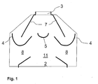
- Figure 1 shows a flow control 1 according to the invention with a lower exhaust manifold 2, which is arranged above a heat exchanger, not shown, of a heater.
- An upper exhaust manifold 7 opens into an exhaust pipe connection 3, from which an exhaust pipe leads into a chimney, not shown.
- a guide 5 centrally below the exhaust pipe connection 3.
- the guide 5 has an approximately semi-cylindrical shape and is arranged symmetrically such that the cylinder axis in the horizontal direction perpendicular to the rear wall 11 of the flow control 1 and is open at the top.
- the flow safety device 1 has lateral openings 6, in each of which deflections 4 are located.
- the deflections 4 have a semicircular contour and are arranged such that the semi-closed semi-circle below the side walls of the upper exhaust manifold 7 is arranged.
- a baffle 10 is arranged, which rises continuously from the middle, lower region upwards and in this case at least approximately adapts to the contour of the guide device 5.
- the baffle 10 is symmetrical and increases to the front wall 12, not shown in this figure, the rear wall 11 opposite as well as the rear wall eleventh
- FIG. 2 shows the baffle 10 isolated.
- FIG. 3 shows the flow safety device 1 diagonally without front wall 12.
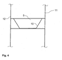
- FIG. 4 shows the guide device 5 with guide plate 10 in section between the front 12 and rear wall 11.
- the fumes can not pass through the fireplace escape, so the exhaust gases flow from the upper exhaust manifold 7 and the deflections 4 in the installation room.
- the baffle 10 within the guide 5 prevents at reflux, that in the edge region exhaust-air mixture presses on the heat exchanger and the combustion chamber and thus hinders the combustion.
Landscapes
- Engineering & Computer Science (AREA)
- Chemical & Material Sciences (AREA)
- Combustion & Propulsion (AREA)
- Mechanical Engineering (AREA)
- General Engineering & Computer Science (AREA)
- Physics & Mathematics (AREA)
- Thermal Sciences (AREA)
- Housings, Intake/Discharge, And Installation Of Fluid Heaters (AREA)
- Details Of Heat-Exchange And Heat-Transfer (AREA)
Abstract
Description
- Die Erfindung bezieht sich auf eine Strömungssicherung für Heizgeräte.
- Bei raumluftabhängigen kamingebundenen Heizgeräten dient eine Strömungssicherung als Zugunterbrechung zwischen Heizgerät und Kamin. Hierdurch können einerseits mehrere Geräte unabhängig voneinander an einem gemeinsamen Kamin betrieben werden; andererseits dient die Strömungssicherung dazu, dass Abgasrückstau oder -rückstrom nicht den Betrieb des Heizgerätes behindert. Kurzfristige Störungen zum Beispiel durch Druckstöße auf den Kamin werden vom Heizgerät weitestgehend entkoppelt und führen somit nicht unmittelbar zum Erlöschen der Flamme.
- Strömungssicherungen für wandhängende Heizgeräte verfügen häufig über Leitvorrichtungen unterhalb des Abgasrohranschlusses, die eine halbzylindrische oder V-Form aufweisen und derart angeordnet sind, dass die Zylinderachse in der Horizontalen senkrecht zur Rückwand verläuft und dabei nach oben offen ist.
- Bei Rückstrom ergibt sich dabei der Effekt, dass der auf die Leitvorrichtung treffende Luftstrahl sowohl zur Seite als auch zur Vorder- und Rückwand abgelenkt wird. In der Mitte der Strömungssicherung wird ein großer Teil der seitlich abgelenkten Luft direkt über die seitlichen Umlenkungen nach außen geleitet. Die zwischen Leitvorrichtung und Umlenkungen nach unten strömenden Luft wird vollständig mit dem aufwärts strömendem Abgas nach außen geführt.
- Im an die Vorder- und Rückwand grenzenden Bereich kann gegebenenfalls ein Teil der sich mit Abgas vermischenden Luft weiter nach unten dringen. An der Hinter- und Vorderwand gelangt das Abgasluftgemisch bis in den Bereich des darunter liegenden Wärmetauschers. Die Abgasrückströmung durch den Wärmetauscher hat einen Einfluss auf den Druck im Brennraum (Flamme) und führt dort lokal zu einer erhöhten Kohlenmonoxidbildung aufgrund von Luftmangel, der aus dem mangelnden Auftrieb resultiert.
- Der Erfindung liegt somit die Aufgabe zugrunde, bei Rückstrom ein ungehindertes Abströmen zu ermöglichen und einen übermäßigen Anstieg der Kohlenmonoxidemissionen zu verhindern.
- Erfindungsgemäß wird dies gemäß den Merkmalen des unabhängigen Anspruchs 1 dadurch erreicht, dass ein Leitblech in der Leitvorrichtung die Strömung optimiert.
- Gemäß den Merkmalen des abhängigen Anspruchs 2 hat das Leitblech einen linearen oder exponentiellen Verlauf.
- Die Erfindung wird nun anhand der Figuren detailliert erläutert. Hierbei zeigen
- Figur 1 eine erfindungsgemäße Strömungssicherung im Schnitt,
- Figur 2 ein erfindungsgemäßes Leitblech,
- Figur 3 eine erfindungsgemäße Strömungssicherung in der diagonalen Ansicht und
- Figur 4 einen Schnitt durch die Leitvorrichtung.
- Figur 1 zeigt eine erfindungsgemäße Strömungssicherung 1 mit einem unteren Abgassammler 2, welcher über einem nicht dargestellten Wärmetauscher eines Heizgerätes angeordnet ist. Ein oberer Abgassammler 7 mündet in einen Abgasrohranschluss 3, von welchem ein Abgasrohr in einen nicht dargestellten Kamin führt. Im oberen Abgassammler 7 befindet sich eine Leitvorrichtung 5 zentral unterhalb des Abgasrohranschlusses 3. Die Leitvorrichtung 5 weist eine annähernd halbzylindrische Form auf und ist derart symmetrisch angeordnet, dass die Zylinderachse in der Horizontalen senkrecht zur Rückwand 11 der Strömungssicherung 1 verläuft und nach oben offen ist. Die Strömungssicherung 1 verfügt über seitliche Öffnungen 6, in denen sich jeweils Umlenkungen 4 befinden. Die Umlenkungen 4 haben eine halbkreisförmige Kontur und sind derart angeordnet, dass der nach unten geschlossene Halbkreis unterhalb der seitlichen Wände des oberen Abgassammlers 7 angeordnet ist. In der Leitvorrichtung 5 ist ein Leitblech 10 angeordnet ist, welches vom mittleren, unteren Bereich kontinuierlich nach oben ansteigt und sich hierbei zumindest annähernd der Kontur der Leitvorrichtung 5 anpasst. Das Leitblech 10 ist symmetrisch und steigt zur in dieser Figur nicht dargestellten, der Rückwand 11 gegenüberliegenden Vorderwand 12 genauso an wie zur Rückwand 11.
- Figur 2 zeigt das Leitblech 10 isoliert. Figur 3 zeigt die Strömungssicherung 1 diagonal ohne Vorderwand 12. Aus Figur 4 geht die Leitvorrichtung 5 mit Leitblech 10 im Schnitt zwischen Vorder- 12 und Rückwand 11 hervor.
- Beim normalen Heizbetrieb durchströmen heiße Abgase den unteren Abgassammler 2. Durch den thermischen Auftrieb strömen die Abgase nach oben, passieren sowohl die Leitvorrichtung 5 als auch die beiden Umlenkungen 4 auf der jeweils dem Aufstellraum abgewandten Seite und verlassen durch den oberen Abgassammler 7 und den Abgasrohranschluss 3 das Heizgerät. Können die Abgase nicht durch den Kamin entweichen, so strömen die Abgase aus dem oberen Abgassammler 7 und die Umlenkungen 4 in den Aufstellraum.
- Das Leitblech 10 innerhalb der Leitvorrichtung 5 verhindert bei Rückstrom, dass im Randbereich Abgas-Luft-Gemisch auf den Wärmetauscher und die Brennkammer drückt und somit die Verbrennung behindert.
Claims (2)
- Strömungssicherung (1) für Heizgeräte, wobei die Strömungssicherung (1) über einen unteren Abgassammler (2), einen oberen Abgassammler (7) mit Abgasrohranschluss (3), eine Leitvorrichtung (5) unterhalb des Abgasrohranschlusses (3), zwei seitliche Öffnungen (6) und mindestens jeweils eine darin befindliche Umlenkung (4) sowie eine Rückwand (11) und eine Vorderwand (12) verfügt, die Leitvorrichtung (5) eine zumindest annähernd halbzylindrische Form aufweist und derart symmetrisch angeordnet ist, dass die Zylinderachse in der Horizontalen senkrecht zur Rückwand (11) verläuft und nach oben offen ist, dadurch gekennzeichnet, dass in der Leitvorrichtung (5) ein Leitblech (10) angeordnet ist, welches vom mittleren, unteren Bereich kontinuierlich nach oben ansteigt und sich hierbei zumindest annähernd der Kontur der Leitvorrichtung (5) anpasst.
- Strömungssicherung (1) für Heizgeräte nach Anspruch 1, dadurch gekennzeichnet, dass das Leitblech linear oder exponentiell ansteigt.
Applications Claiming Priority (1)
| Application Number | Priority Date | Filing Date | Title |
|---|---|---|---|
| AT6662006A AT503133B1 (de) | 2006-04-20 | 2006-04-20 | Strömungssicherung für heizgeräte |
Publications (3)
| Publication Number | Publication Date |
|---|---|
| EP1847787A2 true EP1847787A2 (de) | 2007-10-24 |
| EP1847787A3 EP1847787A3 (de) | 2008-06-11 |
| EP1847787B1 EP1847787B1 (de) | 2015-10-14 |
Family
ID=38222565
Family Applications (1)
| Application Number | Title | Priority Date | Filing Date |
|---|---|---|---|
| EP07007658.3A Not-in-force EP1847787B1 (de) | 2006-04-20 | 2007-04-14 | Strömungssicherung für Heizgeräte |
Country Status (3)
| Country | Link |
|---|---|
| EP (1) | EP1847787B1 (de) |
| AT (1) | AT503133B1 (de) |
| DE (1) | DE102007017721A1 (de) |
Cited By (1)
| Publication number | Priority date | Publication date | Assignee | Title |
|---|---|---|---|---|
| WO2018120151A1 (zh) * | 2016-12-30 | 2018-07-05 | 芜湖美的厨卫电器制造有限公司 | 防风罩和具有其的燃气热水器 |
Citations (1)
| Publication number | Priority date | Publication date | Assignee | Title |
|---|---|---|---|---|
| AT398124B (de) | 1991-05-15 | 1994-09-26 | Vaillant Gmbh | Leiteinrichtung für eine strömungssicherung |
Family Cites Families (6)
| Publication number | Priority date | Publication date | Assignee | Title |
|---|---|---|---|---|
| DE634044C (de) * | 1933-10-29 | 1936-08-14 | Butzke Bernhard Joseph A G F | Rueckstromsicherung fuer gasbeheizte Fluessigkeitserhitzer |
| AT263984B (de) * | 1965-06-22 | 1968-08-12 | Max Ing Loeblich | Mit einem Abgassammler kombinierte Strömungssicherung für Geräte und Anlagen mit Gasfeuerung |
| FR1484208A (fr) * | 1966-06-21 | 1967-06-09 | Dispositif de sécurité d'écoulement combiné à un collecteur de gaz d'échappement et destiné à un foyer à gaz | |
| DE6908327U (de) * | 1969-03-01 | 1969-07-03 | Junkers & Co | Gasbeheizter durchlauf- oder umlauf-wassererhitzer |
| AT387843B (de) * | 1987-02-17 | 1989-03-28 | Vaillant Gmbh | Stroemungssicherung |
| ATA95292A (de) * | 1992-05-11 | 1996-09-15 | Vaillant Gmbh | Strömungssicherung |
-
2006
- 2006-04-20 AT AT6662006A patent/AT503133B1/de not_active IP Right Cessation
-
2007
- 2007-04-14 DE DE200710017721 patent/DE102007017721A1/de not_active Ceased
- 2007-04-14 EP EP07007658.3A patent/EP1847787B1/de not_active Not-in-force
Patent Citations (1)
| Publication number | Priority date | Publication date | Assignee | Title |
|---|---|---|---|---|
| AT398124B (de) | 1991-05-15 | 1994-09-26 | Vaillant Gmbh | Leiteinrichtung für eine strömungssicherung |
Cited By (1)
| Publication number | Priority date | Publication date | Assignee | Title |
|---|---|---|---|---|
| WO2018120151A1 (zh) * | 2016-12-30 | 2018-07-05 | 芜湖美的厨卫电器制造有限公司 | 防风罩和具有其的燃气热水器 |
Also Published As
| Publication number | Publication date |
|---|---|
| AT503133A4 (de) | 2007-08-15 |
| EP1847787A3 (de) | 2008-06-11 |
| DE102007017721A1 (de) | 2007-10-25 |
| AT503133B1 (de) | 2007-08-15 |
| EP1847787B1 (de) | 2015-10-14 |
Similar Documents
| Publication | Publication Date | Title |
|---|---|---|
| EP1847787B1 (de) | Strömungssicherung für Heizgeräte | |
| DE3308700C2 (de) | Einrichtung zum Heizen und Lüften | |
| EP0042129B1 (de) | Abgaswärmetauscher | |
| DE3024199C2 (de) | Gaswarngerät | |
| DE202021100257U1 (de) | Einzelraumfeuerstätte mit einem Katalysator | |
| EP0936409B1 (de) | Abgasführung für ein Heizgerät | |
| DE8520263U1 (de) | Durchlauf- oder Speicherwasserheizer | |
| EP0123869B1 (de) | Brennwertkessel, insbesondere zur Erzeugung von Heiss- oder Heizwasser mit einem Gasbrenner | |
| DE3430415C2 (de) | ||
| EP1241408B1 (de) | Brenner für ein Brennstoffgemisch aus Luft und Gas | |
| EP1939530B1 (de) | Zusatzeinrichtung für Kaminöfen | |
| EP3892919B1 (de) | Heizgerät für ein gebäude, umfassend ein system mit einer strömungsführungseinrichtung zur führung mindestens einer fluid-strömung im bereich einer fördereinrichtung des heizgeräts | |
| DE102014103447A1 (de) | Heizungsanlage | |
| CH657912A5 (de) | Gasbeheizte kesselanlage. | |
| DE9407914U1 (de) | Gußgliederkessel | |
| DE365718C (de) | Geraet fuer Tischlereizwecke | |
| DE77399C (de) | Flammofen mit darunter befindlichem Recuperatorsystem | |
| DE29505196U1 (de) | Heizgerät | |
| AT411102B (de) | Brennwert-heizgerät | |
| DE19744013A1 (de) | Anordnung von mehreren Gas-Brennwert-Feuerstätten | |
| AT505134B1 (de) | Vorrichtung zur vermeidung selbsterregter verbrennungsschwingungen | |
| AT263984B (de) | Mit einem Abgassammler kombinierte Strömungssicherung für Geräte und Anlagen mit Gasfeuerung | |
| DE102019217701A1 (de) | Brennervorrichtung | |
| DD149882A3 (de) | Abgassystem fuer raumheizgeraete | |
| DE2433387A1 (de) | Brenneinrichtung an brennraeumen von kesseln oder dergleichen |
Legal Events
| Date | Code | Title | Description |
|---|---|---|---|
| PUAI | Public reference made under article 153(3) epc to a published international application that has entered the european phase |
Free format text: ORIGINAL CODE: 0009012 |
|
| AK | Designated contracting states |
Kind code of ref document: A2 Designated state(s): AT BE BG CH CY CZ DE DK EE ES FI FR GB GR HU IE IS IT LI LT LU LV MC MT NL PL PT RO SE SI SK TR |
|
| AX | Request for extension of the european patent |
Extension state: AL BA HR MK YU |
|
| PUAL | Search report despatched |
Free format text: ORIGINAL CODE: 0009013 |
|
| AK | Designated contracting states |
Kind code of ref document: A3 Designated state(s): AT BE BG CH CY CZ DE DK EE ES FI FR GB GR HU IE IS IT LI LT LU LV MC MT NL PL PT RO SE SI SK TR |
|
| AX | Request for extension of the european patent |
Extension state: AL BA HR MK RS |
|
| RIC1 | Information provided on ipc code assigned before grant |
Ipc: F24H 9/00 20060101AFI20070716BHEP Ipc: F23M 9/00 20060101ALI20080505BHEP Ipc: F24H 9/20 20060101ALI20080505BHEP |
|
| 17P | Request for examination filed |
Effective date: 20081028 |
|
| AKX | Designation fees paid |
Designated state(s): AT BE BG CH CY CZ DE DK EE ES FI FR GB GR HU IE IS IT LI LT LU LV MC MT NL PL PT RO SE SI SK TR |
|
| GRAP | Despatch of communication of intention to grant a patent |
Free format text: ORIGINAL CODE: EPIDOSNIGR1 |
|
| INTG | Intention to grant announced |
Effective date: 20150515 |
|
| GRAS | Grant fee paid |
Free format text: ORIGINAL CODE: EPIDOSNIGR3 |
|
| GRAA | (expected) grant |
Free format text: ORIGINAL CODE: 0009210 |
|
| AK | Designated contracting states |
Kind code of ref document: B1 Designated state(s): AT BE BG CH CY CZ DE DK EE ES FI FR GB GR HU IE IS IT LI LT LU LV MC MT NL PL PT RO SE SI SK TR |
|
| REG | Reference to a national code |
Ref country code: GB Ref legal event code: FG4D Free format text: NOT ENGLISH |
|
| REG | Reference to a national code |
Ref country code: AT Ref legal event code: REF Ref document number: 755448 Country of ref document: AT Kind code of ref document: T Effective date: 20151015 Ref country code: CH Ref legal event code: EP |
|
| REG | Reference to a national code |
Ref country code: IE Ref legal event code: FG4D Free format text: LANGUAGE OF EP DOCUMENT: GERMAN |
|
| REG | Reference to a national code |
Ref country code: DE Ref legal event code: R096 Ref document number: 502007014298 Country of ref document: DE |
|
| REG | Reference to a national code |
Ref country code: NL Ref legal event code: MP Effective date: 20151014 |
|
| REG | Reference to a national code |
Ref country code: LT Ref legal event code: MG4D |
|
| REG | Reference to a national code |
Ref country code: FR Ref legal event code: PLFP Year of fee payment: 10 |
|
| PG25 | Lapsed in a contracting state [announced via postgrant information from national office to epo] |
Ref country code: IS Free format text: LAPSE BECAUSE OF FAILURE TO SUBMIT A TRANSLATION OF THE DESCRIPTION OR TO PAY THE FEE WITHIN THE PRESCRIBED TIME-LIMIT Effective date: 20160214 Ref country code: NL Free format text: LAPSE BECAUSE OF FAILURE TO SUBMIT A TRANSLATION OF THE DESCRIPTION OR TO PAY THE FEE WITHIN THE PRESCRIBED TIME-LIMIT Effective date: 20151014 Ref country code: IT Free format text: LAPSE BECAUSE OF FAILURE TO SUBMIT A TRANSLATION OF THE DESCRIPTION OR TO PAY THE FEE WITHIN THE PRESCRIBED TIME-LIMIT Effective date: 20151014 Ref country code: ES Free format text: LAPSE BECAUSE OF FAILURE TO SUBMIT A TRANSLATION OF THE DESCRIPTION OR TO PAY THE FEE WITHIN THE PRESCRIBED TIME-LIMIT Effective date: 20151014 Ref country code: LT Free format text: LAPSE BECAUSE OF FAILURE TO SUBMIT A TRANSLATION OF THE DESCRIPTION OR TO PAY THE FEE WITHIN THE PRESCRIBED TIME-LIMIT Effective date: 20151014 |
|
| PG25 | Lapsed in a contracting state [announced via postgrant information from national office to epo] |
Ref country code: PL Free format text: LAPSE BECAUSE OF FAILURE TO SUBMIT A TRANSLATION OF THE DESCRIPTION OR TO PAY THE FEE WITHIN THE PRESCRIBED TIME-LIMIT Effective date: 20151014 Ref country code: SE Free format text: LAPSE BECAUSE OF FAILURE TO SUBMIT A TRANSLATION OF THE DESCRIPTION OR TO PAY THE FEE WITHIN THE PRESCRIBED TIME-LIMIT Effective date: 20151014 Ref country code: FI Free format text: LAPSE BECAUSE OF FAILURE TO SUBMIT A TRANSLATION OF THE DESCRIPTION OR TO PAY THE FEE WITHIN THE PRESCRIBED TIME-LIMIT Effective date: 20151014 Ref country code: LV Free format text: LAPSE BECAUSE OF FAILURE TO SUBMIT A TRANSLATION OF THE DESCRIPTION OR TO PAY THE FEE WITHIN THE PRESCRIBED TIME-LIMIT Effective date: 20151014 Ref country code: PT Free format text: LAPSE BECAUSE OF FAILURE TO SUBMIT A TRANSLATION OF THE DESCRIPTION OR TO PAY THE FEE WITHIN THE PRESCRIBED TIME-LIMIT Effective date: 20160215 Ref country code: GR Free format text: LAPSE BECAUSE OF FAILURE TO SUBMIT A TRANSLATION OF THE DESCRIPTION OR TO PAY THE FEE WITHIN THE PRESCRIBED TIME-LIMIT Effective date: 20160115 |
|
| REG | Reference to a national code |
Ref country code: DE Ref legal event code: R097 Ref document number: 502007014298 Country of ref document: DE |
|
| PG25 | Lapsed in a contracting state [announced via postgrant information from national office to epo] |
Ref country code: CZ Free format text: LAPSE BECAUSE OF FAILURE TO SUBMIT A TRANSLATION OF THE DESCRIPTION OR TO PAY THE FEE WITHIN THE PRESCRIBED TIME-LIMIT Effective date: 20151014 |
|
| PLBE | No opposition filed within time limit |
Free format text: ORIGINAL CODE: 0009261 |
|
| STAA | Information on the status of an ep patent application or granted ep patent |
Free format text: STATUS: NO OPPOSITION FILED WITHIN TIME LIMIT |
|
| PG25 | Lapsed in a contracting state [announced via postgrant information from national office to epo] |
Ref country code: SK Free format text: LAPSE BECAUSE OF FAILURE TO SUBMIT A TRANSLATION OF THE DESCRIPTION OR TO PAY THE FEE WITHIN THE PRESCRIBED TIME-LIMIT Effective date: 20151014 Ref country code: BE Free format text: LAPSE BECAUSE OF NON-PAYMENT OF DUE FEES Effective date: 20160430 Ref country code: EE Free format text: LAPSE BECAUSE OF FAILURE TO SUBMIT A TRANSLATION OF THE DESCRIPTION OR TO PAY THE FEE WITHIN THE PRESCRIBED TIME-LIMIT Effective date: 20151014 Ref country code: DK Free format text: LAPSE BECAUSE OF FAILURE TO SUBMIT A TRANSLATION OF THE DESCRIPTION OR TO PAY THE FEE WITHIN THE PRESCRIBED TIME-LIMIT Effective date: 20151014 Ref country code: RO Free format text: LAPSE BECAUSE OF FAILURE TO SUBMIT A TRANSLATION OF THE DESCRIPTION OR TO PAY THE FEE WITHIN THE PRESCRIBED TIME-LIMIT Effective date: 20151014 |
|
| 26N | No opposition filed |
Effective date: 20160715 |
|
| REG | Reference to a national code |
Ref country code: DE Ref legal event code: R119 Ref document number: 502007014298 Country of ref document: DE |
|
| PG25 | Lapsed in a contracting state [announced via postgrant information from national office to epo] |
Ref country code: SI Free format text: LAPSE BECAUSE OF FAILURE TO SUBMIT A TRANSLATION OF THE DESCRIPTION OR TO PAY THE FEE WITHIN THE PRESCRIBED TIME-LIMIT Effective date: 20151014 |
|
| REG | Reference to a national code |
Ref country code: CH Ref legal event code: PL |
|
| GBPC | Gb: european patent ceased through non-payment of renewal fee |
Effective date: 20160414 |
|
| PG25 | Lapsed in a contracting state [announced via postgrant information from national office to epo] |
Ref country code: LU Free format text: LAPSE BECAUSE OF FAILURE TO SUBMIT A TRANSLATION OF THE DESCRIPTION OR TO PAY THE FEE WITHIN THE PRESCRIBED TIME-LIMIT Effective date: 20160414 |
|
| REG | Reference to a national code |
Ref country code: IE Ref legal event code: MM4A |
|
| PG25 | Lapsed in a contracting state [announced via postgrant information from national office to epo] |
Ref country code: CH Free format text: LAPSE BECAUSE OF NON-PAYMENT OF DUE FEES Effective date: 20160430 Ref country code: GB Free format text: LAPSE BECAUSE OF NON-PAYMENT OF DUE FEES Effective date: 20160414 Ref country code: LI Free format text: LAPSE BECAUSE OF NON-PAYMENT OF DUE FEES Effective date: 20160430 Ref country code: DE Free format text: LAPSE BECAUSE OF NON-PAYMENT OF DUE FEES Effective date: 20161101 |
|
| REG | Reference to a national code |
Ref country code: FR Ref legal event code: PLFP Year of fee payment: 11 |
|
| PG25 | Lapsed in a contracting state [announced via postgrant information from national office to epo] |
Ref country code: IE Free format text: LAPSE BECAUSE OF NON-PAYMENT OF DUE FEES Effective date: 20160414 |
|
| REG | Reference to a national code |
Ref country code: AT Ref legal event code: MM01 Ref document number: 755448 Country of ref document: AT Kind code of ref document: T Effective date: 20160414 |
|
| PG25 | Lapsed in a contracting state [announced via postgrant information from national office to epo] |
Ref country code: AT Free format text: LAPSE BECAUSE OF NON-PAYMENT OF DUE FEES Effective date: 20160414 |
|
| REG | Reference to a national code |
Ref country code: FR Ref legal event code: PLFP Year of fee payment: 12 |
|
| PG25 | Lapsed in a contracting state [announced via postgrant information from national office to epo] |
Ref country code: CY Free format text: LAPSE BECAUSE OF FAILURE TO SUBMIT A TRANSLATION OF THE DESCRIPTION OR TO PAY THE FEE WITHIN THE PRESCRIBED TIME-LIMIT Effective date: 20151014 Ref country code: HU Free format text: LAPSE BECAUSE OF FAILURE TO SUBMIT A TRANSLATION OF THE DESCRIPTION OR TO PAY THE FEE WITHIN THE PRESCRIBED TIME-LIMIT; INVALID AB INITIO Effective date: 20070414 |
|
| PG25 | Lapsed in a contracting state [announced via postgrant information from national office to epo] |
Ref country code: MC Free format text: LAPSE BECAUSE OF FAILURE TO SUBMIT A TRANSLATION OF THE DESCRIPTION OR TO PAY THE FEE WITHIN THE PRESCRIBED TIME-LIMIT Effective date: 20151014 Ref country code: MT Free format text: LAPSE BECAUSE OF FAILURE TO SUBMIT A TRANSLATION OF THE DESCRIPTION OR TO PAY THE FEE WITHIN THE PRESCRIBED TIME-LIMIT Effective date: 20151014 |
|
| PG25 | Lapsed in a contracting state [announced via postgrant information from national office to epo] |
Ref country code: BG Free format text: LAPSE BECAUSE OF FAILURE TO SUBMIT A TRANSLATION OF THE DESCRIPTION OR TO PAY THE FEE WITHIN THE PRESCRIBED TIME-LIMIT Effective date: 20151014 |
|
| PGFP | Annual fee paid to national office [announced via postgrant information from national office to epo] |
Ref country code: TR Payment date: 20200325 Year of fee payment: 14 |
|
| PGFP | Annual fee paid to national office [announced via postgrant information from national office to epo] |
Ref country code: FR Payment date: 20200420 Year of fee payment: 14 |
|
| PG25 | Lapsed in a contracting state [announced via postgrant information from national office to epo] |
Ref country code: FR Free format text: LAPSE BECAUSE OF NON-PAYMENT OF DUE FEES Effective date: 20210430 |
|
| PG25 | Lapsed in a contracting state [announced via postgrant information from national office to epo] |
Ref country code: TR Free format text: LAPSE BECAUSE OF NON-PAYMENT OF DUE FEES Effective date: 20210414 |