EP1847729A2 - Ausfahrbare Säule - Google Patents
Ausfahrbare Säule Download PDFInfo
- Publication number
- EP1847729A2 EP1847729A2 EP07007486A EP07007486A EP1847729A2 EP 1847729 A2 EP1847729 A2 EP 1847729A2 EP 07007486 A EP07007486 A EP 07007486A EP 07007486 A EP07007486 A EP 07007486A EP 1847729 A2 EP1847729 A2 EP 1847729A2
- Authority
- EP
- European Patent Office
- Prior art keywords
- column
- bands
- base
- intermediate elements
- drive
- Prior art date
- Legal status (The legal status is an assumption and is not a legal conclusion. Google has not performed a legal analysis and makes no representation as to the accuracy of the status listed.)
- Granted
Links
Images

Classifications
-
- F—MECHANICAL ENGINEERING; LIGHTING; HEATING; WEAPONS; BLASTING
- F16—ENGINEERING ELEMENTS AND UNITS; GENERAL MEASURES FOR PRODUCING AND MAINTAINING EFFECTIVE FUNCTIONING OF MACHINES OR INSTALLATIONS; THERMAL INSULATION IN GENERAL
- F16H—GEARING
- F16H25/00—Gearings comprising primarily only cams, cam-followers and screw-and-nut mechanisms
- F16H25/18—Gearings comprising primarily only cams, cam-followers and screw-and-nut mechanisms for conveying or interconverting oscillating or reciprocating motions
- F16H25/20—Screw mechanisms
- F16H25/24—Elements essential to such mechanisms, e.g. screws, nuts
- F16H25/2409—Elements essential to such mechanisms, e.g. screws, nuts one of the threads being replaced by elements specially formed for engaging the screw or nut, e.g. pins, racks, toothed belts
-
- F—MECHANICAL ENGINEERING; LIGHTING; HEATING; WEAPONS; BLASTING
- F16—ENGINEERING ELEMENTS AND UNITS; GENERAL MEASURES FOR PRODUCING AND MAINTAINING EFFECTIVE FUNCTIONING OF MACHINES OR INSTALLATIONS; THERMAL INSULATION IN GENERAL
- F16H—GEARING
- F16H19/00—Gearings comprising essentially only toothed gears or friction members and not capable of conveying indefinitely-continuing rotary motion
- F16H19/02—Gearings comprising essentially only toothed gears or friction members and not capable of conveying indefinitely-continuing rotary motion for interconverting rotary or oscillating motion and reciprocating motion
- F16H19/06—Gearings comprising essentially only toothed gears or friction members and not capable of conveying indefinitely-continuing rotary motion for interconverting rotary or oscillating motion and reciprocating motion comprising flexible members, e.g. an endless flexible member
- F16H19/0636—Gearings comprising essentially only toothed gears or friction members and not capable of conveying indefinitely-continuing rotary motion for interconverting rotary or oscillating motion and reciprocating motion comprising flexible members, e.g. an endless flexible member the flexible member being a non-buckling chain
-
- F—MECHANICAL ENGINEERING; LIGHTING; HEATING; WEAPONS; BLASTING
- F16—ENGINEERING ELEMENTS AND UNITS; GENERAL MEASURES FOR PRODUCING AND MAINTAINING EFFECTIVE FUNCTIONING OF MACHINES OR INSTALLATIONS; THERMAL INSULATION IN GENERAL
- F16H—GEARING
- F16H19/00—Gearings comprising essentially only toothed gears or friction members and not capable of conveying indefinitely-continuing rotary motion
- F16H19/02—Gearings comprising essentially only toothed gears or friction members and not capable of conveying indefinitely-continuing rotary motion for interconverting rotary or oscillating motion and reciprocating motion
- F16H19/06—Gearings comprising essentially only toothed gears or friction members and not capable of conveying indefinitely-continuing rotary motion for interconverting rotary or oscillating motion and reciprocating motion comprising flexible members, e.g. an endless flexible member
- F16H19/0645—Gearings comprising essentially only toothed gears or friction members and not capable of conveying indefinitely-continuing rotary motion for interconverting rotary or oscillating motion and reciprocating motion comprising flexible members, e.g. an endless flexible member the flexible push or pull member having guiding means, i.e. the flexible member being supported at least partially by a guide to transmit the reciprocating movement
Definitions
- the invention relates to an extendable column with a base, an extendable from the base column shaft, a head and a drive.
- Such extendable columns depending on their nature and use and linear drives, spindles, stamp or the like. are commonly used to objects, assemblies or machine parts movable, in particular height adjustable, to wear or move.
- mechanical spindles such as screw spindles or racks, as well as hydraulic punches or cylinder units
- there is a problem that the unit even when fully retracted has a large footprint, which usually accounts for more than half of the extended total length as a dead space. Although this can be reduced with multiple telescopic units, but requires a lot of effort.
- the object of the invention is to provide an extendable column that requires only small axial dimensions in the retracted state.
- the column shaft has a plurality of flexible bands distributed over the circumference of the column shaft and cambered in the column region.
- the tapes can roll themselves up or be rolled up in the area of the base and take up so little axial space.
- the rolled-up tape reels then lie in the base area outside next to the base and take up no axial space. But it would also be possible to run through radially outgoing from the base guides the straps straight, where they would occupy even less height, but a greater width.
- the bands can be guided by guides in the base so that they are transferred from their outer rolled-up position in the substantially rectilinear, parallel to the column axis extending position in which they are cambered self-stiffening. In this case, the crowning outward, so that results from the numerous, for example, six bands arranged around the column shaft around a nearly circular column shaft cross section.
- the bands are connected together in the column shaft area by intermediate elements, in which they engage with their edge regions.
- These intermediate elements may for example consist of individual members which form a pressure-resistant and preferably also tensile, but at least in one direction flexible chain-like strand.
- the individual members can thus have grooves or slots on both sides, into which the edges of the bands engage.
- Particularly preferred is an embodiment in which the links inside tooth-like projections which are driven by a drive gear, for example, a concentric to the column screw or screw in the direction of the column axis.
- this strand of limbs has a multiple task, namely on the one hand to produce a pressure-resistant connection and thus to ensure the actual support function of the column, on the other hand, the bands that are responsible for the stiffening against buckling, connect and lead and drive to enable.
- the flexible strand can also be deflected in the base by guides to the outside, so that he needs no additional height.
- the column can be made tensile by allowing the individual members of the strand, e.g. By inside running steel wire ropes, are joined together to form a tensile strand.
- an extendable column which can be used as a linear drive, as a support element or the like.
- this column may have an extended height of more than ten times the minimum height.
- Theoretically, the maximum extension height or length is unlimited, as long as the static conditions are met. It is thus created an ideal component for lifting platforms, etc., without making demands on a substructure.
- the drive can be done for example via a geared motor in the manner of a truck windscreen wiper motor, but also via a toothed belt drive, wherein the motor can be arranged laterally from the base and thus does not affect the overall height.
- a drive could also be effected via pinions, which are arranged inside in star shape. It is also not absolutely necessary to design all intermediate elements as drive elements. So it could be some, for example, two opposing elements, interact with drive pinions, while the remaining intermediate elements are designed only for connecting the bands. Also, external engagement of the drive, e.g. in the base area by pinion, is possible. Further, it would be conceivable to make the drive not via intermediate elements, but directly on the bands by these corresponding engagement elements receive, for example, a longitudinal perforation, engage in the drive pinion.
- the intermediate elements increase the rigidity of the forming column by their banding effect. However, the bands already have a great inherent rigidity, so that it would also be possible to completely omit the intermediate elements and to form the column exclusively from the cambered bands.
- a self-assembling column which can be used as a linear drive, lifting ram or the like, has a base and a head.
- the intermediate retractable column shaft is composed of flexible steel bands cambered around the perimeter of the column shaft, which are cambered in the columnar area, extending outside this stretched area, i. Roll up automatically next to the pedestal.
- Interposed between the bands is a strand of individual links, which receives the edges of the bands in the area of the column shaft, which connects bands and at the same time provides the linear drive, by providing toothing on the strand with a screw mounted concentrically in the column according to Art a thread cooperate. It thus creates a pillar, which assembles itself and requires almost no dead space.
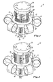
- the drawings show an extendable column 11 which can be used as a linear drive, a length-adjustable support column or the like. It has a base 12, e.g. can be supported on a floor or machine part, an extendable from the base and thus variable in length column shaft 13 and the column shaft limiting column head 14th
- the base is circular in its basic form with a base portion 15 and a collar 16 surrounding the lower part of the column shaft 13.
- guides 17, 18 are provided which are curved or obliquely outwardly from the column shaft.
- a cambered belt 20 is guided, which rolls up outside of the base itself as a roller 21. Overall, in the example shown, six such bands are present on the circumference.
- the bands are made of a high strength, flexible material, such as spring steel, which is tensioned by a crowning so that when stretched, it receives a camber or bulge transverse to the longitudinal direction of the band that stiffens the band in the stretched condition and thus the transfer right allows considerable pressure forces without buckling. However, if it is bent, for example by partial impressions of the crowning, it rolls automatically to the role 21.
- Such bands can be obtained, for example, from COBRA Bandstahl GmbH, Wambatersbach.
- the total of six bands are attached with their ends to the head 14, so that they, with their crowning in each case outwardly facing, evenly around the circumference of the column shaft 13 are arranged and then run from the column shaft in the guide 17 of the base, where they inside the guide undergo a reversible buckling, so that they then run out of the guide 17 on the circumference of the base and there form the roll or the winding 21.
- the intermediate elements 22 consist of a strand of individual members, which are shown in detail in Figures 5 and 6.
- the existing metal or plastic members 23 have on both sides each have a surface 24, with which they are supported against each other. This surface may be slightly curved to allow it to roll when bending the strand. Slots or grooves 25 with insertion bevels are provided on both sides, into which the side edges of the bands 20 can engage (indicated by dashed lines in FIG. 5).
- drive elements 26 are provided which protrude in the manner of teeth inwardly and are so much narrower than the dimension of the member in the direction of the column axis 27, that in between threads with flanks 35 of a central screw or worm 27, the one Drive element for the extension movement forms, can intervene.
- This drive engagement occurs in the area surrounded by the collar 16, so that the intermediate elements 22 can be supported thereon.
- the members 23 further have in the illustrated example, two openings 28, a stringing of the links to form a closed, the intermediate element forming strand 22 by means of two in the example Wire ropes 29 allows. These are in the head, for example, by a thickened end 30, fixed and braced at the other end of the strand. On the outwardly facing side of the member a groove 31 is likewise provided, which serves for guiding and pressing the flexible intermediate elements by a bow spring 32 in the region of the guides 18.
- the members thus form a pressure and tensile closed strand, but so far is flexible that it can be deflected in the region of the guide 18 to the outside and finally also completely in a radial direction to the column axis 27.
- the guide 18 is designed so that it introduces the strand on the one hand in the thread of the screw 27, while on the other hand, the edges of the bands 20 laterally enter into the grooves 25. This is possible because the respectively approximately radial combination of the intermediate element strands 22 and the bands 20 an angle enabling the introduction is formed.
- the drive element forming screw 27 has a diameter corresponding to the column shaft inner diameter. It is rotatably mounted in a central recess of the base about the column axis 27 and is rotatably driven by an indicated motor 33.
- the head 14 When the column is retracted, ie moved to the lowest possible axial height, the head 14 rests on the base 12.
- the bands 20 are rolled up as far as possible and the intermediate elements 22 may be compared to the position shown in Fig. 3 further out in the horizontal. It is also possible for them to provide a lateral, radially away from the base leading exit, for example, by an additional kink or a rounding in the guide 18th
- the screw 27 is rotated by the motor 23, possibly via a gear, so that the thread flanks 35 engage with the projections 26 and move the intermediate element strand upwards. This can not buckle, since its grooves 25 are in engagement with the bands 20.
- the screw or worm 27 thus works together with the total of six intermediate elements on the circumference such as screw and nut. This drive is usually self-locking, so that no drive brake is necessary for the support function of the column.
- the bands 20 drawn in by the guides 17 thread into the grooves 25 of the intermediate element members 23, so that a closed contiguous column shaft is formed.
- This is circular in the example shown and consists of six bands and six intermediate elements.
- it is also possible to produce other columnar shapes, although the curvature predetermined by the crowning of the bands is also advantageous as a segment for the columnar cross-section. But it can also deviating shapes, possibly even be generated with inwardly cambered bands and accordingly inside running roles.
- the tape When ascending the column shaft, the tape is stretched in each case by the guide 17 in the base and thereby assumes its cambered shape. Inwardly directed domed projections 37 in the recess 38 of the socket guide the tape with a line contact.
- the tension of the intermediate element strand 22 by the tension elements creates a tensile and transverse relatively kink resistant strand, but without hindering the flexibility in the direction resulting from the drawings direction.
- a flange 36 is provided, via which the modules moved and supported with the column can be connected.
- the screw When retracting the column, the screw is rotated in the opposite direction, pulls the intermediate element strands 22 evenly down, which is not precisely possible by the tension-resistant connection.
- the belts automatically roll up again and the intermediate element strands 22 are pushed out laterally. In this case, the impressions of the crowning of the band 20 for winding is supported by the projections 37.
- the intermediate element strands rather than individual elements, also as a continuous band using e.g.
- the individual links are connected to each other via film hinges, which can be sufficient for low stress.
- the bands are preferably made of high strength spring steel and are only a few tenths of a millimeter thick. However, for certain requirements they could also consist of other materials which have the appropriate strength and a modulus of elasticity, for example made of carbon fiber reinforced plastic.
Landscapes
- General Engineering & Computer Science (AREA)
- Engineering & Computer Science (AREA)
- Mechanical Engineering (AREA)
- Transmission Devices (AREA)
- Forms Removed On Construction Sites Or Auxiliary Members Thereof (AREA)
- Accommodation For Nursing Or Treatment Tables (AREA)
- Supports For Plants (AREA)
- Hydrogenated Pyridines (AREA)
- Polyoxymethylene Polymers And Polymers With Carbon-To-Carbon Bonds (AREA)
- Orthopedics, Nursing, And Contraception (AREA)
- Conveying And Assembling Of Building Elements In Situ (AREA)
- Lock And Its Accessories (AREA)
- Automotive Seat Belt Assembly (AREA)
Abstract
Description
- Die Erfindung betrifft eine ausfahrbare Säule mit einem Sockel, einem aus dem Sockel ausfahrbaren Säulenschaft, einem Kopf und einem Antrieb. Derartige ausfahrbare Säulen, die je nach ihrer Art und Verwendung auch Linearantriebe, Spindeln, Stempel odgl. genannt werden, dienen normalerweise dazu, Gegenstände, Baugruppen oder Maschinenteile verfahrbar, insbesondere höhenverstellbar, zu tragen oder zu bewegen. Im Falle von mechanischen Spindeln, beispielsweise Schraubspindeln oder Zahnstangen, ebenso wie bei hydraulischen Stempeln oder Zylindereinheiten, besteht ein Problem darin, dass die Einheit auch in ganz eingefahrenem Zustand einen großen Platzbedarf hat, der als Totraum meist mehr als die Hälfte der ausgefahrenen Gesamtlänge ausmacht. Dies kann zwar mit mehrfach teleskopischen Einheiten verringert werden, erfordert jedoch einen großen Aufwand.
- Es sind sogenannte Schubkettenantriebe bekannt geworden, die aus einzelnen Kettengliedern bestehen, die sich einander versteifend zu einer Stange zusammenfügen. Diese Antriebe sind allerdings nicht zugfest und nicht völlig sicher gegen Ausknicken.
- Es sind Stahlbänder bekannt, die im gestreckten Zustand bombiert, d.h. in Querrichtung gewölbt sind und sich beim Ausknicken selbsttätig aufrollen, wobei sie dann als gerader, unbombierter Wickel vorliegen. Derartige Stahlbänder sind beispielsweise als Rollbandmaße bekannt. Es sind auch schon Getriebe damit vorgeschlagen worden, z.B. in der
EP 363 939 B1 deutschen Patentschrift DE 38 38 724 C2 . Sie haben sich in der Praxis, zum Teil aus Verschleißgründen, nicht durchgesetzt. - Aufgabe der Erfindung ist es, eine ausfahrbare Säule zu schaffen, die im eingefahrenen Zustand nur geringe axiale Abmessungen benötigt.
- Gelöst wird diese Aufgabe durch eine Säule mit den Merkmalen des Anspruchs 1. Vorteilhafte sowie bevorzugte Ausgestaltungen der Erfindung sind Gegenstand der weiteren Ansprüche und werden im Folgenden näher erläutert. Der Wortlaut der Ansprüche wird durch ausdrückliche Bezugnahme zum Inhalt der Beschreibung gemacht.
- Erfindungsgemäß weist der Säulenschaft mehrere über den Umfang des Säulenschaftes verteilte flexible, im Säulenbereich bombierte Bänder auf. Die Bänder können sich im Bereich des Sockels selbst aufrollen bzw. aufgerollt werden und nehmen so wenig axialen Raum ein. Die aufgerollten Bandwickel liegen dann im Sockelbereich außen neben dem Sockel und nehmen keinen axialen Platz ein. Es wäre aber auch möglich, durch radial vom Sockel ausgehende Führungen die Bänder gerade zu führen, wobei sie noch weniger Höhe, dafür aber eine größere Breite einnehmen würden.
- Die Bänder können durch Führungen im Sockel so geführt werden, dass sie von ihrer äußeren aufgerollten Lage in die im wesentlichen geradlinige, parallel zur Säulenachse verlaufende Lage überführt werden, in der sie selbstversteifend bombiert sind. Dabei weist die Bombierung nach außen, so dass sich aus den zahlreichen, beispielsweise sechs um den Säulenschaft herum angeordneten Bändern ein nahezu kreisförmiger Säulenschaftquerschnitt ergibt.
- Die Bänder sind im Säulenschaftbereich durch Zwischenelemente miteinander verbunden, in die sie mit ihren Randbereichen eingreifen. Diese Zwischenelemente können beispielsweise aus einzelnen Gliedern bestehen, die einen druck- und vorzugsweise auch zugfesten, jedoch zumindest in einer Richtung flexiblen kettenartigen Strang bilden. Die einzelnen Glieder können also auf beiden Seiten Nuten oder Schlitze haben, in die die Ränder der Bänder eingreifen. Besonders bevorzugt ist eine Ausführung, in der die Glieder innen zahnartige Vorsprünge aufweisen, die von einem Antriebsgetriebe, beispielsweise einer zur Säule konzentrischen Schnecke oder Schraube, in Richtung der Säulenachse angetrieben werden. Dieser Strang aus den Gliedern hat also eine mehrfache Aufgabe, nämlich einerseits eine druckfeste Verbindung herzustellen und somit die eigentliche Tragfunktion der Säule zu gewährleisten, andererseits die Bänder, die für die Versteifung gegen Ausknicken zuständig sind, miteinander zu verbinden und zu führen und den Antrieb zu ermöglichen. Der flexible Strang kann ebenfalls im Sockel durch Führungen nach außen abgelenkt werden, so dass er auch keine zusätzliche Höhe benötigt. Die Säule kann dadurch zugfest gemacht werden, dass die einzelnen Glieder des Stranges, z.B. durch innen laufende Stahldrahtseile, miteinander zu einem zugfesten Strang zusammengefügt sind.
- Es ergibt sich somit eine ausfahrbare Säule, die als Linearantrieb, als Tragelement oder dgl. verwendet werden kann. Bei einer Minimalhöhe, die fast auf die Höhe des Sockels beschränkt ist, von nur wenigen Zentimetern, kann diese Säule eine ausgefahrene Höhe von mehr als dem Zehnfachen der Minimalhöhe haben. Theoretisch ist die maximale Ausfahrhöhe bzw. -länge unbegrenzt, solange die statischen Voraussetzungen gegeben sind. Es wird somit ein ideales Bauelement für Hebebühnen etc. geschaffen, ohne es Anforderungen an einen Unterbau stellt. Der Antrieb kann beispielsweise über einen Getriebemotor nach Art eines LKW-Scheibenwischenmotors, jedoch auch über einen Zahnriemenantrieb erfolgen, wobei der Motor seitlich vom Sockel angeordnet sein kann und somit die Bauhöhe nicht beeinträchtigt.
- Im Rahmen der Erfindung sind zahlreiche Abwandlungen von der beschriebenen bevorzugten Ausführung möglich. So könnte statt eines den Innenraum der Säule füllenden Schrauben- bzw. Schneckenantriebs auch ein Antrieb über Ritzel erfolgen, die innen in Sternform angeordnet sind. Es ist auch nicht zwingend notwendig, sämtliche Zwischenelemente als Antriebselemente auszubilden. Es könnten also einige, beispielsweise zwei gegenüber liegende Elemente, mit Antriebsritzeln zusammenwirken, während die übrigen Zwischenelemente nur zur Verbindung der Bänder ausgebildet sind. Auch ein Eingriff des Antriebs von außen, z.B. im Sockelbereich durch Ritzel, ist möglich. Ferner wäre es denkbar, den Antrieb nicht über Zwischenelemente, sondern direkt über die Bänder vorzunehmen, indem diese entsprechende Angriffselemente erhalten, beispielsweise eine Längsperforation, in die Antriebsritzel eingreifen. Die Zwischenelemente erhöhen durch ihre die Bänder verbindende Wirkung die Steifigkeit der sich bildenden Säule. Allerdings haben die Bänder auch schon eine große Eigensteifigkeit, so dass es auch möglich wäre, die Zwischenelemente ganz weg zu lassen und die Säule ausschließlich aus den bombierten Bändern zu bilden.
- Es ist auch möglich, die Säule mit einem nur in eine Richtung aktiv verstellbaren Antrieb auszustatten. So könnte beispielsweise durch eine innen liegende vorgespannte Schraubenfeder die Säule in Ausfahrrichtung belastet sein, während die Verstellung über ein flexibles Zugelement wie Seil, Kette, Band odgl., von einem Antrieb her vorgenommen wird.
- Nach dem bevorzugten Ausführungsbeispiel besitzt also eine selbstaufbauende Säule, die als Linearantrieb, Hubstempel oder dgl. nutzbar ist, einen Sockel und einen Kopf. Der dazwischen liegende, ausfahrbare Säulenschaft setzt sich aus um den Umfang des Säulenschafts herum verteilten flexiblen, im Säulenbereich bombierten Stahlbändern zusammen, die sich außerhalb dieses gestreckten Bereiches, d.h. neben dem Sockel selbsttätig aufrollen. Zwischen die Bänder ist ein aus einzelnen Gliedern bestehender Strang zwischengeschaltet, der die Ränder der Bänder im Bereich des Säulenschaftes aufnimmt, die Bänder miteinander verbindet und gleichzeitig für den Linearantrieb sorgt, indem an dem Strang vorgesehene Zahnungen mit einer konzentrisch in der Säule gelagerten Schraube nach Art eines Gewindes zusammenwirken. Es entsteht somit eine Säule, die sich selbst zusammenfügt und fast keinen Totraum benötigt.
- Die vorstehenden und weitere Merkmale gehen außer aus den Ansprüchen auch aus der Beschreibung und den Zeichnungen hervor, wobei die einzelnen Merkmale jeweils für sich allein oder zu mehreren in Form von Unterkombinationen bei einer Ausführungsform der Erfindung und auf anderen Gebieten verwirklicht sein und vorteilhafte sowie für sich schutzfähige Ausführungen darstellen können, für die hier Schutz beansprucht wird. Die Unterteilung der Anmeldung in einzelne Abschnitte sowie Zwischenüberschriften beschränkt die unter diesen gemachten Aussagen nicht in ihrer Allgemeingültigkeit.
- Ein Ausführungsbeispiel der Erfindung ist in der Zeichnung schematisch dargestellt und wird im Folgenden näher erläutert. Es zeigen:
- Figur 1
- eine ausfahrbare Säule in perspektivischer Ansicht, jedoch ohne Bänder im Bereich des Säulenschaftes, um die innenliegende Antriebsschraube zu zeigen,
- Figur 2
- die Ansicht nach Fig. 1 mit den Bändern,
- Figur 3
- einen vertikalen Teilschnitt durch die ausfahrbare Säule,
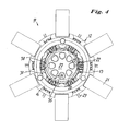
- Figur 4
- einen Schnitt nach der Linie IV-IV in Fig. 3 und die
- Figuren 5 bis 7
- drei verschiedene Ansichten eines Gliedes der Zwischenelemente.
- Die Zeichnungen zeigen eine ausfahrbare Säule 11, die als ein Linearantrieb, eine längenverstellbare Tragsäule oder dgl. verwendbar ist. Sie besitzt einen Sockel 12, der z.B. auf einem Boden- oder Maschinenteil abgestützt sein kann, einen aus dem Sockel ausfahrbaren und damit längenveränderlichen Säulenschaft 13 und einen den Säulenschaft begrenzenden Säulenkopf 14.
- Der Sockel ist in seiner Grundform kreisförmig mit einem Basisabschnitt 15 und einem den unteren Teil des Säulenschaftes 13 umgebenden Kragen 16. In dem Basisabschnitt 15 sind Führungen 17, 18 vorgesehen, die vom Säulenschaft aus kurvig oder schräg nach außen führen. In der Führung 17 ist ein bombiertes Band 20 geführt, das außerhalb des Sockels sich als Rolle 21 selbsttätig aufrollt. Insgesamt sind im dargestellten Beispiel sechs solcher Bänder am Umfang vorhanden.
- Die Bänder bestehen aus einem hochfesten flexiblen Material, beispielsweise Federstahl, das durch eine Bombierung so unter Spannung versetzt wird, dass es in gestrecktem Zustand eine Bombierung oder Wölbung quer zur Längsrichtung des Bandes erhält, die das Band im gestrecktem Zustand versteift und damit die Übertragung recht erheblicher Druckkräfte ohne Ausknicken ermöglicht. Wenn es jedoch, z.B. durch partielles Eindrücken der Bombierung, geknickt wird, rollt es sich automatisch zu der Rolle 21 auf. Solche Bänder sind z.B. von der Firma COBRA Bandstahl GmbH, Wächtersbach, zu beziehen.
- Die insgesamt sechs Bänder sind mit ihren Enden am Kopf 14 befestigt, so dass sie, mit ihrer Bombierung jeweils nach außen weisend, gleichmäßig um den Umfang des Säulenschaftes 13 angeordnet sind und laufen dann vom Säulenschaft in die Führung 17 des Sockels hinein, wo sie innerhalb der Führung eine reversible Knickung erfahren, so dass sie dann aus der Führung 17 am Umfang des Sockels herauslaufen und dort die Rolle oder den Wickel 21 bilden.
- Zwischen den Bändern 20 ist, wie die Fig. 4 zeigt, jeweils eine Lücke vorgesehen, in der Zwischenelemente 22 angeordnet sind. Die Zwischenelemente 22 bestehen aus einem Strang aus einzelnen Gliedern, die in den Figuren 5 und 6 im Detail dargestellt sind. Die aus Metall oder Kunststoff bestehenden Gliedern 23 haben auf beiden Seiten jeweils eine Fläche 24, mit der sie sich aneinander abstützen. Diese Fläche kann leicht gewölbt sein, um ein Abrollen beim Biegen des Stranges zu ermöglichen. An beiden Seiten sind Schlitze oder Nuten 25 mit Einführschrägen vorgesehen, in die die Seitenränder der Bänder 20 eingreifen können (in Fig. 5 strichliert angedeutet). Zur Innenseite des Säulenschaftes 13 weisend, sind Antriebselemente 26 vorgesehen, die nach Art von Zähnen nach innen vorstehen und soviel schmaler sind als die Abmessung des Gliedes in Richtung der Säulenachse 27, dass dazwischen Gewindegänge mit Flanken 35 einer zentralen Schraube oder Schnecke 27, die ein Antriebselement für die Ausfahrbewegung bildet, eingreifen können. Dieser Antriebseingriff geschieht in dem vom Kragen 16 umgebenen Bereich, so dass sich die Zwischenelemente 22 daran abstützen können.
- Die Glieder 23 besitzen ferner im dargestellten Beispiel zwei Öffnungen 28, die eine Aufreihung der Glieder zu einem geschlossenen, das Zwischenelement bildenden Strang 22 mittels im Beispiel zweier verspannter Drahtseilen 29 ermöglicht. Diese sind im Kopf, beispielsweise durch ein verdicktes Ende 30, festgelegt und am anderen Ende des Stranges verspannt. An der nach außen weisenden Seite des Gliedes ist ebenfalls eine Nut 31 vorgesehen, die zur Führung und Andrückung der flexiblen Zwischenelemente durch eine Bügelfeder 32 im Bereich der Führungen 18 dient.
- Die Glieder bilden also einen druck- und zugfest geschlossenen Strang, der jedoch so weit flexibel ist, dass er im Bereich der Führung 18 nach außen abgelenkt und schließlich auch ganz in eine zur Säulenachse 27 radiale Richtung umgelenkt werden kann. Die Führung 18 ist so ausgebildet, dass sie den Strang einerseits in das Gewinde der Schraube 27 einführt, während andererseits die Ränder der Bänder 20 seitlich in die Nuten 25 einlaufen. Dies wird möglich, weil durch die jeweils etwa radiale Zusammenführung der Zwischenelemente-Stränge 22 und der Bänder 20 ein die Einführung ermöglichender Winkel gebildet wird.
- Die das Antriebselement bildende Schraube 27 hat einen Durchmesser, der dem Säulenschaft-Innendurchmesser entspricht. Sie ist in einer zentralen Vertiefung des Sockels um die Säulenachse 27 drehbar gelagert und wird von einem angedeuteten Motor 33 drehbar angetrieben.
- Wenn die Säule eingefahren, d.h. auf geringst mögliche axiale Höhe gefahren ist, liegt der Kopf 14 auf dem Sockel 12 auf. Die Bänder 20 sind weitestmöglich aufgerollt und die Zwischenelemente 22 können gegenüber der in Fig. 3 dargestellten Lage noch weiter in die Horizontale geführt sein. Es ist auch möglich, für sie einen seitlichen, radial vom Sockel hinwegführenden Ausgang zu schaffen, beispielsweise durch einen zusätzlichen Knick oder eine Rundung in der Führung 18.
- Um die Säule auszufahren, wird die Schraube 27 vom Motor 23, ggf. über ein Getriebe, gedreht, so dass die Gewindeflanken 35 mit den Vorsprüngen 26 in Eingriff kommen und den Zwischenelementestrang nach oben verschieben. Dieser kann nicht ausknicken, da seine Nuten 25 mit den Bändern 20 im Eingriff stehen. Die Schraube oder Schnecke 27 arbeitet also mit den insgesamt sechs Zwischenelementen am Umfang wie Schraube und Mutter zusammen. Dieser Antrieb ist normalerweise auch selbsthemmend, so dass für die Tragfunktion der Säule keine Antriebsbremse notwendig ist.
- Bei dem Aufwärtsfahren fädeln sich die durch die Führungen 17 nachgezogenen Bänder 20 in die Nuten 25 der Zwischenelementeglieder 23 ein, so dass sich ein geschlossener zusammenhängender Säulenschaft bildet. Dieser ist im dargestellten Beispiel kreisrund und besteht aus sechs Bändern und sechs Zwischenelementen. Es ist jedoch auch möglich, andere Säulenformen zu erzeugen, wobei zwar die durch die Bombierung der Bänder vorgegebene Krümmung auch als Segment für den Säulenschaftquerschnitt vorteilhaft ist. Es können aber auch davon abweichende Formen, ggf. sogar mit nach innen bombierten Bändern und dementsprechend innen laufenden Rollen erzeugt werden.
- Bei Aufwärtssteigen des Säulenschaftes wird jeweils durch die Führung 17 im Sockel das Band gestreckt und nimmt dadurch seine bombierte Form ein. Nach innen gerichtete gewölbte Vorsprünge 37 in der Ausnehmung 38 des Sockels führen das Band mit einer Linienberührung. Die Spannung des Zwischenelementstranges 22 durch die Zugelemente (jeweils zwei Drahtseile 29 je Strang) schafft einen zugfesten und in Querrichtung relativ knickfesten Strang, jedoch ohne die Flexibilität in der aus den Zeichnungen hervorgehenden Richtung zu behindern.
- Am Kopf 14 ist ein Flansch 36 vorgesehen, über den die mit der Säule bewegten und getragenen Baugruppen angeschlossen werden können.
- Beim Einziehen der Säule wird die Schraube in der entsprechend anderen Richtung gedreht, zieht die Zwischenelementstränge 22 gleichmäßig nach unten, was durch die zugfeste Verbindung nicht präzise möglich ist. Die Bänder rollen sich selbsttätig wieder auf und die Zwischenelementstränge 22 werden seitlich herausgeschoben. Dabei wird das Eindrücken der Bombierung des Bandes 20 zum Aufwickeln von den Vorsprüngen 37 unterstützt.
- Es wird damit eine selbstaufbauende Säule oder Spindel geschaffen, die sich aus einzelnen Strängen und Bändern selbsttätig bei entsprechendem Antrieb zusammensetzt. Bei einer Ausführung ermöglicht ein nur sechs Zentimeter hoher Sockel eine Säulenhöhe von einem Meter.
- Es ist möglich, die Zwischenelementstränge statt aus einzelnen Elementen auch als ein zusammenhängendes Band herzustellen, bei dem z.B. über Filmscharniere die einzelnen Glieder miteinander verbunden sind, was für niedrige Beanspruchung ausreichen kann. Eine Ausführung mit Metallgliedern 23, die sich z.B. über die in den Fig. 5 bis 7 gezeigten Einführschrägen gut in die Bandränder einfügen lassen, hält stärksten Axialkräften Stand, ohne dass Ausknickung zu befürchten ist. Die Bänder bestehen vorzugsweise aus hochfestem Federstahl und sind nur wenige Zehntel Millimeter dick. Sie könnten aber bei bestimmten Anforderungen auch aus anderen Materialien bestehen, die die entsprechende Festigkeit und einen Elastizitätsmodul aufweisen, beispielsweise aus kohlenstofffaserverstärktem Kunststoff.
Claims (12)
- Ausfahrbare Säule (11) mit einem Sockel (12), einem aus dem Sockel ausfahrbaren Säulenschaft (13), einem Kopf (14) und einem Antrieb (27, 33), dadurch gekennzeichnet, dass der Säulenschaft (13) mehrere über den Umfang des Säulenschafts verteilte flexible, im Säulenbereich bombierte Bänder (20) aufweist.
- Säule nach Anspruch 1, dadurch gekennzeichnet, dass die Bänder (20) im Bereich des Sockels (12) aufrollbar, vorzugsweise selbstaufrollend, sind.
- Säule nach Anspruch 1 oder 2, dadurch gekennzeichnet, dass die Bänder (20) durch Führungen (17) den Sockel (12) zwischen einer äußeren aufgerollten Lage und einer im wesentlichen geradlinigen, parallel zur Säulenachse (27) verlaufenden Lage geführt sind, in der sie selbst versteifend bombiert sind.
- Säule nach einem der vorhergehenden Ansprüche, dadurch gekennzeichnet, dass die Bänder bombierte Federstahlbänder sind.
- Säule nach einem der vorhergehenden Ansprüche, dadurch gekennzeichnet, dass im Säulenschaftbereich (13) zwischen die Bänder (20) Zwischenelemente (22) eingefügt sind, die die Bänder (20) in ihren Randbereichen miteinander verbinden.
- Säule nach Anspruch 5, dadurch gekennzeichnet, dass die Zwischenelemente (22) Glieder beinhalten, die einen druck- und vorzugsweise auch zugfesten, jedoch zumindest in einer Richtung flexiblen kettenartigen Strang bilden.
- Säule nach Anspruch 6, dadurch gekennzeichnet, dass die Zwischenelemente (22) Antriebselemente (26), wie zahnartige Vorsprünge, an den Gliedern (23) aufweisen, die von einem Antriebsgetriebe (27), wie einer zur Säule konzentrischen Schraube oder Schnecke, zu einem Längstransport in Richtung der Säulenachse (27) angetrieben werden.
- Säule nach Anspruch 6 oder 7, dadurch gekennzeichnet, dass die Glieder (23) seitliche Aufnahmen (25) für die Außenränder der Bänder (20) haben, in die die Bänder (20) im Bereich des Sockels (10) eingreifen.
- Säule nach einem der Ansprüche 5 bis 8, dadurch gekennzeichnet, dass die flexiblen Zwischenelemente (22) in einer Führung (18) des Sockels (12) nach außen umlenkbar sind.
- Säule nach einem der Ansprüche 6 bis 9, dadurch gekennzeichnet, dass die Zwischenelemente (22) durch Zugelemente (29), wie flexible Drahtseile, die durch Öffnungen (28) in den Gliedern (28) gespannt sind, zugfest verbunden sind.
- Säule nach einem der Ansprüche 5 bis 10, dadurch gekennzeichnet, dass im Bereich der Führungen (18) für die Zwischenelemente (22) Andruckelemente (32) die Zwischenelemente (22) nach innen andrücken.
- Säule nach einem der Ansprüche 5 bis 11, dadurch gekennzeichnet, dass der Sockel (12) abwechselnd Führungen (17) für die Bänder (20) und Führungen (18) für die Zwischenelemente (22) aufweist, die in eine Mittelöffnung des Sockels (12) liegen, die von einem Führungskragen (16) des Sockels umgeben ist und in der ggf. eine Antriebsschraube (27) um die Säulenachse (17) drehbar angetrieben gelagert ist.
Applications Claiming Priority (1)
| Application Number | Priority Date | Filing Date | Title |
|---|---|---|---|
| DE102006018965A DE102006018965A1 (de) | 2006-04-19 | 2006-04-19 | Ausfahrbare Säule |
Publications (3)
| Publication Number | Publication Date |
|---|---|
| EP1847729A2 true EP1847729A2 (de) | 2007-10-24 |
| EP1847729A3 EP1847729A3 (de) | 2008-05-28 |
| EP1847729B1 EP1847729B1 (de) | 2010-06-16 |
Family
ID=38325548
Family Applications (1)
| Application Number | Title | Priority Date | Filing Date |
|---|---|---|---|
| EP07007486A Not-in-force EP1847729B1 (de) | 2006-04-19 | 2007-04-12 | Ausfahrbare Säule |
Country Status (4)
| Country | Link |
|---|---|
| EP (1) | EP1847729B1 (de) |
| AT (1) | ATE471470T1 (de) |
| DE (2) | DE102006018965A1 (de) |
| DK (1) | DK1847729T3 (de) |
Cited By (1)
| Publication number | Priority date | Publication date | Assignee | Title |
|---|---|---|---|---|
| EP2520827A3 (de) * | 2011-05-02 | 2013-09-04 | Waagner-Biro Austria Stage Systems AG | Hebevorrichtung zum vertikalen Anheben von Lasten |
Citations (2)
| Publication number | Priority date | Publication date | Assignee | Title |
|---|---|---|---|---|
| DE3838724A1 (de) | 1987-12-07 | 1989-06-22 | Schmid Hans Armin | Vorrichtung zum fuehren eines bombierten bandes |
| EP0363939A1 (de) | 1988-10-14 | 1990-04-18 | Hans Armin Dr. Schmid | Getriebe zum Umsetzen einer translatorischen Bewegung in eine Drehbewegung und umgekehrt |
Family Cites Families (6)
| Publication number | Priority date | Publication date | Assignee | Title |
|---|---|---|---|---|
| DE862321C (de) * | 1942-09-05 | 1953-01-08 | Telefunken Gmbh | Antennenmasten und Galgenarme fuer Mikrofongalgen |
| US4225871A (en) * | 1977-06-28 | 1980-09-30 | Luigi Ramari | Collapsible, flattenable and drum wrappable type of radio antenna, particularly for motor-vehicles and moving equipments |
| DE3328889A1 (de) * | 1983-08-10 | 1985-02-28 | Hörmann KG Antriebs- und Steuerungstechnik, 4834 Harsewinkel | Geraet zur ueberfuehrung einer rotatorischen in eine translatorische bewegung |
| DE3419477C1 (de) * | 1984-05-24 | 1985-11-28 | Hörmann KG Antriebs- und Steuerungstechnik, 4834 Harsewinkel | Getriebe zur UEberfuehrung einer rotatorischen in eine translatorische Bewegung |
| GB8710332D0 (en) * | 1987-04-30 | 1987-06-03 | Daton Lovett A J | Extensible elements |
| DE10103490A1 (de) * | 2001-01-26 | 2002-08-14 | Walter Gobbers | Zahnstange |
-
2006
- 2006-04-19 DE DE102006018965A patent/DE102006018965A1/de not_active Withdrawn
-
2007
- 2007-04-12 DK DK07007486.9T patent/DK1847729T3/da active
- 2007-04-12 DE DE502007004110T patent/DE502007004110D1/de active Active
- 2007-04-12 EP EP07007486A patent/EP1847729B1/de not_active Not-in-force
- 2007-04-12 AT AT07007486T patent/ATE471470T1/de active
Patent Citations (2)
| Publication number | Priority date | Publication date | Assignee | Title |
|---|---|---|---|---|
| DE3838724A1 (de) | 1987-12-07 | 1989-06-22 | Schmid Hans Armin | Vorrichtung zum fuehren eines bombierten bandes |
| EP0363939A1 (de) | 1988-10-14 | 1990-04-18 | Hans Armin Dr. Schmid | Getriebe zum Umsetzen einer translatorischen Bewegung in eine Drehbewegung und umgekehrt |
Cited By (1)
| Publication number | Priority date | Publication date | Assignee | Title |
|---|---|---|---|---|
| EP2520827A3 (de) * | 2011-05-02 | 2013-09-04 | Waagner-Biro Austria Stage Systems AG | Hebevorrichtung zum vertikalen Anheben von Lasten |
Also Published As
| Publication number | Publication date |
|---|---|
| EP1847729A3 (de) | 2008-05-28 |
| DK1847729T3 (da) | 2010-10-11 |
| DE502007004110D1 (de) | 2010-07-29 |
| EP1847729B1 (de) | 2010-06-16 |
| ATE471470T1 (de) | 2010-07-15 |
| DE102006018965A1 (de) | 2007-10-25 |
Similar Documents
| Publication | Publication Date | Title |
|---|---|---|
| EP1905625B1 (de) | Rollo mit hinterschneidungsfreier Führungsschiene | |
| EP2913577B1 (de) | Abdeckvorrichtung für Öffnungen, insbesondere für Maschinenöffnungen | |
| EP1970235B1 (de) | Seitenfensterrollo mit Seilantrieb | |
| EP2813134B1 (de) | Stabband für Stabbandförderer landwirtschaftlicher Maschinen | |
| DE19843259C1 (de) | Verstellbarer Bettlattenrost | |
| EP3620425A1 (de) | Verfahrbarer personenlift | |
| DE102006046069A1 (de) | Fensterrollo mit reibungsmindertem Antrieb | |
| WO2008071617A2 (de) | Linearführungsmodul umfassend einen führungswagen | |
| DE102013210406B4 (de) | Wandelbares Dachelement, wandelbare Dachkonstruktion und Verfahren zum Betrieb des Dachelements | |
| DE3047800C2 (de) | Antriebsmechanismus | |
| DE69900555T2 (de) | Verfahren und vorrichtung zur übertragung von druck und/oder zugkraft | |
| DE60222689T2 (de) | Vorrichtung zur erleichterung der handhabung von spulen oder haspeln durch rollen und schwenken auf dem boden | |
| DE202013102410U1 (de) | Wandelbares Dachelement, wandelbare Dachkonstruktion | |
| EP1847729B1 (de) | Ausfahrbare Säule | |
| EP1886599B1 (de) | Vorrichtung zum bewegen eines ersten möbelteils relativ zu einem zweiten möbelteil und möbel | |
| DE9403006U1 (de) | Sonnenschutzvorrichtung | |
| CH711696B1 (de) | Spinn- oder Zwirnmaschine mit hubbewegbarer Spindelbank. | |
| EP4033047B1 (de) | Sonnenschutzanlage mit einem zugsystem | |
| DE1605975C3 (de) | Fensterheber fur in den Fensterschacht eines Kraftfahrzeuges versenkbare Schiebefenster | |
| DE29512889U1 (de) | Sonnenschutz, insbesondere für Kfz-Dachfenster | |
| AT521969B1 (de) | Vorrichtung zum Bewegen eines Spreizbands | |
| DE102006046064A1 (de) | Manuell betätigtes Fensterrollo | |
| DE3222302C2 (de) | ||
| DE10024075A1 (de) | Scherenhubvorrichtung | |
| DE102013106274A1 (de) | Bandhaspelanordnung zum Auf- und/oder Abwickeln eines Metallbandes |
Legal Events
| Date | Code | Title | Description |
|---|---|---|---|
| PUAI | Public reference made under article 153(3) epc to a published international application that has entered the european phase |
Free format text: ORIGINAL CODE: 0009012 |
|
| AK | Designated contracting states |
Kind code of ref document: A2 Designated state(s): AT BE BG CH CY CZ DE DK EE ES FI FR GB GR HU IE IS IT LI LT LU LV MC MT NL PL PT RO SE SI SK TR |
|
| AX | Request for extension of the european patent |
Extension state: AL BA HR MK YU |
|
| PUAL | Search report despatched |
Free format text: ORIGINAL CODE: 0009013 |
|
| AK | Designated contracting states |
Kind code of ref document: A3 Designated state(s): AT BE BG CH CY CZ DE DK EE ES FI FR GB GR HU IE IS IT LI LT LU LV MC MT NL PL PT RO SE SI SK TR |
|
| AX | Request for extension of the european patent |
Extension state: AL BA HR MK RS |
|
| 17P | Request for examination filed |
Effective date: 20081128 |
|
| 17Q | First examination report despatched |
Effective date: 20090108 |
|
| AKX | Designation fees paid |
Designated state(s): AT BE BG CH CY CZ DE DK EE ES FI FR GB GR HU IE IS IT LI LT LU LV MC MT NL PL PT RO SE SI SK TR |
|
| GRAP | Despatch of communication of intention to grant a patent |
Free format text: ORIGINAL CODE: EPIDOSNIGR1 |
|
| GRAS | Grant fee paid |
Free format text: ORIGINAL CODE: EPIDOSNIGR3 |
|
| GRAA | (expected) grant |
Free format text: ORIGINAL CODE: 0009210 |
|
| AK | Designated contracting states |
Kind code of ref document: B1 Designated state(s): AT BE BG CH CY CZ DE DK EE ES FI FR GB GR HU IE IS IT LI LT LU LV MC MT NL PL PT RO SE SI SK TR |
|
| REG | Reference to a national code |
Ref country code: CH Ref legal event code: EP |
|
| REG | Reference to a national code |
Ref country code: IE Ref legal event code: FG4D Free format text: LANGUAGE OF EP DOCUMENT: GERMAN |
|
| REF | Corresponds to: |
Ref document number: 502007004110 Country of ref document: DE Date of ref document: 20100729 Kind code of ref document: P |
|
| REG | Reference to a national code |
Ref country code: DK Ref legal event code: T3 |
|
| REG | Reference to a national code |
Ref country code: NL Ref legal event code: VDEP Effective date: 20100616 |
|
| PG25 | Lapsed in a contracting state [announced via postgrant information from national office to epo] |
Ref country code: LT Free format text: LAPSE BECAUSE OF FAILURE TO SUBMIT A TRANSLATION OF THE DESCRIPTION OR TO PAY THE FEE WITHIN THE PRESCRIBED TIME-LIMIT Effective date: 20100616 Ref country code: SE Free format text: LAPSE BECAUSE OF FAILURE TO SUBMIT A TRANSLATION OF THE DESCRIPTION OR TO PAY THE FEE WITHIN THE PRESCRIBED TIME-LIMIT Effective date: 20100616 |
|
| LTIE | Lt: invalidation of european patent or patent extension |
Effective date: 20100616 |
|
| PG25 | Lapsed in a contracting state [announced via postgrant information from national office to epo] |
Ref country code: LV Free format text: LAPSE BECAUSE OF FAILURE TO SUBMIT A TRANSLATION OF THE DESCRIPTION OR TO PAY THE FEE WITHIN THE PRESCRIBED TIME-LIMIT Effective date: 20100616 Ref country code: SI Free format text: LAPSE BECAUSE OF FAILURE TO SUBMIT A TRANSLATION OF THE DESCRIPTION OR TO PAY THE FEE WITHIN THE PRESCRIBED TIME-LIMIT Effective date: 20100616 Ref country code: FI Free format text: LAPSE BECAUSE OF FAILURE TO SUBMIT A TRANSLATION OF THE DESCRIPTION OR TO PAY THE FEE WITHIN THE PRESCRIBED TIME-LIMIT Effective date: 20100616 |
|
| PG25 | Lapsed in a contracting state [announced via postgrant information from national office to epo] |
Ref country code: CY Free format text: LAPSE BECAUSE OF FAILURE TO SUBMIT A TRANSLATION OF THE DESCRIPTION OR TO PAY THE FEE WITHIN THE PRESCRIBED TIME-LIMIT Effective date: 20100616 Ref country code: PL Free format text: LAPSE BECAUSE OF FAILURE TO SUBMIT A TRANSLATION OF THE DESCRIPTION OR TO PAY THE FEE WITHIN THE PRESCRIBED TIME-LIMIT Effective date: 20100616 |
|
| REG | Reference to a national code |
Ref country code: IE Ref legal event code: FD4D |
|
| PG25 | Lapsed in a contracting state [announced via postgrant information from national office to epo] |
Ref country code: EE Free format text: LAPSE BECAUSE OF FAILURE TO SUBMIT A TRANSLATION OF THE DESCRIPTION OR TO PAY THE FEE WITHIN THE PRESCRIBED TIME-LIMIT Effective date: 20100616 Ref country code: GR Free format text: LAPSE BECAUSE OF FAILURE TO SUBMIT A TRANSLATION OF THE DESCRIPTION OR TO PAY THE FEE WITHIN THE PRESCRIBED TIME-LIMIT Effective date: 20100917 Ref country code: IE Free format text: LAPSE BECAUSE OF FAILURE TO SUBMIT A TRANSLATION OF THE DESCRIPTION OR TO PAY THE FEE WITHIN THE PRESCRIBED TIME-LIMIT Effective date: 20100616 Ref country code: NL Free format text: LAPSE BECAUSE OF FAILURE TO SUBMIT A TRANSLATION OF THE DESCRIPTION OR TO PAY THE FEE WITHIN THE PRESCRIBED TIME-LIMIT Effective date: 20100616 |
|
| PG25 | Lapsed in a contracting state [announced via postgrant information from national office to epo] |
Ref country code: IS Free format text: LAPSE BECAUSE OF FAILURE TO SUBMIT A TRANSLATION OF THE DESCRIPTION OR TO PAY THE FEE WITHIN THE PRESCRIBED TIME-LIMIT Effective date: 20101016 Ref country code: SK Free format text: LAPSE BECAUSE OF FAILURE TO SUBMIT A TRANSLATION OF THE DESCRIPTION OR TO PAY THE FEE WITHIN THE PRESCRIBED TIME-LIMIT Effective date: 20100616 Ref country code: CZ Free format text: LAPSE BECAUSE OF FAILURE TO SUBMIT A TRANSLATION OF THE DESCRIPTION OR TO PAY THE FEE WITHIN THE PRESCRIBED TIME-LIMIT Effective date: 20100616 Ref country code: PT Free format text: LAPSE BECAUSE OF FAILURE TO SUBMIT A TRANSLATION OF THE DESCRIPTION OR TO PAY THE FEE WITHIN THE PRESCRIBED TIME-LIMIT Effective date: 20101018 Ref country code: RO Free format text: LAPSE BECAUSE OF FAILURE TO SUBMIT A TRANSLATION OF THE DESCRIPTION OR TO PAY THE FEE WITHIN THE PRESCRIBED TIME-LIMIT Effective date: 20100616 |
|
| PG25 | Lapsed in a contracting state [announced via postgrant information from national office to epo] |
Ref country code: IT Free format text: LAPSE BECAUSE OF FAILURE TO SUBMIT A TRANSLATION OF THE DESCRIPTION OR TO PAY THE FEE WITHIN THE PRESCRIBED TIME-LIMIT Effective date: 20100616 |
|
| PLBE | No opposition filed within time limit |
Free format text: ORIGINAL CODE: 0009261 |
|
| STAA | Information on the status of an ep patent application or granted ep patent |
Free format text: STATUS: NO OPPOSITION FILED WITHIN TIME LIMIT |
|
| 26N | No opposition filed |
Effective date: 20110317 |
|
| REG | Reference to a national code |
Ref country code: DE Ref legal event code: R097 Ref document number: 502007004110 Country of ref document: DE Effective date: 20110316 |
|
| PG25 | Lapsed in a contracting state [announced via postgrant information from national office to epo] |
Ref country code: MC Free format text: LAPSE BECAUSE OF NON-PAYMENT OF DUE FEES Effective date: 20110430 |
|
| REG | Reference to a national code |
Ref country code: CH Ref legal event code: PL |
|
| GBPC | Gb: european patent ceased through non-payment of renewal fee |
Effective date: 20110412 |
|
| PG25 | Lapsed in a contracting state [announced via postgrant information from national office to epo] |
Ref country code: MT Free format text: LAPSE BECAUSE OF FAILURE TO SUBMIT A TRANSLATION OF THE DESCRIPTION OR TO PAY THE FEE WITHIN THE PRESCRIBED TIME-LIMIT Effective date: 20100616 |
|
| PG25 | Lapsed in a contracting state [announced via postgrant information from national office to epo] |
Ref country code: LI Free format text: LAPSE BECAUSE OF NON-PAYMENT OF DUE FEES Effective date: 20110430 Ref country code: CH Free format text: LAPSE BECAUSE OF NON-PAYMENT OF DUE FEES Effective date: 20110430 |
|
| PG25 | Lapsed in a contracting state [announced via postgrant information from national office to epo] |
Ref country code: GB Free format text: LAPSE BECAUSE OF NON-PAYMENT OF DUE FEES Effective date: 20110412 |
|
| PGFP | Annual fee paid to national office [announced via postgrant information from national office to epo] |
Ref country code: BE Payment date: 20120424 Year of fee payment: 6 Ref country code: DK Payment date: 20120424 Year of fee payment: 6 Ref country code: DE Payment date: 20120502 Year of fee payment: 6 |
|
| PGFP | Annual fee paid to national office [announced via postgrant information from national office to epo] |
Ref country code: FR Payment date: 20120511 Year of fee payment: 6 |
|
| PGFP | Annual fee paid to national office [announced via postgrant information from national office to epo] |
Ref country code: AT Payment date: 20120420 Year of fee payment: 6 |
|
| PG25 | Lapsed in a contracting state [announced via postgrant information from national office to epo] |
Ref country code: LU Free format text: LAPSE BECAUSE OF NON-PAYMENT OF DUE FEES Effective date: 20110412 |
|
| PG25 | Lapsed in a contracting state [announced via postgrant information from national office to epo] |
Ref country code: BG Free format text: LAPSE BECAUSE OF FAILURE TO SUBMIT A TRANSLATION OF THE DESCRIPTION OR TO PAY THE FEE WITHIN THE PRESCRIBED TIME-LIMIT Effective date: 20100916 Ref country code: TR Free format text: LAPSE BECAUSE OF FAILURE TO SUBMIT A TRANSLATION OF THE DESCRIPTION OR TO PAY THE FEE WITHIN THE PRESCRIBED TIME-LIMIT Effective date: 20100616 |
|
| BERE | Be: lapsed |
Owner name: NEFF, KARL Effective date: 20130430 |
|
| PG25 | Lapsed in a contracting state [announced via postgrant information from national office to epo] |
Ref country code: ES Free format text: LAPSE BECAUSE OF FAILURE TO SUBMIT A TRANSLATION OF THE DESCRIPTION OR TO PAY THE FEE WITHIN THE PRESCRIBED TIME-LIMIT Effective date: 20100927 Ref country code: HU Free format text: LAPSE BECAUSE OF FAILURE TO SUBMIT A TRANSLATION OF THE DESCRIPTION OR TO PAY THE FEE WITHIN THE PRESCRIBED TIME-LIMIT Effective date: 20100616 |
|
| REG | Reference to a national code |
Ref country code: DK Ref legal event code: EBP Effective date: 20130430 |
|
| REG | Reference to a national code |
Ref country code: AT Ref legal event code: MM01 Ref document number: 471470 Country of ref document: AT Kind code of ref document: T Effective date: 20130430 |
|
| PG25 | Lapsed in a contracting state [announced via postgrant information from national office to epo] |
Ref country code: AT Free format text: LAPSE BECAUSE OF NON-PAYMENT OF DUE FEES Effective date: 20130430 Ref country code: BE Free format text: LAPSE BECAUSE OF NON-PAYMENT OF DUE FEES Effective date: 20130430 Ref country code: DE Free format text: LAPSE BECAUSE OF NON-PAYMENT OF DUE FEES Effective date: 20131101 |
|
| REG | Reference to a national code |
Ref country code: FR Ref legal event code: ST Effective date: 20131231 |
|
| REG | Reference to a national code |
Ref country code: DE Ref legal event code: R119 Ref document number: 502007004110 Country of ref document: DE Effective date: 20131101 |
|
| PG25 | Lapsed in a contracting state [announced via postgrant information from national office to epo] |
Ref country code: FR Free format text: LAPSE BECAUSE OF NON-PAYMENT OF DUE FEES Effective date: 20130430 |
|
| PG25 | Lapsed in a contracting state [announced via postgrant information from national office to epo] |
Ref country code: DK Free format text: LAPSE BECAUSE OF NON-PAYMENT OF DUE FEES Effective date: 20130430 |