EP1847170B1 - Rotorumkehrmechanismus - Google Patents
Rotorumkehrmechanismus Download PDFInfo
- Publication number
- EP1847170B1 EP1847170B1 EP07106331A EP07106331A EP1847170B1 EP 1847170 B1 EP1847170 B1 EP 1847170B1 EP 07106331 A EP07106331 A EP 07106331A EP 07106331 A EP07106331 A EP 07106331A EP 1847170 B1 EP1847170 B1 EP 1847170B1
- Authority
- EP
- European Patent Office
- Prior art keywords
- reversing
- rotor
- reversing arm
- arm
- spring
- Prior art date
- Legal status (The legal status is an assumption and is not a legal conclusion. Google has not performed a legal analysis and makes no representation as to the accuracy of the status listed.)
- Active
Links
- 238000003306 harvesting Methods 0.000 claims description 4
- 238000004873 anchoring Methods 0.000 claims description 2
- 238000013459 approach Methods 0.000 claims description 2
- 239000012530 fluid Substances 0.000 description 6
- 230000007935 neutral effect Effects 0.000 description 5
- 239000011800 void material Substances 0.000 description 2
- 230000004913 activation Effects 0.000 description 1
- 238000010276 construction Methods 0.000 description 1
- 239000004459 forage Substances 0.000 description 1
- 239000000463 material Substances 0.000 description 1
- 238000000034 method Methods 0.000 description 1
- 230000000116 mitigating effect Effects 0.000 description 1
- 230000002028 premature Effects 0.000 description 1
- 239000010902 straw Substances 0.000 description 1
Images

Classifications
-
- A—HUMAN NECESSITIES
- A01—AGRICULTURE; FORESTRY; ANIMAL HUSBANDRY; HUNTING; TRAPPING; FISHING
- A01D—HARVESTING; MOWING
- A01D69/00—Driving mechanisms or parts thereof for harvesters or mowers
-
- A—HUMAN NECESSITIES
- A01—AGRICULTURE; FORESTRY; ANIMAL HUSBANDRY; HUNTING; TRAPPING; FISHING
- A01F—PROCESSING OF HARVESTED PRODUCE; HAY OR STRAW PRESSES; DEVICES FOR STORING AGRICULTURAL OR HORTICULTURAL PRODUCE
- A01F15/00—Baling presses for straw, hay or the like
- A01F15/08—Details
- A01F15/0841—Drives for balers
-
- A—HUMAN NECESSITIES
- A01—AGRICULTURE; FORESTRY; ANIMAL HUSBANDRY; HUNTING; TRAPPING; FISHING
- A01D—HARVESTING; MOWING
- A01D90/00—Vehicles for carrying harvested crops with means for selfloading or unloading
- A01D90/14—Adaptations of gearing for driving, loading or unloading means
-
- A—HUMAN NECESSITIES
- A01—AGRICULTURE; FORESTRY; ANIMAL HUSBANDRY; HUNTING; TRAPPING; FISHING
- A01F—PROCESSING OF HARVESTED PRODUCE; HAY OR STRAW PRESSES; DEVICES FOR STORING AGRICULTURAL OR HORTICULTURAL PRODUCE
- A01F15/00—Baling presses for straw, hay or the like
- A01F15/08—Details
- A01F15/10—Feeding devices for the crop material e.g. precompression devices
Definitions
- the present invention relates to a rotor reversing mechanism for a feeder in an agricultural harvesting machine and can be used with both round and square balers or any other rotor type in-feed system (see e.g. DE 195 34 138 C1 ).
- the rotor of a baler is the part used to propel the straw picked up from the ground into the baling chamber of a baler where it is compacted and formed into bales.
- the rotor can also be part of an in-feed or transport element for other processing means.
- a blockage of the rotor may occur from time to time resulting in activation of the overload safety device in the drive line.
- the drive is interrupted and, in such an event, the operator has to switch off the drive to the baler and rotate the rotor in the reverse sense to release the blockage.
- a baler rotor with a reversing mechanism which comprises a ratchet mounted on the rotor and a pawl carried on a reversing arm that is reciprocated by means of a double acting hydraulic cylinder.
- a double acting hydraulic cylinder When the reversing arm is extended fully into a park position, the pawl is disengaged from the ratchet to allow the drive to rotate the rotor in its normal forward direction.
- a problem that arises when using such a reversing mechanism is that the operator can accidentally re-engage the drive to the baler before the reversing arm has reached its park position, that is to say while forward rotation of the rotor is being opposed by engagement between the pawl and the ratchet. Such premature re-engagement of the drive to the baler can result in serious and possibly irreparable damage to the reversing mechanism.
- the present invention provides a reversing mechanism for a rotor of an in-feed system of an agricultural harvesting machine, comprising a ratchet mounted for rotation with the rotor, a pawl carried by a reversing arm for engaging the ratchet, a double acting hydraulic cylinder for reciprocating the reversing arm to cause the rotor to rotate in a reverse direction, means for disengaging the pawl from the ratchet when the reversing arm is in a park position, and a spring for urging the reversing arm towards the park position and a spring for urging the reversing arm towards the park position characterised in that the working chambers of the double acting hydraulic cylinder are permanently connected to one another by way of a throttled passage.
- the agricultural harvesting machine may be a baler, such as a round or a rectangular baler, a loading wagon, a forage harvester, or some other type of machinery collecting crop material from a field.
- a baler such as a round or a rectangular baler, a loading wagon, a forage harvester, or some other type of machinery collecting crop material from a field.
- the hydraulic supply to the double acting hydraulic cylinder is normally derived from a four port three position valve on the tractor.
- the ports include two input ports and two output ports.
- the input ports are connected to a high pressure and a drain, respectively, while the two output ports lead to the working chambers on the opposite sides of the piston of the hydraulic cylinder.
- In a neutral central position of the valve all the ports are isolated.
- the high pressure input port is connected to a first of the working chambers and the drain is connected to the second.
- the connections to the working chambers are reversed, that is to say the first working chamber is connected to drain while the second is connected to the high pressure input port.
- the passage connecting the two working chambers creates a short circuit in parallel with the hydraulic cylinder.
- the degree of throttling provided in the passage is necessarily a compromise in that the greater the throttling the higher the pressure developed across the passage to operate the hydraulic cylinder.
- the throttling also acts to damp the movement of the reversing arm towards the park position, reducing the degree of throttling enables the reversing arm to return to the park position more quickly.
- the faces of the piston of the double acting cylinder may have an equal surface area but this makes for a more expensive construction of the cylinder. More usually, because the piston rod projects from only one end of the cylinder, the piston faces are of unequal area and the piston acts as a differential piston.
- the piston is a differential piston and the pressure acting on the larger face of the piston acts to move the reversing arm towards the park position.
- the volume of fluid discharged from the working chamber with the smaller cross sectional area is always less than the volume available in the chamber on the opposite side of the piston to accommodate the discharge fluid. Consequently, the risk of hydraulic lock does not arise, though a void (filled with a Torricellian vacuum) will be developed in the working chamber with the larger cross sectional area.
- a differential piston also affects the speed of movement of the reversing arm, causing it to move more rapidly towards the park position than away from the park position. This is advantageous in that it reduces the risk of the drive to the rotor being re-engaged before the pawl has been disengaged from the ratchet.
- the reversing arm is preferably mounted for rotation about the axis of the rotor and the pawl is pivotably mounted on the reversing arm in such a manner as to engage with the ratchet teeth under the action of a spring, the pawl being pivoted against the action of the spring when it comes into a contact with a stationary abutment in the park position of the reversing arm.
- the spring may act directly on the reversing arm, it is preferred for the spring to act on the reversing arm by way of a lever system designed to increase the spring force acting on the reversing arm as it approaches the park position.
- the spring lever system may conveniently comprise a first lever rotatable at one end about an axis that is fixed in relation to the rotor axis and carrying at its opposite end a two-armed lever, one arm of the two-armed lever being connected to the reversing arm and the other to a spring of which the opposite end is anchored to a point that is fixed relative to the axis of the rotor.
- the two-armed lever is a bell crank lever and the anchoring point of the spring coincides with the pivot axis of the first lever.
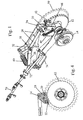
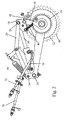
- the sprocket 10 is used to drive the rotor of a baler, the rotor not being shown in the drawings.
- a ratchet 12 is mounted on the same axis for rotation with the rotor as is a second sprocket 14 which is used to transmit drive to a pickup.
- blockages develop from time to time within the baler and these are freed by rotating the rotor in the reverse direction.
- the present invention is concerned only with the reversing mechanism and only the parts concerned with driving the rotor in the reverse direction will now be described in detail.
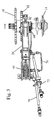
- the reversing mechanism comprises a reversing arm 16 rotatable about the axis of the rotor and carrying a head 18 which is shown in section in Fig. 4 .
- the head 18 can pivot relative to the reversing arm 16 about a pivot bolt 20 and it carries a pawl 22 which engages the teeth of the ratchet 12.
- the head 18 is pivotably connected to the end of the rod 30 of a double acting hydraulic jack 32 of which the cylinder is pivotably mounted about a fixed pivot bolt 34.
- the rod 30 of the hydraulic jack 32 is retracted from the park position shown in Fig. 2 .
- Pulling on the pivot point 24 causes of the head 18 to pivot about the bolt 20 so that the pawl 22 engages in the teeth of the ratchet 12.
- the rod 30 is first extended towards the illustrated position in Fig. 2 .
- the head 18 of the reversing arm is additionally pivotably connected at the point 24 to a spring biased lever system that urges the reversing arm 16 towards the park position.
- the lever system comprises a bell crank lever 26 which is itself pivoted at a central fulcrum 38 about the free end of a lever 28.
- the lever 28 is pivoted about a fixed axis 36 located near the pivot bolt 34.
- the end of one arm of the bell crank lever 26 is pivotably connected to the point 24 on the head 18 of the reversing arm 16 while the free end of the other arm of the bell crank lever 28 is connected by way of a coil spring 40 to the pivot 36 of the lever 28.
- the circuit of the hydraulic jack is modified in the manner illustrated in Fig. 5 .
- Fig. 5 the parts of the hydraulic circuit shown to the left of the dotted line 50 form part of the tractor towing the baler.
- Two connectors 52 and 54 lead to a manually controlled three position valve 56.
- Two ports on the input side of the valve 56 are connected to a hydraulic pump 58 and a reservoir 60, respectively.
- the pump 58 In the central position of the valve, as illustrated in Fig, 5 , the pump 58 is connected to the reservoir 60 while both the output ports are blocked off.
- the valve connects one of the output ports to the pump 58 and the other output port to the reservoir 60 while in the opposite end position these connections are reversed.
- the hydraulic jack 32 has two working chambers 62 and 64. Because of the cross-sectional area of the rod 30, the piston 66 acts as a differential piston and the cross sectional areas of the two working chambers 62 and 64 are unequal.
- the working chamber 62 is connected by a pipe 70 to the connector 52 while the working chamber 64 is connected by a pipe 72 to the connector 54.
- the hydraulic circuit is conventional.
- the rod 30 is retracted by moving the valve 56 to the first end position in which the working chamber 64 is connected to the pump 58 and the larger working chamber is connected to the reservoir 60.
- fluid will also flow from the pump 58 to the reservoir 60 through the throttled passage 74 but the size of the throttle ensures that sufficient pressure difference exists between the two working chambers to retract the rod 30 and rotate the rotor in the reverse direction.
- valve 56 is moved to the other end position to connect the pump 58 to the larger working chamber 62 and the smaller working chamber 62 to the reservoir.
Landscapes
- Life Sciences & Earth Sciences (AREA)
- Environmental Sciences (AREA)
- Soil Working Implements (AREA)
- Medicines Containing Plant Substances (AREA)
- Centrifugal Separators (AREA)
- Hydraulic Motors (AREA)
- Transmission Devices (AREA)
- Actuator (AREA)
Claims (6)
- Umkehr-Mechanismus für einen Rotor eines Zuführungssystems einer landwirtschaftlichen Erntemaschine, mit einem Klinkenrad (12), dass für eine Drehung mit dem Rotor befestigt ist, einer Sperrklinke (22), die von einem Umkehr-Arm (16) für einen Eingriff mit dem Klinkenrad getragen wird, einem doppelwirkenden Hydraulikzylinder (32) zum Hin und Herbewegen des Umkehr-Arms zum Hervorrufen einer Drehung des Rotors in einer umgekehrten Richtung, Einrichtungen (42) zum Ausrücken der Sperrklinke aus dem Klinkenrad, wenn sich der Umkehr-Arm in einer Parkstellung befindet, und einer Feder zum Drücken des Umkehr-Arms in Richtung auf die Parkstellung;
dadurch gekennzeichnet, dass die Arbeitskammern (62, 64) des doppelwirkenden Hydraulikzylinders (32) dauernd miteinander über einen gedrosseltem Kanal (74) verbunden sind. - Umkehr-Mechanismus nach Anspruch 1, dadurch gekennzeichnet, dass der Hydraulikzylinder (32) einen Differenzial-Kolben (66) aufweist, wobei der auf die größere Fläche des Kolbens wirkende Druck betreibbar ist, um den Umkehr-Arm (16) in Richtung auf die Parkstellung zu bewegen.
- Umkehr-Mechanismus nach Anspruch 1 oder 2, dadurch gekennzeichnet, dass der Umkehr-Arm (16) für eine Drehung um die Achse des Rotors befestigt ist und die Sperrklinke (22) schwenkbar auf dem Umkehr-Arm (16) derart befestigt ist, dass sie mit den Zähnen des Klinkenrades (12) unter der Wirkung einer weiteren Feder (44) in Eingriff kommt, wobei die Sperrklinke gegen die Wirkung der weiteren Feder verschwenkt wird, wenn sie in Kontakt mit einem stationären Anschlag (42) in der Parkstellung des Umkehr-Arms (16) kommt.
- Umkehr-Mechanismus nach einem der vorhergehenden Ansprüche, dadurch gekennzeichnet, dass die Feder (40), die den Umkehr-Arm (16) in Richtung auf die Parkstellung drückt, auf den Umkehr-Arm über ein Hebelsystem (26, 28) wirkt, das zur Vergrößerung der Federkraft ausgebildet ist, die auf den Umkehr-Arm wirkt, wenn sich dieser der Parkstellung nähert.
- Umkehr-Mechanismus nach Anspruch 4, dadurch gekennzeichnet, dass das Hebelsystem einen ersten Hebel (28) umfasst, der an einem Ende um eine Achse (36) drehbar ist, die bezüglich der Rotorachse festgelegt ist, und der an seinem entgegengesetzten Ende einen zweiarmigen Hebel (26) trägt, wobei ein Arm des zweiarmigen Hebels mit dem Umkehr-Arm (16) und der andere mit der Feder (40) verbunden ist, die den Umkehr-Arm in Richtung auf die Parkstellung drückt, wobei das entgegengesetzte Ende der letztgenannten Feder an einem Punkt (36) verankert ist, der gegenüber der Achse des Rotors festgelegt ist.
- Umkehr-Mechanismus nach Anspruch 5, dadurch gekennzeichnet, dass der zweiarmige Hebel ein Winkelhebel (26) ist, und dass der Verankerungspunkt (36) der Feder (40) mit der Schwenkachse des ersten Hebels (28) zusammenfällt.
Applications Claiming Priority (1)
| Application Number | Priority Date | Filing Date | Title |
|---|---|---|---|
| GB0607557A GB2437271A (en) | 2006-04-18 | 2006-04-18 | Rotor reversing mechanism |
Publications (2)
| Publication Number | Publication Date |
|---|---|
| EP1847170A1 EP1847170A1 (de) | 2007-10-24 |
| EP1847170B1 true EP1847170B1 (de) | 2008-12-31 |
Family
ID=36571869
Family Applications (1)
| Application Number | Title | Priority Date | Filing Date |
|---|---|---|---|
| EP07106331A Active EP1847170B1 (de) | 2006-04-18 | 2007-04-17 | Rotorumkehrmechanismus |
Country Status (5)
| Country | Link |
|---|---|
| US (1) | US7669400B2 (de) |
| EP (1) | EP1847170B1 (de) |
| AT (1) | ATE418855T1 (de) |
| DE (1) | DE602007000420D1 (de) |
| GB (1) | GB2437271A (de) |
Families Citing this family (5)
| Publication number | Priority date | Publication date | Assignee | Title |
|---|---|---|---|---|
| BE1020277A3 (nl) * | 2011-10-17 | 2013-07-02 | Cnh Belgium Nv | Omkeermechanisme en transportmiddelen en daarmee uitgeruste agrarische balenpers. |
| US9374938B2 (en) | 2014-04-29 | 2016-06-28 | Dynamic Ditchers Inc. | Soil spreading scraper device |
| BE1024310B1 (nl) | 2016-06-22 | 2018-01-30 | Cnh Ind Belgium Nv | Deblokkeertoestel voor een werkmachine |
| US11596105B2 (en) * | 2019-10-30 | 2023-03-07 | Cnh Industrial America Llc | Drive system for an agricultural baler |
| US11589514B2 (en) * | 2019-10-30 | 2023-02-28 | Cnh Industrial America Llc | Pickup drive system for an agricultural baler |
Family Cites Families (9)
| Publication number | Priority date | Publication date | Assignee | Title |
|---|---|---|---|---|
| US3608557A (en) * | 1970-03-04 | 1971-09-28 | Case Co J I | Harvesting machine deslugging mechanism |
| US4296596A (en) * | 1979-03-29 | 1981-10-27 | Sperry Corporation | Automatic bale ejection drive |
| DE3336603A1 (de) | 1983-10-07 | 1985-04-25 | Klöckner-Humboldt-Deutz AG Zweigniederlassung Fahr, 7702 Gottmadingen | Vorrichtung zum rueckdrehen der einzugsschnecke eines maehdreschers |
| USRE32599E (en) * | 1983-12-12 | 1988-02-16 | New Holland Inc. | Drive reversing mechanism |
| DE19534138C1 (de) | 1995-09-14 | 1996-10-31 | Claas Ohg | Ballenpresse für Erntegut |
| GB2313089A (en) * | 1996-05-14 | 1997-11-19 | Ford New Holland Nv | Baling, crop collecting and wrapping |
| DE20005965U1 (de) | 2000-03-31 | 2000-08-10 | Kverneland Gottmadingen GmbH & Co. KG, 78244 Gottmadingen | Schneidwerk |
| US6681552B2 (en) * | 2001-02-02 | 2004-01-27 | Vermeer Manufacturing Company | Baler rotor reverser |
| US6644006B1 (en) * | 2002-07-19 | 2003-11-11 | New Holland North America, Inc. | Remote reverse control for pick-up rotor |
-
2006
- 2006-04-18 GB GB0607557A patent/GB2437271A/en not_active Withdrawn
-
2007
- 2007-04-16 US US11/787,277 patent/US7669400B2/en not_active Expired - Fee Related
- 2007-04-17 AT AT07106331T patent/ATE418855T1/de not_active IP Right Cessation
- 2007-04-17 EP EP07106331A patent/EP1847170B1/de active Active
- 2007-04-17 DE DE602007000420T patent/DE602007000420D1/de active Active
Also Published As
| Publication number | Publication date |
|---|---|
| EP1847170A1 (de) | 2007-10-24 |
| DE602007000420D1 (de) | 2009-02-12 |
| GB0607557D0 (en) | 2006-05-24 |
| US7669400B2 (en) | 2010-03-02 |
| GB2437271A (en) | 2007-10-24 |
| US20070240398A1 (en) | 2007-10-18 |
| ATE418855T1 (de) | 2009-01-15 |
Similar Documents
| Publication | Publication Date | Title |
|---|---|---|
| EP1847170B1 (de) | Rotorumkehrmechanismus | |
| US11172619B2 (en) | Agricultural baling machine clutch control | |
| US10462974B2 (en) | Two stage knife floor | |
| EP2042028B1 (de) | Sequenz- und Zeitgabesteuerung für Vorrichtung zum Ausstoßen großer runder Ballen | |
| EP3818815B1 (de) | Landwirtschaftliche ballenpresse | |
| EP3397043B1 (de) | Drehzahlvariabler antrieb für grosse quaderballenpressen | |
| US20210259156A1 (en) | Baling machine including a drive-transferring driveline | |
| US10881050B2 (en) | Baler stuffer selectively operable to provide partial stuffing strokes | |
| AU2019370691B2 (en) | An agricultural baling machine | |
| US6681552B2 (en) | Baler rotor reverser | |
| US20170181378A1 (en) | Improved Accumulator Circuit for Towed Implements | |
| US11246265B2 (en) | Agricultural system | |
| US7942599B2 (en) | Coupling mechanism | |
| RU2488988C2 (ru) | Сельскохозяйственный поршневой пресс | |
| US11968929B2 (en) | Agricultural system | |
| BE1027694B1 (de) | Antriebsanordnung für ein landwirtschaftliches Arbeitsgerät mit mechanischer Überlastkupplung und selbsttätiger Anpassung des Abschaltmoments | |
| US5419086A (en) | Agricultural harvester | |
| US20250057085A1 (en) | Regenerative tailgate circuit | |
| RU2267250C1 (ru) | Зерноуборочный комбайн | |
| SU757654A1 (ru) | Ограничитель тягового усилия трактора с навесным землеройным рабочим оборудованием | |
| CA3227561A1 (en) | In-line compact baler declutch mechanism | |
| Fleischfresser | New auxiliary hydrostatic transmission for ag and forestry machines. |
Legal Events
| Date | Code | Title | Description |
|---|---|---|---|
| PUAI | Public reference made under article 153(3) epc to a published international application that has entered the european phase |
Free format text: ORIGINAL CODE: 0009012 |
|
| AK | Designated contracting states |
Kind code of ref document: A1 Designated state(s): AT BE BG CH CY CZ DE DK EE ES FI FR GB GR HU IE IS IT LI LT LU LV MC MT NL PL PT RO SE SI SK TR |
|
| AX | Request for extension of the european patent |
Extension state: AL BA HR MK YU |
|
| 17P | Request for examination filed |
Effective date: 20080424 |
|
| AKX | Designation fees paid |
Designated state(s): AT BE BG CH CY CZ DE DK EE ES FI FR GB GR HU IE IS IT LI LT LU LV MC MT NL PL PT RO SE SI SK TR |
|
| GRAP | Despatch of communication of intention to grant a patent |
Free format text: ORIGINAL CODE: EPIDOSNIGR1 |
|
| GRAS | Grant fee paid |
Free format text: ORIGINAL CODE: EPIDOSNIGR3 |
|
| GRAA | (expected) grant |
Free format text: ORIGINAL CODE: 0009210 |
|
| AK | Designated contracting states |
Kind code of ref document: B1 Designated state(s): AT BE BG CH CY CZ DE DK EE ES FI FR GB GR HU IE IS IT LI LT LU LV MC MT NL PL PT RO SE SI SK TR |
|
| REG | Reference to a national code |
Ref country code: GB Ref legal event code: FG4D Ref country code: CH Ref legal event code: EP |
|
| REF | Corresponds to: |
Ref document number: 602007000420 Country of ref document: DE Date of ref document: 20090212 Kind code of ref document: P |
|
| REG | Reference to a national code |
Ref country code: IE Ref legal event code: FG4D |
|
| PG25 | Lapsed in a contracting state [announced via postgrant information from national office to epo] |
Ref country code: PL Free format text: LAPSE BECAUSE OF FAILURE TO SUBMIT A TRANSLATION OF THE DESCRIPTION OR TO PAY THE FEE WITHIN THE PRESCRIBED TIME-LIMIT Effective date: 20081231 Ref country code: LV Free format text: LAPSE BECAUSE OF FAILURE TO SUBMIT A TRANSLATION OF THE DESCRIPTION OR TO PAY THE FEE WITHIN THE PRESCRIBED TIME-LIMIT Effective date: 20081231 Ref country code: FI Free format text: LAPSE BECAUSE OF FAILURE TO SUBMIT A TRANSLATION OF THE DESCRIPTION OR TO PAY THE FEE WITHIN THE PRESCRIBED TIME-LIMIT Effective date: 20081231 Ref country code: SI Free format text: LAPSE BECAUSE OF FAILURE TO SUBMIT A TRANSLATION OF THE DESCRIPTION OR TO PAY THE FEE WITHIN THE PRESCRIBED TIME-LIMIT Effective date: 20081231 |
|
| PG25 | Lapsed in a contracting state [announced via postgrant information from national office to epo] |
Ref country code: EE Free format text: LAPSE BECAUSE OF FAILURE TO SUBMIT A TRANSLATION OF THE DESCRIPTION OR TO PAY THE FEE WITHIN THE PRESCRIBED TIME-LIMIT Effective date: 20081231 Ref country code: LT Free format text: LAPSE BECAUSE OF FAILURE TO SUBMIT A TRANSLATION OF THE DESCRIPTION OR TO PAY THE FEE WITHIN THE PRESCRIBED TIME-LIMIT Effective date: 20081231 Ref country code: ES Free format text: LAPSE BECAUSE OF FAILURE TO SUBMIT A TRANSLATION OF THE DESCRIPTION OR TO PAY THE FEE WITHIN THE PRESCRIBED TIME-LIMIT Effective date: 20090411 Ref country code: RO Free format text: LAPSE BECAUSE OF FAILURE TO SUBMIT A TRANSLATION OF THE DESCRIPTION OR TO PAY THE FEE WITHIN THE PRESCRIBED TIME-LIMIT Effective date: 20081231 |
|
| PG25 | Lapsed in a contracting state [announced via postgrant information from national office to epo] |
Ref country code: PT Free format text: LAPSE BECAUSE OF FAILURE TO SUBMIT A TRANSLATION OF THE DESCRIPTION OR TO PAY THE FEE WITHIN THE PRESCRIBED TIME-LIMIT Effective date: 20090601 Ref country code: AT Free format text: LAPSE BECAUSE OF FAILURE TO SUBMIT A TRANSLATION OF THE DESCRIPTION OR TO PAY THE FEE WITHIN THE PRESCRIBED TIME-LIMIT Effective date: 20081231 Ref country code: CZ Free format text: LAPSE BECAUSE OF FAILURE TO SUBMIT A TRANSLATION OF THE DESCRIPTION OR TO PAY THE FEE WITHIN THE PRESCRIBED TIME-LIMIT Effective date: 20081231 Ref country code: IS Free format text: LAPSE BECAUSE OF FAILURE TO SUBMIT A TRANSLATION OF THE DESCRIPTION OR TO PAY THE FEE WITHIN THE PRESCRIBED TIME-LIMIT Effective date: 20090430 Ref country code: SE Free format text: LAPSE BECAUSE OF FAILURE TO SUBMIT A TRANSLATION OF THE DESCRIPTION OR TO PAY THE FEE WITHIN THE PRESCRIBED TIME-LIMIT Effective date: 20090331 |
|
| PG25 | Lapsed in a contracting state [announced via postgrant information from national office to epo] |
Ref country code: SK Free format text: LAPSE BECAUSE OF FAILURE TO SUBMIT A TRANSLATION OF THE DESCRIPTION OR TO PAY THE FEE WITHIN THE PRESCRIBED TIME-LIMIT Effective date: 20081231 |
|
| PG25 | Lapsed in a contracting state [announced via postgrant information from national office to epo] |
Ref country code: DK Free format text: LAPSE BECAUSE OF FAILURE TO SUBMIT A TRANSLATION OF THE DESCRIPTION OR TO PAY THE FEE WITHIN THE PRESCRIBED TIME-LIMIT Effective date: 20081231 |
|
| PLBE | No opposition filed within time limit |
Free format text: ORIGINAL CODE: 0009261 |
|
| STAA | Information on the status of an ep patent application or granted ep patent |
Free format text: STATUS: NO OPPOSITION FILED WITHIN TIME LIMIT |
|
| 26N | No opposition filed |
Effective date: 20091001 |
|
| PG25 | Lapsed in a contracting state [announced via postgrant information from national office to epo] |
Ref country code: BG Free format text: LAPSE BECAUSE OF FAILURE TO SUBMIT A TRANSLATION OF THE DESCRIPTION OR TO PAY THE FEE WITHIN THE PRESCRIBED TIME-LIMIT Effective date: 20090331 |
|
| REG | Reference to a national code |
Ref country code: IE Ref legal event code: MM4A |
|
| PG25 | Lapsed in a contracting state [announced via postgrant information from national office to epo] |
Ref country code: IE Free format text: LAPSE BECAUSE OF NON-PAYMENT OF DUE FEES Effective date: 20090417 Ref country code: MC Free format text: LAPSE BECAUSE OF NON-PAYMENT OF DUE FEES Effective date: 20090430 |
|
| PG25 | Lapsed in a contracting state [announced via postgrant information from national office to epo] |
Ref country code: GR Free format text: LAPSE BECAUSE OF FAILURE TO SUBMIT A TRANSLATION OF THE DESCRIPTION OR TO PAY THE FEE WITHIN THE PRESCRIBED TIME-LIMIT Effective date: 20090401 |
|
| PG25 | Lapsed in a contracting state [announced via postgrant information from national office to epo] |
Ref country code: IT Free format text: LAPSE BECAUSE OF NON-PAYMENT OF DUE FEES Effective date: 20100417 |
|
| PG25 | Lapsed in a contracting state [announced via postgrant information from national office to epo] |
Ref country code: LU Free format text: LAPSE BECAUSE OF NON-PAYMENT OF DUE FEES Effective date: 20090417 |
|
| PG25 | Lapsed in a contracting state [announced via postgrant information from national office to epo] |
Ref country code: HU Free format text: LAPSE BECAUSE OF FAILURE TO SUBMIT A TRANSLATION OF THE DESCRIPTION OR TO PAY THE FEE WITHIN THE PRESCRIBED TIME-LIMIT Effective date: 20090701 |
|
| PG25 | Lapsed in a contracting state [announced via postgrant information from national office to epo] |
Ref country code: TR Free format text: LAPSE BECAUSE OF FAILURE TO SUBMIT A TRANSLATION OF THE DESCRIPTION OR TO PAY THE FEE WITHIN THE PRESCRIBED TIME-LIMIT Effective date: 20081231 |
|
| PG25 | Lapsed in a contracting state [announced via postgrant information from national office to epo] |
Ref country code: CY Free format text: LAPSE BECAUSE OF FAILURE TO SUBMIT A TRANSLATION OF THE DESCRIPTION OR TO PAY THE FEE WITHIN THE PRESCRIBED TIME-LIMIT Effective date: 20081231 |
|
| REG | Reference to a national code |
Ref country code: CH Ref legal event code: PL |
|
| PG25 | Lapsed in a contracting state [announced via postgrant information from national office to epo] |
Ref country code: CH Free format text: LAPSE BECAUSE OF NON-PAYMENT OF DUE FEES Effective date: 20110430 Ref country code: LI Free format text: LAPSE BECAUSE OF NON-PAYMENT OF DUE FEES Effective date: 20110430 |
|
| REG | Reference to a national code |
Ref country code: DE Ref legal event code: R082 Ref document number: 602007000420 Country of ref document: DE Representative=s name: PATENTANWAELTE WALLACH, KOCH & PARTNER, DE |
|
| REG | Reference to a national code |
Ref country code: DE Ref legal event code: R081 Ref document number: 602007000420 Country of ref document: DE Owner name: CNH INDUSTRIAL BELGIUM NV, BE Free format text: FORMER OWNER: CNH BELGIUM NV, ZEDELGEM, BE Effective date: 20140428 Ref country code: DE Ref legal event code: R082 Ref document number: 602007000420 Country of ref document: DE Representative=s name: PATENTANWAELTE WALLACH, KOCH & PARTNER, DE Effective date: 20140428 Ref country code: DE Ref legal event code: R082 Ref document number: 602007000420 Country of ref document: DE Representative=s name: PATENTANWAELTE WALLACH, KOCH, DR. HAIBACH, FEL, DE Effective date: 20140428 |
|
| REG | Reference to a national code |
Ref country code: FR Ref legal event code: CD Owner name: CNH INDUSTRIAL BELGIUM NV Effective date: 20140725 |
|
| REG | Reference to a national code |
Ref country code: NL Ref legal event code: TD Effective date: 20150714 |
|
| REG | Reference to a national code |
Ref country code: NL Ref legal event code: TD Effective date: 20150714 |
|
| REG | Reference to a national code |
Ref country code: FR Ref legal event code: PLFP Year of fee payment: 10 |
|
| REG | Reference to a national code |
Ref country code: FR Ref legal event code: PLFP Year of fee payment: 11 |
|
| PGFP | Annual fee paid to national office [announced via postgrant information from national office to epo] |
Ref country code: GB Payment date: 20170413 Year of fee payment: 11 |
|
| REG | Reference to a national code |
Ref country code: FR Ref legal event code: PLFP Year of fee payment: 12 |
|
| PGFP | Annual fee paid to national office [announced via postgrant information from national office to epo] |
Ref country code: NL Payment date: 20180427 Year of fee payment: 12 |
|
| PGFP | Annual fee paid to national office [announced via postgrant information from national office to epo] |
Ref country code: IT Payment date: 20180405 Year of fee payment: 12 |
|
| GBPC | Gb: european patent ceased through non-payment of renewal fee |
Effective date: 20180417 |
|
| PG25 | Lapsed in a contracting state [announced via postgrant information from national office to epo] |
Ref country code: GB Free format text: LAPSE BECAUSE OF NON-PAYMENT OF DUE FEES Effective date: 20180417 |
|
| PGFP | Annual fee paid to national office [announced via postgrant information from national office to epo] |
Ref country code: BE Payment date: 20190408 Year of fee payment: 13 |
|
| REG | Reference to a national code |
Ref country code: NL Ref legal event code: MM Effective date: 20190501 |
|
| PG25 | Lapsed in a contracting state [announced via postgrant information from national office to epo] |
Ref country code: NL Free format text: LAPSE BECAUSE OF NON-PAYMENT OF DUE FEES Effective date: 20190501 |
|
| PG25 | Lapsed in a contracting state [announced via postgrant information from national office to epo] |
Ref country code: IT Free format text: LAPSE BECAUSE OF NON-PAYMENT OF DUE FEES Effective date: 20190417 |
|
| REG | Reference to a national code |
Ref country code: DE Ref legal event code: R082 Ref document number: 602007000420 Country of ref document: DE Representative=s name: MEISSNER BOLTE PATENTANWAELTE RECHTSANWAELTE P, DE |
|
| PGFP | Annual fee paid to national office [announced via postgrant information from national office to epo] |
Ref country code: FR Payment date: 20200420 Year of fee payment: 14 |
|
| REG | Reference to a national code |
Ref country code: BE Ref legal event code: MM Effective date: 20200430 |
|
| PG25 | Lapsed in a contracting state [announced via postgrant information from national office to epo] |
Ref country code: BE Free format text: LAPSE BECAUSE OF NON-PAYMENT OF DUE FEES Effective date: 20200430 |
|
| REG | Reference to a national code |
Ref country code: DE Ref legal event code: R084 Ref document number: 602007000420 Country of ref document: DE |
|
| PG25 | Lapsed in a contracting state [announced via postgrant information from national office to epo] |
Ref country code: FR Free format text: LAPSE BECAUSE OF NON-PAYMENT OF DUE FEES Effective date: 20210430 |
|
| PGFP | Annual fee paid to national office [announced via postgrant information from national office to epo] |
Ref country code: DE Payment date: 20230426 Year of fee payment: 17 |
|
| REG | Reference to a national code |
Ref country code: DE Ref legal event code: R119 Ref document number: 602007000420 Country of ref document: DE |
|
| PG25 | Lapsed in a contracting state [announced via postgrant information from national office to epo] |
Ref country code: DE Free format text: LAPSE BECAUSE OF NON-PAYMENT OF DUE FEES Effective date: 20241105 |
|
| PG25 | Lapsed in a contracting state [announced via postgrant information from national office to epo] |
Ref country code: DE Free format text: LAPSE BECAUSE OF NON-PAYMENT OF DUE FEES Effective date: 20241105 |