EP1847170B1 - Rotor reversing mechanism - Google Patents
Rotor reversing mechanism Download PDFInfo
- Publication number
- EP1847170B1 EP1847170B1 EP07106331A EP07106331A EP1847170B1 EP 1847170 B1 EP1847170 B1 EP 1847170B1 EP 07106331 A EP07106331 A EP 07106331A EP 07106331 A EP07106331 A EP 07106331A EP 1847170 B1 EP1847170 B1 EP 1847170B1
- Authority
- EP
- European Patent Office
- Prior art keywords
- reversing
- rotor
- reversing arm
- arm
- spring
- Prior art date
- Legal status (The legal status is an assumption and is not a legal conclusion. Google has not performed a legal analysis and makes no representation as to the accuracy of the status listed.)
- Active
Links
Images

Classifications
-
- A—HUMAN NECESSITIES
- A01—AGRICULTURE; FORESTRY; ANIMAL HUSBANDRY; HUNTING; TRAPPING; FISHING
- A01D—HARVESTING; MOWING
- A01D69/00—Driving mechanisms or parts thereof for harvesters or mowers
-
- A—HUMAN NECESSITIES
- A01—AGRICULTURE; FORESTRY; ANIMAL HUSBANDRY; HUNTING; TRAPPING; FISHING
- A01D—HARVESTING; MOWING
- A01D90/00—Vehicles for carrying harvested crops with means for selfloading or unloading
- A01D90/14—Adaptations of gearing for driving, loading or unloading means
-
- A—HUMAN NECESSITIES
- A01—AGRICULTURE; FORESTRY; ANIMAL HUSBANDRY; HUNTING; TRAPPING; FISHING
- A01F—PROCESSING OF HARVESTED PRODUCE; HAY OR STRAW PRESSES; DEVICES FOR STORING AGRICULTURAL OR HORTICULTURAL PRODUCE
- A01F15/00—Baling presses for straw, hay or the like
- A01F15/08—Details
- A01F15/0841—Drives for balers
-
- A—HUMAN NECESSITIES
- A01—AGRICULTURE; FORESTRY; ANIMAL HUSBANDRY; HUNTING; TRAPPING; FISHING
- A01F—PROCESSING OF HARVESTED PRODUCE; HAY OR STRAW PRESSES; DEVICES FOR STORING AGRICULTURAL OR HORTICULTURAL PRODUCE
- A01F15/00—Baling presses for straw, hay or the like
- A01F15/08—Details
- A01F15/10—Feeding devices for the crop material e.g. precompression devices
Definitions
- the present invention relates to a rotor reversing mechanism for a feeder in an agricultural harvesting machine and can be used with both round and square balers or any other rotor type in-feed system (see e.g. DE 195 34 138 C1 ).
- the rotor of a baler is the part used to propel the straw picked up from the ground into the baling chamber of a baler where it is compacted and formed into bales.
- the rotor can also be part of an in-feed or transport element for other processing means.
- a blockage of the rotor may occur from time to time resulting in activation of the overload safety device in the drive line.
- the drive is interrupted and, in such an event, the operator has to switch off the drive to the baler and rotate the rotor in the reverse sense to release the blockage.
- a baler rotor with a reversing mechanism which comprises a ratchet mounted on the rotor and a pawl carried on a reversing arm that is reciprocated by means of a double acting hydraulic cylinder.
- a double acting hydraulic cylinder When the reversing arm is extended fully into a park position, the pawl is disengaged from the ratchet to allow the drive to rotate the rotor in its normal forward direction.
- a problem that arises when using such a reversing mechanism is that the operator can accidentally re-engage the drive to the baler before the reversing arm has reached its park position, that is to say while forward rotation of the rotor is being opposed by engagement between the pawl and the ratchet. Such premature re-engagement of the drive to the baler can result in serious and possibly irreparable damage to the reversing mechanism.
- the present invention provides a reversing mechanism for a rotor of an in-feed system of an agricultural harvesting machine, comprising a ratchet mounted for rotation with the rotor, a pawl carried by a reversing arm for engaging the ratchet, a double acting hydraulic cylinder for reciprocating the reversing arm to cause the rotor to rotate in a reverse direction, means for disengaging the pawl from the ratchet when the reversing arm is in a park position, and a spring for urging the reversing arm towards the park position and a spring for urging the reversing arm towards the park position characterised in that the working chambers of the double acting hydraulic cylinder are permanently connected to one another by way of a throttled passage.
- the agricultural harvesting machine may be a baler, such as a round or a rectangular baler, a loading wagon, a forage harvester, or some other type of machinery collecting crop material from a field.
- a baler such as a round or a rectangular baler, a loading wagon, a forage harvester, or some other type of machinery collecting crop material from a field.
- the hydraulic supply to the double acting hydraulic cylinder is normally derived from a four port three position valve on the tractor.
- the ports include two input ports and two output ports.
- the input ports are connected to a high pressure and a drain, respectively, while the two output ports lead to the working chambers on the opposite sides of the piston of the hydraulic cylinder.
- In a neutral central position of the valve all the ports are isolated.
- the high pressure input port is connected to a first of the working chambers and the drain is connected to the second.
- the connections to the working chambers are reversed, that is to say the first working chamber is connected to drain while the second is connected to the high pressure input port.
- the passage connecting the two working chambers creates a short circuit in parallel with the hydraulic cylinder.
- the degree of throttling provided in the passage is necessarily a compromise in that the greater the throttling the higher the pressure developed across the passage to operate the hydraulic cylinder.
- the throttling also acts to damp the movement of the reversing arm towards the park position, reducing the degree of throttling enables the reversing arm to return to the park position more quickly.
- the faces of the piston of the double acting cylinder may have an equal surface area but this makes for a more expensive construction of the cylinder. More usually, because the piston rod projects from only one end of the cylinder, the piston faces are of unequal area and the piston acts as a differential piston.
- the piston is a differential piston and the pressure acting on the larger face of the piston acts to move the reversing arm towards the park position.
- the volume of fluid discharged from the working chamber with the smaller cross sectional area is always less than the volume available in the chamber on the opposite side of the piston to accommodate the discharge fluid. Consequently, the risk of hydraulic lock does not arise, though a void (filled with a Torricellian vacuum) will be developed in the working chamber with the larger cross sectional area.
- a differential piston also affects the speed of movement of the reversing arm, causing it to move more rapidly towards the park position than away from the park position. This is advantageous in that it reduces the risk of the drive to the rotor being re-engaged before the pawl has been disengaged from the ratchet.
- the reversing arm is preferably mounted for rotation about the axis of the rotor and the pawl is pivotably mounted on the reversing arm in such a manner as to engage with the ratchet teeth under the action of a spring, the pawl being pivoted against the action of the spring when it comes into a contact with a stationary abutment in the park position of the reversing arm.
- the spring may act directly on the reversing arm, it is preferred for the spring to act on the reversing arm by way of a lever system designed to increase the spring force acting on the reversing arm as it approaches the park position.
- the spring lever system may conveniently comprise a first lever rotatable at one end about an axis that is fixed in relation to the rotor axis and carrying at its opposite end a two-armed lever, one arm of the two-armed lever being connected to the reversing arm and the other to a spring of which the opposite end is anchored to a point that is fixed relative to the axis of the rotor.
- the two-armed lever is a bell crank lever and the anchoring point of the spring coincides with the pivot axis of the first lever.
- the sprocket 10 is used to drive the rotor of a baler, the rotor not being shown in the drawings.
- a ratchet 12 is mounted on the same axis for rotation with the rotor as is a second sprocket 14 which is used to transmit drive to a pickup.
- blockages develop from time to time within the baler and these are freed by rotating the rotor in the reverse direction.
- the present invention is concerned only with the reversing mechanism and only the parts concerned with driving the rotor in the reverse direction will now be described in detail.
- the reversing mechanism comprises a reversing arm 16 rotatable about the axis of the rotor and carrying a head 18 which is shown in section in Fig. 4 .
- the head 18 can pivot relative to the reversing arm 16 about a pivot bolt 20 and it carries a pawl 22 which engages the teeth of the ratchet 12.
- the head 18 is pivotably connected to the end of the rod 30 of a double acting hydraulic jack 32 of which the cylinder is pivotably mounted about a fixed pivot bolt 34.
- the rod 30 of the hydraulic jack 32 is retracted from the park position shown in Fig. 2 .
- Pulling on the pivot point 24 causes of the head 18 to pivot about the bolt 20 so that the pawl 22 engages in the teeth of the ratchet 12.
- the rod 30 is first extended towards the illustrated position in Fig. 2 .
- the head 18 of the reversing arm is additionally pivotably connected at the point 24 to a spring biased lever system that urges the reversing arm 16 towards the park position.
- the lever system comprises a bell crank lever 26 which is itself pivoted at a central fulcrum 38 about the free end of a lever 28.
- the lever 28 is pivoted about a fixed axis 36 located near the pivot bolt 34.
- the end of one arm of the bell crank lever 26 is pivotably connected to the point 24 on the head 18 of the reversing arm 16 while the free end of the other arm of the bell crank lever 28 is connected by way of a coil spring 40 to the pivot 36 of the lever 28.
- the circuit of the hydraulic jack is modified in the manner illustrated in Fig. 5 .
- Fig. 5 the parts of the hydraulic circuit shown to the left of the dotted line 50 form part of the tractor towing the baler.
- Two connectors 52 and 54 lead to a manually controlled three position valve 56.
- Two ports on the input side of the valve 56 are connected to a hydraulic pump 58 and a reservoir 60, respectively.
- the pump 58 In the central position of the valve, as illustrated in Fig, 5 , the pump 58 is connected to the reservoir 60 while both the output ports are blocked off.
- the valve connects one of the output ports to the pump 58 and the other output port to the reservoir 60 while in the opposite end position these connections are reversed.
- the hydraulic jack 32 has two working chambers 62 and 64. Because of the cross-sectional area of the rod 30, the piston 66 acts as a differential piston and the cross sectional areas of the two working chambers 62 and 64 are unequal.
- the working chamber 62 is connected by a pipe 70 to the connector 52 while the working chamber 64 is connected by a pipe 72 to the connector 54.
- the hydraulic circuit is conventional.
- the rod 30 is retracted by moving the valve 56 to the first end position in which the working chamber 64 is connected to the pump 58 and the larger working chamber is connected to the reservoir 60.
- fluid will also flow from the pump 58 to the reservoir 60 through the throttled passage 74 but the size of the throttle ensures that sufficient pressure difference exists between the two working chambers to retract the rod 30 and rotate the rotor in the reverse direction.
- valve 56 is moved to the other end position to connect the pump 58 to the larger working chamber 62 and the smaller working chamber 62 to the reservoir.
Abstract
Description
- The present invention relates to a rotor reversing mechanism for a feeder in an agricultural harvesting machine and can be used with both round and square balers or any other rotor type in-feed system (see e.g.
DE 195 34 138 C1 ). - The rotor of a baler is the part used to propel the straw picked up from the ground into the baling chamber of a baler where it is compacted and formed into bales. The rotor can also be part of an in-feed or transport element for other processing means. In use, a blockage of the rotor may occur from time to time resulting in activation of the overload safety device in the drive line. Hence the drive is interrupted and, in such an event, the operator has to switch off the drive to the baler and rotate the rotor in the reverse sense to release the blockage.
- For this purpose, it is known to provide a baler rotor with a reversing mechanism which comprises a ratchet mounted on the rotor and a pawl carried on a reversing arm that is reciprocated by means of a double acting hydraulic cylinder. When the reversing arm is extended fully into a park position, the pawl is disengaged from the ratchet to allow the drive to rotate the rotor in its normal forward direction.
- A problem that arises when using such a reversing mechanism, is that the operator can accidentally re-engage the drive to the baler before the reversing arm has reached its park position, that is to say while forward rotation of the rotor is being opposed by engagement between the pawl and the ratchet. Such premature re-engagement of the drive to the baler can result in serious and possibly irreparable damage to the reversing mechanism.
- With a view to mitigating the foregoing disadvantage of the prior art, the present invention provides a reversing mechanism for a rotor of an in-feed system of an agricultural harvesting machine, comprising a ratchet mounted for rotation with the rotor, a pawl carried by a reversing arm for engaging the ratchet, a double acting hydraulic cylinder for reciprocating the reversing arm to cause the rotor to rotate in a reverse direction, means for disengaging the pawl from the ratchet when the reversing arm is in a park position, and a spring for urging the reversing arm towards the park position and a spring for urging the reversing arm towards the park position characterised in that the working chambers of the double acting hydraulic cylinder are permanently connected to one another by way of a throttled passage.
- The agricultural harvesting machine may be a baler, such as a round or a rectangular baler, a loading wagon, a forage harvester, or some other type of machinery collecting crop material from a field.
- In a baler intended to be towed by a tractor, the hydraulic supply to the double acting hydraulic cylinder is normally derived from a four port three position valve on the tractor. The ports include two input ports and two output ports. The input ports are connected to a high pressure and a drain, respectively, while the two output ports lead to the working chambers on the opposite sides of the piston of the hydraulic cylinder. In a neutral central position of the valve, all the ports are isolated. In a first end position of the valve, the high pressure input port is connected to a first of the working chambers and the drain is connected to the second. Last, in the opposite end position of the valve, the connections to the working chambers are reversed, that is to say the first working chamber is connected to drain while the second is connected to the high pressure input port. In the present invention, as in the prior art, moving the valve to one end position results in the rotor being cranked in a reverse direction and moving the valve to the opposite end position returns the reversing arm towards the park position. The reversing mechanism of the invention, however, differs from the prior art in its operation when the valve is in the neutral position. In the prior art, both of the working chambers of the double acting hydraulic cylinder were blocked and hydraulic fluid could not flow into nor out of either working chamber. As a result, the position of the reversing arm was hydraulically locked. Consequently, if the neutral position was engaged before the reversing arm had reached its park position, the pawl would still be engaged with ratchet and re-engaging the drive to the rotor would result in damage to the reversing mechanism, as earlier mentioned. By contrast, in the present invention, in the neutral position of the valve, the two working chambers of the double acting cylinder are connected to one another through the throttled passage. Consequently, there is no hydraulic lock and instead the spring acting on the reversing arm will move it to the park position where the pawl is disengaged and any fluid displaced from one of the working chambers during this movement will simply be pumped into the other through the throttled passage.
- The passage connecting the two working chambers creates a short circuit in parallel with the hydraulic cylinder. The degree of throttling provided in the passage is necessarily a compromise in that the greater the throttling the higher the pressure developed across the passage to operate the hydraulic cylinder. On the other hand, as the throttling also acts to damp the movement of the reversing arm towards the park position, reducing the degree of throttling enables the reversing arm to return to the park position more quickly.
- The faces of the piston of the double acting cylinder may have an equal surface area but this makes for a more expensive construction of the cylinder. More usually, because the piston rod projects from only one end of the cylinder, the piston faces are of unequal area and the piston acts as a differential piston.
- In the preferred embodiment of the invention, the piston is a differential piston and the pressure acting on the larger face of the piston acts to move the reversing arm towards the park position. In this case, the volume of fluid discharged from the working chamber with the smaller cross sectional area is always less than the volume available in the chamber on the opposite side of the piston to accommodate the discharge fluid. Consequently, the risk of hydraulic lock does not arise, though a void (filled with a Torricellian vacuum) will be developed in the working chamber with the larger cross sectional area.
- The use of a differential piston also affects the speed of movement of the reversing arm, causing it to move more rapidly towards the park position than away from the park position. This is advantageous in that it reduces the risk of the drive to the rotor being re-engaged before the pawl has been disengaged from the ratchet.
- The reversing arm is preferably mounted for rotation about the axis of the rotor and the pawl is pivotably mounted on the reversing arm in such a manner as to engage with the ratchet teeth under the action of a spring, the pawl being pivoted against the action of the spring when it comes into a contact with a stationary abutment in the park position of the reversing arm.
- Though the spring may act directly on the reversing arm, it is preferred for the spring to act on the reversing arm by way of a lever system designed to increase the spring force acting on the reversing arm as it approaches the park position.
- The spring lever system may conveniently comprise a first lever rotatable at one end about an axis that is fixed in relation to the rotor axis and carrying at its opposite end a two-armed lever, one arm of the two-armed lever being connected to the reversing arm and the other to a spring of which the opposite end is anchored to a point that is fixed relative to the axis of the rotor.
- Advantageously, the two-armed lever is a bell crank lever and the anchoring point of the spring coincides with the pivot axis of the first lever.
- The invention will now be described further, by way of example, with reference to the accompanying drawings, in which:
-
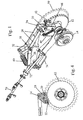
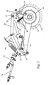
Fig. 1 is a perspective view of a reversing mechanism of the invention, -
Fig. 2 is a front view of the mechanism shown inFig. 1 , -
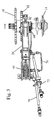
Fig. 3 is a plan view from above of the mechanism shown inFig. 1 , -
Fig. 4 is a section through a detail of the reversing mechanism ofFig. 1 , andFig. 5 is a schematic representation of the hydraulic circuit of the reversing mechanism inFig. 1 . - In the drawings, the
sprocket 10 is used to drive the rotor of a baler, the rotor not being shown in the drawings. Aratchet 12 is mounted on the same axis for rotation with the rotor as is asecond sprocket 14 which is used to transmit drive to a pickup. As earlier explained, blockages develop from time to time within the baler and these are freed by rotating the rotor in the reverse direction. - The present invention is concerned only with the reversing mechanism and only the parts concerned with driving the rotor in the reverse direction will now be described in detail.
- The reversing mechanism comprises a reversing
arm 16 rotatable about the axis of the rotor and carrying ahead 18 which is shown in section inFig. 4 . Thehead 18 can pivot relative to the reversingarm 16 about apivot bolt 20 and it carries apawl 22 which engages the teeth of theratchet 12. At apoint 24 above thepivot 20, thehead 18 is pivotably connected to the end of therod 30 of a double actinghydraulic jack 32 of which the cylinder is pivotably mounted about a fixedpivot bolt 34. - When the rotor is to be reversed for the purpose of clearing a blockage, the
rod 30 of thehydraulic jack 32 is retracted from the park position shown inFig. 2 . Pulling on thepivot point 24 causes of thehead 18 to pivot about thebolt 20 so that thepawl 22 engages in the teeth of theratchet 12. This locks the reversingarm 16 to the rotor and as therod 30 is retracted the rotor is caused to rotate in the reverse direction. To continue to turn the rotor after the rod of 30 has reached the limits of its stroke, therod 30 is first extended towards the illustrated position inFig. 2 . While doing so, thepawl 22 will ride over the teeth of theratchet 12 against the action of aspring 44 which biases thepawl 22 in a direction to engage with the ratchet teeth. Several cycles of operation of thehydraulic jack 32 may be carried out until the rotor has been turned sufficiently for the blockage to be cleared. - Once the blockage has been cleared, it is essential to ensure that the
pawl 22 has been disengaged from the teeth of theratchet 12 before the drive to the rotor through thesprocket 10 is re-engaged. This is effected by extending therod 30 to the position shown inFig. 2 in which the reversingarm 16 abuts anadjustable stop 42. Further extension of therod 30 will now cause thehead 18 to pivot clockwise, as viewed, about thebolt 20 and thereby disengage thepawl 22 from the teeth of theratchet 12. This is the position which is referred to herein as the park position. - As so far described the reversing mechanism and its method of operation are conventional. The problem that was encountered in the prior art was that the drive to the rotor could be engaged while the
pawl 22 was still engaged with the teeth of theratchet 12 with consequent damage to the reversing mechanism. - In the illustrated embodiment of the invention, the
head 18 of the reversing arm is additionally pivotably connected at thepoint 24 to a spring biased lever system that urges the reversingarm 16 towards the park position. The lever system comprises abell crank lever 26 which is itself pivoted at acentral fulcrum 38 about the free end of alever 28. Thelever 28 is pivoted about afixed axis 36 located near thepivot bolt 34. The end of one arm of the bell cranklever 26 is pivotably connected to thepoint 24 on thehead 18 of the reversingarm 16 while the free end of the other arm of the bell cranklever 28 is connected by way of acoil spring 40 to thepivot 36 of thelever 28. - Furthermore the circuit of the hydraulic jack is modified in the manner illustrated in
Fig. 5 . InFig. 5 , the parts of the hydraulic circuit shown to the left of the dottedline 50 form part of the tractor towing the baler. Twoconnectors position valve 56. Two ports on the input side of thevalve 56 are connected to ahydraulic pump 58 and areservoir 60, respectively. In the central position of the valve, as illustrated inFig, 5 , thepump 58 is connected to thereservoir 60 while both the output ports are blocked off. In one end position, the valve connects one of the output ports to thepump 58 and the other output port to thereservoir 60 while in the opposite end position these connections are reversed. - The
hydraulic jack 32 has two workingchambers rod 30, thepiston 66 acts as a differential piston and the cross sectional areas of the two workingchambers chamber 62 is connected by apipe 70 to theconnector 52 while the workingchamber 64 is connected by apipe 72 to theconnector 54. As so far described, the hydraulic circuit is conventional. In the illustrated embodiment of the invention there is an additional throttledpassage 74 that connects thepipe 72 to thepipe 70, the throttle being formed by a hole having a diameter of about 1.5 mm. - Starting from the position shown in the drawing, the
rod 30 is retracted by moving thevalve 56 to the first end position in which the workingchamber 64 is connected to thepump 58 and the larger working chamber is connected to thereservoir 60. In this position, fluid will also flow from thepump 58 to thereservoir 60 through the throttledpassage 74 but the size of the throttle ensures that sufficient pressure difference exists between the two working chambers to retract therod 30 and rotate the rotor in the reverse direction. - To return the
rod 30 to the park position, thevalve 56 is moved to the other end position to connect thepump 58 to the larger workingchamber 62 and the smaller workingchamber 62 to the reservoir. Once again, there will be some leakage through the throttledpassage 74 but despite this the return movement will be more rapid, because it will not be opposed by the rotor, because it will be assisted by thespring 40 and because the higher pressure of thepump 58 will be acting on the larger face of thepiston 66. - Let it now be assumed that the operator after having oscillated the valve between its two end positions to cause the rotor to reverse, inadvertently returns the valve to the central neutral position before the
rod 30 is fully retracted, i.e., while thepawl 22 is still engaged in the teeth of theratchet 12. In the prior art and in the absence of the throttledbypass passage 74, the rod would be hydraulically locked, but in the illustrated embodiment of the invention, even with the workingchambers valve 56 from thepump 58 and thereservoir 60, the rod is extended by the action of thespring 40. The force applied by thespring 40 is modified by thelever system rod 30 reaches the fully extended position. - During this movement of the piston, fluid displaced from the working
chamber 64 is pumped through thepassage 74 into the workingchamber 62 and as the latter has the larger cross sectional area hydraulic lock cannot occur because the increase in the volume of thechamber 62 will always exceed the decrease in the volume of the workingchamber 64. Any void that may appear in thechamber 62 as a result will contain a Torricellian vacuum but the force it generates is insignificant in comparison with the other forces acting on therod 30. - It would be possible to design the hydraulic jack so as to have working chambers of equal cross sectional area but this increases the cost of the jack unnecessarily.
Claims (6)
- A reversing mechanism for a rotor of an in-feed system of an agricultural harvesting machine, comprising a ratchet (12) mounted for rotation with the rotor, a pawl (22) carried by a reversing arm (16) for engaging the ratchet, a double acting hydraulic cylinder (32) for reciprocating the reversing arm to cause the rotor to rotate in a reverse direction, means (42) for disengaging the pawl from the ratchet when the reversing arm is in a park position, and a spring for urging the reversing arm towards the park position
characterised in that the working chambers (62, 64) of the double acting hydraulic cylinder (32) are permanently connected to one another by way of a throttled passage (74). - A reversing mechanism according to claim 1, characterised in that the hydraulic cylinder (32) has a differential piston (66), the pressure acting on the larger face of the piston being operable to move the reversing arm (16) towards the park position.
- A reversing mechanism according to claim 1 or 2, characterised in that the reversing arm (16) is mounted for rotation about the axis of the rotor and the pawl (22) is pivotably mounted on the reversing arm (16) in such a manner as to engage with the teeth of the ratchet (12) under the action of a further spring (44), the pawl being pivoted against the action of the further spring when it comes into a contact with a stationary abutment (42) in the park position of the reversing arm (16).
- A reversing mechanism according to any of the preceding claims, characterised in that the spring (40) urging the reversing arm (16) towards the park position acts on the reversing arm by way of a lever system (26, 28) designed to increase the spring force acting on the reversing arm as it approaches the park position.
- A reversing mechanism according to claim 4, characterised in that the lever system comprises a first lever (28) rotatable at one end about an axis (36) that is fixed in relation to the rotor axis and carrying at its opposite end a two-armed lever (26), one arm of the two-armed lever being connected to the reversing arm (16) and the other to the spring (40) urging the reversing arm towards the park position, the opposite end of the latter spring being anchored to a point (36) that is fixed relative to the axis of the rotor.
- A reversing mechanism according to claim 5, characterised in that the two-armed lever is a bell crank lever (26) and the anchoring point (36) of the spring (40) coincides with the pivot axis of the first lever (28).
Applications Claiming Priority (1)
| Application Number | Priority Date | Filing Date | Title |
|---|---|---|---|
| GB0607557A GB2437271A (en) | 2006-04-18 | 2006-04-18 | Rotor reversing mechanism |
Publications (2)
| Publication Number | Publication Date |
|---|---|
| EP1847170A1 EP1847170A1 (en) | 2007-10-24 |
| EP1847170B1 true EP1847170B1 (en) | 2008-12-31 |
Family
ID=36571869
Family Applications (1)
| Application Number | Title | Priority Date | Filing Date |
|---|---|---|---|
| EP07106331A Active EP1847170B1 (en) | 2006-04-18 | 2007-04-17 | Rotor reversing mechanism |
Country Status (5)
| Country | Link |
|---|---|
| US (1) | US7669400B2 (en) |
| EP (1) | EP1847170B1 (en) |
| AT (1) | ATE418855T1 (en) |
| DE (1) | DE602007000420D1 (en) |
| GB (1) | GB2437271A (en) |
Families Citing this family (5)
| Publication number | Priority date | Publication date | Assignee | Title |
|---|---|---|---|---|
| BE1020277A3 (en) * | 2011-10-17 | 2013-07-02 | Cnh Belgium Nv | REVERSE MECHANISM AND TRANSPORTATION DEVICES AND AGRICULTURAL BALER EQUIPPED FOR THEM. |
| US9374938B2 (en) | 2014-04-29 | 2016-06-28 | Dynamic Ditchers Inc. | Soil spreading scraper device |
| BE1024310B1 (en) * | 2016-06-22 | 2018-01-30 | Cnh Ind Belgium Nv | DEBLOCKER FOR A WORK MACHINE |
| US11589514B2 (en) * | 2019-10-30 | 2023-02-28 | Cnh Industrial America Llc | Pickup drive system for an agricultural baler |
| US11596105B2 (en) * | 2019-10-30 | 2023-03-07 | Cnh Industrial America Llc | Drive system for an agricultural baler |
Family Cites Families (9)
| Publication number | Priority date | Publication date | Assignee | Title |
|---|---|---|---|---|
| US3608557A (en) * | 1970-03-04 | 1971-09-28 | Case Co J I | Harvesting machine deslugging mechanism |
| US4296596A (en) * | 1979-03-29 | 1981-10-27 | Sperry Corporation | Automatic bale ejection drive |
| DE3336603A1 (en) | 1983-10-07 | 1985-04-25 | Klöckner-Humboldt-Deutz AG Zweigniederlassung Fahr, 7702 Gottmadingen | DEVICE FOR RETURNING THE INPUT SNAIL OF A COMBINE CUTTER |
| USRE32599E (en) * | 1983-12-12 | 1988-02-16 | New Holland Inc. | Drive reversing mechanism |
| DE19534138C1 (en) | 1995-09-14 | 1996-10-31 | Claas Ohg | Baling press for harvested crops, with receiving drum and cutter rotor |
| GB2313089A (en) * | 1996-05-14 | 1997-11-19 | Ford New Holland Nv | Baling, crop collecting and wrapping |
| DE20005965U1 (en) | 2000-03-31 | 2000-08-10 | Kverneland Gottmadingen Gmbh & | Cutting unit |
| US6681552B2 (en) * | 2001-02-02 | 2004-01-27 | Vermeer Manufacturing Company | Baler rotor reverser |
| US6644006B1 (en) * | 2002-07-19 | 2003-11-11 | New Holland North America, Inc. | Remote reverse control for pick-up rotor |
-
2006
- 2006-04-18 GB GB0607557A patent/GB2437271A/en not_active Withdrawn
-
2007
- 2007-04-16 US US11/787,277 patent/US7669400B2/en not_active Expired - Fee Related
- 2007-04-17 AT AT07106331T patent/ATE418855T1/en not_active IP Right Cessation
- 2007-04-17 DE DE602007000420T patent/DE602007000420D1/en active Active
- 2007-04-17 EP EP07106331A patent/EP1847170B1/en active Active
Also Published As
| Publication number | Publication date |
|---|---|
| GB0607557D0 (en) | 2006-05-24 |
| GB2437271A (en) | 2007-10-24 |
| US20070240398A1 (en) | 2007-10-18 |
| EP1847170A1 (en) | 2007-10-24 |
| ATE418855T1 (en) | 2009-01-15 |
| US7669400B2 (en) | 2010-03-02 |
| DE602007000420D1 (en) | 2009-02-12 |
Similar Documents
| Publication | Publication Date | Title |
|---|---|---|
| EP1847170B1 (en) | Rotor reversing mechanism | |
| EP2042028B1 (en) | Sequence and timing control for large round baler ejection device | |
| EP3275303B1 (en) | Harvesting machine | |
| US11172619B2 (en) | Agricultural baling machine clutch control | |
| EP3397043B1 (en) | Variable speed drive for large square baler | |
| EP3308630B1 (en) | Baler | |
| EP3818815A1 (en) | Agricultural baler | |
| US6681552B2 (en) | Baler rotor reverser | |
| US10881050B2 (en) | Baler stuffer selectively operable to provide partial stuffing strokes | |
| US20210251147A1 (en) | Agricultural baling machine | |
| US7942599B2 (en) | Coupling mechanism | |
| RU2488988C2 (en) | Agricultural piston press | |
| US20170181378A1 (en) | Improved Accumulator Circuit for Towed Implements | |
| US20210140359A1 (en) | Agricultural system | |
| US11871701B2 (en) | Baling machine including a drive-transferring driveline | |
| US6644005B1 (en) | Combination overload and overfill protection system for a round baler | |
| US5419086A (en) | Agricultural harvester | |
| BE1027694B1 (en) | Drive arrangement for an agricultural implement with mechanical overload clutch and automatic adjustment of the switch-off torque | |
| US20210137018A1 (en) | Agricultural system | |
| RU2267250C1 (en) | Grain combine | |
| SU757654A1 (en) | Limiter of traction effort of tractor with mounted soil-working equipment | |
| RU2241326C2 (en) | Grain combine |
Legal Events
| Date | Code | Title | Description |
|---|---|---|---|
| PUAI | Public reference made under article 153(3) epc to a published international application that has entered the european phase |
Free format text: ORIGINAL CODE: 0009012 |
|
| AK | Designated contracting states |
Kind code of ref document: A1 Designated state(s): AT BE BG CH CY CZ DE DK EE ES FI FR GB GR HU IE IS IT LI LT LU LV MC MT NL PL PT RO SE SI SK TR |
|
| AX | Request for extension of the european patent |
Extension state: AL BA HR MK YU |
|
| 17P | Request for examination filed |
Effective date: 20080424 |
|
| AKX | Designation fees paid |
Designated state(s): AT BE BG CH CY CZ DE DK EE ES FI FR GB GR HU IE IS IT LI LT LU LV MC MT NL PL PT RO SE SI SK TR |
|
| GRAP | Despatch of communication of intention to grant a patent |
Free format text: ORIGINAL CODE: EPIDOSNIGR1 |
|
| GRAS | Grant fee paid |
Free format text: ORIGINAL CODE: EPIDOSNIGR3 |
|
| GRAA | (expected) grant |
Free format text: ORIGINAL CODE: 0009210 |
|
| AK | Designated contracting states |
Kind code of ref document: B1 Designated state(s): AT BE BG CH CY CZ DE DK EE ES FI FR GB GR HU IE IS IT LI LT LU LV MC MT NL PL PT RO SE SI SK TR |
|
| REG | Reference to a national code |
Ref country code: CH Ref legal event code: EP Ref country code: GB Ref legal event code: FG4D |
|
| REF | Corresponds to: |
Ref document number: 602007000420 Country of ref document: DE Date of ref document: 20090212 Kind code of ref document: P |
|
| REG | Reference to a national code |
Ref country code: IE Ref legal event code: FG4D |
|
| PG25 | Lapsed in a contracting state [announced via postgrant information from national office to epo] |
Ref country code: PL Free format text: LAPSE BECAUSE OF FAILURE TO SUBMIT A TRANSLATION OF THE DESCRIPTION OR TO PAY THE FEE WITHIN THE PRESCRIBED TIME-LIMIT Effective date: 20081231 Ref country code: LV Free format text: LAPSE BECAUSE OF FAILURE TO SUBMIT A TRANSLATION OF THE DESCRIPTION OR TO PAY THE FEE WITHIN THE PRESCRIBED TIME-LIMIT Effective date: 20081231 Ref country code: FI Free format text: LAPSE BECAUSE OF FAILURE TO SUBMIT A TRANSLATION OF THE DESCRIPTION OR TO PAY THE FEE WITHIN THE PRESCRIBED TIME-LIMIT Effective date: 20081231 Ref country code: SI Free format text: LAPSE BECAUSE OF FAILURE TO SUBMIT A TRANSLATION OF THE DESCRIPTION OR TO PAY THE FEE WITHIN THE PRESCRIBED TIME-LIMIT Effective date: 20081231 |
|
| PG25 | Lapsed in a contracting state [announced via postgrant information from national office to epo] |
Ref country code: LT Free format text: LAPSE BECAUSE OF FAILURE TO SUBMIT A TRANSLATION OF THE DESCRIPTION OR TO PAY THE FEE WITHIN THE PRESCRIBED TIME-LIMIT Effective date: 20081231 Ref country code: ES Free format text: LAPSE BECAUSE OF FAILURE TO SUBMIT A TRANSLATION OF THE DESCRIPTION OR TO PAY THE FEE WITHIN THE PRESCRIBED TIME-LIMIT Effective date: 20090411 Ref country code: EE Free format text: LAPSE BECAUSE OF FAILURE TO SUBMIT A TRANSLATION OF THE DESCRIPTION OR TO PAY THE FEE WITHIN THE PRESCRIBED TIME-LIMIT Effective date: 20081231 Ref country code: RO Free format text: LAPSE BECAUSE OF FAILURE TO SUBMIT A TRANSLATION OF THE DESCRIPTION OR TO PAY THE FEE WITHIN THE PRESCRIBED TIME-LIMIT Effective date: 20081231 |
|
| PG25 | Lapsed in a contracting state [announced via postgrant information from national office to epo] |
Ref country code: PT Free format text: LAPSE BECAUSE OF FAILURE TO SUBMIT A TRANSLATION OF THE DESCRIPTION OR TO PAY THE FEE WITHIN THE PRESCRIBED TIME-LIMIT Effective date: 20090601 Ref country code: AT Free format text: LAPSE BECAUSE OF FAILURE TO SUBMIT A TRANSLATION OF THE DESCRIPTION OR TO PAY THE FEE WITHIN THE PRESCRIBED TIME-LIMIT Effective date: 20081231 Ref country code: CZ Free format text: LAPSE BECAUSE OF FAILURE TO SUBMIT A TRANSLATION OF THE DESCRIPTION OR TO PAY THE FEE WITHIN THE PRESCRIBED TIME-LIMIT Effective date: 20081231 Ref country code: IS Free format text: LAPSE BECAUSE OF FAILURE TO SUBMIT A TRANSLATION OF THE DESCRIPTION OR TO PAY THE FEE WITHIN THE PRESCRIBED TIME-LIMIT Effective date: 20090430 Ref country code: SE Free format text: LAPSE BECAUSE OF FAILURE TO SUBMIT A TRANSLATION OF THE DESCRIPTION OR TO PAY THE FEE WITHIN THE PRESCRIBED TIME-LIMIT Effective date: 20090331 |
|
| PG25 | Lapsed in a contracting state [announced via postgrant information from national office to epo] |
Ref country code: SK Free format text: LAPSE BECAUSE OF FAILURE TO SUBMIT A TRANSLATION OF THE DESCRIPTION OR TO PAY THE FEE WITHIN THE PRESCRIBED TIME-LIMIT Effective date: 20081231 |
|
| PG25 | Lapsed in a contracting state [announced via postgrant information from national office to epo] |
Ref country code: DK Free format text: LAPSE BECAUSE OF FAILURE TO SUBMIT A TRANSLATION OF THE DESCRIPTION OR TO PAY THE FEE WITHIN THE PRESCRIBED TIME-LIMIT Effective date: 20081231 |
|
| PLBE | No opposition filed within time limit |
Free format text: ORIGINAL CODE: 0009261 |
|
| STAA | Information on the status of an ep patent application or granted ep patent |
Free format text: STATUS: NO OPPOSITION FILED WITHIN TIME LIMIT |
|
| 26N | No opposition filed |
Effective date: 20091001 |
|
| PG25 | Lapsed in a contracting state [announced via postgrant information from national office to epo] |
Ref country code: BG Free format text: LAPSE BECAUSE OF FAILURE TO SUBMIT A TRANSLATION OF THE DESCRIPTION OR TO PAY THE FEE WITHIN THE PRESCRIBED TIME-LIMIT Effective date: 20090331 |
|
| REG | Reference to a national code |
Ref country code: IE Ref legal event code: MM4A |
|
| PG25 | Lapsed in a contracting state [announced via postgrant information from national office to epo] |
Ref country code: IE Free format text: LAPSE BECAUSE OF NON-PAYMENT OF DUE FEES Effective date: 20090417 Ref country code: MC Free format text: LAPSE BECAUSE OF NON-PAYMENT OF DUE FEES Effective date: 20090430 |
|
| PG25 | Lapsed in a contracting state [announced via postgrant information from national office to epo] |
Ref country code: GR Free format text: LAPSE BECAUSE OF FAILURE TO SUBMIT A TRANSLATION OF THE DESCRIPTION OR TO PAY THE FEE WITHIN THE PRESCRIBED TIME-LIMIT Effective date: 20090401 |
|
| PG25 | Lapsed in a contracting state [announced via postgrant information from national office to epo] |
Ref country code: IT Free format text: LAPSE BECAUSE OF NON-PAYMENT OF DUE FEES Effective date: 20100417 |
|
| PG25 | Lapsed in a contracting state [announced via postgrant information from national office to epo] |
Ref country code: LU Free format text: LAPSE BECAUSE OF NON-PAYMENT OF DUE FEES Effective date: 20090417 |
|
| PG25 | Lapsed in a contracting state [announced via postgrant information from national office to epo] |
Ref country code: HU Free format text: LAPSE BECAUSE OF FAILURE TO SUBMIT A TRANSLATION OF THE DESCRIPTION OR TO PAY THE FEE WITHIN THE PRESCRIBED TIME-LIMIT Effective date: 20090701 |
|
| PG25 | Lapsed in a contracting state [announced via postgrant information from national office to epo] |
Ref country code: TR Free format text: LAPSE BECAUSE OF FAILURE TO SUBMIT A TRANSLATION OF THE DESCRIPTION OR TO PAY THE FEE WITHIN THE PRESCRIBED TIME-LIMIT Effective date: 20081231 |
|
| PG25 | Lapsed in a contracting state [announced via postgrant information from national office to epo] |
Ref country code: CY Free format text: LAPSE BECAUSE OF FAILURE TO SUBMIT A TRANSLATION OF THE DESCRIPTION OR TO PAY THE FEE WITHIN THE PRESCRIBED TIME-LIMIT Effective date: 20081231 |
|
| REG | Reference to a national code |
Ref country code: CH Ref legal event code: PL |
|
| PG25 | Lapsed in a contracting state [announced via postgrant information from national office to epo] |
Ref country code: CH Free format text: LAPSE BECAUSE OF NON-PAYMENT OF DUE FEES Effective date: 20110430 Ref country code: LI Free format text: LAPSE BECAUSE OF NON-PAYMENT OF DUE FEES Effective date: 20110430 |
|
| REG | Reference to a national code |
Ref country code: DE Ref legal event code: R082 Ref document number: 602007000420 Country of ref document: DE Representative=s name: PATENTANWAELTE WALLACH, KOCH & PARTNER, DE |
|
| REG | Reference to a national code |
Ref country code: DE Ref legal event code: R081 Ref document number: 602007000420 Country of ref document: DE Owner name: CNH INDUSTRIAL BELGIUM NV, BE Free format text: FORMER OWNER: CNH BELGIUM NV, ZEDELGEM, BE Effective date: 20140428 Ref country code: DE Ref legal event code: R082 Ref document number: 602007000420 Country of ref document: DE Representative=s name: PATENTANWAELTE WALLACH, KOCH & PARTNER, DE Effective date: 20140428 Ref country code: DE Ref legal event code: R082 Ref document number: 602007000420 Country of ref document: DE Representative=s name: PATENTANWAELTE WALLACH, KOCH, DR. HAIBACH, FEL, DE Effective date: 20140428 |
|
| REG | Reference to a national code |
Ref country code: FR Ref legal event code: CD Owner name: CNH INDUSTRIAL BELGIUM NV Effective date: 20140725 |
|
| REG | Reference to a national code |
Ref country code: NL Ref legal event code: TD Effective date: 20150714 |
|
| REG | Reference to a national code |
Ref country code: NL Ref legal event code: TD Effective date: 20150714 |
|
| REG | Reference to a national code |
Ref country code: FR Ref legal event code: PLFP Year of fee payment: 10 |
|
| REG | Reference to a national code |
Ref country code: FR Ref legal event code: PLFP Year of fee payment: 11 |
|
| PGFP | Annual fee paid to national office [announced via postgrant information from national office to epo] |
Ref country code: GB Payment date: 20170413 Year of fee payment: 11 |
|
| REG | Reference to a national code |
Ref country code: FR Ref legal event code: PLFP Year of fee payment: 12 |
|
| PGFP | Annual fee paid to national office [announced via postgrant information from national office to epo] |
Ref country code: NL Payment date: 20180427 Year of fee payment: 12 |
|
| PGFP | Annual fee paid to national office [announced via postgrant information from national office to epo] |
Ref country code: IT Payment date: 20180405 Year of fee payment: 12 |
|
| GBPC | Gb: european patent ceased through non-payment of renewal fee |
Effective date: 20180417 |
|
| PG25 | Lapsed in a contracting state [announced via postgrant information from national office to epo] |
Ref country code: GB Free format text: LAPSE BECAUSE OF NON-PAYMENT OF DUE FEES Effective date: 20180417 |
|
| PGFP | Annual fee paid to national office [announced via postgrant information from national office to epo] |
Ref country code: BE Payment date: 20190408 Year of fee payment: 13 |
|
| REG | Reference to a national code |
Ref country code: NL Ref legal event code: MM Effective date: 20190501 |
|
| PG25 | Lapsed in a contracting state [announced via postgrant information from national office to epo] |
Ref country code: NL Free format text: LAPSE BECAUSE OF NON-PAYMENT OF DUE FEES Effective date: 20190501 |
|
| PG25 | Lapsed in a contracting state [announced via postgrant information from national office to epo] |
Ref country code: IT Free format text: LAPSE BECAUSE OF NON-PAYMENT OF DUE FEES Effective date: 20190417 |
|
| REG | Reference to a national code |
Ref country code: DE Ref legal event code: R082 Ref document number: 602007000420 Country of ref document: DE Representative=s name: MEISSNER BOLTE PATENTANWAELTE RECHTSANWAELTE P, DE |
|
| PGFP | Annual fee paid to national office [announced via postgrant information from national office to epo] |
Ref country code: FR Payment date: 20200420 Year of fee payment: 14 |
|
| REG | Reference to a national code |
Ref country code: BE Ref legal event code: MM Effective date: 20200430 |
|
| PG25 | Lapsed in a contracting state [announced via postgrant information from national office to epo] |
Ref country code: BE Free format text: LAPSE BECAUSE OF NON-PAYMENT OF DUE FEES Effective date: 20200430 |
|
| REG | Reference to a national code |
Ref country code: DE Ref legal event code: R084 Ref document number: 602007000420 Country of ref document: DE |
|
| PG25 | Lapsed in a contracting state [announced via postgrant information from national office to epo] |
Ref country code: FR Free format text: LAPSE BECAUSE OF NON-PAYMENT OF DUE FEES Effective date: 20210430 |
|
| PGFP | Annual fee paid to national office [announced via postgrant information from national office to epo] |
Ref country code: DE Payment date: 20230426 Year of fee payment: 17 |