EP1845755A2 - Systèmes d'illumination - Google Patents
Systèmes d'illumination Download PDFInfo
- Publication number
- EP1845755A2 EP1845755A2 EP07007358A EP07007358A EP1845755A2 EP 1845755 A2 EP1845755 A2 EP 1845755A2 EP 07007358 A EP07007358 A EP 07007358A EP 07007358 A EP07007358 A EP 07007358A EP 1845755 A2 EP1845755 A2 EP 1845755A2
- Authority
- EP
- European Patent Office
- Prior art keywords
- wire
- illumination
- illumination system
- current
- power supply
- Prior art date
- Legal status (The legal status is an assumption and is not a legal conclusion. Google has not performed a legal analysis and makes no representation as to the accuracy of the status listed.)
- Withdrawn
Links
Images


Classifications
-
- H—ELECTRICITY
- H05—ELECTRIC TECHNIQUES NOT OTHERWISE PROVIDED FOR
- H05B—ELECTRIC HEATING; ELECTRIC LIGHT SOURCES NOT OTHERWISE PROVIDED FOR; CIRCUIT ARRANGEMENTS FOR ELECTRIC LIGHT SOURCES, IN GENERAL
- H05B45/00—Circuit arrangements for operating light-emitting diodes [LED]
- H05B45/50—Circuit arrangements for operating light-emitting diodes [LED] responsive to malfunctions or undesirable behaviour of LEDs; responsive to LED life; Protective circuits
- H05B45/58—Circuit arrangements for operating light-emitting diodes [LED] responsive to malfunctions or undesirable behaviour of LEDs; responsive to LED life; Protective circuits involving end of life detection of LEDs
-
- H—ELECTRICITY
- H02—GENERATION; CONVERSION OR DISTRIBUTION OF ELECTRIC POWER
- H02J—CIRCUIT ARRANGEMENTS OR SYSTEMS FOR SUPPLYING OR DISTRIBUTING ELECTRIC POWER; SYSTEMS FOR STORING ELECTRIC ENERGY
- H02J50/00—Circuit arrangements or systems for wireless supply or distribution of electric power
- H02J50/10—Circuit arrangements or systems for wireless supply or distribution of electric power using inductive coupling
- H02J50/12—Circuit arrangements or systems for wireless supply or distribution of electric power using inductive coupling of the resonant type
-
- H—ELECTRICITY
- H02—GENERATION; CONVERSION OR DISTRIBUTION OF ELECTRIC POWER
- H02J—CIRCUIT ARRANGEMENTS OR SYSTEMS FOR SUPPLYING OR DISTRIBUTING ELECTRIC POWER; SYSTEMS FOR STORING ELECTRIC ENERGY
- H02J50/00—Circuit arrangements or systems for wireless supply or distribution of electric power
- H02J50/40—Circuit arrangements or systems for wireless supply or distribution of electric power using two or more transmitting or receiving devices
- H02J50/402—Circuit arrangements or systems for wireless supply or distribution of electric power using two or more transmitting or receiving devices the two or more transmitting or the two or more receiving devices being integrated in the same unit, e.g. power mats with several coils or antennas with several sub-antennas
-
- H—ELECTRICITY
- H05—ELECTRIC TECHNIQUES NOT OTHERWISE PROVIDED FOR
- H05B—ELECTRIC HEATING; ELECTRIC LIGHT SOURCES NOT OTHERWISE PROVIDED FOR; CIRCUIT ARRANGEMENTS FOR ELECTRIC LIGHT SOURCES, IN GENERAL
- H05B45/00—Circuit arrangements for operating light-emitting diodes [LED]
- H05B45/30—Driver circuits
- H05B45/37—Converter circuits
- H05B45/3725—Switched mode power supply [SMPS]
- H05B45/39—Circuits containing inverter bridges
-
- H—ELECTRICITY
- H05—ELECTRIC TECHNIQUES NOT OTHERWISE PROVIDED FOR
- H05B—ELECTRIC HEATING; ELECTRIC LIGHT SOURCES NOT OTHERWISE PROVIDED FOR; CIRCUIT ARRANGEMENTS FOR ELECTRIC LIGHT SOURCES, IN GENERAL
- H05B45/00—Circuit arrangements for operating light-emitting diodes [LED]
- H05B45/30—Driver circuits
- H05B45/395—Linear regulators
-
- H—ELECTRICITY
- H02—GENERATION; CONVERSION OR DISTRIBUTION OF ELECTRIC POWER
- H02J—CIRCUIT ARRANGEMENTS OR SYSTEMS FOR SUPPLYING OR DISTRIBUTING ELECTRIC POWER; SYSTEMS FOR STORING ELECTRIC ENERGY
- H02J50/00—Circuit arrangements or systems for wireless supply or distribution of electric power
- H02J50/005—Mechanical details of housing or structure aiming to accommodate the power transfer means, e.g. mechanical integration of coils, antennas or transducers into emitting or receiving devices
-
- H—ELECTRICITY
- H05—ELECTRIC TECHNIQUES NOT OTHERWISE PROVIDED FOR
- H05B—ELECTRIC HEATING; ELECTRIC LIGHT SOURCES NOT OTHERWISE PROVIDED FOR; CIRCUIT ARRANGEMENTS FOR ELECTRIC LIGHT SOURCES, IN GENERAL
- H05B45/00—Circuit arrangements for operating light-emitting diodes [LED]
- H05B45/30—Driver circuits
- H05B45/355—Power factor correction [PFC]; Reactive power compensation
-
- Y—GENERAL TAGGING OF NEW TECHNOLOGICAL DEVELOPMENTS; GENERAL TAGGING OF CROSS-SECTIONAL TECHNOLOGIES SPANNING OVER SEVERAL SECTIONS OF THE IPC; TECHNICAL SUBJECTS COVERED BY FORMER USPC CROSS-REFERENCE ART COLLECTIONS [XRACs] AND DIGESTS
- Y02—TECHNOLOGIES OR APPLICATIONS FOR MITIGATION OR ADAPTATION AGAINST CLIMATE CHANGE
- Y02B—CLIMATE CHANGE MITIGATION TECHNOLOGIES RELATED TO BUILDINGS, e.g. HOUSING, HOUSE APPLIANCES OR RELATED END-USER APPLICATIONS
- Y02B20/00—Energy efficient lighting technologies, e.g. halogen lamps or gas discharge lamps
- Y02B20/30—Semiconductor lamps, e.g. solid state lamps [SSL] light emitting diodes [LED] or organic LED [OLED]
Definitions
- the present invention relates to illumination systems and methods, and more particularly, to illumination systems and methods for general lighting and commercial signs.
- Channel letters generally include a housing with a concave cross-section about 5" deep, made of aluminum or plastic.
- the housing cavity, shaped as the letter, is covered by a translucent plastic sheet of a selected color, illuminated by a light source mounted within.
- Neon and fluorescent lights provide suitable illumination, allowing the letters to shine brightly when turned on.
- fluorescent light sources have a relatively short life of approximately 20,000 hours. They operate at high voltage (for example, 7,000 to 15,000 volts for neon) and can consume a relatively large amount of electrical power.
- fluorescent light tubes are usually quite fragile. Still, fluorescent lights have been used for decades and decades in different fields.
- LEDs Light emitting diodes
- LEDs are currently used for a wide range of applications, providing a variety of advantages relative to conventional lights, such as neon or fluorescent bulbs, due to their advantageous qualities. LEDs are compact, rugged, and consume less power, being 30 to 70% more energy efficient than conventional lights. LEDs have a relatively long life of up to 100,000 hours and operate at low voltages (4 VDC to 24 VDC).
- Fig. 1 shows an example of an illuminating system as used presently for general lighting and commercial sign lighting systems.
- the illumination system includes a DC power supply usually connected to 120 VAC.
- the output from the power supply provides DC voltage (from 4 to 24 VDC) to a supply rail providing electrical connection to LED arrays arranged in several illumination modules. These modules are usually connected in parallel on a DC supply bus.
- the LEDs are connected with wires that are soldered permanently at a fixed spacing; that is, use fixed electrical wiring. Every single illumination module is connected to the next module using two or four wires ( i.e., positive and negative inputs and outputs) by mechanically creating electrical contact.
- Each LED module uses a ballast resistor R (or regulator) to provide a constant current to the LEDs connected in series since LEDs operate with current (and not voltage).
- the modules are usually located inside a letter channel.
- This dissipative method normally uses as much energy in the ballast resistor (i.e., dissipated energy) as in the LEDs, resulting in efficiencies frequently lower than 50%. This means there is more energy wasted in heat than energy used by the LEDs to produce light.
- the brightness of an LED depends upon the amount of electrical current flowing through the diode. However, while an increase in current increases the brightness of the light emitted by the LED, it also increases the connection temperature, which can decrease the LED's efficiency and life. Given that LEDs are often constructed of semiconductor materials that share many comparable properties with silicone and gallium arsenide, this can be highly detrimental. As a case in point, for every 10°C increase in temperature, the useful life of silicone and gallium arsenide drops 2.5-3 times.
- the conventional light circuits can be prone to problems other than those described above.
- the system of Fig. 1 includes modules joined with connectors, which are prone to reliability troubles.
- connectors can fail due to corrosion, and many devices, as well as commercial lighting systems, are used outdoors.
- diodes are generally biased through a series resistor from a regulated voltage supply, the amount of current going through the diode depends also on the forward voltage drop over the diode, which drops with changes in its size, age, and its temperature at the time.
- the LEDs have been also used as light sources in applications such as emergency EXIT signs.
- the EXIT signs contain a reflector in the rear, having a series of curved, concave surfaces shaped as letters and background area.
- the LEDs are mounted in the center of each surface to provide light that is projected outwardly.
- LED-illuminated channel letters are now available from companies such as Lektron or LumiLEDs, Inc. (part numbers HLCR-KR-R0100 and HCLR-KR99-R0200).
- the LED lighting systems generally consist of a housing with a printed circuit board comprised of a thin dielectric sheet and a plurality of electrically-conductive contacts on one side of the sheet. Each contact is configured to mount a lead of one or more LEDs, so that the LEDs are connected in series.
- the chain of LEDs is mounted onto a bendable rail, which is attached to the circuit board within the housing.
- a translucent sheet covers the LEDs within the housing.
- the letters use an AC/DC mother power supply and a DC/DC daughter power supply.
- a heat conductive plate is found on the other side of the dielectric sheet.
- the plate touches the contacts through the dielectric sheet.
- the first side of the plate has a surface area substantially larger than a contact area between the contacts and the dielectric sheet.
- the plate has a second side adapted to provide thermal contact with a heat-conducting surface to encourage heat transfer from the LEDs to the heat-conducting surface and try to prevent overheating of the connections.
- the present invention relates to illumination systems and methods for general lighting and commercial signs.
- the illumination system includes a master power supply providing power to several illumination modules.
- the master power supply is constructed and arranged to generate high-frequency and low-voltage electrical power provided to a primary wire forming a current loop.
- Each illumination module includes an electromagnetic coupling element and several light sources.
- the electromagnetic coupling element includes a magnetic core arranged to receive the current loop in a removable arrangement, and a secondary wire wound around the magnetic core to enable inductive coupling.
- the secondary wire is connected to provide current to the light sources.
- the magnetic core and a part of the secondary wire wound around the core are encapsulated, thereby sealing the core and wire portion while enabling displacement of the primary wire with respect to the encapsulated ferromagnetic core.
- the magnetic core may be made of a ferromagnetic material, a ferrite, or a soft ferrite.
- the magnetic core is ring-shaped and the secondary wire is wound around at least a portion of the ring-shaped core.
- the primary wire is threaded through an opening in the ring-shaped core.
- the illumination system includes low voltage or medium voltages light sources.
- the illumination system includes light emitting diodes or incandescent lights.
- the magnetic core has a rectangular shape
- the secondary wire is wound around at least a portion of the rectangularly-shaped core.
- the primary wire is threaded through an opening in the rectangularly-shaped core.
- the illumination system includes light sources that are preferably light emitting diodes (LEDs).
- the magnetic core is shaped to include a closed magnetic path, and wherein the secondary wire is wound around at least a portion of the core to provide electromagnetic coupling.
- the primary wire is located inside the core and arranged to provide electromagnetic coupling.
- the illumination system includes a master power supply that includes a resonant inverter.
- the inverter provides an output in the range of about 20 kHz to about 40 kHz.
- the master power supply includes a self-oscillating inverter providing substantially a sine wave output.
- an electromagnetic coupling element is used with an illumination system.
- the coupling element is constructed to couple inductively power from a power supply to one or multiple light sources.
- the coupling element includes a magnetic core, a source wire wound around at least a portion of the magnetic core and being connected to at least one light source, and a casing surrounding the magnetic core and the source wire at the portion being wound around the magnetic core to electrically insulate the source wire and the magnetic core.
- the coupling element also includes an inductive region defined by the magnetic core and arranged to receive a conductor in a removable arrangement with respect to the magnetic core, the conductor being located to couple inductively power from a power supply to the source wire.
- a master power supply is designed for an illumination system.
- the master power supply includes a resonant inverter, an AC current source, and a transformer.
- the resonant inverter is constructed and arranged to generate a high-frequency and low-voltage electrical output.
- the AC current source includes an inductor connected to receive the electrical output.
- the transformer has a primary side and a secondary side, wherein the primary side is connected to the current source and the secondary side is arranged to provide current to an illumination module that includes several light emitting diodes (LEDs).
- LEDs light emitting diodes
- the master power supply includes a microcontroller.
- the master power supply can include a power factor corrector, a pulse width modulation (PWM) line regulator a loop current sensor, or an open circuit voltage sensor.
- PWM pulse width modulation
- an illumination method includes generating high-frequency and low-voltage electrical power; providing the high-frequency and low-voltage electrical power to a primary wire forming a current loop; coupling energy from the current loop in a contactless manner to a secondary wire; and delivering current from the secondary wire to several light emitting diodes (LEDs).
- LEDs light emitting diodes
- the illumination method includes controlling the high-frequency and low-voltage electrical power, and/or sensing a loop current by monitoring output of the high-frequency and low-voltage electrical signal, and/or sensing an open voltage current.
- an installation method for contactless coupling one or several illumination modules to a power supply.
- the illumination system comprises a master power supply constructed and arranged to provide electrical power to a primary wire forming a current loop; and an illumination module including an electromagnetic coupling element and several light sources.
- the electromagnetic coupling element includes a magnetic core.
- the method includes positioning one or several of the illumination modules constructed to provide light; and positioning the primary wire in a close proximity to the illumination module without establishing an electrical connection, the positioning enabling inductive power transfer from the primary wire to a secondary wire wound around at least a portion of the ferromagnetic core, wherein the secondary wire is connected to provide current to one or multiple light sources.
- the described illumination system has numerous advantages: There is no need to establish electrical contact or connection to any of the illumination modules, thus increased reliability, lower cost, not position dependent.
- the system has high efficiency (relatively low power consumption by the elimination of the ballast resistor used for LEDs in prior art systems.
- Quick and easy installation since there is no polarity because of using alternating current provided by the master power supply.
- the system can be truly waterproof when the illumination module is encapsulated since there is no connection to the outside world. This provides greater installation safety due to the absence of voltage nearby which prevents accidental contact, and since there is no touchable connection or soldering accessible.
- Illumination system 100 includes a high frequency power supply 102 powered by a power line 101 (for example, 110V and 50 Hz or 220 V and 60Hz).
- High frequency power supply 102 includes a high frequency (HF) inverter 105 and a current source 108 including a current limiter 110.
- HF inverter 105 provides a sinusoidal signal of a frequency in the range of 5 kHz to 100 kHz, and preferably in the range of 20 kHz to 40 kHz to transformer T.
- the output from illumination system 100 is provided to a primary current loop 114.
- Several illumination modules 120, 120A, 120B ...120N are coupled to illumination system 100 using current loop 114.
- Each illumination module 120 includes an electromagnetic coupling element (shown in detail in Fig. 4B and also shown in Figs. 2, 2A and 4A) and several light sources that are preferably light emitting diodes (LEDs). In general, the light sources are low voltage or medium voltage light sources.
- electromagnetic coupling element shown in detail in Fig. 4B and also shown in Figs. 2, 2A and 4A
- LEDs light emitting diodes
- the light sources are low voltage or medium voltage light sources.
- illumination module 120 includes the electromagnetic coupling element with a primary wire 114 and a secondary wire 121 inductively coupled together using a magnetic element 124 (preferably made of a ferrite material).
- Secondary wire 121 is connected to an AD to DC converted 126 providing power to LEDs 130, 130A and 130B; that is a DC load 124.
- Electromagnetic coupling element 232 (shown in Fig. 4B) includes a secondary wire 121 (162 in Fig. 4B) wound around ferrite core 124 (164 in Fig. 4B) to form a coil, wherein secondary wire 121 is electrically connected to provide current to light sources 130.
- Ferrite core 164 is constructed and arranged to receive current loop 114 inside the corresponding magnetic path in a removable arrangement.
- this enables easy and convenient assembly of several illumination modules, for example inside a letter channel.
- several LEDs are connected together.
- the absence of a ballast resistor connected to the LEDs increases the efficiency (which may be even greater than 95%) obtained from the input power for the light source to produce light.
- electromagnetic coupling element 232 is preferably a sealed unit having the secondary wire wound around the ferrite core, with both the secondary wire and the ferrite core sealed in a water resistant manner.
- Electromagnetic coupling element 232 couples the electric power from primary wire 114 to secondary wire 121 (Fig. 2A) by induction as expressed in Faraday's law. That is, the AC current in primary wire 114 induces a voltage in coil 121 of the secondary wire, which provides electrical power delivered to the light sources.
- the secondary current is equal to the primary current divided by number of turns.
- primary wire 114 is electromagnetically coupled (i.e., "proximity coupled") to several secondary wires by the contactless electromagnetic coupling element, and thus primary wire 114 induces a voltage in several secondary coils wound around the ferrite cores.
- the output of electromagnetic coupling element 232 provides a true current source coupled to secondary wire 121. While current loop wire 114 (i.e., the primary wire) is preferably located inside the ferromagnetic core within the magnetic flux loop, other positions and geometries with respect to the ferrite core may be used as long as sufficient inductive coupling occurs.
- high frequency power supply 102 includes a rectifier (a bridge, or a DC source) connected to a high-frequency inverter 105, which is in turn connected to a primary side of a transformer T1.
- the high-frequency inverter uses a sinusoidal resonant circuit topology with two bipolar transistors Q1 and Q2.
- the collectors of transistors Q1 and Q2 are connected to the primary coil of transistor T1.
- the two transistors are turned ON and OFF and are arranged to provide a high current gain.
- the oscillation frequency depends on the capacitance of a capacitor C1 and the inductance of primary coils of transformer T1, having capacitor C1 connected across the primary winding.
- the auxiliary winding of transformer T1 is used to drive the bases of transistors Q1 and Q2.
- the secondary side T1C includes preferably one inductor (L2, L3 ... Ln) for each current loop.
- the inductor converts the output voltage of transformer T1 (in the secondary side T1 C) into an AC current source.
- Each current loop is connected to a connector 111 (or connectors 111A, 111 B...111 N), in an arrangement that has a single current loop providing power to one or several illumination modules.
- the secondary side T1 C provides several separate current sources.
- Each current source is provided from the secondary side of transformer T1, wherein the separate current loops are each connected to connectors 111A, 111B, 111C... 111 N.
- the inductor i.e., one of inductors L2, L3, L4 ... LN
- the inductor converts the output voltage of transformer T1 (secondary side T1 C) into an AC current source connected to one of the respective connectors 111A, 111B, 111C... 111 N.
- Inductors L2, L3, L4 ... LN form current limiters for the respective current loops.
- Each current loop may be used for a separate set of illumination modules (120, 120A, 1208, 120C, ... 120N, as in Fig. 2) having, for example, different color LEDs.
- high frequency power supply can provide power to multicolor display having separate LED modules.
- the high-frequency inverter may use a sinusoidal resonant circuit topology with four bipolar transistors, arranged as two pairs of transistors, wherein in each pair the emitter of the first transistor drives the base of the second transistor (i.e., Darlington pair). These two pairs are turned ON and OFF to provide an oscillating current at a high current gain.
- the oscillation frequency depends on the capacitance of the capacitor connected across the primary coil and the inductance of primary coil of the transformer.
- the auxiliary winding of this transformer is used to drive the bases of the transistors.
- the inverter may also include two diodes connected to the collectors of the transistors (across the primary side) together with an inductor, connected between the two capacitors and the emitters of the transistors to allow fast power inverter to turn OFF at anytime during the 60 Hz sign wave.
- the two capacitors correct the power factor of the inductor.
- the output from AC output current source has a sine waveform at a frequency in the possible range of 10 kHz to100 kHz, or preferably in the range of 20 kHz to 40 kHz, and preferably 30 kHz, and the output voltage in the possible range of 10 Vac to 200 Vac or preferably in the range of 12 Vac to 24 Vac.
- the secondary wire 121 is connected to a rectifier 126, which receives the induced AC power and provides a DC current to a set of light emitting diodes 130.
- the light emitting diodes (LEDs) are located inside of a letter channel or are used for other illumination.
- Illumination system 150 includes a high frequency AC power supply 102 powered by a power line 101.
- HF power supply 102 includes HF inverter 105 and AC current source 108 with current limiter 110.
- the output from the high frequency AC power supply 102 is provided to primary current loop 114, providing in turn power to several illumination modules 160, 160A, 160B, 160C ... 160N.
- Each illumination module 160 includes an electromagnetic coupling element 232 (shown in Figs. 2A, 4A and 4B) and an AC load 168.
- electromagnetic coupling element 232 includes ferrite core 164 arranged to receive current loop 114 in a removable arrangement.
- Electromagnetic coupling element 232 (shown in detail in Fig. 4B) also includes a secondary wire 161 wound around ferrite core 164 to form a coil, wherein secondary wire 161 is connected to provide current to light sources 168. Electromagnetic coupling element 232 is preferably a sealed unit having the secondary wire wound around the ferrite core. The secondary output of electromagnetic coupling element 232 provides a true current source.
- the output from secondary wire 161 (i.e., connections 162A and 162B) provide AC current directly to LEDs 170 ... 172N, and 180 ... 180N.
- LEDs 170 ... 172N, and 180 ... 180N In this AC load, one half of the LEDs is powered on the positive cycle and the other half on the negative cycle.
- ballast resistor coupled to the LEDs, since the magnetic core winding generates a true current source.
- the absence of a ballast resistor connected to the LEDs increases the efficiency (which may be even greater than 95%) obtained from the input power for the light source to produce light.
- the LEDs may be replaced with incandescent lamps, electroluminescent devices, or other low-voltage to medium-voltage light sources.
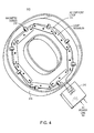
- Fig. 4 illustrates the illumination system of Fig. 3 used in a letter channel 218.
- the high-frequency AC voltage power supply 210 provides current to an AC current loop 114, which provides power to the individual illumination modules (shown as light strips) located in letter channel 218.
- Fig. 4A illustrates an illumination strip (or light module) located in letter channel 218.
- electromagnetic coupling element 232 shown in Fig. 4A provides contactless coupling to the illumination modules shown in Figs. 2, 3 or 4.
- Fig. 4C illustrates the illumination system utilizing a power supply shown in Fig. 2B and several illumination strips 230A, 230B, and 230C.
- Each illumination strips 230 can have different color light sources (for example, red, green or blue).
- the illumination strips may be controlled separately by controlling the current in the separate current loops 114A, 114B, and 114C (e.g., by employing a computerized control on each loop). This way, the illumination system can generate different light effects.
- Fig. 5 illustrates illumination system 150A also including a fault-sensing unit 152.
- Fault sensing unit 152 detects changes in voltage across current loop 114 at connectors 111A. The voltage changes (i.e., increase or decrease) are a signature of a fault in one of the illumination modules 160.
- Fault sensing unit 152 is connected to monitoring by a computer or telemetry to provide and store any faults in the illumination system 150 for later repair. Furthermore, fault sensing unit 152 may initiate an alarm signal.
- Fig. 5A illustrates a fault monitoring unit for use with illumination module 120 shown in Fig. 2A.
- the fault monitoring unit monitors the voltage across light sources 130, 130A ... and provides a fault signal injected into secondary wire 121. In the embodiment of Fig. 5A, this signal is injected on the AC side of illumination module 120. In general, the injected fault signal is then coupled from secondary wire 121 to current loop 114..
- Fault sensing unit 152 (Fig. 5) then detects the response to the injected signal and stores the fault.
- the injected signal can be coded (e.g., ripples of different size and duration) to identify the illumination module where the fault occurred.
- the above-described illumination systems may be used with different illumination modules including commercially available light sources.
- LED modules There are several different commercially available embodiments of the LED modules.
- Super White STP30XC Hi-Flux StripLED ® Modules may be used alone or connected to one another, enabling configuration of channel and reverse-channel letters, signs, and displays. These modules are available in lengths of 6, 12, and 24 in. strips, and feature 6, 12, and 24 Cool White 7,500 K Spider LEDs, respectively.
- Each module includes a double-ended connector harness for daisy-chain assembly, and a pre-applied strip of 3M ® double-sided foam tape for peel-and-stick placement.
- hi-flux, interconnectable StripLED ® LED modules may be used, which deliver high brightness and possess high flexibility.
- LEDtronics ® manufactures series STP30XC super white LED light strips that may be used alone or connected to one another, making it easy to configure lighting solutions for channel and reverse-channel letters, signs, displays, under-the-counter and architectural applications. These light strips are available in lengths of 6-inches, 12-inches and 24-inches, and they feature 6, 12 and 24 Cool White (7500K) LEDtronics SpiderLEDs, respectively.
- the STP306 is a 6-inch, 6 LED model that uses 0.72 Watts, emits 1.2fc and provides 29 lumens with a viewing angle of 85°.
- the STP324 is a 24-inch, 24 LED model that uses 2.88 Watts, emits 48fc and provides 115 lumens with a viewing angle of 85°.
- Each module has a double-ended connector harness for easy daisy-chain assembly, and a pre-applied strip of 3M ® double-sided foam tape for "peel and stick" placement.
- the Inter-Connector Module facilitates linking modules. One Inter-Connector module and one power adapter cable are included with each light strip purchased. In addition to channel-letter applications, Strip LED may be used in buildings, amusement parks, theaters, stairways, emergency exit pathway lighting, etc. These light strips eliminate many of the shortcomings of neon or fluorescent lamps such as heat, broken tubes and ballast failures.
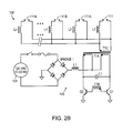
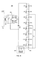
- Fig. 6 illustrates diagrammatically a high frequency power supply 250.
- HF power supply 250 includes a power factor corrector 254, a half bridge converter 256, an oscillator 258, and an AC current source 260 providing a sinusoidal output to current loop 114.
- Figs. 7, 7A and 7B show a schematic diagram of the high frequency power supply illustrated in Fig. 6. Referring to Fig. 7, the AC power input is provided to four SMA controlled avalanche rectifiers CR4, CR5, CR6, and CR7.
- Power factor corrector includes power factor correction controller U1 (FAN7527B made by Fairchild Semiconductor) and 400 V N-Channel MOSFET Q1 (FQP6N40C made by Fairchild Semiconductor). The regulated output of about 210 V DC is provided at capacitor C6 to half bridge converter 256.
- oscillator 258 includes four (4) dual 4-bit synchronous binary counters U3A, U3B, U5A, and U5B (74HC4520, made by Fairchild Semiconductor). Oscillator 258 preferably operates at 17 kHz.
- half bridge converter 256 includes two 300V N-channel MOSFETs Q2 and Q3 (FQP5N30 made by Fairchild Semiconductor) coupled to a half-bridge gate driver U4 (FAN7382M made by Fairchild Semiconductor).
- Half-bridge gate driver U4 receives input from oscillator 258.
- Current source 260 provides output via transformer 262 to current loop 114.
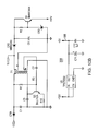
- Illumination module 280 includes an electromagnetic coupling element 282, AC to DC converter 284, a series of LEDs 286, and output 288 for diagnostic purposes.
- Electromagnetic coupling element 282 receives primary wire 114 (as coupling element 232 shown in Fig. 4B) and provides secondary wire output across capacitor C1 to AC to DC converter 284.
- AC to DC converter 284 includes four high-speed double diodes CR1, CR1a, CR2 and CR2a (BAV99 made by Philips Semiconductors).
- Strip 286 includes, for example 8 LEDs, each being coupled to a Zener diode. The Zener diodes provide electrical paths in case an individual LED fails so that the remaining LED can still operate.
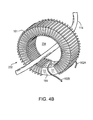
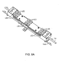
- Fig. 8A is a perspective view of an illumination module.
- the individual LEDs are mounted to provide a selected illumination angle (viewing angle) of the emitted light.
- Coupling element 232 is located inside the illumination module and wire 114 is threaded through the body of the module for contactless energy coupling.
- wire 114 is looped around back to the power supply (i.e., there is no return wire 114A).
- wire 114 is threaded through the module for contactless energy transfer and than the same wire provides the return (i.e., shown as wire 114A) nested next to the module, as shown in Fig. 8A.
- the LEDs may be mounted closer together for increased brightness.
- the current provided to LED may be automatically controlled by a microcontroller.
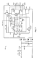
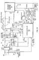
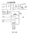
- Fig. 9 illustrates diagrammatically a high frequency power supply 300.
- HF power supply 300 includes an AC to DC converter 304, a line frequency sensor 306, a regulator 308, a pulse width modulator (PWM) line regulator 320, a microcontroller 310 receiving a voltage feedback 325 and a current feedback 329.
- P.W.M. line regulator 320 operates at 32 kHz and provides output to a current fed resonant inverter 340.
- Sine wave resonant inverter 340 receives an enable output 338 from microcontroller 310, and resonant inverter 340 provides a 16 kHz sinusoidal output 342 to a current source.
- a current sensor 350 is arranged in a feedback loop to provide an input to microcontroller 310 (MC68HC908QY4 made by Motorola Inc.). Furthermore, an open circuit voltage sensor 360 is connected across the output from resonant inverter 340 to signal open circuit condition to microcontroller 310.
- the AC current source provides a sinusoidal output to current loop 114 via transformer 370.
- Microcontroller 310 controls the max power output, the max output voltage, the loop current by software and registers the fault conditions of the illumination system.
- Figs. 10, 10A, 10B, 10C and 10D show a schematic diagram of the high frequency power supply 300.
- the 110V AC power input is provided to four SMA controlled avalanche rectifiers CR4, CR5, CR6, and CR7.
- Regulator 308 (shown in Fig. 10 B) includes two (2) NPN switching transistors Q1 and Q2 (MMBT3904 made by Philips Semiconductors), transformer T1 and a low-power low-dropout linear regulator U3( TPS76050 made by Texas Instruments).
- resonant inverter 340 has a sinusoidal resonant circuit topology that includes four PNP transistors Q7, Q9 Q10 and Q11 (MMBT4403).
- MMBT4403 PNP transistors
- two pairs of transistors Q9 + Q11 and Q7 + Q10) are connected so that in each pair the emitter of the first transistor drives the base of the second transistor (i.e., Darlington pair). These two pairs are turned ON and OFF via transformer T4 to provide an oscillating current at a high current gain.
- the 16 kHz output is provided to transformer T7 and to current sensor 350 and open circuit voltage sensor 360, as shown in Fig. 10D.
Landscapes
- Engineering & Computer Science (AREA)
- Computer Networks & Wireless Communication (AREA)
- Power Engineering (AREA)
- Circuit Arrangement For Electric Light Sources In General (AREA)
Applications Claiming Priority (1)
| Application Number | Priority Date | Filing Date | Title |
|---|---|---|---|
| US79062706P | 2006-04-10 | 2006-04-10 |
Publications (2)
| Publication Number | Publication Date |
|---|---|
| EP1845755A2 true EP1845755A2 (fr) | 2007-10-17 |
| EP1845755A3 EP1845755A3 (fr) | 2014-04-02 |
Family
ID=38229927
Family Applications (1)
| Application Number | Title | Priority Date | Filing Date |
|---|---|---|---|
| EP07007358.0A Withdrawn EP1845755A3 (fr) | 2006-04-10 | 2007-04-10 | Systèmes d'illumination |
Country Status (2)
| Country | Link |
|---|---|
| US (2) | US7928664B2 (fr) |
| EP (1) | EP1845755A3 (fr) |
Cited By (6)
| Publication number | Priority date | Publication date | Assignee | Title |
|---|---|---|---|---|
| WO2008149275A1 (fr) * | 2007-06-06 | 2008-12-11 | Koninklijke Philips Electronics N.V. | Dispositif d'attaque pour attaquer une pluralité de del |
| EP2076094A1 (fr) * | 2007-12-25 | 2009-07-01 | Foxsemicon Integrated Technology, Inc. | Dispositif lumineux à semi-conducteur |
| DE102008014172A1 (de) * | 2008-03-14 | 2009-10-08 | Wilke, Hans-Jürgen, Dipl.-Ing. | Modulares Beleuchtungssystem |
| EP2280582A1 (fr) * | 2009-07-09 | 2011-02-02 | Lextar Electronics Corp. | Eclairage à diodes luminescentes et leur procédé de commande de courant |
| WO2011101172A3 (fr) * | 2010-02-22 | 2012-03-15 | Epiq Gmbh | Source lumineuse pourvue de réseaux de del pouvant fonctionner directement sur le réseau de tension alternative, et procédé de production correspondant |
| CN102160468B (zh) * | 2008-09-17 | 2014-02-19 | 奥斯兰姆有限公司 | 用于对发光装置进行调光的电路和方法 |
Families Citing this family (60)
| Publication number | Priority date | Publication date | Assignee | Title |
|---|---|---|---|---|
| CN200949762Y (zh) * | 2006-03-01 | 2007-09-19 | 潘国安 | Led回路装置 |
| US7928664B2 (en) * | 2006-04-10 | 2011-04-19 | Emd Technologies, Inc. | Illumination systems |
| EP2092800A1 (fr) * | 2006-12-21 | 2009-08-26 | Osram Gesellschaft mit Beschränkter Haftung | Agencement de cellules pour l'alimentation de charges électriques telles que sources lumineuses, circuit et procédé de conception correspondants |
| US20080231204A1 (en) * | 2007-03-19 | 2008-09-25 | Praiswater Michael R | Light emitting diode assembly replacement for fluorescent lamp |
| US20090159677A1 (en) * | 2007-12-20 | 2009-06-25 | General Electric Company | Contactless power and data transfer system and method |
| US8058820B2 (en) * | 2008-01-14 | 2011-11-15 | Tai-Her Yang | Uni-directional light emitting diode drive circuit in pulsed power parallel resonance |
| US8072161B2 (en) * | 2008-01-14 | 2011-12-06 | Tai-Her Yang | Bi-directional light emitting diode drive circuit in pulsed power non-resonance |
| US8063587B2 (en) * | 2008-01-14 | 2011-11-22 | Tai-Her Yang | Bi-directional light emitting diode drive circuit in bi-directional power parallel resonance |
| CA2649257A1 (fr) * | 2008-01-14 | 2009-07-14 | Tai-Her Yang | Circuit d'excitation de diode electroluminescente unidirectionnelle dans circuit antiresonant d'alimentation pulsee |
| CN201369848Y (zh) * | 2008-01-14 | 2009-12-23 | 杨泰和 | 双向电能阻抗分压的led双向驱动电路 |
| US20090195169A1 (en) * | 2008-02-01 | 2009-08-06 | Delta Electronics, Inc. | Power supply circuit with current sharing for driving multiple sets of dc loads |
| DE102008024779A1 (de) * | 2008-05-23 | 2009-11-26 | Osram Gesellschaft mit beschränkter Haftung | Drahtlos speisbares Leuchtmodul |
| TWI505623B (zh) | 2008-10-08 | 2015-10-21 | Holdip Ltd | 照明單元 |
| US7988327B1 (en) | 2009-01-30 | 2011-08-02 | Koninklijke Philips Electronics N.V. | LED luminaire |
| JP2010218949A (ja) * | 2009-03-18 | 2010-09-30 | Sanken Electric Co Ltd | 電流均衡化装置及びその方法、led照明器具、lcdb/lモジュール、lcd表示機器 |
| ES2667949T3 (es) * | 2009-03-19 | 2018-05-16 | Greengage Lighting Limited | Sistema eléctrico que utiliza CA de alta frecuencia y que tiene cargas conectadas inductivamente, y fuentes de alimentación y luminarias correspondientes |
| US8653737B2 (en) * | 2009-04-14 | 2014-02-18 | Phoseon Technology, Inc. | Controller for semiconductor lighting device |
| US20100295471A1 (en) * | 2009-05-25 | 2010-11-25 | Sanken Electric Co., Ltd. | Current balancing apparatus |
| US7990070B2 (en) * | 2009-06-05 | 2011-08-02 | Louis Robert Nerone | LED power source and DC-DC converter |
| GB2472090B (en) * | 2009-07-24 | 2011-06-08 | Aeroglow Ltd | A lighting system |
| US20110025213A1 (en) * | 2009-08-03 | 2011-02-03 | Po-Ying Liao | Wisdom tech led current balance assembly |
| WO2011063302A2 (fr) * | 2009-11-19 | 2011-05-26 | ElectraLED Inc. | Ensemble luminaire à lumière fluorescente comportant un élément d'éclairage à del et des modules convertisseurs |
| US8164275B2 (en) * | 2009-12-15 | 2012-04-24 | Tdk-Lambda Americas Inc. | Drive circuit for high-brightness light emitting diodes |
| DK2369901T3 (da) * | 2010-03-23 | 2019-06-11 | Swarovski D Kg | Kobling til induktiv belysningsindretning |
| AT509632B1 (de) * | 2010-03-23 | 2012-08-15 | Swarovski D Kg | Beleuchtungsanlage mit induktiven beleuchtungseinrichtungen |
| EP2375858A1 (fr) * | 2010-04-07 | 2011-10-12 | polynom ag | Circuit électronique pour la mesure de la luminosité de diodes luminescentes utilisées dans une lampe de secours |
| US8872439B2 (en) * | 2010-04-30 | 2014-10-28 | Texas Instruments Incorporated | System and methods for providing equal currents to current driven loads |
| EP2385747A3 (fr) | 2010-05-08 | 2012-05-16 | EMD Technologies, Inc. | Système d'éclairage à DEL |
| US20110316439A1 (en) * | 2010-06-29 | 2011-12-29 | National Tsing Hua University | Light emitting device |
| US8274242B2 (en) * | 2010-07-19 | 2012-09-25 | Solytech Enterprise Corporation | Power supply apparatus for an LED lamp |
| US20120146536A1 (en) * | 2010-12-13 | 2012-06-14 | Nate Mullen | Led lighting system |
| WO2013090704A1 (fr) * | 2011-12-15 | 2013-06-20 | Terralux, Inc. | Systèmes et procédés pour communication de données d'un dispositif de diodes électroluminescentes au système d'attaque, par modulation de charge |
| US9210790B2 (en) * | 2012-08-28 | 2015-12-08 | Advanced Energy Industries, Inc. | Systems and methods for calibrating a switched mode ion energy distribution system |
| US10290419B2 (en) | 2012-11-15 | 2019-05-14 | Hunza Holdings Limited | Power supply systems |
| US9485814B2 (en) * | 2013-01-04 | 2016-11-01 | Integrated Illumination Systems, Inc. | Systems and methods for a hysteresis based driver using a LED as a voltage reference |
| GB201309340D0 (en) | 2013-05-23 | 2013-07-10 | Led Lighting Consultants Ltd | Improvements relating to power adaptors |
| TW201400746A (zh) * | 2013-07-05 | 2014-01-01 | Geometek Applic Engineering Co Ltd | Led燈管 |
| US20150042223A1 (en) * | 2013-08-12 | 2015-02-12 | Daniel P. Harrington | Inductively coupled led lighting system |
| GB2520037B (en) | 2013-11-07 | 2021-08-11 | Greengage Lighting Ltd | Power distribution |
| GB201322022D0 (en) | 2013-12-12 | 2014-01-29 | Led Lighting Consultants Ltd | Improvements relating to power adaptors |
| JP6328227B2 (ja) | 2014-03-20 | 2018-05-23 | 東芝マテリアル株式会社 | 発光装置およびled電球 |
| DE102015101671A1 (de) * | 2015-02-05 | 2016-08-11 | Osram Opto Semiconductors Gmbh | Verfahren und Vorrichtung zur Überprüfung einer optoelektronischen Komponente |
| US11476044B2 (en) * | 2015-03-09 | 2022-10-18 | Ford Global Technologies, Llc | Electrified vehicle cable having an inductor portion |
| WO2017035548A1 (fr) * | 2015-08-31 | 2017-03-09 | Tridonic Gmbh & Co Kg | Ensemble comportant un ballast pour dispositif d'éclairage |
| ITUB20155856A1 (it) * | 2015-11-04 | 2017-05-04 | Giuliano Natali | Nuovo modello di coagulatore a dardo di plasma ad alta frequenza per uso medico |
| NL2016810B1 (en) * | 2016-05-23 | 2017-11-30 | Optimos Apto B V | A method, a controller and a network |
| CN106374630B (zh) * | 2016-11-03 | 2023-11-03 | 上海知韬文化创意股份有限公司 | 一种低压无线电供电系统 |
| WO2019007843A1 (fr) * | 2017-07-04 | 2019-01-10 | Philips Lighting Holding B.V. | Agencement d'éclairage à dispositifs interconnectés de manière non galvanique |
| CN111788655B (zh) | 2017-11-17 | 2024-04-05 | 先进工程解决方案全球控股私人有限公司 | 对等离子体处理的离子偏置电压的空间和时间控制 |
| DE102018106075A1 (de) * | 2018-03-15 | 2019-09-19 | BILTON International GmbH | LED-Band und Leuchtsystem |
| CN109245516B (zh) * | 2018-09-20 | 2019-11-29 | 北京精密机电控制设备研究所 | 一种有源pfc数字控制装置 |
| DE102019207587A1 (de) * | 2019-05-23 | 2020-11-26 | Optima consumer GmbH | Energieversorgungsmodul für ein Transportsystem, Funktionseinheit, System, Verwendung und Anordnung |
| DE102019219507A1 (de) * | 2019-12-12 | 2021-06-17 | Osram Gmbh | Lichtmodul für Textilien mit Leitungsbusstruktur |
| CN111225466A (zh) * | 2020-03-16 | 2020-06-02 | 佛山市粤嘉电子科技有限公司 | 电子镇流器、紫外线灯和荧光灯 |
| NL2025842B1 (en) * | 2020-06-16 | 2022-02-16 | Schreder Sa | Lighting system and self stabilizing inductive power supply device thereof |
| WO2021255120A1 (fr) * | 2020-06-16 | 2021-12-23 | Schreder S.A. | Système d'éclairage inductif |
| US20220131416A1 (en) * | 2020-10-22 | 2022-04-28 | Powermat Technologies Ltd. | Wireless illumination |
| US11942309B2 (en) | 2022-01-26 | 2024-03-26 | Advanced Energy Industries, Inc. | Bias supply with resonant switching |
| US11670487B1 (en) | 2022-01-26 | 2023-06-06 | Advanced Energy Industries, Inc. | Bias supply control and data processing |
| US11978613B2 (en) | 2022-09-01 | 2024-05-07 | Advanced Energy Industries, Inc. | Transition control in a bias supply |
Citations (1)
| Publication number | Priority date | Publication date | Assignee | Title |
|---|---|---|---|---|
| WO1996002970A1 (fr) * | 1994-07-13 | 1996-02-01 | Auckland Uniservices Limited | Bloc d'eclairage a alimentation inductive |
Family Cites Families (53)
| Publication number | Priority date | Publication date | Assignee | Title |
|---|---|---|---|---|
| US3596172A (en) * | 1969-06-27 | 1971-07-27 | Lear Siegler Inc | Buck-boost pulse-width-modulated line regulator |
| US3708739A (en) | 1971-11-24 | 1973-01-02 | Gen Electric | Regulated electrical inverter system |
| US4132925A (en) | 1976-06-15 | 1979-01-02 | Forest Electric Company | Direct current ballasting and starting circuitry for gaseous discharge lamps |
| US5402043A (en) * | 1978-03-20 | 1995-03-28 | Nilssen; Ole K. | Controlled driven series-resonant ballast |
| US4259616A (en) | 1979-07-09 | 1981-03-31 | Gte Products Corporation | Multiple gaseous lamp electronic ballast circuit |
| FI830025L (fi) | 1982-02-01 | 1983-08-02 | Gen Electric | Katodfasinstaellningskrets foer lysroer |
| US4641061A (en) | 1985-04-22 | 1987-02-03 | Emerson Electric Co. | Solid state ballast for gaseous discharge lamps |
| US4751398A (en) | 1986-03-18 | 1988-06-14 | The Bodine Company | Lighting system for normal and emergency operation of high intensity discharge lamps |
| JPS63217978A (ja) | 1987-03-03 | 1988-09-12 | Toshiba Corp | インバ−タ装置 |
| JPS63287371A (ja) | 1987-05-15 | 1988-11-24 | Mitsubishi Electric Corp | 相間リアクトル多重式pwnインバ−タ |
| US4904904A (en) | 1987-11-09 | 1990-02-27 | Lumintech, Inc. | Electronic transformer system for powering gaseous discharge lamps |
| FR2633115B1 (fr) | 1988-06-17 | 1993-02-12 | Gen Electric Cgr | Alimentation stabilisee a taux d'ondulation reduit |
| US5966425A (en) | 1989-12-07 | 1999-10-12 | Electromed International | Apparatus and method for automatic X-ray control |
| US5023769A (en) | 1989-12-07 | 1991-06-11 | Electromed International Ltd. | X-ray tube high-voltage power supply with control loop and shielded voltage divider |
| US5241260A (en) | 1989-12-07 | 1993-08-31 | Electromed International | High voltage power supply and regulator circuit for an X-ray tube with transient voltage protection |
| US5056125A (en) | 1989-12-07 | 1991-10-08 | Robert Beland | Discharge module for X-ray cable |
| US5388139A (en) | 1989-12-07 | 1995-02-07 | Electromed International | High-voltage power supply and regulator circuit for an X-ray tube with closed-loop feedback for controlling X-ray exposure |
| GB9112435D0 (en) | 1991-06-10 | 1991-07-31 | Gec Alsthom Ltd | Distribution transformers |
| US5367448A (en) * | 1992-08-07 | 1994-11-22 | Carroll Lawrence B | Three phase AC to DC power converter |
| AU6034394A (en) * | 1993-02-11 | 1994-08-29 | Louis A. Phares | Controlled lighting system |
| CA2096559C (fr) * | 1993-05-19 | 1999-03-02 | Daniel Pringle | Convertisseur a facteur de puissance unite comportant un circuit resonant |
| US5444333A (en) * | 1993-05-26 | 1995-08-22 | Lights Of America, Inc. | Electronic ballast circuit for a fluorescent light |
| US5416388A (en) | 1993-12-09 | 1995-05-16 | Motorola Lighting, Inc. | Electronic ballast with two transistors and two transformers |
| US5559686A (en) | 1994-07-08 | 1996-09-24 | Sundstrand Corporation | Stepped waveform inverter control |
| JP2891449B2 (ja) | 1994-08-03 | 1999-05-17 | 株式会社日立製作所 | 放電灯点灯装置 |
| US5594433A (en) | 1995-08-09 | 1997-01-14 | Terlep; Stephen K. | Omni-directional LED lamps |
| AU712563B2 (en) * | 1995-10-24 | 1999-11-11 | Auckland Uniservices Limited | Inductively powered lighting |
| GB9607381D0 (en) | 1996-04-04 | 1996-06-12 | Council Cent Lab Res Councils | Dc power converter |
| US5661774A (en) | 1996-06-27 | 1997-08-26 | Analogic Corporation | Dual energy power supply |
| US5814938A (en) | 1996-08-05 | 1998-09-29 | Transfotec International | Cold cathode tube power supply |
| JPH11214183A (ja) | 1998-01-22 | 1999-08-06 | Hochiki Corp | 発光回路 |
| US6111732A (en) | 1998-04-23 | 2000-08-29 | Transfotec International Ltee | Apparatus and method for detecting ground fault |
| US6118227A (en) | 1998-05-29 | 2000-09-12 | Transfotec International Ltee | High frequency electronic drive circuits for fluorescent lamps |
| US6693556B1 (en) | 1998-07-13 | 2004-02-17 | Blinkerstop Llc | Enhanced visibility traffic signal |
| US6618031B1 (en) | 1999-02-26 | 2003-09-09 | Three-Five Systems, Inc. | Method and apparatus for independent control of brightness and color balance in display and illumination systems |
| US6285140B1 (en) * | 1999-04-21 | 2001-09-04 | Pharos Innovations Inc. | Variable-effect lighting system |
| EP1054578A1 (fr) | 1999-04-29 | 2000-11-22 | Transfotec International Ltee | Lampes à décharge connectées en serie |
| US6144170A (en) | 1999-04-29 | 2000-11-07 | Transfotec International, Ltee | System for providing electrical power to several gas discharge tubes |
| US6351079B1 (en) | 1999-08-19 | 2002-02-26 | Schott Fibre Optics (Uk) Limited | Lighting control device |
| US6712486B1 (en) | 1999-10-19 | 2004-03-30 | Permlight Products, Inc. | Mounting arrangement for light emitting diodes |
| US6538394B2 (en) | 2001-03-30 | 2003-03-25 | Maxim Integrated Products, Inc. | Current source methods and apparatus for light emitting diodes |
| US6578986B2 (en) | 2001-06-29 | 2003-06-17 | Permlight Products, Inc. | Modular mounting arrangement and method for light emitting diodes |
| US6791283B2 (en) * | 2001-09-07 | 2004-09-14 | Opalec | Dual mode regulated light-emitting diode module for flashlights |
| US6932495B2 (en) | 2001-10-01 | 2005-08-23 | Sloanled, Inc. | Channel letter lighting using light emitting diodes |
| GB2408834B (en) | 2001-12-11 | 2005-07-20 | Westinghouse Brake & Signal | Signal lamps and apparatus |
| DE10161545A1 (de) * | 2001-12-12 | 2003-07-03 | Siteco Beleuchtungstech Gmbh | Leuchte mit induktiver Energieübertragung |
| DE10239360A1 (de) * | 2002-08-28 | 2004-03-18 | Ralf Plaga | Leuchte insbesondere für den Außenbereich |
| US6853151B2 (en) * | 2002-11-19 | 2005-02-08 | Denovo Lighting, Llc | LED retrofit lamp |
| JP5493245B2 (ja) * | 2003-05-02 | 2014-05-14 | リンプキン,ジョージ,アラン | エネルギーを負荷及び関連システムへ供給するための装置 |
| US7233115B2 (en) * | 2004-03-15 | 2007-06-19 | Color Kinetics Incorporated | LED-based lighting network power control methods and apparatus |
| US7675197B2 (en) * | 2004-06-17 | 2010-03-09 | Auckland Uniservices Limited | Apparatus and method for inductive power transfer |
| US7324354B2 (en) * | 2005-07-08 | 2008-01-29 | Bio-Rad Laboratories, Inc. | Power supply with a digital feedback loop |
| US7928664B2 (en) * | 2006-04-10 | 2011-04-19 | Emd Technologies, Inc. | Illumination systems |
-
2007
- 2007-04-10 US US11/786,060 patent/US7928664B2/en not_active Expired - Fee Related
- 2007-04-10 EP EP07007358.0A patent/EP1845755A3/fr not_active Withdrawn
-
2011
- 2011-04-16 US US13/066,543 patent/US8749159B2/en not_active Expired - Fee Related
Patent Citations (1)
| Publication number | Priority date | Publication date | Assignee | Title |
|---|---|---|---|---|
| WO1996002970A1 (fr) * | 1994-07-13 | 1996-02-01 | Auckland Uniservices Limited | Bloc d'eclairage a alimentation inductive |
Cited By (9)
| Publication number | Priority date | Publication date | Assignee | Title |
|---|---|---|---|---|
| WO2008149275A1 (fr) * | 2007-06-06 | 2008-12-11 | Koninklijke Philips Electronics N.V. | Dispositif d'attaque pour attaquer une pluralité de del |
| EP2076094A1 (fr) * | 2007-12-25 | 2009-07-01 | Foxsemicon Integrated Technology, Inc. | Dispositif lumineux à semi-conducteur |
| US7784965B2 (en) | 2007-12-25 | 2010-08-31 | Foxsemicon Integrated Technology, Inc. | Solid state light illuminator |
| DE102008014172A1 (de) * | 2008-03-14 | 2009-10-08 | Wilke, Hans-Jürgen, Dipl.-Ing. | Modulares Beleuchtungssystem |
| CN102160468B (zh) * | 2008-09-17 | 2014-02-19 | 奥斯兰姆有限公司 | 用于对发光装置进行调光的电路和方法 |
| EP2280582A1 (fr) * | 2009-07-09 | 2011-02-02 | Lextar Electronics Corp. | Eclairage à diodes luminescentes et leur procédé de commande de courant |
| TWI489903B (zh) * | 2009-07-09 | 2015-06-21 | Light emitting diode lighting device and its current control method | |
| WO2011101172A3 (fr) * | 2010-02-22 | 2012-03-15 | Epiq Gmbh | Source lumineuse pourvue de réseaux de del pouvant fonctionner directement sur le réseau de tension alternative, et procédé de production correspondant |
| US8937432B2 (en) | 2010-02-22 | 2015-01-20 | Integrated Micro-Electronics Bulgaria | Light source having LED arrays for direct operation in alternating current network and production method therefor |
Also Published As
| Publication number | Publication date |
|---|---|
| US20070236159A1 (en) | 2007-10-11 |
| US7928664B2 (en) | 2011-04-19 |
| US8749159B2 (en) | 2014-06-10 |
| US20120001564A1 (en) | 2012-01-05 |
| EP1845755A3 (fr) | 2014-04-02 |
Similar Documents
| Publication | Publication Date | Title |
|---|---|---|
| EP1845755A2 (fr) | Systèmes d'illumination | |
| US9706614B2 (en) | Illumination systems | |
| US9894727B2 (en) | System and device for driving a plurality of high powered LED units | |
| US8686655B2 (en) | Lighting circuit, lamp, and illumination apparatus | |
| EP2135486B1 (fr) | Procédé et appareil pour commander une diode électroluminescente | |
| US8975825B2 (en) | Light emitting diode driver with isolated control circuits | |
| RU2563042C2 (ru) | Компоновка светодиодной схемы | |
| US20110006703A1 (en) | Light emitting diode illumination device and method for controlling electric current | |
| WO2012090489A1 (fr) | Circuit de commande de diode électroluminescente et source de lumière à diode électroluminescente | |
| US20140312796A1 (en) | Circuit arrangement for operating a low-power lighting unit and method of operating the same | |
| TWI509932B (zh) | Lighting fixtures, power supply units and lighting fixtures | |
| JP2010092776A (ja) | Led駆動回路、led照明灯具、led照明機器、及びled照明システム | |
| JP2013110599A (ja) | 可視光通信用照明器具及び同器具を用いた可視光通信システム | |
| CN104206019A (zh) | 包括高效光装置的灯 | |
| JP2016134282A (ja) | 点灯装置、照明器具および照明システム | |
| US20110006605A1 (en) | Current-sharing supply circuit for driving multiple sets of dc loads | |
| CN109792815B (zh) | 照明模块和控制照明系统的方法 | |
| US9265099B2 (en) | Power converter circuit for low power illumination device, control circuit thereof and method thereof | |
| KR20100052976A (ko) | 조명 장치 및 그 구동방법 | |
| CN102428753B (zh) | Led驱动电路 | |
| US20130069533A1 (en) | Semiconductor lamp and method for operating a semiconductor lamp | |
| JP2015035262A (ja) | 点灯装置およびそれを用いた照明器具 | |
| KR20190106416A (ko) | 조명 제어 장치 | |
| JP2016189282A (ja) | 光源駆動装置およびこれを備えた照明装置 | |
| JP2015035263A (ja) | 点灯装置およびそれを用いた照明器具 |
Legal Events
| Date | Code | Title | Description |
|---|---|---|---|
| PUAI | Public reference made under article 153(3) epc to a published international application that has entered the european phase |
Free format text: ORIGINAL CODE: 0009012 |
|
| AK | Designated contracting states |
Kind code of ref document: A2 Designated state(s): AT BE BG CH CY CZ DE DK EE ES FI FR GB GR HU IE IS IT LI LT LU LV MC MT NL PL PT RO SE SI SK TR |
|
| AX | Request for extension of the european patent |
Extension state: AL BA HR MK YU |
|
| PUAL | Search report despatched |
Free format text: ORIGINAL CODE: 0009013 |
|
| AK | Designated contracting states |
Kind code of ref document: A3 Designated state(s): AT BE BG CH CY CZ DE DK EE ES FI FR GB GR HU IE IS IT LI LT LU LV MC MT NL PL PT RO SE SI SK TR |
|
| AX | Request for extension of the european patent |
Extension state: AL BA HR MK RS |
|
| 17P | Request for examination filed |
Effective date: 20141002 |
|
| RBV | Designated contracting states (corrected) |
Designated state(s): AT BE BG CH CY CZ DE DK EE ES FI FR GB GR HU IE IS IT LI LT LU LV MC MT NL PL PT RO SE SI SK TR |
|
| AKX | Designation fees paid |
Designated state(s): AT BE BG CH CY CZ DE DK EE ES FI FR GB GR HU IE IS IT LI LT LU LV MC MT NL PL PT RO SE SI SK TR |
|
| AXX | Extension fees paid |
Extension state: RS Extension state: HR Extension state: BA Extension state: MK Extension state: AL |
|
| 17Q | First examination report despatched |
Effective date: 20180306 |
|
| STAA | Information on the status of an ep patent application or granted ep patent |
Free format text: STATUS: THE APPLICATION IS DEEMED TO BE WITHDRAWN |
|
| 18D | Application deemed to be withdrawn |
Effective date: 20180918 |