EP1845447B1 - Verfahren, Vorrichtung und Software zur Vermeidung von Schaltungsfehlern in Anwesenheit von Fehlern - Google Patents
Verfahren, Vorrichtung und Software zur Vermeidung von Schaltungsfehlern in Anwesenheit von Fehlern Download PDFInfo
- Publication number
- EP1845447B1 EP1845447B1 EP07014916A EP07014916A EP1845447B1 EP 1845447 B1 EP1845447 B1 EP 1845447B1 EP 07014916 A EP07014916 A EP 07014916A EP 07014916 A EP07014916 A EP 07014916A EP 1845447 B1 EP1845447 B1 EP 1845447B1
- Authority
- EP
- European Patent Office
- Prior art keywords
- switch
- slave
- slave unit
- unit
- slot
- Prior art date
- Legal status (The legal status is an assumption and is not a legal conclusion. Google has not performed a legal analysis and makes no representation as to the accuracy of the status listed.)
- Expired - Lifetime
Links
Images


Classifications
-
- G—PHYSICS
- G06—COMPUTING OR CALCULATING; COUNTING
- G06F—ELECTRIC DIGITAL DATA PROCESSING
- G06F11/00—Error detection; Error correction; Monitoring
- G06F11/07—Responding to the occurrence of a fault, e.g. fault tolerance
- G06F11/0703—Error or fault processing not based on redundancy, i.e. by taking additional measures to deal with the error or fault not making use of redundancy in operation, in hardware, or in data representation
- G06F11/0751—Error or fault detection not based on redundancy
- G06F11/0754—Error or fault detection not based on redundancy by exceeding limits
- G06F11/0757—Error or fault detection not based on redundancy by exceeding limits by exceeding a time limit, i.e. time-out, e.g. watchdogs
-
- G—PHYSICS
- G06—COMPUTING OR CALCULATING; COUNTING
- G06F—ELECTRIC DIGITAL DATA PROCESSING
- G06F11/00—Error detection; Error correction; Monitoring
- G06F11/07—Responding to the occurrence of a fault, e.g. fault tolerance
- G06F11/0703—Error or fault processing not based on redundancy, i.e. by taking additional measures to deal with the error or fault not making use of redundancy in operation, in hardware, or in data representation
- G06F11/0706—Error or fault processing not based on redundancy, i.e. by taking additional measures to deal with the error or fault not making use of redundancy in operation, in hardware, or in data representation the processing taking place on a specific hardware platform or in a specific software environment
- G06F11/0745—Error or fault processing not based on redundancy, i.e. by taking additional measures to deal with the error or fault not making use of redundancy in operation, in hardware, or in data representation the processing taking place on a specific hardware platform or in a specific software environment in an input/output transactions management context
-
- G—PHYSICS
- G06—COMPUTING OR CALCULATING; COUNTING
- G06F—ELECTRIC DIGITAL DATA PROCESSING
- G06F11/00—Error detection; Error correction; Monitoring
- G06F11/07—Responding to the occurrence of a fault, e.g. fault tolerance
- G06F11/0703—Error or fault processing not based on redundancy, i.e. by taking additional measures to deal with the error or fault not making use of redundancy in operation, in hardware, or in data representation
- G06F11/0793—Remedial or corrective actions
Definitions
- the present invention is related to an electronic device having a master/slave bus interconnecting one or more bus master units with one or more bus slave units. More specifically, the present invention is related to a switch having a master/slave bus that automatically recovers from failures of one or more bus slave units based upon the operation of a software program.
- US 5453737 discloses a master/slave communication and control system, with a master controller and a plurality of slave subsystems being connected through first and second independent serial data buses. In the event that a slave subsystem failure is detected, the master controller may "kill" that slave unit with an associated kill line.
- US 6587961 discloses a bridge for a multi-processor system including bus interfaces for connection to an I/O bus of a first processing set, an I/O bus of a second processing set and a device bus. In an error mode, a bridge control mechanism prevents access by the processing sets to the device bus.
- the method is characterized by the steps of: if said slave unit is a failed slave unit, causing the switch to abnormally terminate; and in response to the switch being caused to abnormally terminate, automatically recovering the switch from the failed slave unit with a software program in the switch that directs the master unit to avoid further accessing the failed slave unit of the plurality of slave units by storing status information relating to the failed slave unit in persistent storage that survives across abnormal termination of the switch, and thereafter preventing the master unit from attempting to access the failed slave unit.
- the present invention further pertains to a computer-readable medium storing thereon computer-readable instructions for performing the method described above when said instructions are executed on a computer.
- the switch 10 for transferring data.
- the switch 10 comprises at least one master unit 12.
- the switch 10 comprises a plurality of slave units 14.
- the switch 10 comprises a bus 16 through which the master unit 12 communicates with the slave units 14.
- the switch 10 comprises a memory 18 in communication with the master unit 12 having a software program 22 which causes the switch 10 to automatically recover when a slave unit 14 fails.
- persistent information is stored in a persistent storage 20 device, like a file system. This information is used to track the state of a slave hardware unit if this slave unit 14 fails and causes the system to fail, the stored information is used subsequently to mark the hardware as suspect thus avoiding future hardware accesses to the failed slave unit 14 that may cause system failure.
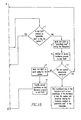
- the attached flowchart illustrates this procedure in detail.
- the architecture of the switch is as follows.
- the master slave bus 16 is used to interconnect units in a hardware system. It consists of an electrical interconnection between the various units and protocols that describe how the signals transported across the electrical interconnection are to be used to facilitate communications between-the units attached to the bus 16.
- Units attached to the bus 16 can be divided into two categories, master units 12 and slave units 14. Master units 12 are capable of initiating communications with other bus 16 units, while slave units 14 simply respond to communications initiated by the master units 12.
- a typical read transaction over the bus 16 starts with a master unit 12 making a request for information from a slave unit 14. The slave unit 14 accepts the requests, does whatever processing it needs to do locally to generate the information, and then returns the requested information and then the slave unit 14 signals that it has completed the transaction.
- a typical write request starts with the master unit 12 sending a write request to a slave unit 14 along with the data to be written. The slave unit 14 acknowledges the transaction, does whatever local processing is needed to process the write request, and then acknowledges the completion of the transaction.
- the control processor subsystem manages the normal operation of the system and also contains a software algorithm that recovers the system automatically in the event of slave unit 14 failure.
- the control processor subsystem also contains memory 18 to hold the program and variables used by the program to help manage and recover the system. It also contains persistent storage 20 so that information may be retained across system restart events or system power down events.
- the control processor system has a watchdog mechanism. The purpose of the watchdog is to detect and recover from certain kinds of failures in the system.
- a watchdog device operates by monitoring another device for activity. If the monitored device is inactive for too long a period, then it performs some action to recover the system.
- the watchdog monitors the control processor's instruction fetch state. If the control processor stops accessing instructions for a long enough time period, the ASX-4000 watchdog resets the control processor subsystem, which instigates a system restart event.
- the first decision is made at the decision point box labeled "3" in the flowchart.
- the key point here is that once malfunctioning slave devices are removed from the system and are replaced with operational hardware, the persistent state that tracks the operational state of the hardware must be reset. If this were not done, the replaced hardware would continue to be treated as malfunctioning by the invention. If the slot 26 is empty, say because malfunctioning hardware was removed, control passes to the box labeled "10". Here, the slot 26, or in general the slave device, is marked as "absent" by placing an indication in the file system associated with the control processor.
- the algorithm proceeds to test the hardware. The algorithm checks to see if the hardware is marked as "potentially bad” at decision point 7 of the flowchart. If the slave device failed, and failure of a slave device causes the control processor to fail, during a previous invocation of the algorithm, the slave device would have been marked as "potentially bad” in the file system. Any slave devices marked as “potentially bad” in the file system must have caused the system to fail, so these devices are marked as "to be skipped” in box "6" of the flowchart.
- the algorithm attempts to test the hardware by accessing the slave device. First, it marks the device as “potentially bad” in the file system.
- the method of marking is critical to the functioning of the algorithm.
- the file system must complete the write operation and have the information stored persistently. BEFORE the device is accessed in box "9".
- the way to accomplish this is to invoke some sort of synchronize operation on the file system. For systems based upon Linux or other POSIX compliant operating systems, the fsync() system call accomplishes this.
- Marconi's implementation of this algorithm in Marconi's ForeThough software uses VxWorks ioctl operation to force synchronization of the entire file system. If the write does not complete before the slave device is accessed, the algorithm cannot recover from non-operational slave devices as the algorithm cannot track the failing slave device across invocations without the completion of this write operation.
- the slave device If, on the other hand, the slave device is not operational, then the system will hang when the control processor attempts to manipulate the slave device. Eventually, hardware watch dog timers will detect that the system has failed and will restart the system. In this case the algorithm restarts and when control transfers to decision point "7", the failed hardware will be detected because of the information left in the file system during the previous invocation of this algorithm. This is how failing hardware is detected and marked as non-operational.
- any master/slave bus 16 devices attached to the bus 16 can be considered as either bus 16 masters or bus 16 slave devices.
- Master devices have the capability to initiate a transaction across the bus 16, while slave units 14 do not initiate any activity except when requested to do so by a master.
- the system control processor is the bus 16 master and all of the portcards act as slave devices.
- a transaction on a master/slave bus 16 starts by a master unit 12 making a request of one of the slave units 14.
- the slave unit 14 either accepts or rejects the request, performs whatever actions it needs to do to satisfy the request, and then returns the result of the request to the master unit 12.
- the master unit 12, the software program 22, and the system control processor 29, just wait During this waiting period, the master unit 12, and the entire system 10, is essentially "frozen". Normally, this period is very small, on the order of a millionth of a second.
Landscapes
- Engineering & Computer Science (AREA)
- Theoretical Computer Science (AREA)
- Quality & Reliability (AREA)
- Physics & Mathematics (AREA)
- General Engineering & Computer Science (AREA)
- General Physics & Mathematics (AREA)
- Hardware Redundancy (AREA)
- Detection And Prevention Of Errors In Transmission (AREA)
- Information Transfer Between Computers (AREA)
- Debugging And Monitoring (AREA)
- Radar Systems Or Details Thereof (AREA)
- Small-Scale Networks (AREA)
- Exchange Systems With Centralized Control (AREA)
- Retry When Errors Occur (AREA)
Claims (13)
- Verfahren zum Übertragen von Daten, umfassend die Schritte:den Versuch, auf eine Slaveeinheit (14) zuzugreifen, die zu einer Anzahl Slaveeinheiten eines Switchs (10) gehört, und zwar durch eine Mastereinheit (12) des Switchs mit einem Signal über einen Bus (16), über den die Mastereinheit (12) und die Slaveeinheit (14) kommunizieren; unddas Feststellen ob die Slaveeinheit (14) eine ausgefallene Slaveeinheit ist;
dadurch gekennzeichnet, dassder Switch (10) veranlasst wird, den Betrieb in einem irregulären Modus zu beenden, falls die Slaveeinheit (14) eine ausgefallene Slaveeinheit ist; undals Reaktion darauf, dass der Switch (10) veranlasst wird, den Betrieb in einem irregulären Modus zu beenden, das automatische Lösen des Switchs von der ausgefallenen Slaveeinheit mit einem Softwareprogramm (22) in dem Switch, das die Mastereinheit (12) anweist, zukünftig nicht mehr auf die ausgefallene Slaveeinheit der Anzahl Slaveeinheiten zuzugreifen, indem es Statusinformation bezüglich der ausgefallenen Slaveeinheit in einem dauerhaften Speicher (28) ablegt, der ein Betriebsende des Switchs in dem irregulären Modus übersteht, und das anschließend verhindert, dass die Mastereinheit (12) versucht, auf die ausgefallene Slaveeinheit zuzugreifen. - Verfahren nach Anspruch 1, worin der Löseschritt den Schritt des Gewinnens von Statusinformation über die Slaveeinheiten aus dem dauerhaften Speicher (28) enthält.
- Verfahren nach Anspruch 2, das einen Schritt enthält, in dem die Information in dem dauerhaften Speicher (28), die der Slaveeinheit (14) zugeordnet ist, von der Kennzeichnung als fehlerhaft in die Kennzeichnung als funktionstüchtig verändert wird, falls der Switch den Betrieb nicht in einem irregulären Modus beendet, nachdem die Mastereinheit (12) versucht, mit der Slaveeinheit (14) Kontakt aufzunehmen.
- Verfahren nach Anspruch 3, das einen Schritt enthält, in dem ein variabler Steckplatz, der aus einer Anzahl Steckplätze (26) des Switchs ausgewählt wird, nicht als möglicherweise ausgefallen gekennzeichnet wird.
- Verfahren nach Anspruch 4, das einen Schritt enthält, in dem festgestellt wird, ob die Slaveeinheit (14) in einem ersten Steckplatz der Anzahl Steckplätze (26) körperlich vorhanden ist.
- Verfahren nach Anspruch 5, das einen Schritt enthält, in dem festgestellt wird, ob der erste Steckplatz dafür markiert ist, übersprungen zu werden.
- Verfahren nach Anspruch 6, das einen Schritt enthält, in dem der variable Steckplatz als möglicherweise fehlerhaft markiert wird, falls er nicht als möglicherweise fehlerhaft markiert ist.
- Verfahren nach Anspruch 7, das einen Schritt enthält, in dem gemeldet wird, dass der variable Steckplatz ausgefallene Hardware enthält und die Mastereinheit (12) daran gehindert wird, einen Zugriff auf den variablen Steckplatz zu versuchen, falls der variable Steckplatz dafür markiert ist, übersprungen zu werden.
- Verfahren nach Anspruch 8, das einen Schritt enthält, in dem versucht wird, auf eine in dem variablen Steckplatz vorhandene Hardware zuzugreifen, falls der variable Steckplatz als möglicherweise fehlerhaft markiert ist.
- Verfahren nach Anspruch 9, das einen Schritt enthält, in dem der variable Steckplatz als fehlerfrei markiert wird, falls der Switch den Betrieb nicht in einem irregulären Modus beendet hat, als die Mastereinheit (12) auf die Slaveeinheit zugegriffen hat.
- Verfahren nach Anspruch 10, das einen Schritt enthält, in dem der normale Betriebsablauf auf der in dem variablen Steckplatz vorhandenen Hardware freigegeben wird, falls der variable Steckplatz als fehlerfrei markiert ist.
- Verfahren nach Anspruch 11, das einen Schritt enthält, in dem der variable Steckplatz auf einen folgenden Steckplatz der Anzahl Steckplätze gesetzt wird.
- Computerlesbares Medium, auf dem computerlesbare Befehle gespeichert sind, die das Verfahren nach irgendeinem der Ansprüche 1 bis 12 ausführen, wenn die Befehle auf einem Computer abgearbeitet werden.
Applications Claiming Priority (2)
| Application Number | Priority Date | Filing Date | Title |
|---|---|---|---|
| US10/782,217 US20050193246A1 (en) | 2004-02-19 | 2004-02-19 | Method, apparatus and software for preventing switch failures in the presence of faults |
| EP05250904A EP1566733B1 (de) | 2004-02-19 | 2005-02-17 | Vorrichtung zur Vermeidung von Schaltungsfehlern in Anwesenheit von Fehlern |
Related Parent Applications (1)
| Application Number | Title | Priority Date | Filing Date |
|---|---|---|---|
| EP05250904A Division EP1566733B1 (de) | 2004-02-19 | 2005-02-17 | Vorrichtung zur Vermeidung von Schaltungsfehlern in Anwesenheit von Fehlern |
Publications (3)
| Publication Number | Publication Date |
|---|---|
| EP1845447A2 EP1845447A2 (de) | 2007-10-17 |
| EP1845447A3 EP1845447A3 (de) | 2008-01-09 |
| EP1845447B1 true EP1845447B1 (de) | 2009-09-02 |
Family
ID=34711860
Family Applications (2)
| Application Number | Title | Priority Date | Filing Date |
|---|---|---|---|
| EP07014916A Expired - Lifetime EP1845447B1 (de) | 2004-02-19 | 2005-02-17 | Verfahren, Vorrichtung und Software zur Vermeidung von Schaltungsfehlern in Anwesenheit von Fehlern |
| EP05250904A Expired - Lifetime EP1566733B1 (de) | 2004-02-19 | 2005-02-17 | Vorrichtung zur Vermeidung von Schaltungsfehlern in Anwesenheit von Fehlern |
Family Applications After (1)
| Application Number | Title | Priority Date | Filing Date |
|---|---|---|---|
| EP05250904A Expired - Lifetime EP1566733B1 (de) | 2004-02-19 | 2005-02-17 | Vorrichtung zur Vermeidung von Schaltungsfehlern in Anwesenheit von Fehlern |
Country Status (5)
| Country | Link |
|---|---|
| US (1) | US20050193246A1 (de) |
| EP (2) | EP1845447B1 (de) |
| JP (1) | JP2005235214A (de) |
| AT (2) | ATE441890T1 (de) |
| DE (2) | DE602005016462D1 (de) |
Families Citing this family (2)
| Publication number | Priority date | Publication date | Assignee | Title |
|---|---|---|---|---|
| WO2017046926A1 (ja) * | 2015-09-17 | 2017-03-23 | 富士通フロンテック株式会社 | 紙葉類取扱装置及び紙葉類取扱装置の制御方法 |
| CN120353741B (zh) * | 2025-06-24 | 2025-09-05 | 苏州元脑智能科技有限公司 | 集成电路总线系统、数据处理方法和可编程逻辑单元 |
Family Cites Families (41)
| Publication number | Priority date | Publication date | Assignee | Title |
|---|---|---|---|---|
| US4597082A (en) * | 1984-03-06 | 1986-06-24 | Controlonics Corporation | Transceiver for multi-drop local area networks |
| US4637022A (en) * | 1984-12-21 | 1987-01-13 | Motorola, Inc. | Internally register-modelled, serially-bussed radio system |
| US4847837A (en) * | 1986-11-07 | 1989-07-11 | The United States Of America As Represented By The Administrator Of The National Aeronautics And Space Administration | Local area network with fault-checking, priorities and redundant backup |
| JPH02130658A (ja) * | 1988-11-11 | 1990-05-18 | Nec Corp | 障害処理方式 |
| JP2761924B2 (ja) * | 1989-06-08 | 1998-06-04 | キヤノン株式会社 | ユニット間通信装置 |
| US5333285A (en) * | 1991-11-21 | 1994-07-26 | International Business Machines Corporation | System crash detect and automatic reset mechanism for processor cards |
| JPH0667909A (ja) * | 1992-08-18 | 1994-03-11 | Mitsubishi Electric Corp | 障害回復方式 |
| US5588112A (en) * | 1992-12-30 | 1996-12-24 | Digital Equipment Corporation | DMA controller for memory scrubbing |
| US5453737A (en) * | 1993-10-08 | 1995-09-26 | Adc Telecommunications, Inc. | Control and communications apparatus |
| US5574945A (en) * | 1993-11-04 | 1996-11-12 | International Business Machines Corporation | Multi channel inter-processor coupling facility processing received commands stored in memory absent status error of channels |
| JP3447404B2 (ja) * | 1994-12-08 | 2003-09-16 | 日本電気株式会社 | マルチプロセッサシステム |
| US5828823A (en) * | 1995-03-01 | 1998-10-27 | Unisys Corporation | Method and apparatus for storing computer data after a power failure |
| US5822512A (en) * | 1995-05-19 | 1998-10-13 | Compaq Computer Corporartion | Switching control in a fault tolerant system |
| JPH09160840A (ja) * | 1995-12-08 | 1997-06-20 | Fuji Facom Corp | バス通信装置 |
| US5793983A (en) * | 1996-01-22 | 1998-08-11 | International Business Machines Corp. | Input/output channel interface which automatically deallocates failed subchannel and re-segments data block for transmitting over a reassigned subchannel |
| US6032271A (en) * | 1996-06-05 | 2000-02-29 | Compaq Computer Corporation | Method and apparatus for identifying faulty devices in a computer system |
| US5802269A (en) * | 1996-06-28 | 1998-09-01 | Intel Corporation | Method and apparatus for power management of distributed direct memory access (DDMA) devices |
| US6000043A (en) * | 1996-06-28 | 1999-12-07 | Intel Corporation | Method and apparatus for management of peripheral devices coupled to a bus |
| US6000040A (en) * | 1996-10-29 | 1999-12-07 | Compaq Computer Corporation | Method and apparatus for diagnosing fault states in a computer system |
| US5864653A (en) * | 1996-12-31 | 1999-01-26 | Compaq Computer Corporation | PCI hot spare capability for failed components |
| US6202067B1 (en) * | 1998-04-07 | 2001-03-13 | Lucent Technologies, Inc. | Method and apparatus for correct and complete transactions in a fault tolerant distributed database system |
| US6463550B1 (en) * | 1998-06-04 | 2002-10-08 | Compaq Information Technologies Group, L.P. | Computer system implementing fault detection and isolation using unique identification codes stored in non-volatile memory |
| US5991900A (en) * | 1998-06-15 | 1999-11-23 | Sun Microsystems, Inc. | Bus controller |
| US6587961B1 (en) * | 1998-06-15 | 2003-07-01 | Sun Microsystems, Inc. | Multi-processor system bridge with controlled access |
| WO2000051000A1 (en) * | 1999-02-24 | 2000-08-31 | Hitachi, Ltd. | Computer system and method of handling trouble of computer system |
| US6718488B1 (en) * | 1999-09-03 | 2004-04-06 | Dell Usa, L.P. | Method and system for responding to a failed bus operation in an information processing system |
| US6496890B1 (en) * | 1999-12-03 | 2002-12-17 | Michael Joseph Azevedo | Bus hang prevention and recovery for data communication systems employing a shared bus interface with multiple bus masters |
| WO2001071501A1 (en) * | 2000-03-22 | 2001-09-27 | Interwoven Inc. | Method and apparatus for storing changes to file attributes without having to store an additional copy of the file contents |
| US6601187B1 (en) * | 2000-03-31 | 2003-07-29 | Hewlett-Packard Development Company, L. P. | System for data replication using redundant pairs of storage controllers, fibre channel fabrics and links therebetween |
| US6735720B1 (en) * | 2000-05-31 | 2004-05-11 | Microsoft Corporation | Method and system for recovering a failed device on a master-slave bus |
| US6574748B1 (en) * | 2000-06-16 | 2003-06-03 | Bull Hn Information Systems Inc. | Fast relief swapping of processors in a data processing system |
| US6928584B2 (en) * | 2000-11-22 | 2005-08-09 | Tellabs Reston, Inc. | Segmented protection system and method |
| US6769078B2 (en) * | 2001-02-08 | 2004-07-27 | International Business Machines Corporation | Method for isolating an I2C bus fault using self bus switching device |
| JP2002300176A (ja) * | 2001-04-02 | 2002-10-11 | Sony Corp | データ通信装置、データ通信方法、データ通信方法のプログラム及びデータ通信方法のプログラムを記録した記録媒体 |
| US6859866B2 (en) * | 2001-10-01 | 2005-02-22 | International Business Machines Corporation | Synchronizing processing of commands invoked against duplexed coupling facility structures |
| US6910153B2 (en) * | 2002-01-03 | 2005-06-21 | International Business Machines Corporation | Method and system for recovery from a coupling facility failure without preallocating space |
| US7043666B2 (en) * | 2002-01-22 | 2006-05-09 | Dell Products L.P. | System and method for recovering from memory errors |
| US7007042B2 (en) * | 2002-03-28 | 2006-02-28 | Hewlett-Packard Development Company, L.P. | System and method for automatic site failover in a storage area network |
| JP3626741B2 (ja) * | 2002-04-16 | 2005-03-09 | オリオン電機株式会社 | データ転送システム |
| TWM242781U (en) * | 2002-11-25 | 2004-09-01 | Quanta Comp Inc | Blade server management system with auxiliary management structure |
| JP2008250632A (ja) * | 2007-03-30 | 2008-10-16 | Matsushita Electric Ind Co Ltd | データ処理システム |
-
2004
- 2004-02-19 US US10/782,217 patent/US20050193246A1/en not_active Abandoned
-
2005
- 2005-02-17 DE DE602005016462T patent/DE602005016462D1/de not_active Expired - Lifetime
- 2005-02-17 EP EP07014916A patent/EP1845447B1/de not_active Expired - Lifetime
- 2005-02-17 JP JP2005039974A patent/JP2005235214A/ja active Pending
- 2005-02-17 EP EP05250904A patent/EP1566733B1/de not_active Expired - Lifetime
- 2005-02-17 AT AT07014916T patent/ATE441890T1/de not_active IP Right Cessation
- 2005-02-17 AT AT05250904T patent/ATE373842T1/de not_active IP Right Cessation
- 2005-02-17 DE DE602005002485T patent/DE602005002485T2/de not_active Expired - Lifetime
Also Published As
| Publication number | Publication date |
|---|---|
| EP1566733B1 (de) | 2007-09-19 |
| EP1566733A1 (de) | 2005-08-24 |
| EP1845447A3 (de) | 2008-01-09 |
| DE602005002485D1 (de) | 2007-10-31 |
| ATE441890T1 (de) | 2009-09-15 |
| DE602005002485T2 (de) | 2008-06-26 |
| EP1845447A2 (de) | 2007-10-17 |
| ATE373842T1 (de) | 2007-10-15 |
| US20050193246A1 (en) | 2005-09-01 |
| DE602005016462D1 (de) | 2009-10-15 |
| JP2005235214A (ja) | 2005-09-02 |
Similar Documents
| Publication | Publication Date | Title |
|---|---|---|
| US6493796B1 (en) | Method and apparatus for maintaining consistency of data stored in a group of mirroring devices | |
| US5870301A (en) | System control apparatus including a master control unit and a slave control unit which maintain coherent information | |
| US5423044A (en) | Shared, distributed lock manager for loosely coupled processing systems | |
| US6321346B1 (en) | External storage | |
| US5944838A (en) | Method for fast queue restart after redundant I/O path failover | |
| US4894828A (en) | Multiple sup swap mechanism | |
| JP3481737B2 (ja) | ダンプ採取装置およびダンプ採取方法 | |
| EP1119809A1 (de) | Prozessüberwachung in einem rechnersystem | |
| JP2000181887A (ja) | 情報処理装置における障害処理方法及び記憶制御装置 | |
| US6480953B1 (en) | Method and apparatus for ensuring system configuration data structure coherency across multiple controllers in a data storage system | |
| EP0397471B1 (de) | Initialisierungs-system und -methoden für Eingang/Ausgang-Verarbeitungseinheiten | |
| US5742851A (en) | Information processing system having function to detect fault in external bus | |
| US8032791B2 (en) | Diagnosis of and response to failure at reset in a data processing system | |
| JPH10154085A (ja) | 二重化された監視/制御プロセッサによるシステム監視・制御方法および二重化監視/制御プロセッサ・システム | |
| EP1566733B1 (de) | Vorrichtung zur Vermeidung von Schaltungsfehlern in Anwesenheit von Fehlern | |
| JP2002543521A (ja) | 自動的にモジュールをコンピュータシステムに再び組み込む方法および装置 | |
| JP2000293391A (ja) | 大規模メモリシステム管理方法および装置 | |
| EP1703392A2 (de) | Verfahren und Vorrichtung zur Feststellung von Fehlern in einem geteilten Grosscomputersystem | |
| KR19990050460A (ko) | 고 가용성 시스템의 장애 복구방법 및 장치 | |
| CN100437499C (zh) | 计算机平台快取资料备援处理方法及系统 | |
| JP3312652B2 (ja) | マルチプロセッサアーキテクチャでのデータベース管理方式 | |
| JP2001175545A (ja) | サーバシステムおよび障害診断方法ならびに記録媒体 | |
| JP2815730B2 (ja) | アダプタ及びコンピュータシステム | |
| JP3340284B2 (ja) | 冗長システム | |
| JPH02153437A (ja) | 出力メッセージ回復方式 |
Legal Events
| Date | Code | Title | Description |
|---|---|---|---|
| PUAI | Public reference made under article 153(3) epc to a published international application that has entered the european phase |
Free format text: ORIGINAL CODE: 0009012 |
|
| AC | Divisional application: reference to earlier application |
Ref document number: 1566733 Country of ref document: EP Kind code of ref document: P |
|
| AK | Designated contracting states |
Kind code of ref document: A2 Designated state(s): AT BE BG CH CY CZ DE DK EE ES FI FR GB GR HU IE IS IT LI LT LU MC NL PL PT RO SE SI SK TR |
|
| PUAL | Search report despatched |
Free format text: ORIGINAL CODE: 0009013 |
|
| AK | Designated contracting states |
Kind code of ref document: A3 Designated state(s): AT BE BG CH CY CZ DE DK EE ES FI FR GB GR HU IE IS IT LI LT LU MC NL PL PT RO SE SI SK TR |
|
| 17P | Request for examination filed |
Effective date: 20080707 |
|
| 17Q | First examination report despatched |
Effective date: 20080808 |
|
| AKX | Designation fees paid |
Designated state(s): AT BE BG CH CY CZ DE DK EE ES FI FR GB GR HU IE IS IT LI LT LU MC NL PL PT RO SE SI SK TR |
|
| GRAP | Despatch of communication of intention to grant a patent |
Free format text: ORIGINAL CODE: EPIDOSNIGR1 |
|
| GRAS | Grant fee paid |
Free format text: ORIGINAL CODE: EPIDOSNIGR3 |
|
| GRAA | (expected) grant |
Free format text: ORIGINAL CODE: 0009210 |
|
| AC | Divisional application: reference to earlier application |
Ref document number: 1566733 Country of ref document: EP Kind code of ref document: P |
|
| AK | Designated contracting states |
Kind code of ref document: B1 Designated state(s): AT BE BG CH CY CZ DE DK EE ES FI FR GB GR HU IE IS IT LI LT LU MC NL PL PT RO SE SI SK TR |
|
| REG | Reference to a national code |
Ref country code: CH Ref legal event code: EP |
|
| REG | Reference to a national code |
Ref country code: IE Ref legal event code: FG4D |
|
| REF | Corresponds to: |
Ref document number: 602005016462 Country of ref document: DE Date of ref document: 20091015 Kind code of ref document: P |
|
| PG25 | Lapsed in a contracting state [announced via postgrant information from national office to epo] |
Ref country code: LT Free format text: LAPSE BECAUSE OF FAILURE TO SUBMIT A TRANSLATION OF THE DESCRIPTION OR TO PAY THE FEE WITHIN THE PRESCRIBED TIME-LIMIT Effective date: 20090902 Ref country code: SE Free format text: LAPSE BECAUSE OF FAILURE TO SUBMIT A TRANSLATION OF THE DESCRIPTION OR TO PAY THE FEE WITHIN THE PRESCRIBED TIME-LIMIT Effective date: 20090902 Ref country code: FI Free format text: LAPSE BECAUSE OF FAILURE TO SUBMIT A TRANSLATION OF THE DESCRIPTION OR TO PAY THE FEE WITHIN THE PRESCRIBED TIME-LIMIT Effective date: 20090902 |
|
| NLV1 | Nl: lapsed or annulled due to failure to fulfill the requirements of art. 29p and 29m of the patents act | ||
| LTIE | Lt: invalidation of european patent or patent extension |
Effective date: 20090902 |
|
| PG25 | Lapsed in a contracting state [announced via postgrant information from national office to epo] |
Ref country code: NL Free format text: LAPSE BECAUSE OF FAILURE TO SUBMIT A TRANSLATION OF THE DESCRIPTION OR TO PAY THE FEE WITHIN THE PRESCRIBED TIME-LIMIT Effective date: 20090902 Ref country code: PL Free format text: LAPSE BECAUSE OF FAILURE TO SUBMIT A TRANSLATION OF THE DESCRIPTION OR TO PAY THE FEE WITHIN THE PRESCRIBED TIME-LIMIT Effective date: 20090902 Ref country code: SI Free format text: LAPSE BECAUSE OF FAILURE TO SUBMIT A TRANSLATION OF THE DESCRIPTION OR TO PAY THE FEE WITHIN THE PRESCRIBED TIME-LIMIT Effective date: 20090902 |
|
| PG25 | Lapsed in a contracting state [announced via postgrant information from national office to epo] |
Ref country code: CY Free format text: LAPSE BECAUSE OF FAILURE TO SUBMIT A TRANSLATION OF THE DESCRIPTION OR TO PAY THE FEE WITHIN THE PRESCRIBED TIME-LIMIT Effective date: 20090902 |
|
| PG25 | Lapsed in a contracting state [announced via postgrant information from national office to epo] |
Ref country code: ES Free format text: LAPSE BECAUSE OF FAILURE TO SUBMIT A TRANSLATION OF THE DESCRIPTION OR TO PAY THE FEE WITHIN THE PRESCRIBED TIME-LIMIT Effective date: 20091213 Ref country code: IS Free format text: LAPSE BECAUSE OF FAILURE TO SUBMIT A TRANSLATION OF THE DESCRIPTION OR TO PAY THE FEE WITHIN THE PRESCRIBED TIME-LIMIT Effective date: 20100102 Ref country code: PT Free format text: LAPSE BECAUSE OF FAILURE TO SUBMIT A TRANSLATION OF THE DESCRIPTION OR TO PAY THE FEE WITHIN THE PRESCRIBED TIME-LIMIT Effective date: 20100104 Ref country code: EE Free format text: LAPSE BECAUSE OF FAILURE TO SUBMIT A TRANSLATION OF THE DESCRIPTION OR TO PAY THE FEE WITHIN THE PRESCRIBED TIME-LIMIT Effective date: 20090902 Ref country code: CZ Free format text: LAPSE BECAUSE OF FAILURE TO SUBMIT A TRANSLATION OF THE DESCRIPTION OR TO PAY THE FEE WITHIN THE PRESCRIBED TIME-LIMIT Effective date: 20090902 Ref country code: RO Free format text: LAPSE BECAUSE OF FAILURE TO SUBMIT A TRANSLATION OF THE DESCRIPTION OR TO PAY THE FEE WITHIN THE PRESCRIBED TIME-LIMIT Effective date: 20090902 |
|
| RAP2 | Party data changed (patent owner data changed or rights of a patent transferred) |
Owner name: ERICSSON AB |
|
| PG25 | Lapsed in a contracting state [announced via postgrant information from national office to epo] |
Ref country code: SK Free format text: LAPSE BECAUSE OF FAILURE TO SUBMIT A TRANSLATION OF THE DESCRIPTION OR TO PAY THE FEE WITHIN THE PRESCRIBED TIME-LIMIT Effective date: 20090902 |
|
| PGFP | Annual fee paid to national office [announced via postgrant information from national office to epo] |
Ref country code: IT Payment date: 20100223 Year of fee payment: 6 |
|
| PG25 | Lapsed in a contracting state [announced via postgrant information from national office to epo] |
Ref country code: BE Free format text: LAPSE BECAUSE OF FAILURE TO SUBMIT A TRANSLATION OF THE DESCRIPTION OR TO PAY THE FEE WITHIN THE PRESCRIBED TIME-LIMIT Effective date: 20090902 Ref country code: AT Free format text: LAPSE BECAUSE OF FAILURE TO SUBMIT A TRANSLATION OF THE DESCRIPTION OR TO PAY THE FEE WITHIN THE PRESCRIBED TIME-LIMIT Effective date: 20090902 |
|
| PGFP | Annual fee paid to national office [announced via postgrant information from national office to epo] |
Ref country code: DE Payment date: 20100226 Year of fee payment: 6 Ref country code: GB Payment date: 20100224 Year of fee payment: 6 |
|
| PLBE | No opposition filed within time limit |
Free format text: ORIGINAL CODE: 0009261 |
|
| STAA | Information on the status of an ep patent application or granted ep patent |
Free format text: STATUS: NO OPPOSITION FILED WITHIN TIME LIMIT |
|
| PG25 | Lapsed in a contracting state [announced via postgrant information from national office to epo] |
Ref country code: DK Free format text: LAPSE BECAUSE OF FAILURE TO SUBMIT A TRANSLATION OF THE DESCRIPTION OR TO PAY THE FEE WITHIN THE PRESCRIBED TIME-LIMIT Effective date: 20090902 |
|
| 26N | No opposition filed |
Effective date: 20100603 |
|
| REG | Reference to a national code |
Ref country code: CH Ref legal event code: PL |
|
| PG25 | Lapsed in a contracting state [announced via postgrant information from national office to epo] |
Ref country code: GR Free format text: LAPSE BECAUSE OF FAILURE TO SUBMIT A TRANSLATION OF THE DESCRIPTION OR TO PAY THE FEE WITHIN THE PRESCRIBED TIME-LIMIT Effective date: 20091203 Ref country code: MC Free format text: LAPSE BECAUSE OF NON-PAYMENT OF DUE FEES Effective date: 20100301 Ref country code: CH Free format text: LAPSE BECAUSE OF NON-PAYMENT OF DUE FEES Effective date: 20100228 Ref country code: LI Free format text: LAPSE BECAUSE OF NON-PAYMENT OF DUE FEES Effective date: 20100228 |
|
| REG | Reference to a national code |
Ref country code: FR Ref legal event code: ST Effective date: 20101029 |
|
| PG25 | Lapsed in a contracting state [announced via postgrant information from national office to epo] |
Ref country code: FR Free format text: LAPSE BECAUSE OF NON-PAYMENT OF DUE FEES Effective date: 20100301 Ref country code: IE Free format text: LAPSE BECAUSE OF NON-PAYMENT OF DUE FEES Effective date: 20100217 |
|
| GBPC | Gb: european patent ceased through non-payment of renewal fee |
Effective date: 20110217 |
|
| PG25 | Lapsed in a contracting state [announced via postgrant information from national office to epo] |
Ref country code: IT Free format text: LAPSE BECAUSE OF NON-PAYMENT OF DUE FEES Effective date: 20110217 |
|
| REG | Reference to a national code |
Ref country code: DE Ref legal event code: R119 Ref document number: 602005016462 Country of ref document: DE Effective date: 20110901 |
|
| PG25 | Lapsed in a contracting state [announced via postgrant information from national office to epo] |
Ref country code: GB Free format text: LAPSE BECAUSE OF NON-PAYMENT OF DUE FEES Effective date: 20110217 |
|
| PG25 | Lapsed in a contracting state [announced via postgrant information from national office to epo] |
Ref country code: HU Free format text: LAPSE BECAUSE OF FAILURE TO SUBMIT A TRANSLATION OF THE DESCRIPTION OR TO PAY THE FEE WITHIN THE PRESCRIBED TIME-LIMIT Effective date: 20100303 Ref country code: LU Free format text: LAPSE BECAUSE OF NON-PAYMENT OF DUE FEES Effective date: 20100217 Ref country code: BG Free format text: LAPSE BECAUSE OF FAILURE TO SUBMIT A TRANSLATION OF THE DESCRIPTION OR TO PAY THE FEE WITHIN THE PRESCRIBED TIME-LIMIT Effective date: 20090902 |
|
| PG25 | Lapsed in a contracting state [announced via postgrant information from national office to epo] |
Ref country code: TR Free format text: LAPSE BECAUSE OF FAILURE TO SUBMIT A TRANSLATION OF THE DESCRIPTION OR TO PAY THE FEE WITHIN THE PRESCRIBED TIME-LIMIT Effective date: 20090902 |
|
| PG25 | Lapsed in a contracting state [announced via postgrant information from national office to epo] |
Ref country code: DE Free format text: LAPSE BECAUSE OF NON-PAYMENT OF DUE FEES Effective date: 20110901 |