EP1845364A2 - Detecting apparatus and method - Google Patents
Detecting apparatus and method Download PDFInfo
- Publication number
- EP1845364A2 EP1845364A2 EP20070105871 EP07105871A EP1845364A2 EP 1845364 A2 EP1845364 A2 EP 1845364A2 EP 20070105871 EP20070105871 EP 20070105871 EP 07105871 A EP07105871 A EP 07105871A EP 1845364 A2 EP1845364 A2 EP 1845364A2
- Authority
- EP
- European Patent Office
- Prior art keywords
- infiltrative
- transmission path
- holding member
- porous material
- detecting
- Prior art date
- Legal status (The legal status is an assumption and is not a legal conclusion. Google has not performed a legal analysis and makes no representation as to the accuracy of the status listed.)
- Withdrawn
Links
- 238000000034 method Methods 0.000 title claims description 29
- 230000005540 biological transmission Effects 0.000 claims abstract description 137
- 239000007788 liquid Substances 0.000 claims abstract description 113
- 230000005684 electric field Effects 0.000 claims abstract description 31
- 230000001902 propagating effect Effects 0.000 claims abstract description 26
- 238000009826 distribution Methods 0.000 claims abstract description 25
- 238000001764 infiltration Methods 0.000 claims abstract description 20
- 230000008595 infiltration Effects 0.000 claims abstract description 20
- 239000011148 porous material Substances 0.000 claims description 133
- 239000002184 metal Substances 0.000 claims description 20
- 229910052751 metal Inorganic materials 0.000 claims description 20
- 230000005484 gravity Effects 0.000 claims description 6
- 238000007710 freezing Methods 0.000 claims description 4
- 230000008014 freezing Effects 0.000 claims description 4
- 239000003550 marker Substances 0.000 claims description 4
- 239000002657 fibrous material Substances 0.000 claims description 3
- 238000001816 cooling Methods 0.000 claims description 2
- 239000000523 sample Substances 0.000 description 134
- 239000004793 Polystyrene Substances 0.000 description 23
- 239000000463 material Substances 0.000 description 23
- 229920002223 polystyrene Polymers 0.000 description 23
- 230000003993 interaction Effects 0.000 description 21
- 238000001514 detection method Methods 0.000 description 20
- 108020004414 DNA Proteins 0.000 description 19
- 239000011347 resin Substances 0.000 description 14
- 229920005989 resin Polymers 0.000 description 14
- 238000001228 spectrum Methods 0.000 description 12
- 239000000758 substrate Substances 0.000 description 11
- 230000008859 change Effects 0.000 description 9
- 239000004695 Polyether sulfone Substances 0.000 description 8
- 229920006393 polyether sulfone Polymers 0.000 description 8
- 229910001218 Gallium arsenide Inorganic materials 0.000 description 7
- 239000004677 Nylon Substances 0.000 description 7
- 239000004743 Polypropylene Substances 0.000 description 7
- 239000000853 adhesive Substances 0.000 description 7
- 230000001070 adhesive effect Effects 0.000 description 7
- 239000012528 membrane Substances 0.000 description 7
- 229920001778 nylon Polymers 0.000 description 7
- 229920002492 poly(sulfone) Polymers 0.000 description 7
- -1 polypropylene Polymers 0.000 description 7
- 229920001155 polypropylene Polymers 0.000 description 7
- 230000001105 regulatory effect Effects 0.000 description 7
- 238000005259 measurement Methods 0.000 description 6
- 230000003287 optical effect Effects 0.000 description 6
- 238000004458 analytical method Methods 0.000 description 5
- UMIVXZPTRXBADB-UHFFFAOYSA-N benzocyclobutene Chemical compound C1=CC=C2CCC2=C1 UMIVXZPTRXBADB-UHFFFAOYSA-N 0.000 description 5
- 239000000835 fiber Substances 0.000 description 5
- 238000001914 filtration Methods 0.000 description 5
- 239000010419 fine particle Substances 0.000 description 5
- 102000053602 DNA Human genes 0.000 description 4
- 238000010521 absorption reaction Methods 0.000 description 4
- 230000008878 coupling Effects 0.000 description 4
- 238000010168 coupling process Methods 0.000 description 4
- 238000005859 coupling reaction Methods 0.000 description 4
- 102000004169 proteins and genes Human genes 0.000 description 4
- 108090000623 proteins and genes Proteins 0.000 description 4
- 239000000470 constituent Substances 0.000 description 3
- 238000001704 evaporation Methods 0.000 description 3
- 230000008020 evaporation Effects 0.000 description 3
- 238000002474 experimental method Methods 0.000 description 3
- 239000003365 glass fiber Substances 0.000 description 3
- 239000000047 product Substances 0.000 description 3
- 238000001179 sorption measurement Methods 0.000 description 3
- 239000010936 titanium Substances 0.000 description 3
- 238000007738 vacuum evaporation Methods 0.000 description 3
- IJGRMHOSHXDMSA-UHFFFAOYSA-N Atomic nitrogen Chemical compound N#N IJGRMHOSHXDMSA-UHFFFAOYSA-N 0.000 description 2
- 239000000020 Nitrocellulose Substances 0.000 description 2
- XUIMIQQOPSSXEZ-UHFFFAOYSA-N Silicon Chemical compound [Si] XUIMIQQOPSSXEZ-UHFFFAOYSA-N 0.000 description 2
- 108020004682 Single-Stranded DNA Proteins 0.000 description 2
- PPBRXRYQALVLMV-UHFFFAOYSA-N Styrene Chemical compound C=CC1=CC=CC=C1 PPBRXRYQALVLMV-UHFFFAOYSA-N 0.000 description 2
- RTAQQCXQSZGOHL-UHFFFAOYSA-N Titanium Chemical compound [Ti] RTAQQCXQSZGOHL-UHFFFAOYSA-N 0.000 description 2
- FJWGYAHXMCUOOM-QHOUIDNNSA-N [(2s,3r,4s,5r,6r)-2-[(2r,3r,4s,5r,6s)-4,5-dinitrooxy-2-(nitrooxymethyl)-6-[(2r,3r,4s,5r,6s)-4,5,6-trinitrooxy-2-(nitrooxymethyl)oxan-3-yl]oxyoxan-3-yl]oxy-3,5-dinitrooxy-6-(nitrooxymethyl)oxan-4-yl] nitrate Chemical compound O([C@@H]1O[C@@H]([C@H]([C@H](O[N+]([O-])=O)[C@H]1O[N+]([O-])=O)O[C@H]1[C@@H]([C@@H](O[N+]([O-])=O)[C@H](O[N+]([O-])=O)[C@@H](CO[N+]([O-])=O)O1)O[N+]([O-])=O)CO[N+](=O)[O-])[C@@H]1[C@@H](CO[N+]([O-])=O)O[C@@H](O[N+]([O-])=O)[C@H](O[N+]([O-])=O)[C@H]1O[N+]([O-])=O FJWGYAHXMCUOOM-QHOUIDNNSA-N 0.000 description 2
- 230000009471 action Effects 0.000 description 2
- 229920002678 cellulose Polymers 0.000 description 2
- 239000001913 cellulose Substances 0.000 description 2
- 238000010276 construction Methods 0.000 description 2
- 238000007796 conventional method Methods 0.000 description 2
- 239000003814 drug Substances 0.000 description 2
- 238000001035 drying Methods 0.000 description 2
- 239000011521 glass Substances 0.000 description 2
- PCHJSUWPFVWCPO-UHFFFAOYSA-N gold Chemical compound [Au] PCHJSUWPFVWCPO-UHFFFAOYSA-N 0.000 description 2
- 239000010931 gold Substances 0.000 description 2
- 229910052737 gold Inorganic materials 0.000 description 2
- 230000007246 mechanism Effects 0.000 description 2
- 229920001220 nitrocellulos Polymers 0.000 description 2
- 229940079938 nitrocellulose Drugs 0.000 description 2
- 108020004707 nucleic acids Proteins 0.000 description 2
- 102000039446 nucleic acids Human genes 0.000 description 2
- 150000007523 nucleic acids Chemical class 0.000 description 2
- 230000002093 peripheral effect Effects 0.000 description 2
- 229920002120 photoresistant polymer Polymers 0.000 description 2
- 238000003825 pressing Methods 0.000 description 2
- 239000010453 quartz Substances 0.000 description 2
- 229910052710 silicon Inorganic materials 0.000 description 2
- 239000010703 silicon Substances 0.000 description 2
- VYPSYNLAJGMNEJ-UHFFFAOYSA-N silicon dioxide Inorganic materials O=[Si]=O VYPSYNLAJGMNEJ-UHFFFAOYSA-N 0.000 description 2
- 230000001954 sterilising effect Effects 0.000 description 2
- 238000004659 sterilization and disinfection Methods 0.000 description 2
- 229910052719 titanium Inorganic materials 0.000 description 2
- LFQSCWFLJHTTHZ-UHFFFAOYSA-N Ethanol Chemical compound CCO LFQSCWFLJHTTHZ-UHFFFAOYSA-N 0.000 description 1
- 238000004026 adhesive bonding Methods 0.000 description 1
- 238000013459 approach Methods 0.000 description 1
- 230000002238 attenuated effect Effects 0.000 description 1
- 239000008280 blood Substances 0.000 description 1
- 210000004369 blood Anatomy 0.000 description 1
- 238000007664 blowing Methods 0.000 description 1
- 238000009833 condensation Methods 0.000 description 1
- 230000005494 condensation Effects 0.000 description 1
- 239000002826 coolant Substances 0.000 description 1
- 230000007423 decrease Effects 0.000 description 1
- 230000005670 electromagnetic radiation Effects 0.000 description 1
- 238000004993 emission spectroscopy Methods 0.000 description 1
- 239000012520 frozen sample Substances 0.000 description 1
- 230000002209 hydrophobic effect Effects 0.000 description 1
- 238000005286 illumination Methods 0.000 description 1
- 238000007689 inspection Methods 0.000 description 1
- 239000011810 insulating material Substances 0.000 description 1
- 238000004519 manufacturing process Methods 0.000 description 1
- 238000012986 modification Methods 0.000 description 1
- 230000004048 modification Effects 0.000 description 1
- 238000012544 monitoring process Methods 0.000 description 1
- 229910052757 nitrogen Inorganic materials 0.000 description 1
- 239000003960 organic solvent Substances 0.000 description 1
- 239000002245 particle Substances 0.000 description 1
- 238000000206 photolithography Methods 0.000 description 1
- 238000001020 plasma etching Methods 0.000 description 1
- 239000002244 precipitate Substances 0.000 description 1
- 230000005855 radiation Effects 0.000 description 1
- 230000035945 sensitivity Effects 0.000 description 1
- 239000007787 solid Substances 0.000 description 1
- 239000002904 solvent Substances 0.000 description 1
- 238000004611 spectroscopical analysis Methods 0.000 description 1
- 239000000126 substance Substances 0.000 description 1
- 210000004243 sweat Anatomy 0.000 description 1
- 238000001328 terahertz time-domain spectroscopy Methods 0.000 description 1
- 238000012546 transfer Methods 0.000 description 1
- 230000009466 transformation Effects 0.000 description 1
- 238000002834 transmittance Methods 0.000 description 1
- XLYOFNOQVPJJNP-UHFFFAOYSA-N water Substances O XLYOFNOQVPJJNP-UHFFFAOYSA-N 0.000 description 1
Images





Classifications
-
- G—PHYSICS
- G01—MEASURING; TESTING
- G01N—INVESTIGATING OR ANALYSING MATERIALS BY DETERMINING THEIR CHEMICAL OR PHYSICAL PROPERTIES
- G01N21/00—Investigating or analysing materials by the use of optical means, i.e. using sub-millimetre waves, infrared, visible or ultraviolet light
- G01N21/17—Systems in which incident light is modified in accordance with the properties of the material investigated
- G01N21/25—Colour; Spectral properties, i.e. comparison of effect of material on the light at two or more different wavelengths or wavelength bands
- G01N21/31—Investigating relative effect of material at wavelengths characteristic of specific elements or molecules, e.g. atomic absorption spectrometry
- G01N21/35—Investigating relative effect of material at wavelengths characteristic of specific elements or molecules, e.g. atomic absorption spectrometry using infrared light
- G01N21/3581—Investigating relative effect of material at wavelengths characteristic of specific elements or molecules, e.g. atomic absorption spectrometry using infrared light using far infrared light; using Terahertz radiation
-
- G—PHYSICS
- G01—MEASURING; TESTING
- G01N—INVESTIGATING OR ANALYSING MATERIALS BY DETERMINING THEIR CHEMICAL OR PHYSICAL PROPERTIES
- G01N21/00—Investigating or analysing materials by the use of optical means, i.e. using sub-millimetre waves, infrared, visible or ultraviolet light
- G01N21/01—Arrangements or apparatus for facilitating the optical investigation
- G01N21/03—Cuvette constructions
-
- G—PHYSICS
- G01—MEASURING; TESTING
- G01N—INVESTIGATING OR ANALYSING MATERIALS BY DETERMINING THEIR CHEMICAL OR PHYSICAL PROPERTIES
- G01N21/00—Investigating or analysing materials by the use of optical means, i.e. using sub-millimetre waves, infrared, visible or ultraviolet light
- G01N21/17—Systems in which incident light is modified in accordance with the properties of the material investigated
- G01N21/25—Colour; Spectral properties, i.e. comparison of effect of material on the light at two or more different wavelengths or wavelength bands
- G01N21/31—Investigating relative effect of material at wavelengths characteristic of specific elements or molecules, e.g. atomic absorption spectrometry
- G01N21/35—Investigating relative effect of material at wavelengths characteristic of specific elements or molecules, e.g. atomic absorption spectrometry using infrared light
- G01N21/3577—Investigating relative effect of material at wavelengths characteristic of specific elements or molecules, e.g. atomic absorption spectrometry using infrared light for analysing liquids, e.g. polluted water
-
- G—PHYSICS
- G01—MEASURING; TESTING
- G01N—INVESTIGATING OR ANALYSING MATERIALS BY DETERMINING THEIR CHEMICAL OR PHYSICAL PROPERTIES
- G01N22/00—Investigating or analysing materials by the use of microwaves or radio waves, i.e. electromagnetic waves with a wavelength of one millimetre or more
-
- G—PHYSICS
- G01—MEASURING; TESTING
- G01N—INVESTIGATING OR ANALYSING MATERIALS BY DETERMINING THEIR CHEMICAL OR PHYSICAL PROPERTIES
- G01N21/00—Investigating or analysing materials by the use of optical means, i.e. using sub-millimetre waves, infrared, visible or ultraviolet light
- G01N21/01—Arrangements or apparatus for facilitating the optical investigation
- G01N21/03—Cuvette constructions
- G01N2021/0346—Capillary cells; Microcells
-
- G—PHYSICS
- G01—MEASURING; TESTING
- G01N—INVESTIGATING OR ANALYSING MATERIALS BY DETERMINING THEIR CHEMICAL OR PHYSICAL PROPERTIES
- G01N21/00—Investigating or analysing materials by the use of optical means, i.e. using sub-millimetre waves, infrared, visible or ultraviolet light
- G01N21/01—Arrangements or apparatus for facilitating the optical investigation
- G01N21/03—Cuvette constructions
- G01N2021/0346—Capillary cells; Microcells
- G01N2021/035—Supports for sample drops
Definitions
- the present invention relates to a detecting apparatus and method for detecting information, such as characteristics, identification, concentration, and presence or absence, of a liquid object or sample, by using an electromagnetic wave.
- the present invention relates to a detecting apparatus and method using an electromagnetic wave at a frequency or frequencies including at least a portion of a frequency range from 30 GHz to 30 THz.
- the electromagnetic wave including at least a component in the above frequency range is called a THz wave in this specification.
- APPLIED PHYSICS LETTERS/Vol.80, No.1, 2002, p.154 discloses a proposal in which a THz-wave transmission path is formed on a substrate, DNA water solution is dripped and dried on the transmission path, and analysis of the DNA is carried out by detecting a change in a THz-wave transmission property of the transmission path.
- the proposal uses the fact that a dielectric constant of single-stranded DNA for the THz wave differs from that of double-stranded DNA, and shows that single-stranded DNA and double-stranded DNA can be separately identified based on a difference in the THz-wave transmission property of the transmission path.
- optical characteristics of material such as an absorption coefficient, complex refractive index, and the like
- analysis, detection, identification, etc. of the material can be conducted.
- no means is used for dripping a liquid sample onto the transmission path in an improved controllability, and accordingly it is typically not easy to accurately drip the sample on the transmission path.
- the dripped liquid sample is likely to flow and spread, so a location of the dripped sample on the transmission path and an interaction area between the THz wave and the sample are not easy to appropriately regulate.
- a detecting apparatus for detecting information of a liquid object or sample, which includes a transmission path, a THz wave supplying unit, a THz wave detecting unit, and an infiltrative holding member for infiltration and holding of a liquid sample.
- the supplying unit supplies electromagnetic radiation in a frequency range between 30 GHz and 30 THz, or THz wave, to the transmission path.
- the detecting unit detects the THz wave transmitted through the transmission path.
- the infiltrative holding member is set at a location containing at least a portion in which an electric field distribution of the THz wave propagating along the transmission path extends.
- a detecting method for detecting information of a liquid object or sample which includes a step of preparing an apparatus including a transmission path, a THz wave supplying unit, and a THz wave detecting unit, and a second of setting an infiltrative holding member for infiltration and holding of a liquid sample at a location containing at least a portion in which an electric field distribution of THz wave propagating along the transmission path extends.
- the supplying unit supplies electromagnetic wave in a frequency range between 30 GHz and 30 THz, or THz wave, to the transmission path.
- the detecting unit detects the THz wave transmitted through the transmission path.
- the THz wave is supplied to the transmission path under a condition in which the liquid sample is infiltrated and held in the infiltrative holding member, and the THz wave transmitted through the transmission path is detected to detect information of the liquid sample.
- the infiltrative holding member for infiltration and holding of a liquid object or sample is used, so the location of the dripped liquid object or sample on the transmission path and the interaction area between the THz wave and the liquid obj ect or sample can be accurately and precisely regulated.
- Fig. 1A is a plan view illustrating a first embodiment and example of a detecting apparatus and method according to the present invention, which uses an infiltrative holding member for infiltration and holding of a liquid sample.
- Fig. 1B is a cross-sectional view taken along line B-B' of Fig. 1A.
- Fig. 1C is a cross-sectional view taken along line A-A' of Fig. 1A.
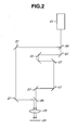
- Fig. 2 is a view illustrating an optical system for supplying laser light to a transmission path of the detecting apparatus of the present invention.
- Fig. 3 is a graph showing exemplified spectra of a THz wave detected by a detecting unit of the detecting apparatus of the present invention.
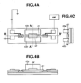
- Fig. 4A is a plan view illustrating a second embodiment of a detecting apparatus and method according to the present invention, in which tow sides of an infiltrative holding member (a porous material) for infiltration and holding of a liquid sample are set by non-infiltrative members (resin plates).
- an infiltrative holding member a porous material
- non-infiltrative members resin plates
- Fig. 4B is a cross-sectional view taken along line B-B' of Fig. 4A.
- Fig. 4C is a cross-sectional view taken along line A-A' of Fig. 4A.
- Fig. 5A is a plan view illustrating a third embodiment of a detecting apparatus and method according to the present invention, in which an infiltrative holding member (a porous material) for infiltration and holding of a liquid sample is set by bonding.
- an infiltrative holding member a porous material
- Fig. 5B is a cross-sectional view taken along line B-B' of Fig. 5A.
- Fig. 5C is a cross-sectional view taken along line A-A' of Fig. 5A.
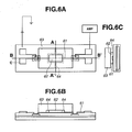
- Fig. 6A is a plan view illustrating a fourth embodiment of a detecting apparatus and method according to the present invention, in which a flow path is provided near an infiltrative holding member (a porous material) for infiltration and holding of a liquid sample.
- an infiltrative holding member a porous material
- Fig. 6B is a cross-sectional view taken along line B-B' of Fig. 6A.
- Fig. 6C is a cross-sectional view taken along line A-A' of Fig. 6A.
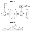
- Fig. 7A is a plan view illustrating a fifth embodiment of a detecting apparatus and method according to the present invention, in which a hole is formed in a second resin layer, and an infiltrative holding member (a porous material) for infiltration and holding of a liquid sample is disposed in the hole.
- an infiltrative holding member a porous material
- Fig. 7B is a cross-sectional view taken along line B-B' of Fig. 7A.
- Fig. 7C is a cross-sectional view taken along line A-A' of Fig. 7A.
- Fig. 8A is a plan view illustrating a sixth embodiment of a detecting apparatus and method according to the present invention, in which a dielectric layer includes an infiltrative holding member (a porous material) for infiltration and holding of a liquid sample.
- a dielectric layer includes an infiltrative holding member (a porous material) for infiltration and holding of a liquid sample.
- Fig. 8B is a cross-sectional view taken along line B-B' of Fig. 8A.
- Fig. 8C is a cross-sectional view taken along line A-A' of Fig. 8A.
- Fig. 9A is a plan view illustrating a location of an infiltrative holding member (a porous material) relative to a transmission path.
- Fig. 9B is a graph showing an electric field distribution of THz wave propagating along the transmission path in Fig. 9A.
- Fig. 9C is another plan view illustrating a location of an infiltrative holding member (a porous material) relative to a transmission path.
- Fig. 9D is a graph showing an electric field distribution of THz wave propagating along the transmission path in Fig. 9C.
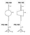
- Fig. 10A is another plan view illustrating a location of an infiltrative holding member (a porous material) relative to a transmission path.
- Fig. 10B is a graph showing an electric field distribution of THz wave propagating along the transmission path in Fig. 10A.
- Fig. 10C is another plan view illustrating a location of an infiltrative holding member (a porous material) relative to a transmission path.
- Fig. 10D is a graph showing an electric field distribution of THz wave propagating along the transmission path in Fig. 10C.
- a typical embodiment of apparatus for detecting information of a liquid object or sample includes a transmission path for transmitting THz wave therethrough, a THz-wave supplying unit for supplying THz wave to the transmission path through a coupling portion, and a THz-wave detecting unit for detecting the THz wave received from the transmission path via a couplingportion . Further, there is provided an infiltrative holding member for infiltration and holding of a liquid sample by capillary force, surface tension, etc. around the transmission path, or in a portion of a dielectric layer forming the transmission path.
- the infiltrative holding member is set at a location containing at least a portion in which an electric field distribution of the THz wave propagating along the transmission path extends.
- the detecting unit can obtain information of a change in a transmission condition of the THz wave transmitted through the transmission path caused by constituents of the liquid sample, its presence or absence, etc. Thus, information of the liquid sample can be acquired.
- the infiltrative holding member allows the liquid sample supplied by dripping or the like to be uniformly infiltrated therein by capillary force, etc. and held therein.
- the infiltrative holding member prevents the liquid sample from flowing out. Further, even in the event that the liquid sample dries and its solute precipitates in the infiltrative holding member, the solute is uniformly held in the infiltrative holding member.
- the wording of "uniformly" means that the sample gives a substantially uniform action to the THz wave used. In other words, when observing the sample at a positional resolution of about a wavelength of the THz wave used, the sample uniformly behaves for the THz wave.
- the interaction area between the THz wave propagating along the transmission path and the sample held in the infiltrative holding member is virtually always established in an appropriate manner. This is also assured by the fact that the liquid sample dripped on any position of the infiltrative holding member infiltrates into the entirety thereof virtually without fail. Accordingly, even quantitative detection of measuring the concentration of the sample, and the like can be accurately achieved.
- a constituent material of the infiltrative holding member is preferably a material having a high transmissivity for the THz wave used.
- the structure of the infiltrative holding member can be porous, fibrous, needle-like, or the like.
- the dimension (i.e., diameter of porosity, thickness of fiber or distance between fibers, or thickness of needle or distance between needles) of a fine structure thereof is desirably smaller enough than the wavelength of the THz wave used such that it does not scatter the radiation.
- the length of a longitudinal side of the infiltrative holding member is preferably less than the length of the transmission path.
- the reason therefor is that the interaction area between the liquid sample and the THz wave propagating along the transmission path is regulated by the size of the infiltrative holding member, since the liquid sample infiltrates almost into the entirety of the infiltrative holding member when the sample is dripped on the infiltrative holding member. Further, the electric field distribution of the propagating THz wave is exceedingly weak outside the transmission path, and hence this does not contribute to the detection.
- an infiltrative holding member with a longitudinal side longer than the transmission path can be used when a mechanism for preventing infiltration of the liquid sample beyond an area of the transmission path is formed. This is, for example, a mechanism for preventing infiltration beyond a desired region by pressing and crushing a portion of the infiltrative holding member with a frame member made of a non-infiltrative material.
- injecting means such as a micro-injector and a pipette capable of dripping a minute drop of liquid, can be used.
- the amount of a liquid sample supplied onto the infiltrative holding member exceeds its infiltrative holding ability, there is a possibility that the liquid sample comes out from the infiltrative holding member.
- a non-infiltrative member incapable of infiltration of the liquid sample e.g., a solid resin
- the volume of the liquid sample can be maintained at a predetermined value by wiping and removing over flowing liquid sample.
- the non-infiltrative member can be disposed adjacent to at least a portion (e.g., two sides, or four sides) of the infiltrative holding member to hold it at a predetermined location near the transmission path.
- the non-infiltrative member is disposed to adjoin two sides or surfaces of the infiltrative holding member extending along the transmission path.
- the non-infiltrative member is disposed to adjoin two sides or surfaces of the infiltrative holding member extending along the transmission path, and two sides or surfaces thereof extending in a direction traversing the transmission path.
- a spacing below a wavelength of the THz wave used can be formed between the infiltrative holding member and the non-infiltrative member.
- Theliquidsample can be supplied to the infiltrative holding member using the spacing as a guiding flow path.
- the infiltrative holding member can be brought into close contact with the non-infiltrative member.
- the non-infiltrative member When the non-infiltrative member is used, there is a case where an optical constant (refractive index, absorption coefficient, or the like) of the non-infiltrative member for the THz wave used is approximately equal to that of the infiltrative holding member, and there is a case where this is not so.
- the former case is a case where the detection is performed under a condition wherein THz wave propagating along the transmission path is not strongly reflected at a boundary between the infiltrative holding member and the non-infiltrative member.
- the latter case is a case where the reflection at the boundary between the infiltrative holding member and the non-infiltrative member is positively used, and a THz-wave resonator or THz-wave filter is constructed.
- the detection of the liquid sample is performed based on a change in properties of the THz-wave resonator or THz-wave filter caused by the supply of the liquid sample to the infiltrative holding member.
- the infiltrative holding member is disposed crossing its signal line, for example .
- the infiltrative holding member can be used as the dielectric between the signal line and the ground plane of the transmission path. It is preferable that the infiltrative holding member is disposed exclusively in the transmission path, or a nearby region where the electric field of the THz wave is relatively strongly distributed. Thereby, an effective interaction between the liquid sample and the THz wave can be achieved, and precision of the detection can be improved.
- the infiltrative holding member 92 such as a porous material
- the electric field present on this plane is distributed symmetrically about a geometrically symmetric center line of the signal line, as shown in Fig. 9B.
- the interaction between the sample in the infiltrative holding member and the THz wave propagating along the transmission path becomes strongest when the geometrically symmetric center line of the electric field is approximately aligned with the geometrically symmetric center line of the signal line.
- Fig. 9D, Fig. 10B and Fig. 10D also show electrical field distributions, respectively.
- the infiltrative holding members have various shapes, and the curve of the electrical field distribution varies depending on the shape of the infiltrative holding member.
- the infiltrative holding member is used as the dielectric between the signal line and the ground plane
- the electric field present on a plane parallel with the substrate and near the ground plane is distributed symmetrically about a geometrically symmetric center line parallel with the signal line. Accordingly, also in this case, the interaction between the sample in the infiltrative holding member and the THz wave propagating along the transmission path becomes strongest when the symmetrical center line of the electric field is approximately aligned with the symmetrical center line of the signal line.
- the electric field distribution of the THz wave along the transmission path is symmetrical about a center line parallel with the symmetrical center line of the transmissionpath.
- the interaction between the sample in the infiltrative holding member and the THz wave propagating along the transmission path becomes strongest when the symmetrical center line of the electric field distribution in a plane wherein the infiltrative holding member is set is approximately aligned with the center line of the infiltrative holding member.
- a geometrical gravity center line (a line passing a center of gravity) of the infiltrative holding member is approximately aligned with the symmetrical center line of the electric field distribution shown in Fig. 9D.
- a geometrical gravity center line of the electric field distribution is approximately aligned with the symmetrical center line (in the case of Figs. 10A and 10B), or the geometrical gravity center line (in the case of Figs. 10C and 10D) of the infiltrative holding members 102 and 103, respectively.
- element 101 depicts the signal line.
- Changes in transmission condition of the THz wave due to the sample infiltrated in the infiltrative holding member include a change in strength of the THz wave, a change in electric field amplitude or waveform of the THz wave, and the like.
- a time domain waveform of the THz wave is obtained, a spectrum of the THz wave transmitted through the transmission path can be acquired by Fourier-transforming the time domain waveform.
- the detection of the sample can be achieved based on the change in the spectrum.
- Refractive index, transmissivity, absorption coefficient, or the like can be obtained from those changes.
- information of the sample such as its identification, can be obtained.
- the infiltrative holding member preferably has a high and uniform transmissivity over the overall frequency of the THz wave propagating the transmission path. Since the frequency range of the THz wave propagating the transmission path depends on properties of a THz-wave generating source and the structure of the transmission path, actually required characteristics of a high and uniform transmissivity vary depending on cases.
- a manner of arrangement of the infiltrative holding member on the transmission path varies depending on whether the structure (a structure determining the effective dielectric constant, and the like) of the infiltrative holding member is isotropic or anisotropic for the THz wave propagating the transmission path. Further, the manner of arrangement of the infiltrative holding member on the transmission path varies depending on whether the liquid sample infiltrates in the infiltrative holding member in an isotropic or anisotropic fashion. More specifically, when the infiltrative holding member is isotropic, the infiltrative holding member can be set on the transmission path without considering its arrangement direction, and accordingly it can be arranged easily.
- the infiltrative holding member When the infiltrative holding member is anisotropic, the infiltrative holding member needs to be set on the transmission path, for example, with the characteristic direction of the infiltrative holding member being aligned with the extending direction of the transmission path, or a direction perpendicular thereto. Thereby, reproducibility of the detection of the liquid sample can be improved.
- porous materials with a granular or sponge structure formed of polypropylene, polysulfone, nylon, and polyether sulfone. Theseexamples are also isotropic infiltrative holding members.
- the porous material with a granular structure is a material in which a large number of fine particles disperse and are in contact with each other at point or surface.
- the porous material with a sponge structure is a material in which a large number of fine porosities disperse in a background material.
- a porous material with a granular structure in which a large number of fine particles disperse in an isotropic fashion (i.e., the charging rate of fine particles is substantially constant in every unit region), and which includes substantially no fibrous structure, is a preferable isotropic infiltrative holding member.
- a porous material with a sponge structure in which a large number of fine porosities disperse in an isotropic fashion (i.e., the volumetric rate of fine porosities is substantially constant in every unit region), and which includes substantially no fibrous structure, is a preferable isotropic infiltrative holding member.
- Inventors of the present invention performed the following experiment to obtain transmissivities of various porous materials.
- the detection was conducted by a so-called terahertz time-domain spectroscopy in which THz-wave pulses are generated from a photoconductive antenna, the THz-wave pulses are transmitted in a space, and the THz-wave pulses are detected by another photoconductive antenna.
- a sheet porous material is arranged in a transmission path of the THz-wave pulses, to obtain the transmissivity of the porous material.
- every porous material exhibits a preferable transmissivity.
- the porous materials with a granular or sponge structure formed of polypropylene, polysulfone, nylon, and polyethersulfone exhibits the following result.
- the transmissivity for THz wave at 2. 0 THz is above 90 percent, and a value ⁇ ' defined by the following formula (1) showing a uniformity of the transmissivity is above 20 (see the following Tables 1-1 and 1-2).
- the transmissivity is an amplitude transmittance defined by a ratio of an absolute value of amplitude of THz wave after transmission through the porous material relative to that before transmission through the porous material.
- v' T M - 1 / T L - T H
- v' is equal to a value obtained by dividing a value (which is obtained by subtracting 1 (one) from a transmissivity T M at a frequency near a center between uppermost frequency and lowermost frequency of THz wave used for measurement) by a difference between a transmissivityT H at the uppermost frequency and a transmissivity T L at the lowermost frequency, and taking an absolute value of this quotient.
- This value exhibits a degree of uniformity of the transmissivity over a frequency range.
- the frequency dependency of the transmissivity decreases. For example, at an extreme where the value v' is infinite, the value v' is independent of the frequency.
- the indication of uniformity of the transmissivity by the formula (1) is defined with reference to Abbe's number used in the field of optical material for showing the frequency dependency of a refractive index.
- the value v' will be referred to as a transmissivity Abbe's number.
- Table 1-1 main material of membrane filter amplitude transmissivity porosity diameter (micron) thickness (micron) use 0.5 THz 1.0 THz 2.0 THz polypropylene 100 98 96 0.45 114 solution and solvent usable Polysulfone 97 97 100 0.45 145 sterilization and filtration of living object and medicine polyethersulfone 98 96 100 0.45 140 sterilization and filtration of living object and medicine Nylon 97 96 95 0.45 127 suitable for organic solvent polyvinyliden-difluoride 98 96 84 0.45 147 suitable for protein and nucleic acid nitro cellulose 97 91 85 0.2 145 western transfer Cellulose 95 89 70 20 to 25 210 for analysis of Al, etc. glass fiber 98 90 80 1.6 260 monitoring of atmospheric pollution cellulose-mixed-ester 98 95 88 0.8 152 Microbioassay quartz fiber 98 99 82 450 atomic absorption analysis and emission spectroscopy
- the above granular or sponge structure can be distinguished from a non-granular or non-sponge structure by the following criteria.
- the sheet porous material can be deemed to have a granular or sponge structure when a spread of the dripped droplet is approximately circular.
- the sheet porous material cannot be deemed to have a granular or sponge structure when a spread of the dripped droplet is non-circular, such as elliptical.
- the spread can be determined to be non-uniform when a value obtained by dividing a longer diameter by a shorter diameter of the ellipse or the like is over 1.11. Therefore, with respect to boundary structures between the granular or sponge structure and the non-granular or non-sponge structure, the porous material can be deemed to have a granular or sponge structure if the spread shows the above value of less than 1.11.
- the porous materials with a granular or sponge structure formed of polypropylene, polysulfone, nylon, andpolyethersulfone have a relatively wide range over which the transmissivity is high for THz wave, and can be used as a preferable infiltrative holding material.
- a porous material with a granular or sponge structure formed of material having a high transmissivity for THz wave is also preferable even if the material is other than the above-stated polypropylene, polysulfone, nylon, and polyethersulfone.
- Such a porous material is considered to have a relatively high transmissivity, and a large uniformity of the transmissivity for THz wave.
- the principal object of the infiltrative holding member is to hold the liquid sample or object. Therefore, the infiltrative holding member is not necessarily a porous material with a granular or sponge structure formed of the above-stated polypropylene, polysulfone, nylon, or polyethersulfone.
- the actual frequency range of generated or detected THz wave can be without a range between 0.5 THz and 2.0 THz described in the Tables 1-1 and 1-2 because of the structure of the transmission path and properties of the THz-wave generator. Accordingly, it is permissible to use a material having a sufficiently high and uniform transmissivity for THz wave in an actual frequency range.
- the above-discussed porous material with a granular or sponge structure has an isotropic structure, so that it can be advantageously set on the transmission path without considering its arrangement direction.
- the porous material with a fibrous structure can improve reproducibility of the detection when it is set on the transmission path, for example, with its fibrous direction being aligned with the extending direction of the transmission path, or a direction perpendicular thereto.
- the liquid sample is dripped on the porous material with a fibrous structure, the sample is likely to infiltrate in an elliptical form. Therefore, when a longer-diameter direction of the ellipse is aligned with the extending direction of the transmission path, it is possible to achieve an effective interaction between THz wave and the liquid sample, and improve sensitivity of the detection.
- a ground of the transmission path is a metal plane 12 formed on a substrate 11 by vacuum evaporation or the like.
- the substrate 11 is, for example, a silicon substrate.
- the metal plane 12 is made of, for example, 500 ⁇ thin titanium and 3000 ⁇ thin gold.
- two LT (low-temperature)-GaAs layers 13a and 13b are formed by epitaxial lift-off or the like.
- a dielectric layer 14 relatively transparent for THz wave is formed on the LT-GaAs layers 13a and 13b.
- the dielectric layer 14 is made of, for example, BCB (benzocyclobutene).
- the thickness of the dielectric layer 14 is 5 microns, for example. A portion of the dielectric layer 14 is removed, and the LT-GaAs layers 13a and 13b are partly exposed.
- a metal line (a signal line) 15 is formed extending with a width of about 5 microns to 10 microns, and a longitudinal length of about 1 mm. Gaps 16a and 16b of about 5 microns to 10 microns are formed in two areas along the metal line 15. Electrodes 18a, 18b, 18c, and 18d are provided at end portions of the metal line 15.
- a transmission path 101 is constructed to extend in the extending direction of the metal line 15.
- a porous material 17 is disposed on the metal line 15.
- the porous material 17 is an infiltrative holding member for holding a liquid sample by capillary force and the like.
- a rectangular membrane filter is used as the porous material 17.
- the porous material 17 is set by bonding adhesive whose loss for THz wave is small, or by pressing it against the transmission path 101 with another member. A method of pushing the porous material 17 against the transmission path 101 with a resin plate (non-infiltrative member) 19 will be described.
- a hole is formed in the polystyrene plate 19 having a thickness of about 1 mm, and the porous material 17 with an outer size slightly larger than the hole is set covering the hole therewith, using bonding adhesive or the like.
- the polystyrene plate 19 is disposed such that the porous material 17 crosses the metal line 15 at a location between the two LT-GaAs layers 13a and 13b.
- the symmetrical center line of the porous material 17 is approximately aligned with the line 15.
- interaction between the liquid sample held in the porous material 17 and THz wave propagating along the transmission path 101 becomes stronger when the symmetrical center line of the porous material 17 is approximately aligned with the line 15. Further, it is preferable to bring the porous material 17 into contact with the line 15 since the above interaction increases.
- a marker (alignment mark) 100 can be provided at a portion of the porous material 17 or polystyrene plate 19, and a portion of the dielectric layer 14 for the purpose of achieving such an accurate arrangement that the symmetrical center line of the porous material 17 is approximately aligned with the line 15.
- the refractive index of the polystyrene plate 19 for THz wave is preferably close to that of the porous material 17. This is because if those refractive indices are largely different, reflection and the like due to impedance mismatch may occur at the boundary.
- a membrane filter (a product by Nihon Pall Ltd.; product No. 60172) formed of hydrophilic polyethersulfone with an average porosity diameter of 0.45 micron can be used as the porous material 17, and a polystyrene plate coated with hydrophobic foamy styrene can be used as the polystyrene plate 19.
- the refractive index of the porous material 17 is about 1.2
- the refractive index of the polystyrene plate 19 is from about 1.05 to about 1.1.
- the width of the rectangular porous material 17 is approximately over three times as large as the width of the line 15.
- the transmission path 101 for transmitting THz wave therethrough is composed of the metal plane 12, the dielectric layer 14 and the line 15.
- the electric field of propagating THz wave is strongly present within a region having a width that is about three times as large as the width of the line 15. Therefore, when the width of the porous material 17 is approximately set over three times as large as the width of the line 15, the interaction between the sample held in the porous material 17 and the propagating THz wave increases.
- the width of the porous material 17, however, can be made much larger in the light of fabrication convenience.
- As for the longitudinal length of its side it is preferably below the length of the transmission path.
- length, width, and thickness of the porous material 17 are, for example, about 0.6 mm, about 0.4 mm, and about 150 microns, respectively.
- the average porosity diameter of the porous material 17 is, for example, 0.5 micron. Further, the porous material 17 is formed of a material with a high transmissivity for THz wave (e.g., hydrophilic polyethersulfone).
- Two electrodes 18a and 18c; 18b and 18d are provided at end portions of the line 15, respectively.
- a voltage of about 10 V is applied through the electrode 18a in the THz-wave supplying unit, and the electrode 18b in the THz-wave detecting unit is connected to a signal amplifier 110.
- the other electrodes 18c and 18d are connected to the ground.
- the end portions of the line 15 act as a coupler for coupling the THz wave from the supplying unit to the transmission path, and a coupler for coupling the THz wave from the transmission path to the detecting unit, respectively.
- the gap 16a of the THz-wave supplying unit is illuminated with femtosecond (fsec) laser light to generate THz wave, and the THz wave is transmitted toward the gap 16b of the THz-wave detecting unit through the line 15.
- fsec femtosecond
- the THz wave interacts with the sample infiltrated in the porous member 17.
- the gap 16b of the THz-wave detecting unit is illuminated with the fsec laser, and the THz wave transmitted through the line 15 is detected through the signal amplifier 110.
- the liquid sample such as DNA solution
- the liquid sample is dripped and infiltrated in the porous member 17 using a micro-injector or the like.
- the liquid sample is infiltrated and held in the porous member 17 by capillary force and the like.
- the transmission condition of the THz wave detected by the detecting unit is changed (e.g., attenuated) by the sample held in the porous member 17.
- Information of the sample can be thus acquired from the spectrum or the like based on the above change
- Fig. 2 illustrates a peripheral optical system which is preferably used by the above detecting apparatus.
- fsec pulse laser light emitted from a mode-locked Ti:sapphire laser (fsec laser) 21 is split by a beam splitter 26.
- One laser light is condensed and illuminated on the gap 16a of the THz-wave supplying unit illustrated in Fig. 1, to which the voltage is applied.
- the other laser light is transmitted through a time delay optical system 22 by using mirrors 27, and then condensed and illuminated on the gap 16b of the THz-wave detecting unit of Fig. 1, which is connected to the signal amplifier 110.
- the interval between gaps 16a and 16b in the detecting apparatus 24 is exceedingly narrow (e.g., about 1 nm). Accordingly, it is preferable to re-collect the split laser light pulses prior to the above condensation and illumination, and project the re-collected light pulses on the gaps through a single object lens 23 or the like, respectively.
- the time-domain waveform of the THz wave transmitted through the transmission path 101 can be obtained when the time delay system 22 is moved back and forth. Fourier transformation of the obtained time-domain waveform brings forth the spectrum of THz wave whose transmission condition is changed according to characteristics, presence or absence, or the like of the sample. Information of the sample can be thus acquired.
- the porous material is used as the infiltrative holding member, but the fibrous material and the needle-like material can also be used.
- the porous material 17 is set on the transmission path using the polystyrene plate (non-infiltrative member) 19 in the above description.
- the infiltrative holding member can be set directly on the transmission path by bonding adhesive, or thermal pressure bonding.
- the dielectric of the transmission path can be made of a material, such as a porous material, capable of infiltration and holding of the liquid sample by capillary force and the like.
- the transmission path can also be formed by strip line, coplanar strip line, coplanar waveguide, micro-coplanar strip line, slab line, slot line, or the like.
- the infiltrative holding member for infiltration and holding of the liquid sample is used. Therefore, the location of the liquid sample relative to the transmission path can be regulated accurately. Hence, even the quantitative detection, inspection and measurement of the sample, such as measurement of its concentration, can be precisely achieved in an improved reproducibility. Further, when the liquid sample is dripped and dried in the infiltrative holding member, the thickness of precipitated sample becomes uniform. The spread of the liquid sample in the infiltrative holding member remains unchanged each time the sample is dripped, and hence the volume of interaction between the sample and THz wave does not fluctuate.
- the desired amount of the liquid sample can be accurately set on the transmission path, or near a desired portion thereof, in each detection. Even the quantitative measurement can be readily carried out in a good reproducibility.
- a living object such as DNA
- a first embodiment will be described with reference to Figs. 1A to 1C.
- the first embodiment corresponds to the above-discussed embodiment.
- the porous material 17 attached to the polystyrene plate 19 is prepared, and set on the line 15.
- the above-noted membrane filterproducedbyNihon Pall Ltd. product No.60172
- the marker (alignment mark) 100 is preferably used. Accordingly, the porous material 17 can be set on a desired location relative to the line 15.
- DNA solution is dripped on the porous material 17 through a hole in the polystyrene plate 19 using a microinjector (e.g., a programmable microinjector IM-300 produced by NARISHIGE SCIENTIFIC INSTRUMENT LAB.).
- concentration of the DNA solution is, for example, 0.5 microgram/microliter.
- the dripped amount is, for example, 30 nl.
- the dripped DNA solution is infiltrated and held in the porous material 17, and reaches a contact interface between the signal line 15 and the porous material 17.
- the dripped amount is extremely little (e.g., 1 pl)
- the dripped DNA solution does not infiltrate into the overall porous material 17.
- the DNA solution is not sufficiently infiltrated in the porous material 17 due to too dense concentration, too high viscosity, or the like, the effective accomplishment cannot be obtained. In such a case, therefore, the solution should be appropriately thinned, for example.
- the concentration of the DNA solution in the porous material 17 can be increased by repetition of dripping and drying of the sample.
- the DNA solution dripped on the porous material is dried in room temperature. After that, the THz wave generated by the THz-wave supplying unit is transmitted through the transmission path 101 to detect, for example, the time-domain waveform of the THz wave, according to the method as described in the above embodiment.
- Fig. 3 shows exemplified spectra by Fourier-transforming time-domain waveforms of THz waves transmitted through the transmission path 101 and detected by the THz-wave detecting unit.
- the solid line a illustrates the exemplified spectrum of the THz wave detected before the DNA solution is dripped on the porous material 17
- the dotted line b illustrates the exemplified spectrum of the THz wave detected after the DNA solution is dripped and dried.
- Information of presence, quantity, and so forth of the DNA can be detected based on the difference of the THz-wave spectra detected before and after the drip of the sample, as illustrated in Fig. 3.
- the THz-wave spectrum detected after the drip of the sample can be obtained in a good reproducibility, so that accurate information of the sample can be acquired.
- the DNA solution is approximately uniformly held in the porous material 17 set on the transmission path 101. Accordingly, reproducibility is obtained in the quantitative measurement, and an accurate quantitative detection is guaranteed.
- the volume of the porous material 17 is about 0.6 mm (length in a direction parallel with the signal line 15) * 0.4mm (width in a direction perpendicular to the signal line 15)*0.15 mm (thickness) .
- the liquid sample therefore, can be concentrated in a region over which propagating THz wave is distributed relatively strongly. Thus, efficient and accurate detection can be achieved.
- a frame of the polystyrene plate (non-infiltrative member) 19 exists around the porous material 17.
- the liquid sample comes out of the porous material even if too much liquid sample is dripped beyond liquid holding capability of the porous material 17.
- the liquid sample over the volume defined by the polystyrene frame is dripped, excessive liquid sample can be wiped and removed.
- the distribution of the liquid sample can be effectively regulated.
- thedetection canbe repetitively performed by removing the used porous material 17 with the resin plate 19 and disposing an unused resin plate with a porous material on the same transmission path 101.
- the marker (alignment mark) 100 is provided, the relative positional relation between the line 15 and the porous material 17 can be stably established each time of the detection. The reproducibility can be thus assured.
- FIG. 4A to 4C A second embodiment of the present invention will be described referring to Figs. 4A to 4C.
- the porous material 42 is set crossing the line 41 in the detecting apparatus including the THz-wave supplying unit, the transmission path (microstrip line structure), and the detecting unit.
- two non-infiltrative members or polystyrene plates 43a and 43b are pressed against two sides (parallel with the line 41) of the porous material 42, respectively.
- the porous material 42 can be thus set.
- Other structures of the second embodiment are substantially the same as those of the first embodiment.
- reference numerals are omitted with respect to those elements.
- the polystyrene plate 43 is preferably slightly larger than the porous material 41 in the longitudinal direction (e.g., 1 mm*0.6 mm).
- Two polystyrene plates 43a and 43b are preferably spaced from each other by more than thrice the width of the line 41 (i.e., each plate is away from the center of the line 41 by more than 1.5 times the width thereof). The reason is that such arrangement can prevent an impedance change of the transmission path due to the presence of the polystyrene plate 43.
- the gap of the THz-wave supplying unit is illuminated with femtosecond (fsec) laser light to generate THz wave, and the THz wave is transmitted through the transmission path. After interaction with the sample in the porous material 42, the THz wave reaches the THz-wave detecting unit. Thus, the time-domain waveform and forth of the THz wave can be obtained.
- fsec femtosecond
- the porous material 42 is in direct contact with the line 41, and no intervening substance, such as adhesive, exists therebetween. Reliable detection can be expected in this embodiment.
- the polystyrene plates 43a and 43b extend along the two sides of the porous material 42 as described above. Accordingly, even when much liquid sample beyond the liquid holding capability of the porous material 42 is dripped, virtually no liquid sample spreads toward a direction leaving from the line 41.
- the porous material 42 is an anisotropic porous material or fibrous material with properties that liquid therein is hard to spread in a direction parallel with the line 41, the liquid sample remains in the porous material 42. Accordingly, a relatively large liquid sample can be dripped at a time. Thus, the distribution of the liquid sample can be more effectively regulated.
- FIG. 5A to 5C A third embodiment of the present invention will be described referring to Figs. 5A to 5C.
- the porous material 52 is set crossing the line 51 by bonding or the like.
- adhesive such as BCB and photoresist
- the alignment mark can be provided for alignment at the time of bonding.
- the number of elements can be reduced.
- Other structures of the third embodiment are substantially the same as those of the first embodiment. Also in Figs. 5A to 5C, reference numerals are omitted with respect to those elements.
- the gap of the THz-wave supplying unit is illuminated with femtosecond (fsec) laser light to generate THz wave, and the THz wave is transmitted through the transmission path. After interaction with the sample in the porous material 52, the THz wave reaches the THz-wave detecting unit.
- fsec femtosecond
- a fourth embodiment of the present invention will be described referring to Figs. 6A to 6C.
- a hole is formed in the polystyrene plate 63 having a thickness of about 1 mm, and the porous material 62 with an outer size slightly larger than the hole is set covering the hole therewith, using bonding adhesive or the like.
- the polystyrene plate 63 is the non-infiltrative member of resin having a high transmissivity for THz wave.
- the size of the hole is about 0.4 mm*0.3 mm, and the size of the porous material 62 is 0.6mm * 0.4 mm, for example.
- Element 61 represents a metal line (signal line).
- Other structures of the fourth embodiment are substantially the same as those of the first embodiment. Also in Figs. 6A to 6C, reference numerals are omitted with respect to those elements.
- a flow path 64 can be formed in the polystyrene plate 63 surrounding the porous material 62, as illustrated in Figs. 6A to 6C.
- the flow path 64 extends to the side of the polystyrene plate 63.
- the size of the cross section of the flow path 64 is about 0.05 mm*0.5 mm.
- the liquid sample is guided through an inlet port of the flow path 64 in the side of the polystyrene plate 63.
- the liquid sample dripped in the inlet port of the flow path 64 by the micro-injector or the like reaches the porous material 62 due to capillary force and so forth of the flow path 64.
- the liquid sample is infiltrated and held in the porous material 62 due to its capillary force and so forth.
- the flow path 64 can be connected to a reservoir or the like for storing the liquid sample.
- the capillary of the micro-injector need not be accurately aligned with the porous material 62 at the time of dripping the liquid sample, so the sample can be readily introduced the porous material 62. Further, the possibility of damaging the porous material or the transmission path with the capillary of the injector can be reduced.
- the THz wave is transmitted through the transmission path. After interaction with the sample in the porous material 62, the THz wave reaches the THz-wave detecting unit.
- the time-domain waveform of the THz wave can be obtained, for example.
- a second resin layer 73 is formed on a BCB layer 71 in the detecting apparatus including the THz-wave supplying unit, the transmission path (microstrip line structure), and the detecting unit.
- a hole 73 is formed in a portion of the second resin layer 73 by plasma etching or the like.
- the second resin layer (non-infiltrative member) 73 is formed of a material (e.g., BCB) that cannot infiltrate and hold the liquid sample therein.
- the second resin layer 73 can be formed of photoresist, and the hole 74 can be formed by photolithography or the like.
- the size of the hole 74 is about the same as or slightly larger than the size of the porous material 75.
- the porous material 75 is set in the hole 74.
- a gap can be formed between the porous material 75 and the edge of the hole 74.
- the porous material 75 can be in contact with the edge of the hole 74.
- the thickness of the second resin layer 73 can be larger or smaller than the thickness of the porous material 75.
- the porous material 75 is set in the hole 74 with two sides of the porous material 75 parallel with the line 72 being bonded by adhesive or the like.
- Other structures of the fifth embodiment are substantially the same as those of the first embodiment. Also in Fig. 7A to 7C, reference numerals are omitted with respect to those elements.
- the non-infiltrative member and the flow path as described in the third and fourth embodiments can be fabricated integrally. Therefore, the number of the elements can be reduced in the fifth embodiment.
- the ground of the transmission path is a metal plane 82 formed on a substrate 81 by vacuum evaporation or the like.
- the substrate 81 is, for example, a silicon substrate.
- the metal plane 82 is made of, for example, 500 ⁇ thin titanium and 3000 ⁇ thin gold.
- two LT-GaAs layers 83a and 83b are formed by epitaxial lift-off or the like.
- the dielectric layer 86 transparent for THz wave is formed on the metal plane 82. Windows are then formed in portions on the two LT-GaAs layers 83a and 83b, and a portion therebetween.
- the porous material 84 is set in the window formed on the two LT-GaAs layers 83a and 83b by thermal pressure bonding, adhesive bonding, or the like.
- the window in the resin layer 86 is slightly larger than the porous material 84 so that the liquid sample can be supplied through the side of the porous material 84.
- the porous material 84 is beforehand processed such that its surface opposite to the side of the substrate can be a smooth flat face with porosities thereon being packed. Alternatively, a resin film or the like is attached on the above surface of the porous material 84.
- the metal line 85 is formed on the surface of the above structure by vacuum evaporation or the like.
- the metal plane 82, the porous material 84 and the line 85 constitute the transmission path of the microstrip line type.
- the porous material 84 serves as the dielectric layer of the transmission path, too.
- Other structures of the sixth embodiment are substantially the same as those of the first embodiment. Also in Figs. 8A to 8C, reference numerals are omitted with respect to those elements.
- a glass capillary 86 is placed near the side of the porous material 84 to supply the liquid sample thereby.
- the liquid sample is thus infiltrated in the porous material 84.
- the flow path can be used in place of the glass capillary.
- the porous material 84 is provided in the dielectric layer of the transmission path, so that the liquid sample can be supplied to a predetermined location in a strong electric field distribution with a predetermined volume. Also in the sixth embodiment, the THz wave is transmitted through the transmission path. After effective interaction with the sample in the porous material 84, the THz wave reaches the THz-wave detecting unit. Thus, the time-domain waveform of the THz wave can be accurately obtained, for example.
- a seventh embodiment will be described.
- the liquid sample infiltrated in the porous material is cooled and frozen.
- the liquid sample containing volatile liquid is infiltrated in the porous material, the liquid evaporates with time, and only non-volatile constituent remains in the porous material.
- the result of detection of the liquid sample varies with time since the evaporation proceeds with time. Further, time to be required for the evaporation and moisture content of the sample after the evaporation vary depending on ambient conditions, such as temperature and humidity of a place where the liquid sample exists.
- the liquid sample infiltrated in the porous material is cooled and frozen. Freezing is performed at such a timing that the condition of the sample to be detected cannot vary with time.
- the freezing can be conducted by a method of blowing cold (e.g., coolant and liquid nitrogen) on the measurement sample to directly freeze the sample, or a method of cooling the transmission path to indirectly freeze the sample using a Peltier device or the like, for example.
- the porous material such as the membrane filter, also serves as a heat insulating material for preventing heat from flowing into the frozen sample from outside.
- This embodiment can be employed for detection of a material contained in liquid from a living object. For example, sweat or blood is infiltrated and frozen in the porous material, and alcohol, sugar or the like therein is measured. Further, it is possible to infiltrate and freeze, in the porous material, a volatile liquid containing fine particles whose diameter are below the porosity diameter of the porous material, and detect such particles.
- a detecting apparatus for detecting information of a liquid object or sample includes a transmission path, a THz wave supplying unit, a THz wave detecting unit, and an infiltrative holding member for infiltration and holding of a liquid object.
- the supplying unit supplies an electromagnetic wave in a frequency range between 30 GHz and 30 THz to the transmission path.
- the detecting unit detects the THz wave transmitted through the transmission path.
- the infiltrative holding member is set at a location containing at least a portion in which an electric field distribution of the THz wave propagating along the transmission path extends.
Landscapes
- Physics & Mathematics (AREA)
- Health & Medical Sciences (AREA)
- Biochemistry (AREA)
- Life Sciences & Earth Sciences (AREA)
- Chemical & Material Sciences (AREA)
- Analytical Chemistry (AREA)
- General Health & Medical Sciences (AREA)
- General Physics & Mathematics (AREA)
- Immunology (AREA)
- Pathology (AREA)
- Spectroscopy & Molecular Physics (AREA)
- Electromagnetism (AREA)
- Toxicology (AREA)
- Investigating Or Analysing Materials By Optical Means (AREA)
- Investigating Or Analyzing Materials By The Use Of Electric Means (AREA)
Abstract


Description
- The present invention relates to a detecting apparatus and method for detecting information, such as characteristics, identification, concentration, and presence or absence, of a liquid object or sample, by using an electromagnetic wave. Particularly, the present invention relates to a detecting apparatus and method using an electromagnetic wave at a frequency or frequencies including at least a portion of a frequency range from 30 GHz to 30 THz. The electromagnetic wave including at least a component in the above frequency range is called a THz wave in this specification.
- In recent years, techniques using a THz wave have been energetically researched and developed. In particular, photon energy of a THz wave is approximately equal to energies of molecular skeleton vibration and intermolecular action of material, and hence, techniques using a THz wave are employed in analysis of material that uses spectra, etc. obtained by the spectroscopic method.
- In the above situation, "APPLIED PHYSICS LETTERS/Vol.80, No.1, 2002, p.154" discloses a proposal in which a THz-wave transmission path is formed on a substrate, DNA water solution is dripped and dried on the transmission path, and analysis of the DNA is carried out by detecting a change in a THz-wave transmission property of the transmission path. The proposal uses the fact that a dielectric constant of single-stranded DNA for the THz wave differs from that of double-stranded DNA, and shows that single-stranded DNA and double-stranded DNA can be separately identified based on a difference in the THz-wave transmission property of the transmission path.
- As stated above, when optical characteristics of material, such as an absorption coefficient, complex refractive index, and the like, are obtained by detecting a change in a transmission condition of a THz wave used, analysis, detection, identification, etc. of the material can be conducted. In the method of the above reference, however, no means is used for dripping a liquid sample onto the transmission path in an improved controllability, and accordingly it is typically not easy to accurately drip the sample on the transmission path. The dripped liquid sample is likely to flow and spread, so a location of the dripped sample on the transmission path and an interaction area between the THz wave and the sample are not easy to appropriately regulate.
- It is therefore an object of the present invention to provide a detecting apparatus and method for detecting information of a liquid object or sample using THz wave.
- According to one aspect of the present invention, there is provided a detecting apparatus for detecting information of a liquid object or sample, which includes a transmission path, a THz wave supplying unit, a THz wave detecting unit, and an infiltrative holding member for infiltration and holding of a liquid sample. The supplying unit supplies electromagnetic radiation in a frequency range between 30 GHz and 30 THz, or THz wave, to the transmission path. The detecting unit detects the THz wave transmitted through the transmission path. The infiltrative holding member is set at a location containing at least a portion in which an electric field distribution of the THz wave propagating along the transmission path extends.
- According to another aspect of the present invention, there is provided a detecting method for detecting information of a liquid object or sample, which includes a step of preparing an apparatus including a transmission path, a THz wave supplying unit, and a THz wave detecting unit, and a second of setting an infiltrative holding member for infiltration and holding of a liquid sample at a location containing at least a portion in which an electric field distribution of THz wave propagating along the transmission path extends. The supplying unit supplies electromagnetic wave in a frequency range between 30 GHz and 30 THz, or THz wave, to the transmission path. The detecting unit detects the THz wave transmitted through the transmission path. In the detecting method, the THz wave is supplied to the transmission path under a condition in which the liquid sample is infiltrated and held in the infiltrative holding member, and the THz wave transmitted through the transmission path is detected to detect information of the liquid sample.
- According to the present invention, the infiltrative holding member for infiltration and holding of a liquid object or sample is used, so the location of the dripped liquid object or sample on the transmission path and the interaction area between the THz wave and the liquid obj ect or sample can be accurately and precisely regulated.
- The features of the present invention will be more readily understood in connection with the following detailed description of the embodiments and examples of the invention in connection with the drawings.
- Fig. 1A is a plan view illustrating a first embodiment and example of a detecting apparatus and method according to the present invention, which uses an infiltrative holding member for infiltration and holding of a liquid sample.
- Fig. 1B is a cross-sectional view taken along line B-B' of Fig. 1A.
- Fig. 1C is a cross-sectional view taken along line A-A' of Fig. 1A.
- Fig. 2 is a view illustrating an optical system for supplying laser light to a transmission path of the detecting apparatus of the present invention.
- Fig. 3 is a graph showing exemplified spectra of a THz wave detected by a detecting unit of the detecting apparatus of the present invention.
- Fig. 4A is a plan view illustrating a second embodiment of a detecting apparatus and method according to the present invention, in which tow sides of an infiltrative holding member (a porous material) for infiltration and holding of a liquid sample are set by non-infiltrative members (resin plates).
- Fig. 4B is a cross-sectional view taken along line B-B' of Fig. 4A.
- Fig. 4C is a cross-sectional view taken along line A-A' of Fig. 4A.
- Fig. 5A is a plan view illustrating a third embodiment of a detecting apparatus and method according to the present invention, in which an infiltrative holding member (a porous material) for infiltration and holding of a liquid sample is set by bonding.
- Fig. 5B is a cross-sectional view taken along line B-B' of Fig. 5A.
- Fig. 5C is a cross-sectional view taken along line A-A' of Fig. 5A.
- Fig. 6A is a plan view illustrating a fourth embodiment of a detecting apparatus and method according to the present invention, in which a flow path is provided near an infiltrative holding member (a porous material) for infiltration and holding of a liquid sample.
- Fig. 6B is a cross-sectional view taken along line B-B' of Fig. 6A.
- Fig. 6C is a cross-sectional view taken along line A-A' of Fig. 6A.
- Fig. 7A is a plan view illustrating a fifth embodiment of a detecting apparatus and method according to the present invention, in which a hole is formed in a second resin layer, and an infiltrative holding member (a porous material) for infiltration and holding of a liquid sample is disposed in the hole.
- Fig. 7B is a cross-sectional view taken along line B-B' of Fig. 7A.
- Fig. 7C is a cross-sectional view taken along line A-A' of Fig. 7A.
- Fig. 8A is a plan view illustrating a sixth embodiment of a detecting apparatus and method according to the present invention, in which a dielectric layer includes an infiltrative holding member (a porous material) for infiltration and holding of a liquid sample.
- Fig. 8B is a cross-sectional view taken along line B-B' of Fig. 8A.
- Fig. 8C is a cross-sectional view taken along line A-A' of Fig. 8A.
- Fig. 9A is a plan view illustrating a location of an infiltrative holding member (a porous material) relative to a transmission path.
- Fig. 9B is a graph showing an electric field distribution of THz wave propagating along the transmission path in Fig. 9A.
- Fig. 9C is another plan view illustrating a location of an infiltrative holding member (a porous material) relative to a transmission path.
- Fig. 9D is a graph showing an electric field distribution of THz wave propagating along the transmission path in Fig. 9C.
- Fig. 10A is another plan view illustrating a location of an infiltrative holding member (a porous material) relative to a transmission path.
- Fig. 10B is a graph showing an electric field distribution of THz wave propagating along the transmission path in Fig. 10A.
- Fig. 10C is another plan view illustrating a location of an infiltrative holding member (a porous material) relative to a transmission path.
- Fig. 10D is a graph showing an electric field distribution of THz wave propagating along the transmission path in Fig. 10C.
- Embodiments and examples of a detecting apparatus and method for detecting information of a liquid object of the present invention will hereinafter be described with reference to the drawings.
- A typical embodiment of apparatus for detecting information of a liquid object or sample includes a transmission path for transmitting THz wave therethrough, a THz-wave supplying unit for supplying THz wave to the transmission path through a coupling portion, and a THz-wave detecting unit for detecting the THz wave received from the transmission path via a couplingportion . Further, there is provided an infiltrative holding member for infiltration and holding of a liquid sample by capillary force, surface tension, etc. around the transmission path, or in a portion of a dielectric layer forming the transmission path.
- The infiltrative holding member is set at a location containing at least a portion in which an electric field distribution of the THz wave propagating along the transmission path extends. In the above construction, the detecting unit can obtain information of a change in a transmission condition of the THz wave transmitted through the transmission path caused by constituents of the liquid sample, its presence or absence, etc. Thus, information of the liquid sample can be acquired.
- The infiltrative holding member allows the liquid sample supplied by dripping or the like to be uniformly infiltrated therein by capillary force, etc. and held therein. The infiltrative holding member prevents the liquid sample from flowing out. Further, even in the event that the liquid sample dries and its solute precipitates in the infiltrative holding member, the solute is uniformly held in the infiltrative holding member. Here, the wording of "uniformly" means that the sample gives a substantially uniform action to the THz wave used. In other words, when observing the sample at a positional resolution of about a wavelength of the THz wave used, the sample uniformly behaves for the THz wave.
- Accordingly, when the infiltrative holding member is accurately set, the interaction area between the THz wave propagating along the transmission path and the sample held in the infiltrative holding member is virtually always established in an appropriate manner.
This is also assured by the fact that the liquid sample dripped on any position of the infiltrative holding member infiltrates into the entirety thereof virtually without fail. Accordingly, even quantitative detection of measuring the concentration of the sample, and the like can be accurately achieved. - A constituent material of the infiltrative holding member is preferably a material having a high transmissivity for the THz wave used. The structure of the infiltrative holding member can be porous, fibrous, needle-like, or the like. The dimension (i.e., diameter of porosity, thickness of fiber or distance between fibers, or thickness of needle or distance between needles) of a fine structure thereof is desirably smaller enough than the wavelength of the THz wave used such that it does not scatter the radiation.
- The length of a longitudinal side of the infiltrative holding member is preferably less than the length of the transmission path. The reason therefor is that the interaction area between the liquid sample and the THz wave propagating along the transmission path is regulated by the size of the infiltrative holding member, since the liquid sample infiltrates almost into the entirety of the infiltrative holding member when the sample is dripped on the infiltrative holding member. Further, the electric field distribution of the propagating THz wave is exceedingly weak outside the transmission path, and hence this does not contribute to the detection. However, even an infiltrative holding member with a longitudinal side longer than the transmission path can be used when a mechanism for preventing infiltration of the liquid sample beyond an area of the transmission path is formed. This is, for example, a mechanism for preventing infiltration beyond a desired region by pressing and crushing a portion of the infiltrative holding member with a frame member made of a non-infiltrative material.
- As a method for infiltrating and holding a liquid sample in the infiltrative holding member, injecting means, such as a micro-injector and a pipette capable of dripping a minute drop of liquid, can be used.
- When the amount of a liquid sample supplied onto the infiltrative holding member exceeds its infiltrative holding ability, there is a possibility that the liquid sample comes out from the infiltrative holding member. In such a case, it is preferable to dispose a non-infiltrative member incapable of infiltration of the liquid sample (e.g., a solid resin) adjacent to a part or the entirety of the infiltrative holding member. Thereby, the liquid sample can be assuredly prevented from coming out from the infiltrative holding member, and the interaction area between the liquid sample and the THz wave can be accurately regulated.
- When the amount of dripped liquid sample exceeds the volume of a space formed by the non-infiltrative member, the volume of the liquid sample can be maintained at a predetermined value by wiping and removing over flowing liquid sample.
- The non-infiltrative member can be disposed adjacent to at least a portion (e.g., two sides, or four sides) of the infiltrative holding member to hold it at a predetermined location near the transmission path. In the case of two sides, for example, the non-infiltrative member is disposed to adjoin two sides or surfaces of the infiltrative holding member extending along the transmission path. In the case of four sides, the non-infiltrative member is disposed to adjoin two sides or surfaces of the infiltrative holding member extending along the transmission path, and two sides or surfaces thereof extending in a direction traversing the transmission path.
- When the non-infiltrative member is disposed adjacent to a portion or the entirety of the infiltrative holding member, a spacing below a wavelength of the THz wave used can be formed between the infiltrative holding member and the non-infiltrative member. Theliquidsample can be supplied to the infiltrative holding member using the spacing as a guiding flow path. In another configuration, the infiltrative holding member can be brought into close contact with the non-infiltrative member.
- When the non-infiltrative member is used, there is a case where an optical constant (refractive index, absorption coefficient, or the like) of the non-infiltrative member for the THz wave used is approximately equal to that of the infiltrative holding member, and there is a case where this is not so. The former case is a case where the detection is performed under a condition wherein THz wave propagating along the transmission path is not strongly reflected at a boundary between the infiltrative holding member and the non-infiltrative member. The latter case is a case where the reflection at the boundary between the infiltrative holding member and the non-infiltrative member is positively used, and a THz-wave resonator or THz-wave filter is constructed. In this latter case, the detection of the liquid sample is performed based on a change in properties of the THz-wave resonator or THz-wave filter caused by the supply of the liquid sample to the infiltrative holding member.
- When a metal microstrip line is used as the transmission path, the infiltrative holding member is disposed crossing its signal line, for example . In another case, the infiltrative holding member can be used as the dielectric between the signal line and the ground plane of the transmission path. It is preferable that the infiltrative holding member is disposed exclusively in the transmission path, or a nearby region where the electric field of the THz wave is relatively strongly distributed. Thereby, an effective interaction between the liquid sample and the THz wave can be achieved, and precision of the detection can be improved.
- For example, when the
infiltrative holding member 92, such as a porous material, is disposed on a plane parallel with a substrate including the signal line 91 (the transmission path), as illustrated in Fig. 9A, the electric field present on this plane is distributed symmetrically about a geometrically symmetric center line of the signal line, as shown in Fig. 9B. In such a case, the interaction between the sample in the infiltrative holding member and the THz wave propagating along the transmission path becomes strongest when the geometrically symmetric center line of the electric field is approximately aligned with the geometrically symmetric center line of the signal line. Where E(0)=1 is set in Fig. 9B, the interaction between the wave and the object can virtually occur down to a location of E(x)=1/e2. Therefore, the infiltrative holding member should be set in a range of E (x) > 1/e2. Needless to say, it is best to set the object at a location of E (0) =1 . Fig. 9D, Fig. 10B and Fig. 10D also show electrical field distributions, respectively. The infiltrative holding members have various shapes, and the curve of the electrical field distribution varies depending on the shape of the infiltrative holding member. - Further, also when the infiltrative holding member is used as the dielectric between the signal line and the ground plane, the electric field present on a plane parallel with the substrate and near the ground plane is distributed symmetrically about a geometrically symmetric center line parallel with the signal line. Accordingly, also in this case, the interaction between the sample in the infiltrative holding member and the THz wave propagating along the transmission path becomes strongest when the symmetrical center line of the electric field is approximately aligned with the symmetrical center line of the signal line.
- There is a case where two symmetrical center lines of the electric field distribution extending in directions parallel and perpendicular to the propagation direction of the THz wave exist. In such a case, it is preferable that the symmetrical center line of the electric field distribution parallel with the propagation direction is approximately aligned with the symmetrical center line of the infiltrative holding member.
- In general, observing in a plane parallel with the substrate constituting the transmission path, the electric field distribution of the THz wave along the transmission path is symmetrical about a center line parallel with the symmetrical center line of the transmissionpath. In such a case, the interaction between the sample in the infiltrative holding member and the THz wave propagating along the transmission path becomes strongest when the symmetrical center line of the electric field distribution in a plane wherein the infiltrative holding member is set is approximately aligned with the center line of the infiltrative holding member.
- Further, for example, when the
infiltrative holding member 93, such as a porous material, is asymmetrical as illustrated in Fig. 9C, it is preferable that a geometrical gravity center line (a line passing a center of gravity) of the infiltrative holding member is approximately aligned with the symmetrical center line of the electric field distribution shown in Fig. 9D. - Furthermore, for example, when the electric field distribution of the THz wave is asymmetrical as illustrated in Figs. 10A to 10D, it is preferable that a geometrical gravity center line of the electric field distribution is approximately aligned with the symmetrical center line (in the case of Figs. 10A and 10B), or the geometrical gravity center line (in the case of Figs. 10C and 10D) of the
infiltrative holding members element 101 depicts the signal line. - Changes in transmission condition of the THz wave due to the sample infiltrated in the infiltrative holding member include a change in strength of the THz wave, a change in electric field amplitude or waveform of the THz wave, and the like. When a time domain waveform of the THz wave is obtained, a spectrum of the THz wave transmitted through the transmission path can be acquired by Fourier-transforming the time domain waveform. The detection of the sample can be achieved based on the change in the spectrum. Refractive index, transmissivity, absorption coefficient, or the like can be obtained from those changes. Thus, information of the sample, such as its identification, can be obtained.
- The infiltrative holding member preferably has a high and uniform transmissivity over the overall frequency of the THz wave propagating the transmission path. Since the frequency range of the THz wave propagating the transmission path depends on properties of a THz-wave generating source and the structure of the transmission path, actually required characteristics of a high and uniform transmissivity vary depending on cases.
- A manner of arrangement of the infiltrative holding member on the transmission path varies depending on whether the structure (a structure determining the effective dielectric constant, and the like) of the infiltrative holding member is isotropic or anisotropic for the THz wave propagating the transmission path. Further, the manner of arrangement of the infiltrative holding member on the transmission path varies depending on whether the liquid sample infiltrates in the infiltrative holding member in an isotropic or anisotropic fashion. More specifically, when the infiltrative holding member is isotropic, the infiltrative holding member can be set on the transmission path without considering its arrangement direction, and accordingly it can be arranged easily. When the infiltrative holding member is anisotropic, the infiltrative holding member needs to be set on the transmission path, for example, with the characteristic direction of the infiltrative holding member being aligned with the extending direction of the transmission path, or a direction perpendicular thereto. Thereby, reproducibility of the detection of the liquid sample can be improved.
- As a material that has a high and uniform transmissivity as stated above, there are porous materials with a granular or sponge structure formed of polypropylene, polysulfone, nylon, and polyether sulfone. Theseexamples are also isotropic infiltrative holding members. The porous material with a granular structure is a material in which a large number of fine particles disperse and are in contact with each other at point or surface. The porous material with a sponge structure is a material in which a large number of fine porosities disperse in a background material. A porous material with a granular structure, in which a large number of fine particles disperse in an isotropic fashion (i.e., the charging rate of fine particles is substantially constant in every unit region), and which includes substantially no fibrous structure, is a preferable isotropic infiltrative holding member. Further, a porous material with a sponge structure, in which a large number of fine porosities disperse in an isotropic fashion (i.e., the volumetric rate of fine porosities is substantially constant in every unit region), and which includes substantially no fibrous structure, is a preferable isotropic infiltrative holding member.
- Inventors of the present invention performed the following experiment to obtain transmissivities of various porous materials. In this experiment, the detection was conducted by a so-called terahertz time-domain spectroscopy in which THz-wave pulses are generated from a photoconductive antenna, the THz-wave pulses are transmitted in a space, and the THz-wave pulses are detected by another photoconductive antenna. A sheet porous material is arranged in a transmission path of the THz-wave pulses, to obtain the transmissivity of the porous material.
- According to results of the above experiment, it can be understood that every porous material exhibits a preferable transmissivity. Particularly, the porous materials with a granular or sponge structure formed of polypropylene, polysulfone, nylon, and polyethersulfone exhibits the following result. The transmissivity for THz wave at 2. 0 THz is above 90 percent, and a value ν' defined by the following formula (1) showing a uniformity of the transmissivity is above 20 (see the following Tables 1-1 and 1-2). Here, the transmissivity is an amplitude transmittance defined by a ratio of an absolute value of amplitude of THz wave after transmission through the porous material relative to that before transmission through the porous material.
-

-
Table 1-1 main material of membrane filter amplitude transmissivity porosity diameter (micron) thickness (micron) use 0.5 THz 1.0 THz 2.0 THz polypropylene 100 98 96 0.45 114 solution and solvent usable Polysulfone 97 97 100 0.45 145 sterilization and filtration of living object and medicine polyethersulfone 98 96 100 0.45 140 sterilization and filtration of living object and medicine Nylon 97 96 95 0.45 127 suitable for organic solvent polyvinyliden-difluoride 98 96 84 0.45 147 suitable for protein and nucleic acid nitro cellulose 97 91 85 0.2 145 western transfer Cellulose 95 89 70 20 to 25 210 for analysis of Al, etc. glass fiber 98 90 80 1.6 260 monitoring of atmospheric pollution cellulose-mixed-ester 98 95 88 0.8 152 Microbioassay quartz fiber 98 99 82 450 atomic absorption analysis and emission spectroscopy -
Table1-2 main material of membrane filter property filtration rate uniformity (eccentricity) Abbe's number porosity property *1 polypropylene adsorption of low protein high 1.02 24.3 sponge-like polysulfone adsorption of low protein high 1.09 32.0 sponge-like polyethersulfone adsorption of low biomolecule high 1.00 47.5 granular nylon hydrophilicity of membrane itself high 1.01 47.5 sponge-like polyvinyliden-difluoride resistivity to biosolvent no filtration incapable of estimation 6.79 fibrous and granular nitro cellulose high coupling ability to protein and nucleic acid very low 1.16 7.50 fibrous cellulose for gelatin-like precipitant very high 1.11 3.52 fibrous glass fiber high filtration rate and holding of fine particles very high not clear 4.94 fibrous cellulose-mixed-ester high capture rate low 1.36 9.40 fibrous and sponge-like quartz fiber low background very high 1.12 6.13 fibrous Note: In the column of *1, 1.0 represents a true circle, polyvinyliden-difluoride is incapable of estimation since liquidcannot infiltrate inpolyvinyliden-difluoride, and glass fiber is not clear since the boundary of liquid infiltration area is not clear. - The above granular or sponge structure can be distinguished from a non-granular or non-sponge structure by the following criteria. Where a liquid droplet is dripped on a sheet porous material, the sheet porous material can be deemed to have a granular or sponge structure when a spread of the dripped droplet is approximately circular. The sheet porous material cannot be deemed to have a granular or sponge structure when a spread of the dripped droplet is non-circular, such as elliptical. In the case of a non-circular spread, the spread can be determined to be non-uniform when a value obtained by dividing a longer diameter by a shorter diameter of the ellipse or the like is over 1.11. Therefore, with respect to boundary structures between the granular or sponge structure and the non-granular or non-sponge structure, the porous material can be deemed to have a granular or sponge structure if the spread shows the above value of less than 1.11.
- To paraphrase the above, the porous materials with a granular or sponge structure formed of polypropylene, polysulfone, nylon, andpolyethersulfonehave a relatively wide range over which the transmissivity is high for THz wave, and can be used as a preferable infiltrative holding material.
- A porous material with a granular or sponge structure formed of material having a high transmissivity for THz wave is also preferable even if the material is other than the above-stated polypropylene, polysulfone, nylon, and polyethersulfone. Such a porous material is considered to have a relatively high transmissivity, and a large uniformity of the transmissivity for THz wave.
- The principal object of the infiltrative holding member is to hold the liquid sample or object. Therefore, the infiltrative holding member is not necessarily a porous material with a granular or sponge structure formed of the above-stated polypropylene, polysulfone, nylon, or polyethersulfone. Further, the actual frequency range of generated or detected THz wave can be without a range between 0.5 THz and 2.0 THz described in the Tables 1-1 and 1-2 because of the structure of the transmission path and properties of the THz-wave generator. Accordingly, it is permissible to use a material having a sufficiently high and uniform transmissivity for THz wave in an actual frequency range.
- The above-discussed porous material with a granular or sponge structure has an isotropic structure, so that it can be advantageously set on the transmission path without considering its arrangement direction. In contrast, the porous material with a fibrous structure can improve reproducibility of the detection when it is set on the transmission path, for example, with its fibrous direction being aligned with the extending direction of the transmission path, or a direction perpendicular thereto. Further, when the liquid sample is dripped on the porous material with a fibrous structure, the sample is likely to infiltrate in an elliptical form. Therefore, when a longer-diameter direction of the ellipse is aligned with the extending direction of the transmission path, it is possible to achieve an effective interaction between THz wave and the liquid sample, and improve sensitivity of the detection.
- The embodiments will be described in more detail with reference to Figs. 1A to 1C. In the detecting apparatus of the first embodiment, a ground of the transmission path is a
metal plane 12 formed on asubstrate 11 by vacuum evaporation or the like. Thesubstrate 11 is, for example, a silicon substrate. Themetal plane 12 is made of, for example, 500 Å thin titanium and 3000 Å thin gold. On themetal plane 12, two LT (low-temperature)-GaAs layers dielectric layer 14 relatively transparent for THz wave is formed on the LT-GaAs layers dielectric layer 14 is made of, for example, BCB (benzocyclobutene). The thickness of thedielectric layer 14 is 5 microns, for example. A portion of thedielectric layer 14 is removed, and the LT-GaAs layers dielectric layer 14, a metal line (a signal line) 15 is formed extending with a width of about 5 microns to 10 microns, and a longitudinal length of about 1 mm.Gaps metal line 15.Electrodes metal line 15. Atransmission path 101 is constructed to extend in the extending direction of themetal line 15. - A
porous material 17 is disposed on themetal line 15. Theporous material 17 is an infiltrative holding member for holding a liquid sample by capillary force and the like. For example, a rectangular membrane filter is used as theporous material 17. Theporous material 17 is set by bonding adhesive whose loss for THz wave is small, or by pressing it against thetransmission path 101 with another member. A method of pushing theporous material 17 against thetransmission path 101 with a resin plate (non-infiltrative member) 19 will be described. - In this method, a hole is formed in the
polystyrene plate 19 having a thickness of about 1 mm, and theporous material 17 with an outer size slightly larger than the hole is set covering the hole therewith, using bonding adhesive or the like. Thepolystyrene plate 19 is disposed such that theporous material 17 crosses themetal line 15 at a location between the two LT-GaAs layers porous material 17 is approximately aligned with theline 15. The reason therefor is as follows. With thetransmission path 101 of the microstrip line type as described above, the electric field of THz wave becomes stronger at a location as the location approaches the center of themetal line 15. Accordingly, interaction between the liquid sample held in theporous material 17 and THz wave propagating along thetransmission path 101 becomes stronger when the symmetrical center line of theporous material 17 is approximately aligned with theline 15. Further, it is preferable to bring theporous material 17 into contact with theline 15 since the above interaction increases. - A marker (alignment mark) 100 can be provided at a portion of the
porous material 17 orpolystyrene plate 19, and a portion of thedielectric layer 14 for the purpose of achieving such an accurate arrangement that the symmetrical center line of theporous material 17 is approximately aligned with theline 15. - The refractive index of the
polystyrene plate 19 for THz wave is preferably close to that of theporous material 17. This is because if those refractive indices are largely different, reflection and the like due to impedance mismatch may occur at the boundary. For example, a membrane filter (a product by Nihon Pall Ltd.; product No. 60172) formed of hydrophilic polyethersulfone with an average porosity diameter of 0.45 micron can be used as theporous material 17, and a polystyrene plate coated with hydrophobic foamy styrene can be used as thepolystyrene plate 19. In this case, the refractive index of theporous material 17 is about 1.2, and the refractive index of thepolystyrene plate 19 is from about 1.05 to about 1.1. - Preferably, the width of the rectangular
porous material 17 is approximately over three times as large as the width of theline 15. Thetransmission path 101 for transmitting THz wave therethrough is composed of themetal plane 12, thedielectric layer 14 and theline 15. With this transmission path of the microstrip line type, the electric field of propagating THz wave is strongly present within a region having a width that is about three times as large as the width of theline 15. Therefore, when the width of theporous material 17 is approximately set over three times as large as the width of theline 15, the interaction between the sample held in theporous material 17 and the propagating THz wave increases. The width of theporous material 17, however, can be made much larger in the light of fabrication convenience. As for the longitudinal length of its side, it is preferably below the length of the transmission path. In this embodiment, length, width, and thickness of theporous material 17 are, for example, about 0.6 mm, about 0.4 mm, and about 150 microns, respectively. - The average porosity diameter of the
porous material 17 is, for example, 0.5 micron. Further, theporous material 17 is formed of a material with a high transmissivity for THz wave (e.g., hydrophilic polyethersulfone). - Two
electrodes line 15, respectively. A voltage of about 10 V is applied through theelectrode 18a in the THz-wave supplying unit, and theelectrode 18b in the THz-wave detecting unit is connected to asignal amplifier 110. Theother electrodes line 15 act as a coupler for coupling the THz wave from the supplying unit to the transmission path, and a coupler for coupling the THz wave from the transmission path to the detecting unit, respectively. - In this embodiment, the
gap 16a of the THz-wave supplying unit is illuminated with femtosecond (fsec) laser light to generate THz wave, and the THz wave is transmitted toward thegap 16b of the THz-wave detecting unit through theline 15. On the way of transmission through the transmission path, the THz wave interacts with the sample infiltrated in theporous member 17. On the other hand, thegap 16b of the THz-wave detecting unit is illuminated with the fsec laser, and the THz wave transmitted through theline 15 is detected through thesignal amplifier 110. - The liquid sample, such as DNA solution, is dripped and infiltrated in the
porous member 17 using a micro-injector or the like. The liquid sample is infiltrated and held in theporous member 17 by capillary force and the like. The transmission condition of the THz wave detected by the detecting unit is changed (e.g., attenuated) by the sample held in theporous member 17. Information of the sample can be thus acquired from the spectrum or the like based on the above change - Fig. 2 illustrates a peripheral optical system which is preferably used by the above detecting apparatus. As illustrated in Fig. 2, fsec pulse laser light emitted from a mode-locked Ti:sapphire laser (fsec laser) 21 is split by a
beam splitter 26. One laser light is condensed and illuminated on thegap 16a of the THz-wave supplying unit illustrated in Fig. 1, to which the voltage is applied. The other laser light is transmitted through a time delayoptical system 22 by usingmirrors 27, and then condensed and illuminated on thegap 16b of the THz-wave detecting unit of Fig. 1, which is connected to thesignal amplifier 110. - The interval between
gaps apparatus 24 is exceedingly narrow (e.g., about 1 nm). Accordingly, it is preferable to re-collect the split laser light pulses prior to the above condensation and illumination, and project the re-collected light pulses on the gaps through asingle object lens 23 or the like, respectively. The time-domain waveform of the THz wave transmitted through thetransmission path 101 can be obtained when thetime delay system 22 is moved back and forth. Fourier transformation of the obtained time-domain waveform brings forth the spectrum of THz wave whose transmission condition is changed according to characteristics, presence or absence, or the like of the sample. Information of the sample can be thus acquired. - In the above discussion, the porous material is used as the infiltrative holding member, but the fibrous material and the needle-like material can also be used. Further, the
porous material 17 is set on the transmission path using the polystyrene plate (non-infiltrative member) 19 in the above description. The infiltrative holding member, however, can be set directly on the transmission path by bonding adhesive, or thermal pressure bonding. Furthermore, the dielectric of the transmission path can be made of a material, such as a porous material, capable of infiltration and holding of the liquid sample by capillary force and the like. - With respect to the structure and configuration of the transmission path, it is not limited to the above microstrip line. The transmission path can also be formed by strip line, coplanar strip line, coplanar waveguide, micro-coplanar strip line, slab line, slot line, or the like.
- In the above detecting apparatus and method, the infiltrative holding member for infiltration and holding of the liquid sample is used. Therefore, the location of the liquid sample relative to the transmission path can be regulated accurately. Hence, even the quantitative detection, inspection and measurement of the sample, such as measurement of its concentration, can be precisely achieved in an improved reproducibility. Further, when the liquid sample is dripped and dried in the infiltrative holding member, the thickness of precipitated sample becomes uniform. The spread of the liquid sample in the infiltrative holding member remains unchanged each time the sample is dripped, and hence the volume of interaction between the sample and THz wave does not fluctuate.
- In conventional apparatuses and methods, there is a possibility that the sample drop falls, and the interaction volume between the sample and THz wave changes when the transmission path is violently handled prior to sufficient drying of the sample, for example. In the above embodiment, such possibility can be eliminated.
- Thus, in the above embodiment, the desired amount of the liquid sample can be accurately set on the transmission path, or near a desired portion thereof, in each detection. Even the quantitative measurement can be readily carried out in a good reproducibility. For example, a living object, such as DNA, can be held in the infiltrative holding member with its three-dimensional configuration being unchanged even when the liquid sample is dried. Precise information of the sample can be acquired.
- Description will be made for more specific embodiments and examples. A first embodiment will be described with reference to Figs. 1A to 1C. The first embodiment corresponds to the above-discussed embodiment. In this embodiment, the
porous material 17 attached to thepolystyrene plate 19 is prepared, and set on theline 15. The above-noted membrane filterproducedbyNihon Pall Ltd. (product No.60172) is preferably used as theporous material 17 . When thepolystyrene plate 19 with theporous material 17 attached thereto is disposed on theline 15, the marker (alignment mark) 100 is preferably used. Accordingly, theporous material 17 can be set on a desired location relative to theline 15. - When the liquid sample is infiltrated into the
porous material 17 set on theline 15, DNA solution is dripped on theporous material 17 through a hole in thepolystyrene plate 19 using a microinjector (e.g., a programmable microinjector IM-300 produced by NARISHIGE SCIENTIFIC INSTRUMENT LAB.). The concentration of the DNA solution is, for example, 0.5 microgram/microliter. The dripped amount is, for example, 30 nl. The dripped DNA solution is infiltrated and held in theporous material 17, and reaches a contact interface between thesignal line 15 and theporous material 17. In the case the dripped amount is extremely little (e.g., 1 pl), there is a possibility that the dripped DNA solution does not infiltrate into the overallporous material 17. This substantially impedes effective accomplishment that the interaction region between the sample and THz wave is accurately regulated. Therefore, there is a need to drip an amount enough to achieve infiltration of the liquid sample in the entirety of theporous material 17. Further, also in the case the DNA solution is not sufficiently infiltrated in theporous material 17 due to too dense concentration, too high viscosity, or the like, the effective accomplishment cannot be obtained. In such a case, therefore, the solution should be appropriately thinned, for example. The concentration of the DNA solution in theporous material 17 can be increased by repetition of dripping and drying of the sample. - The DNA solution dripped on the porous material is dried in room temperature. After that, the THz wave generated by the THz-wave supplying unit is transmitted through the
transmission path 101 to detect, for example, the time-domain waveform of the THz wave, according to the method as described in the above embodiment. - Fig. 3 shows exemplified spectra by Fourier-transforming time-domain waveforms of THz waves transmitted through the
transmission path 101 and detected by the THz-wave detecting unit. In Fig. 3, the solid line a illustrates the exemplified spectrum of the THz wave detected before the DNA solution is dripped on theporous material 17, and the dotted line b illustrates the exemplified spectrum of the THz wave detected after the DNA solution is dripped and dried. Information of presence, quantity, and so forth of the DNA can be detected based on the difference of the THz-wave spectra detected before and after the drip of the sample, as illustrated in Fig. 3. In this embodiment, the THz-wave spectrum detected after the drip of the sample can be obtained in a good reproducibility, so that accurate information of the sample can be acquired. In contrast thereto, it is not easy for the conventional technique to stably drip the liquid sample on an appropriate location on the transmission path in a preferable reproducibility. Therefore, according to the conventional technique, the THz-wave spectrum detected after the drip of the sample cannot typically be obtained in a satisfactory reproducibility. - In the first embodiment, the DNA solution is approximately uniformly held in the
porous material 17 set on thetransmission path 101. Accordingly, reproducibility is obtained in the quantitative measurement, and an accurate quantitative detection is guaranteed. The volume of theporous material 17 is about 0.6 mm (length in a direction parallel with the signal line 15) * 0.4mm (width in a direction perpendicular to the signal line 15)*0.15 mm (thickness) . The liquid sample, therefore, can be concentrated in a region over which propagating THz wave is distributed relatively strongly. Thus, efficient and accurate detection can be achieved. - Further, in this embodiment, a frame of the polystyrene plate (non-infiltrative member) 19 exists around the
porous material 17. Hence, there is virtually no possibility that the liquid sample comes out of the porous material even if too much liquid sample is dripped beyond liquid holding capability of theporous material 17. When the liquid sample over the volume defined by the polystyrene frame is dripped, excessive liquid sample can be wiped and removed. Thus, the distribution of the liquid sample can be effectively regulated. - Furthermore, thedetectioncanbe repetitively performed by removing the used
porous material 17 with theresin plate 19 and disposing an unused resin plate with a porous material on thesame transmission path 101. When the marker (alignment mark) 100 is provided, the relative positional relation between theline 15 and theporous material 17 can be stably established each time of the detection. The reproducibility can be thus assured. - A second embodiment of the present invention will be described referring to Figs. 4A to 4C. Also in this embodiment, similar to the first embodiment, the
porous material 42 is set crossing theline 41 in the detecting apparatus including the THz-wave supplying unit, the transmission path (microstrip line structure), and the detecting unit. In the second embodiment, two non-infiltrative members orpolystyrene plates porous material 42, respectively. Theporous material 42 can be thus set. Other structures of the second embodiment are substantially the same as those of the first embodiment. In Figs. 4A to 4C, reference numerals are omitted with respect to those elements. - The polystyrene plate 43 is preferably slightly larger than the
porous material 41 in the longitudinal direction (e.g., 1 mm*0.6 mm). Twopolystyrene plates line 41 by more than 1.5 times the width thereof). The reason is that such arrangement can prevent an impedance change of the transmission path due to the presence of the polystyrene plate 43. - Also in the second embodiment, the gap of the THz-wave supplying unit is illuminated with femtosecond (fsec) laser light to generate THz wave, and the THz wave is transmitted through the transmission path. After interaction with the sample in the
porous material 42, the THz wave reaches the THz-wave detecting unit. Thus, the time-domain waveform and forth of the THz wave can be obtained. - In the second embodiment, the
porous material 42 is in direct contact with theline 41, and no intervening substance, such as adhesive, exists therebetween. Reliable detection can be expected in this embodiment. Further, thepolystyrene plates porous material 42 as described above. Accordingly, even when much liquid sample beyond the liquid holding capability of theporous material 42 is dripped, virtually no liquid sample spreads toward a direction leaving from theline 41. When theporous material 42 is an anisotropic porous material or fibrous material with properties that liquid therein is hard to spread in a direction parallel with theline 41, the liquid sample remains in theporous material 42. Accordingly, a relatively large liquid sample can be dripped at a time. Thus, the distribution of the liquid sample can be more effectively regulated. - A third embodiment of the present invention will be described referring to Figs. 5A to 5C. In this embodiment, the
porous material 52 is set crossing theline 51 by bonding or the like. For example, adhesive, such as BCB and photoresist, is applied on a peripheral portion of theporous material 52 near its two sides parallel with theline 51, and theporous material 52 is bonded on the transmission path crossing theline 51. The alignment mark can be provided for alignment at the time of bonding. In the third embodiment, the number of elements can be reduced. Other structures of the third embodiment are substantially the same as those of the first embodiment. Also in Figs. 5A to 5C, reference numerals are omitted with respect to those elements. - Also in the third embodiment, the gap of the THz-wave supplying unit is illuminated with femtosecond (fsec) laser light to generate THz wave, and the THz wave is transmitted through the transmission path. After interaction with the sample in the
porous material 52, the THz wave reaches the THz-wave detecting unit. Thus, the time-domain waveform of the THz wave can be obtained, for example. - A fourth embodiment of the present invention will be described referring to Figs. 6A to 6C. In this embodiment, a hole is formed in the
polystyrene plate 63 having a thickness of about 1 mm, and theporous material 62 with an outer size slightly larger than the hole is set covering the hole therewith, using bonding adhesive or the like. Thepolystyrene plate 63 is the non-infiltrative member of resin having a high transmissivity for THz wave. The size of the hole is about 0.4 mm*0.3 mm, and the size of theporous material 62 is 0.6mm*0.4 mm, for example.Element 61 represents a metal line (signal line). Other structures of the fourth embodiment are substantially the same as those of the first embodiment. Also in Figs. 6A to 6C, reference numerals are omitted with respect to those elements. - A
flow path 64 can be formed in thepolystyrene plate 63 surrounding theporous material 62, as illustrated in Figs. 6A to 6C. Theflow path 64 extends to the side of thepolystyrene plate 63. The size of the cross section of theflow path 64 is about 0.05 mm*0.5 mm. In this case, the liquid sample is guided through an inlet port of theflow path 64 in the side of thepolystyrene plate 63. The liquid sample dripped in the inlet port of theflow path 64 by the micro-injector or the like reaches theporous material 62 due to capillary force and so forth of theflow path 64. The liquid sample is infiltrated and held in theporous material 62 due to its capillary force and so forth. - The
flow path 64 can be connected to a reservoir or the like for storing the liquid sample. In such a structure, the capillary of the micro-injector need not be accurately aligned with theporous material 62 at the time of dripping the liquid sample, so the sample can be readily introduced theporous material 62. Further, the possibility of damaging the porous material or the transmission path with the capillary of the injector can be reduced. - Also in the fourth embodiment, similar to the first embodiment, the THz wave is transmitted through the transmission path. After interaction with the sample in the
porous material 62, the THz wave reaches the THz-wave detecting unit. Thus, the time-domain waveform of the THz wave can be obtained, for example. - A fifth embodiment of the present invention will be described referring to Figs. 7A to 7C. In this embodiment, a
second resin layer 73 is formed on aBCB layer 71 in the detecting apparatus including the THz-wave supplying unit, the transmission path (microstrip line structure), and the detecting unit. Ahole 73 is formed in a portion of thesecond resin layer 73 by plasma etching or the like. The second resin layer (non-infiltrative member) 73 is formed of a material (e.g., BCB) that cannot infiltrate and hold the liquid sample therein. Thesecond resin layer 73 can be formed of photoresist, and thehole 74 can be formed by photolithography or the like. - The size of the
hole 74 is about the same as or slightly larger than the size of theporous material 75. Theporous material 75 is set in thehole 74. A gap can be formed between theporous material 75 and the edge of thehole 74. In another configuration, theporous material 75 can be in contact with the edge of thehole 74. The thickness of thesecond resin layer 73 can be larger or smaller than the thickness of theporous material 75. Theporous material 75 is set in thehole 74 with two sides of theporous material 75 parallel with theline 72 being bonded by adhesive or the like. Other structures of the fifth embodiment are substantially the same as those of the first embodiment. Also in Fig. 7A to 7C, reference numerals are omitted with respect to those elements. - In the fifth embodiment, the non-infiltrative member and the flow path as described in the third and fourth embodiments can be fabricated integrally. Therefore, the number of the elements can be reduced in the fifth embodiment.
- A sixth embodiment will be described with reference to Figs. 8A to 8C. In the detecting apparatus of the sixth embodiment, the ground of the transmission path is a
metal plane 82 formed on asubstrate 81 by vacuum evaporation or the like. Thesubstrate 81 is, for example, a silicon substrate. Themetal plane 82 is made of, for example, 500 Å thin titanium and 3000 Å thin gold. On themetal plane 82, two LT-GaAs layers dielectric layer 86 transparent for THz wave is formed on themetal plane 82. Windows are then formed in portions on the two LT-GaAs layers porous material 84 is set in the window formed on the two LT-GaAs layers resin layer 86 is slightly larger than theporous material 84 so that the liquid sample can be supplied through the side of theporous material 84. Theporous material 84 is beforehand processed such that its surface opposite to the side of the substrate can be a smooth flat face with porosities thereon being packed. Alternatively, a resin film or the like is attached on the above surface of theporous material 84. - The
metal line 85 is formed on the surface of the above structure by vacuum evaporation or the like. Themetal plane 82, theporous material 84 and theline 85 constitute the transmission path of the microstrip line type. In this embodiment, theporous material 84 serves as the dielectric layer of the transmission path, too. Other structures of the sixth embodiment are substantially the same as those of the first embodiment. Also in Figs. 8A to 8C, reference numerals are omitted with respect to those elements. - In the above structure, a
glass capillary 86 is placed near the side of theporous material 84 to supply the liquid sample thereby. The liquid sample is thus infiltrated in theporous material 84. The flow path can be used in place of the glass capillary. - In this embodiment, the
porous material 84 is provided in the dielectric layer of the transmission path, so that the liquid sample can be supplied to a predetermined location in a strong electric field distribution with a predetermined volume. Also in the sixth embodiment, the THz wave is transmitted through the transmission path. After effective interaction with the sample in theporous material 84, the THz wave reaches the THz-wave detecting unit. Thus, the time-domain waveform of the THz wave can be accurately obtained, for example. - A seventh embodiment will be described. In the detecting apparatus of the seventh embodiment, the liquid sample infiltrated in the porous material is cooled and frozen. When the liquid sample containing volatile liquid is infiltrated in the porous material, the liquid evaporates with time, and only non-volatile constituent remains in the porous material. The result of detection of the liquid sample varies with time since the evaporation proceeds with time. Further, time to be required for the evaporation and moisture content of the sample after the evaporation vary depending on ambient conditions, such as temperature and humidity of a place where the liquid sample exists.
- To overcome such problem and acquire a stable result of detection, the liquid sample infiltrated in the porous material is cooled and frozen. Freezing is performed at such a timing that the condition of the sample to be detected cannot vary with time. The freezing can be conducted by a method of blowing cold (e.g., coolant and liquid nitrogen) on the measurement sample to directly freeze the sample, or a method of cooling the transmission path to indirectly freeze the sample using a Peltier device or the like, for example.
- At the time of freezing, the porous material, such as the membrane filter, also serves as a heat insulating material for preventing heat from flowing into the frozen sample from outside.
- This embodiment can be employed for detection of a material contained in liquid from a living object. For example, sweat or blood is infiltrated and frozen in the porous material, and alcohol, sugar or the like therein is measured. Further, it is possible to infiltrate and freeze, in the porous material, a volatile liquid containing fine particles whose diameter are below the porosity diameter of the porous material, and detect such particles.
- As described in the foregoing, according to the present invention, it is possible to provide devices using electromagnetic waves at frequency or frequencies in a range between 30 GHz and 30 THz.
- Except as otherwise disclosed herein, the various components shown in outline or in block form in the figures are individually well-known and their internal construction and operation are not critical either to the making or using of the present invention or to a description of the best mode of the invention.
- While the present invention has been described with respect to what is presently considered to be the embodiments and examples, it is to be understood that the invention is not limited to the disclosed embodiments and examples. The present invention is intended to cover various modifications and equivalent arrangements included within the spirit and the scope of the appended claims.
- This application claims priority from
Japanese Patent Application No.2006-108563, filed April 11, 2006 Japanese Patent Application No.2007-023610, filed February 2, 2007
A detecting apparatus for detecting information of a liquid object or sample includes a transmission path, a THz wave supplying unit, a THz wave detecting unit, and an infiltrative holding member for infiltration and holding of a liquid object. The supplying unit supplies an electromagnetic wave in a frequency range between 30 GHz and 30 THz to the transmission path. The detecting unit detects the THz wave transmitted through the transmission path. The infiltrative holding member is set at a location containing at least a portion in which an electric field distribution of the THz wave propagating along the transmission path extends.
Claims (11)
- A detecting apparatus for detecting information of a liquid object, the detecting apparatus comprising:a transmission path;an electromagnetic-wave supplying unit for supplying an electromagnetic wave in a frequency range between 30 GHz and 30 THz;an electromagnetic-wave detecting unit for detecting the electromagnetic wave transmitted through the transmission path; andan infiltrative holding member for infiltration and holding of the liquid object, the infiltrative holding member being set at a location containing at least a portion in which an electric field distribution of the electromagnetic wave propagating along the transmission path extends.
- The detecting apparatus according to claim 1, wherein the transmission path comprises a metal.
- The detecting apparatus according to claim 1, further comprising a non-infiltrative member, which is incapable of infiltrating the liquid object, and which is set partly or entirely surrounding the infiltrative holding member.
- The detecting apparatus according to claim 3, wherein a spacing, whose size is less than the wavelength of the electromagnetic wave supplied by the electromagnetic-wave supplying unit, is present between the infiltrative holding member and the non-infiltrative member.
- The detecting apparatus according to claim 1, wherein a geometrically symmetric center line, or a geometrical gravity center line of the infiltrative holding member is aligned with a geometrically symmetric center line, or a geometrical gravity center line parallel with a propagation direction of the electric field distribution of the electromagnetic wave propagating along the transmission path.
- The detecting apparatus according to claim 1, further comprising a marker for setting the infiltrative holding member relative to the transmission path.
- The detecting apparatus according to claim 1, wherein the infiltrative holding member comprises one of a porous material, a fibrous material, and a needle structure.
- A detecting method for detecting information of a liquid object, the detecting method comprising the steps of:infiltrating and holding the liquid object in an infiltrative holding member of an apparatus;supplying an electromagnetic wave in a frequency between 30 GHz and 30 THz into a transmission path of the apparatus under a condition in which the liquid object is infiltrated and held in the infiltrative holding member, which is set at a location containing at least a portion in which an electric field distribution of the electromagnetic wave propagating along the transmission path extends; anddetecting the electromagnetic wave transmitted through the transmission path to obtain information of the liquid object.
- The detecting method according to claim 8, wherein a non-infiltrative member, which is incapable of infiltrating the liquid object, is set partly or entirely surrounding the infiltrative holding member.
- The detecting method according to claim 8, wherein an injector is used to infiltrate and hold the liquid object in the infiltrative holding member.
- The detecting method according to claim 8, wherein the infiltrating and holding step further comprises cooling and freezing the liquid object in the infiltrative holding member.
Applications Claiming Priority (2)
| Application Number | Priority Date | Filing Date | Title |
|---|---|---|---|
| JP2006108563 | 2006-04-11 | ||
| JP2007023610A JP4898472B2 (en) | 2006-04-11 | 2007-02-02 | Inspection device |
Publications (2)
| Publication Number | Publication Date |
|---|---|
| EP1845364A2 true EP1845364A2 (en) | 2007-10-17 |
| EP1845364A3 EP1845364A3 (en) | 2010-02-10 |
Family
ID=38231128
Family Applications (1)
| Application Number | Title | Priority Date | Filing Date |
|---|---|---|---|
| EP20070105871 Withdrawn EP1845364A3 (en) | 2006-04-11 | 2007-04-10 | Detecting apparatus and method |
Country Status (4)
| Country | Link |
|---|---|
| US (2) | US7560695B2 (en) |
| EP (1) | EP1845364A3 (en) |
| JP (1) | JP4898472B2 (en) |
| CN (1) | CN101059454B (en) |
Cited By (9)
| Publication number | Priority date | Publication date | Assignee | Title |
|---|---|---|---|---|
| US9366620B2 (en) | 2011-06-01 | 2016-06-14 | Murata Manufacturing Co., Ltd. | Specimen measuring method |
| EP3102929A4 (en) * | 2014-02-05 | 2017-08-16 | Vayyar Imaging Ltd. | System devise and method for testing an object |
| US10288728B2 (en) | 2015-04-29 | 2019-05-14 | Vayyar Imaging Ltd | System, device and methods for localization and orientation of a radio frequency antenna array |
| US10290948B2 (en) | 2015-08-02 | 2019-05-14 | Vayyar Imaging Ltd | System and method for radio frequency penetration imaging of an object |
| US10436896B2 (en) | 2015-11-29 | 2019-10-08 | Vayyar Imaging Ltd. | System, device and method for imaging of objects using signal clustering |
| US10545107B2 (en) | 2015-04-26 | 2020-01-28 | Vayyar Imaging Ltd | System, device and methods for measuring substances' dielectric properties using microwave sensors |
| US10690760B2 (en) | 2015-05-05 | 2020-06-23 | Vayyar Imaging Ltd | System and methods for three dimensional modeling of an object using a radio frequency device |
| US10809372B2 (en) | 2015-05-11 | 2020-10-20 | Vayyar Imaging Ltd. | System, device and methods for imaging of objects using electromagnetic array |
| US11016173B2 (en) | 2015-04-27 | 2021-05-25 | Vayyar Imaging Ltd. | System and methods for calibrating an antenna array using targets |
Families Citing this family (42)
| Publication number | Priority date | Publication date | Assignee | Title |
|---|---|---|---|---|
| JP4217646B2 (en) * | 2004-03-26 | 2009-02-04 | キヤノン株式会社 | Authentication method and authentication apparatus |
| JP4878180B2 (en) * | 2005-03-24 | 2012-02-15 | キヤノン株式会社 | Inspection equipment using electromagnetic waves |
| JP4250603B2 (en) * | 2005-03-28 | 2009-04-08 | キヤノン株式会社 | Terahertz wave generating element and manufacturing method thereof |
| JP4390147B2 (en) * | 2005-03-28 | 2009-12-24 | キヤノン株式会社 | Variable frequency oscillator |
| JP2006275910A (en) * | 2005-03-30 | 2006-10-12 | Canon Inc | Position sensing device and position sensing method |
| JP4402026B2 (en) | 2005-08-30 | 2010-01-20 | キヤノン株式会社 | Sensing device |
| JP4773839B2 (en) * | 2006-02-15 | 2011-09-14 | キヤノン株式会社 | Detection device for detecting information of an object |
| JP5132146B2 (en) * | 2006-03-17 | 2013-01-30 | キヤノン株式会社 | Analysis method, analyzer, and specimen holding member |
| JP4481946B2 (en) | 2006-03-17 | 2010-06-16 | キヤノン株式会社 | Detection element and image forming apparatus |
| JP4732201B2 (en) * | 2006-03-17 | 2011-07-27 | キヤノン株式会社 | Sensing device using electromagnetic waves |
| JP4709059B2 (en) | 2006-04-28 | 2011-06-22 | キヤノン株式会社 | Inspection apparatus and inspection method |
| JP4829669B2 (en) * | 2006-04-28 | 2011-12-07 | キヤノン株式会社 | Sample information acquisition apparatus and sample information acquisition method |
| JP5006642B2 (en) | 2006-05-31 | 2012-08-22 | キヤノン株式会社 | Terahertz wave oscillator |
| JP5196750B2 (en) | 2006-08-25 | 2013-05-15 | キヤノン株式会社 | Oscillating element |
| JP4873746B2 (en) * | 2006-12-21 | 2012-02-08 | キヤノン株式会社 | Oscillating element |
| JP4977048B2 (en) * | 2007-02-01 | 2012-07-18 | キヤノン株式会社 | Antenna element |
| US8067739B2 (en) * | 2007-06-22 | 2011-11-29 | Canon Kabushiki Kaisha | Photoconductive element for generation and detection of terahertz wave |
| JP5144175B2 (en) * | 2007-08-31 | 2013-02-13 | キヤノン株式会社 | Inspection apparatus and inspection method using electromagnetic waves |
| JP5354971B2 (en) * | 2007-08-31 | 2013-11-27 | キヤノン株式会社 | Imaging method and apparatus |
| US7869036B2 (en) * | 2007-08-31 | 2011-01-11 | Canon Kabushiki Kaisha | Analysis apparatus for analyzing a specimen by obtaining electromagnetic spectrum information |
| JP4807707B2 (en) * | 2007-11-30 | 2011-11-02 | キヤノン株式会社 | Waveform information acquisition device |
| JP4975000B2 (en) * | 2007-12-07 | 2012-07-11 | キヤノン株式会社 | Electromagnetic wave generating element, electromagnetic wave integrated element, and electromagnetic wave detecting device |
| JP4975001B2 (en) * | 2007-12-28 | 2012-07-11 | キヤノン株式会社 | Waveform information acquisition apparatus and waveform information acquisition method |
| JP5341488B2 (en) | 2008-01-18 | 2013-11-13 | キヤノン株式会社 | Apparatus and method for measuring terahertz waves |
| JP5328319B2 (en) * | 2008-01-29 | 2013-10-30 | キヤノン株式会社 | Inspection apparatus and inspection method using terahertz waves |
| JP4834718B2 (en) * | 2008-01-29 | 2011-12-14 | キヤノン株式会社 | Pulse laser device, terahertz generator, terahertz measuring device, and terahertz tomography device |
| JP5172467B2 (en) * | 2008-05-22 | 2013-03-27 | 日本電信電話株式会社 | Quantitative spectroscopic analysis of blood components |
| US20100067203A1 (en) * | 2008-07-08 | 2010-03-18 | T-Ray Science Inc. | Apparatus for carrying photoconductive integrated circuits |
| JP5178398B2 (en) * | 2008-08-27 | 2013-04-10 | キヤノン株式会社 | Photoconductive element |
| JP5665305B2 (en) * | 2008-12-25 | 2015-02-04 | キヤノン株式会社 | Analysis equipment |
| JP5612842B2 (en) | 2009-09-07 | 2014-10-22 | キヤノン株式会社 | Oscillator |
| JP5632599B2 (en) | 2009-09-07 | 2014-11-26 | キヤノン株式会社 | Oscillator |
| KR101291319B1 (en) * | 2009-09-18 | 2013-07-30 | 한국전자통신연구원 | apparatus for generating/detecting THz wave and manufacturing method of the same |
| JP5735824B2 (en) | 2011-03-04 | 2015-06-17 | キヤノン株式会社 | Information acquisition apparatus and information acquisition method |
| CN103884741A (en) * | 2013-04-11 | 2014-06-25 | 闫玮祎 | RF frequency inductor |
| CN105486731B (en) * | 2015-08-12 | 2018-08-21 | 成都市亿泰科技有限公司 | Noninvasive dynamics monitoring probe based on Terahertz enhancing |
| EP3381547A1 (en) * | 2017-03-30 | 2018-10-03 | Canon Medical Systems Corporation | Specimen test apparatus |
| JP7288296B2 (en) * | 2017-12-13 | 2023-06-07 | キヤノン株式会社 | Terahertz wave camera and detection module |
| JP7362409B2 (en) | 2019-10-17 | 2023-10-17 | キヤノン株式会社 | Lighting equipment and camera systems |
| CN112198468B (en) * | 2020-09-11 | 2022-01-14 | 中国科学院金属研究所 | Waveguide method microwave dielectric material ultralow temperature complex electromagnetic parameter testing device |
| JP7851175B2 (en) | 2022-04-15 | 2026-04-24 | キヤノン株式会社 | Antenna device, communication device, and imaging system |
| JP2024147970A (en) * | 2023-04-04 | 2024-10-17 | 浜松ホトニクス株式会社 | Adsorption evaluation device and adsorption evaluation method |
Citations (2)
| Publication number | Priority date | Publication date | Assignee | Title |
|---|---|---|---|---|
| US5786226A (en) | 1995-03-16 | 1998-07-28 | Boehringer Mannheim Gmbh | Quantitative transmission spectroscopy using sample carriers with nets |
| WO2004106905A1 (en) | 2003-06-02 | 2004-12-09 | Teraview Limited | Method and apparatus for quantitative analysis using terahertz radiation |
Family Cites Families (36)
| Publication number | Priority date | Publication date | Assignee | Title |
|---|---|---|---|---|
| US5032975A (en) | 1987-08-07 | 1991-07-16 | Canon Kabushiki Kaisha | Controller for automatic assembling apparatus |
| JPH04326201A (en) * | 1991-04-25 | 1992-11-16 | Nec Yamagata Ltd | Semiconductor device |
| US5470757A (en) * | 1991-06-25 | 1995-11-28 | Minnesota Mining And Manufacturing Company | Spectroscopic sample holder and method for using same |
| JPH05142142A (en) * | 1991-11-18 | 1993-06-08 | Hitachi Ltd | Spectrophotometer |
| JP3210159B2 (en) | 1993-12-10 | 2001-09-17 | キヤノン株式会社 | Semiconductor laser, light source device, optical communication system and optical communication method |
| JPH07229829A (en) * | 1994-02-18 | 1995-08-29 | Hitachi Ltd | Total reflection prism cell |
| JPH07307530A (en) | 1994-03-17 | 1995-11-21 | Canon Inc | Semiconductor laser capable of polarization modulation |
| US5659560A (en) | 1994-05-12 | 1997-08-19 | Canon Kabushiki Kaisha | Apparatus and method for driving oscillation polarization selective light source, and optical communication system using the same |
| US5764670A (en) | 1995-02-27 | 1998-06-09 | Canon Kabushiki Kaisha | Semiconductor laser apparatus requiring no external modulator, method of driving semiconductor laser device, and optical communication system using the semiconductor laser apparatus |
| US6309526B1 (en) * | 1997-07-10 | 2001-10-30 | Matsushita Electric Industrial Co., Ltd. | Biosensor |
| CN2363274Y (en) * | 1998-12-31 | 2000-02-09 | 沈又珠 | Mutual insoluble mixed liquid interface testing sensor |
| US6448553B1 (en) | 1999-04-26 | 2002-09-10 | Canon Kabushiki Kaisha | Signal detector to be used with scanning probe and atomic force microscope |
| JP2001042170A (en) | 1999-07-28 | 2001-02-16 | Canon Inc | Optical wiring device, driving method thereof, and electronic device using the same |
| ITMI20012030A1 (en) * | 2000-10-04 | 2003-03-28 | Sumitomo Chemical Co | DEVICE FOR THE CONTROL OF HARMFUL ANIMALS AND SUPPORT FOR VOLATILE SUBSTANCES TO BE USED IN THE SAME |
| JP2002310882A (en) | 2001-04-17 | 2002-10-23 | Canon Inc | Signal detection device using scanning probe, probe microscope using the device, signal detection method using scanning probe, observation method for observing sample surface using the method |
| CN2524239Y (en) * | 2001-08-22 | 2002-12-04 | 王骞 | Liquid turbidity test sensor |
| JP4326201B2 (en) | 2002-09-30 | 2009-09-02 | 三洋電機株式会社 | Heat-resistant lithium battery |
| JP3950818B2 (en) * | 2003-05-29 | 2007-08-01 | アイシン精機株式会社 | Reflective terahertz spectrometer and measurement method |
| JP3950820B2 (en) * | 2003-06-25 | 2007-08-01 | キヤノン株式会社 | High frequency electric signal control device and sensing system |
| EP1903328B1 (en) | 2003-06-25 | 2011-12-21 | Canon Kabushiki Kaisha | High frequency electrical signal control device and sensing system |
| JP4533044B2 (en) | 2003-08-27 | 2010-08-25 | キヤノン株式会社 | Sensor |
| JP4136858B2 (en) | 2003-09-12 | 2008-08-20 | キヤノン株式会社 | Position detection device and information input device |
| JP2005157601A (en) | 2003-11-25 | 2005-06-16 | Canon Inc | Laminated object counting device and counting method using electromagnetic waves |
| JP4217646B2 (en) | 2004-03-26 | 2009-02-04 | キヤノン株式会社 | Authentication method and authentication apparatus |
| JP4250573B2 (en) | 2004-07-16 | 2009-04-08 | キヤノン株式会社 | element |
| JP4546326B2 (en) | 2004-07-30 | 2010-09-15 | キヤノン株式会社 | Sensing device |
| JP2006084422A (en) * | 2004-09-17 | 2006-03-30 | Pentax Corp | Transmission image generation method and transmission image generation apparatus |
| JP2006121643A (en) | 2004-09-21 | 2006-05-11 | Canon Inc | Planar antenna |
| JP4250603B2 (en) | 2005-03-28 | 2009-04-08 | キヤノン株式会社 | Terahertz wave generating element and manufacturing method thereof |
| JP2006275910A (en) | 2005-03-30 | 2006-10-12 | Canon Inc | Position sensing device and position sensing method |
| US7271594B2 (en) * | 2005-03-31 | 2007-09-18 | Goodrich Corporation | System and method for power ratio determination with common mode suppression through electric field differencing |
| JP4773839B2 (en) | 2006-02-15 | 2011-09-14 | キヤノン株式会社 | Detection device for detecting information of an object |
| JP4481946B2 (en) | 2006-03-17 | 2010-06-16 | キヤノン株式会社 | Detection element and image forming apparatus |
| JP5132146B2 (en) | 2006-03-17 | 2013-01-30 | キヤノン株式会社 | Analysis method, analyzer, and specimen holding member |
| JP4709059B2 (en) | 2006-04-28 | 2011-06-22 | キヤノン株式会社 | Inspection apparatus and inspection method |
| JP5196750B2 (en) | 2006-08-25 | 2013-05-15 | キヤノン株式会社 | Oscillating element |
-
2007
- 2007-02-02 JP JP2007023610A patent/JP4898472B2/en not_active Expired - Fee Related
- 2007-03-28 US US11/727,673 patent/US7560695B2/en not_active Expired - Fee Related
- 2007-04-10 EP EP20070105871 patent/EP1845364A3/en not_active Withdrawn
- 2007-04-11 CN CN2007100965349A patent/CN101059454B/en not_active Expired - Fee Related
-
2009
- 2009-04-24 US US12/429,939 patent/US7745791B2/en not_active Expired - Fee Related
Patent Citations (2)
| Publication number | Priority date | Publication date | Assignee | Title |
|---|---|---|---|---|
| US5786226A (en) | 1995-03-16 | 1998-07-28 | Boehringer Mannheim Gmbh | Quantitative transmission spectroscopy using sample carriers with nets |
| WO2004106905A1 (en) | 2003-06-02 | 2004-12-09 | Teraview Limited | Method and apparatus for quantitative analysis using terahertz radiation |
Non-Patent Citations (1)
| Title |
|---|
| ZHANG J ET AL.: "Terahertz time-domain spectroscopy study of silica aerogels and adsorbed molecular vapors", JOURNAL OF PHYSICAL CHEMISTRY B ACS USA, vol. 108, no. 48, 11 September 2004 (2004-09-11), pages 18590 - 18600, XP002560616 |
Cited By (23)
| Publication number | Priority date | Publication date | Assignee | Title |
|---|---|---|---|---|
| US9366620B2 (en) | 2011-06-01 | 2016-06-14 | Murata Manufacturing Co., Ltd. | Specimen measuring method |
| EP3102929A4 (en) * | 2014-02-05 | 2017-08-16 | Vayyar Imaging Ltd. | System devise and method for testing an object |
| US9964505B2 (en) | 2014-02-05 | 2018-05-08 | Vayyar Imaging Ltd. | System device and method for testing an object |
| US10338018B2 (en) | 2014-02-05 | 2019-07-02 | Vayyar Imaging Ltd | System, device and method for testing an object |
| US10866200B2 (en) | 2015-04-26 | 2020-12-15 | Vayyar Imaging Ltd. | System device and methods for measuring substances' dielectric properties using microwave sensors |
| US11480535B2 (en) | 2015-04-26 | 2022-10-25 | Vayyar Imaging Ltd | System, device and methods for measuring substances′ dielectric properties using microwave sensors |
| US10545107B2 (en) | 2015-04-26 | 2020-01-28 | Vayyar Imaging Ltd | System, device and methods for measuring substances' dielectric properties using microwave sensors |
| US11016173B2 (en) | 2015-04-27 | 2021-05-25 | Vayyar Imaging Ltd. | System and methods for calibrating an antenna array using targets |
| US11041949B2 (en) | 2015-04-29 | 2021-06-22 | Vayyar Imaging Ltd | System, device and methods for localization and orientation of a radio frequency antenna array |
| US11709255B2 (en) | 2015-04-29 | 2023-07-25 | Vayyar Imaging Ltd | System, device and methods for localization and orientation of a radio frequency antenna array |
| US10288728B2 (en) | 2015-04-29 | 2019-05-14 | Vayyar Imaging Ltd | System, device and methods for localization and orientation of a radio frequency antenna array |
| US11092684B2 (en) | 2015-05-05 | 2021-08-17 | Vayyar Imaging Ltd | System and methods for three dimensional modeling of an object using a radio frequency device |
| US12442908B2 (en) | 2015-05-05 | 2025-10-14 | Vayyar Imaging Ltd | System and methods for three dimensional modeling of an object using a radio frequency device |
| US10690760B2 (en) | 2015-05-05 | 2020-06-23 | Vayyar Imaging Ltd | System and methods for three dimensional modeling of an object using a radio frequency device |
| US11860262B2 (en) | 2015-05-05 | 2024-01-02 | Vayyar Imaging Ltd | System and methods for three dimensional modeling of an object using a radio frequency device |
| US10809372B2 (en) | 2015-05-11 | 2020-10-20 | Vayyar Imaging Ltd. | System, device and methods for imaging of objects using electromagnetic array |
| US11067685B2 (en) | 2015-05-11 | 2021-07-20 | Vayyar Imaging Ltd | System, device and methods for imaging of objects using electromagnetic array |
| US10566699B2 (en) | 2015-08-02 | 2020-02-18 | Vayyar Imaging Ltd. | System and method for radio frequency penetration imaging of an object |
| US10290948B2 (en) | 2015-08-02 | 2019-05-14 | Vayyar Imaging Ltd | System and method for radio frequency penetration imaging of an object |
| US10854990B2 (en) | 2015-08-02 | 2020-12-01 | Vayyar Imaging Ltd. | System and method for radio frequency penetration imaging of an object |
| US11520034B2 (en) | 2015-11-29 | 2022-12-06 | Vayyar Imaging Ltd | System, device and method for imaging of objects using signal clustering |
| US10436896B2 (en) | 2015-11-29 | 2019-10-08 | Vayyar Imaging Ltd. | System, device and method for imaging of objects using signal clustering |
| US10914835B2 (en) | 2015-11-29 | 2021-02-09 | Vayyar Imaging Ltd. | System, device and method for imaging of objects using signal clustering |
Also Published As
| Publication number | Publication date |
|---|---|
| US7560695B2 (en) | 2009-07-14 |
| CN101059454A (en) | 2007-10-24 |
| JP2007304084A (en) | 2007-11-22 |
| US20070235718A1 (en) | 2007-10-11 |
| CN101059454B (en) | 2011-04-27 |
| EP1845364A3 (en) | 2010-02-10 |
| JP4898472B2 (en) | 2012-03-14 |
| US7745791B2 (en) | 2010-06-29 |
| US20090236529A1 (en) | 2009-09-24 |
Similar Documents
| Publication | Publication Date | Title |
|---|---|---|
| US7560695B2 (en) | Detecting apparatus, and detecting method | |
| US20150129768A1 (en) | Measuring apparatus and measuring method using electromagnetic wave | |
| JP4546326B2 (en) | Sensing device | |
| CN100520290C (en) | Inspection apparatus and inspection method | |
| US7869013B2 (en) | Surface plasmon resonance and quartz crystal microbalance sensor | |
| GB2156970A (en) | Optical detection of specific molecules | |
| DE68903785T2 (en) | BIOSENSORS. | |
| US8886270B2 (en) | Syringe-based whispering gallery mode microresonator microfluidic biochem sensor | |
| JPH07167779A (en) | Quantitative analysis method of sample liquid | |
| KR20170072188A (en) | Systems and methods for integration of microfluidic tear collection and lateral flow analysis of analytes of interest | |
| CN107677601B (en) | Attenuated Total Reflection Microfluidic Prism for Detecting THz Spectrum of Trace Liquid and Fabrication Method | |
| US20090134329A1 (en) | Detection apparatus for detecting electromagnetic wave passed through object | |
| CN114965360B (en) | Microbubble-integrated Fabry-Perot resonant cavity sensor chip and its fabrication method | |
| Zhao et al. | Ultra-high resolution sensing of glucose concentration based on amplified half-integer localized surface plasmons mode | |
| Omer et al. | Non-reciprocal whispering-gallery-mode resonator for sensitive blood glucose monitoring | |
| US8962305B2 (en) | Biosensor chip with nanostructures | |
| JP6169546B2 (en) | Dielectric spectroscopic sensor, measurement system using dielectric spectroscopic sensor, and measurement method using dielectric spectroscopic sensor | |
| Shaforost et al. | Nanoliter liquid characterization by open whispering-gallery mode dielectric resonators at millimeter wave frequencies | |
| EP1686366A2 (en) | Long-range surface plasmon resonance device utilizing nano-scale porous dielectric and method of fabricating the same | |
| US7608826B2 (en) | Specimen testing element, specimen information obtaining method and specimen testing apparatus | |
| CN105923600A (en) | Amplitude adjustable terahertz near field excitation type molecular sensor and production method thereof | |
| JP4958278B2 (en) | Inspection device | |
| WO2021124393A1 (en) | Dielectric spectrometry device | |
| Savić et al. | Model-based microwave dielectroscopy of fluids with impedance sensors | |
| DE4109469C2 (en) | Arrangement for determining the absorption and the resistance to laser radiation from optical layers |
Legal Events
| Date | Code | Title | Description |
|---|---|---|---|
| PUAI | Public reference made under article 153(3) epc to a published international application that has entered the european phase |
Free format text: ORIGINAL CODE: 0009012 |
|
| AK | Designated contracting states |
Kind code of ref document: A2 Designated state(s): AT BE BG CH CY CZ DE DK EE ES FI FR GB GR HU IE IS IT LI LT LU LV MC MT NL PL PT RO SE SI SK TR |
|
| AX | Request for extension of the european patent |
Extension state: AL BA HR MK YU |
|
| PUAL | Search report despatched |
Free format text: ORIGINAL CODE: 0009013 |
|
| AK | Designated contracting states |
Kind code of ref document: A3 Designated state(s): AT BE BG CH CY CZ DE DK EE ES FI FR GB GR HU IE IS IT LI LT LU LV MC MT NL PL PT RO SE SI SK TR |
|
| AX | Request for extension of the european patent |
Extension state: AL BA HR MK RS |
|
| 17P | Request for examination filed |
Effective date: 20100810 |
|
| AKX | Designation fees paid |
Designated state(s): AT BE BG CH CY CZ DE DK EE ES FI FR GB GR HU IE IS IT LI LT LU LV MC MT NL PL PT RO SE SI SK TR |
|
| 17Q | First examination report despatched |
Effective date: 20110301 |
|
| STAA | Information on the status of an ep patent application or granted ep patent |
Free format text: STATUS: THE APPLICATION HAS BEEN WITHDRAWN |
|
| 18W | Application withdrawn |
Effective date: 20160425 |