KR20170072188A - Systems and methods for integration of microfluidic tear collection and lateral flow analysis of analytes of interest - Google Patents
Systems and methods for integration of microfluidic tear collection and lateral flow analysis of analytes of interest Download PDFInfo
- Publication number
- KR20170072188A KR20170072188A KR1020177007833A KR20177007833A KR20170072188A KR 20170072188 A KR20170072188 A KR 20170072188A KR 1020177007833 A KR1020177007833 A KR 1020177007833A KR 20177007833 A KR20177007833 A KR 20177007833A KR 20170072188 A KR20170072188 A KR 20170072188A
- Authority
- KR
- South Korea
- Prior art keywords
- sample
- fluid
- volume
- region
- sample region
- Prior art date
Links
Images


Classifications
-
- G—PHYSICS
- G01—MEASURING; TESTING
- G01N—INVESTIGATING OR ANALYSING MATERIALS BY DETERMINING THEIR CHEMICAL OR PHYSICAL PROPERTIES
- G01N33/00—Investigating or analysing materials by specific methods not covered by groups G01N1/00 - G01N31/00
- G01N33/48—Biological material, e.g. blood, urine; Haemocytometers
- G01N33/483—Physical analysis of biological material
- G01N33/487—Physical analysis of biological material of liquid biological material
-
- B—PERFORMING OPERATIONS; TRANSPORTING
- B01—PHYSICAL OR CHEMICAL PROCESSES OR APPARATUS IN GENERAL
- B01L—CHEMICAL OR PHYSICAL LABORATORY APPARATUS FOR GENERAL USE
- B01L3/00—Containers or dishes for laboratory use, e.g. laboratory glassware; Droppers
- B01L3/50—Containers for the purpose of retaining a material to be analysed, e.g. test tubes
- B01L3/502—Containers for the purpose of retaining a material to be analysed, e.g. test tubes with fluid transport, e.g. in multi-compartment structures
- B01L3/5027—Containers for the purpose of retaining a material to be analysed, e.g. test tubes with fluid transport, e.g. in multi-compartment structures by integrated microfluidic structures, i.e. dimensions of channels and chambers are such that surface tension forces are important, e.g. lab-on-a-chip
- B01L3/502715—Containers for the purpose of retaining a material to be analysed, e.g. test tubes with fluid transport, e.g. in multi-compartment structures by integrated microfluidic structures, i.e. dimensions of channels and chambers are such that surface tension forces are important, e.g. lab-on-a-chip characterised by interfacing components, e.g. fluidic, electrical, optical or mechanical interfaces
-
- B—PERFORMING OPERATIONS; TRANSPORTING
- B01—PHYSICAL OR CHEMICAL PROCESSES OR APPARATUS IN GENERAL
- B01L—CHEMICAL OR PHYSICAL LABORATORY APPARATUS FOR GENERAL USE
- B01L3/00—Containers or dishes for laboratory use, e.g. laboratory glassware; Droppers
- B01L3/50—Containers for the purpose of retaining a material to be analysed, e.g. test tubes
- B01L3/502—Containers for the purpose of retaining a material to be analysed, e.g. test tubes with fluid transport, e.g. in multi-compartment structures
- B01L3/5027—Containers for the purpose of retaining a material to be analysed, e.g. test tubes with fluid transport, e.g. in multi-compartment structures by integrated microfluidic structures, i.e. dimensions of channels and chambers are such that surface tension forces are important, e.g. lab-on-a-chip
- B01L3/502738—Containers for the purpose of retaining a material to be analysed, e.g. test tubes with fluid transport, e.g. in multi-compartment structures by integrated microfluidic structures, i.e. dimensions of channels and chambers are such that surface tension forces are important, e.g. lab-on-a-chip characterised by integrated valves
-
- B—PERFORMING OPERATIONS; TRANSPORTING
- B01—PHYSICAL OR CHEMICAL PROCESSES OR APPARATUS IN GENERAL
- B01L—CHEMICAL OR PHYSICAL LABORATORY APPARATUS FOR GENERAL USE
- B01L3/00—Containers or dishes for laboratory use, e.g. laboratory glassware; Droppers
- B01L3/50—Containers for the purpose of retaining a material to be analysed, e.g. test tubes
- B01L3/502—Containers for the purpose of retaining a material to be analysed, e.g. test tubes with fluid transport, e.g. in multi-compartment structures
- B01L3/5027—Containers for the purpose of retaining a material to be analysed, e.g. test tubes with fluid transport, e.g. in multi-compartment structures by integrated microfluidic structures, i.e. dimensions of channels and chambers are such that surface tension forces are important, e.g. lab-on-a-chip
- B01L3/502746—Containers for the purpose of retaining a material to be analysed, e.g. test tubes with fluid transport, e.g. in multi-compartment structures by integrated microfluidic structures, i.e. dimensions of channels and chambers are such that surface tension forces are important, e.g. lab-on-a-chip characterised by the means for controlling flow resistance, e.g. flow controllers, baffles
-
- B—PERFORMING OPERATIONS; TRANSPORTING
- B01—PHYSICAL OR CHEMICAL PROCESSES OR APPARATUS IN GENERAL
- B01L—CHEMICAL OR PHYSICAL LABORATORY APPARATUS FOR GENERAL USE
- B01L3/00—Containers or dishes for laboratory use, e.g. laboratory glassware; Droppers
- B01L3/50—Containers for the purpose of retaining a material to be analysed, e.g. test tubes
- B01L3/502—Containers for the purpose of retaining a material to be analysed, e.g. test tubes with fluid transport, e.g. in multi-compartment structures
- B01L3/5027—Containers for the purpose of retaining a material to be analysed, e.g. test tubes with fluid transport, e.g. in multi-compartment structures by integrated microfluidic structures, i.e. dimensions of channels and chambers are such that surface tension forces are important, e.g. lab-on-a-chip
- B01L3/502761—Containers for the purpose of retaining a material to be analysed, e.g. test tubes with fluid transport, e.g. in multi-compartment structures by integrated microfluidic structures, i.e. dimensions of channels and chambers are such that surface tension forces are important, e.g. lab-on-a-chip specially adapted for handling suspended solids or molecules independently from the bulk fluid flow, e.g. for trapping or sorting beads, for physically stretching molecules
-
- B—PERFORMING OPERATIONS; TRANSPORTING
- B81—MICROSTRUCTURAL TECHNOLOGY
- B81B—MICROSTRUCTURAL DEVICES OR SYSTEMS, e.g. MICROMECHANICAL DEVICES
- B81B1/00—Devices without movable or flexible elements, e.g. microcapillary devices
-
- G—PHYSICS
- G01—MEASURING; TESTING
- G01N—INVESTIGATING OR ANALYSING MATERIALS BY DETERMINING THEIR CHEMICAL OR PHYSICAL PROPERTIES
- G01N13/00—Investigating surface or boundary effects, e.g. wetting power; Investigating diffusion effects; Analysing materials by determining surface, boundary, or diffusion effects
- G01N13/04—Investigating osmotic effects
-
- G—PHYSICS
- G01—MEASURING; TESTING
- G01N—INVESTIGATING OR ANALYSING MATERIALS BY DETERMINING THEIR CHEMICAL OR PHYSICAL PROPERTIES
- G01N25/00—Investigating or analyzing materials by the use of thermal means
- G01N25/02—Investigating or analyzing materials by the use of thermal means by investigating changes of state or changes of phase; by investigating sintering
- G01N25/04—Investigating or analyzing materials by the use of thermal means by investigating changes of state or changes of phase; by investigating sintering of melting point; of freezing point; of softening point
- G01N25/06—Analysis by measuring change of freezing point
-
- G—PHYSICS
- G01—MEASURING; TESTING
- G01N—INVESTIGATING OR ANALYSING MATERIALS BY DETERMINING THEIR CHEMICAL OR PHYSICAL PROPERTIES
- G01N33/00—Investigating or analysing materials by specific methods not covered by groups G01N1/00 - G01N31/00
- G01N33/48—Biological material, e.g. blood, urine; Haemocytometers
- G01N33/50—Chemical analysis of biological material, e.g. blood, urine; Testing involving biospecific ligand binding methods; Immunological testing
- G01N33/53—Immunoassay; Biospecific binding assay; Materials therefor
- G01N33/543—Immunoassay; Biospecific binding assay; Materials therefor with an insoluble carrier for immobilising immunochemicals
- G01N33/54366—Apparatus specially adapted for solid-phase testing
-
- G—PHYSICS
- G01—MEASURING; TESTING
- G01N—INVESTIGATING OR ANALYSING MATERIALS BY DETERMINING THEIR CHEMICAL OR PHYSICAL PROPERTIES
- G01N35/00—Automatic analysis not limited to methods or materials provided for in any single one of groups G01N1/00 - G01N33/00; Handling materials therefor
- G01N35/10—Devices for transferring samples or any liquids to, in, or from, the analysis apparatus, e.g. suction devices, injection devices
-
- B—PERFORMING OPERATIONS; TRANSPORTING
- B01—PHYSICAL OR CHEMICAL PROCESSES OR APPARATUS IN GENERAL
- B01L—CHEMICAL OR PHYSICAL LABORATORY APPARATUS FOR GENERAL USE
- B01L2200/00—Solutions for specific problems relating to chemical or physical laboratory apparatus
- B01L2200/06—Fluid handling related problems
- B01L2200/0605—Metering of fluids
-
- B—PERFORMING OPERATIONS; TRANSPORTING
- B01—PHYSICAL OR CHEMICAL PROCESSES OR APPARATUS IN GENERAL
- B01L—CHEMICAL OR PHYSICAL LABORATORY APPARATUS FOR GENERAL USE
- B01L2200/00—Solutions for specific problems relating to chemical or physical laboratory apparatus
- B01L2200/06—Fluid handling related problems
- B01L2200/0642—Filling fluids into wells by specific techniques
-
- B—PERFORMING OPERATIONS; TRANSPORTING
- B01—PHYSICAL OR CHEMICAL PROCESSES OR APPARATUS IN GENERAL
- B01L—CHEMICAL OR PHYSICAL LABORATORY APPARATUS FOR GENERAL USE
- B01L2200/00—Solutions for specific problems relating to chemical or physical laboratory apparatus
- B01L2200/06—Fluid handling related problems
- B01L2200/0647—Handling flowable solids, e.g. microscopic beads, cells, particles
-
- B—PERFORMING OPERATIONS; TRANSPORTING
- B01—PHYSICAL OR CHEMICAL PROCESSES OR APPARATUS IN GENERAL
- B01L—CHEMICAL OR PHYSICAL LABORATORY APPARATUS FOR GENERAL USE
- B01L2200/00—Solutions for specific problems relating to chemical or physical laboratory apparatus
- B01L2200/06—Fluid handling related problems
- B01L2200/0684—Venting, avoiding backpressure, avoid gas bubbles
-
- B—PERFORMING OPERATIONS; TRANSPORTING
- B01—PHYSICAL OR CHEMICAL PROCESSES OR APPARATUS IN GENERAL
- B01L—CHEMICAL OR PHYSICAL LABORATORY APPARATUS FOR GENERAL USE
- B01L2300/00—Additional constructional details
- B01L2300/06—Auxiliary integrated devices, integrated components
- B01L2300/0672—Integrated piercing tool
-
- B—PERFORMING OPERATIONS; TRANSPORTING
- B01—PHYSICAL OR CHEMICAL PROCESSES OR APPARATUS IN GENERAL
- B01L—CHEMICAL OR PHYSICAL LABORATORY APPARATUS FOR GENERAL USE
- B01L2300/00—Additional constructional details
- B01L2300/06—Auxiliary integrated devices, integrated components
- B01L2300/069—Absorbents; Gels to retain a fluid
-
- B—PERFORMING OPERATIONS; TRANSPORTING
- B01—PHYSICAL OR CHEMICAL PROCESSES OR APPARATUS IN GENERAL
- B01L—CHEMICAL OR PHYSICAL LABORATORY APPARATUS FOR GENERAL USE
- B01L2300/00—Additional constructional details
- B01L2300/08—Geometry, shape and general structure
-
- B—PERFORMING OPERATIONS; TRANSPORTING
- B01—PHYSICAL OR CHEMICAL PROCESSES OR APPARATUS IN GENERAL
- B01L—CHEMICAL OR PHYSICAL LABORATORY APPARATUS FOR GENERAL USE
- B01L2300/00—Additional constructional details
- B01L2300/08—Geometry, shape and general structure
- B01L2300/0832—Geometry, shape and general structure cylindrical, tube shaped
- B01L2300/0838—Capillaries
-
- B—PERFORMING OPERATIONS; TRANSPORTING
- B01—PHYSICAL OR CHEMICAL PROCESSES OR APPARATUS IN GENERAL
- B01L—CHEMICAL OR PHYSICAL LABORATORY APPARATUS FOR GENERAL USE
- B01L2300/00—Additional constructional details
- B01L2300/08—Geometry, shape and general structure
- B01L2300/0848—Specific forms of parts of containers
- B01L2300/0858—Side walls
-
- B—PERFORMING OPERATIONS; TRANSPORTING
- B01—PHYSICAL OR CHEMICAL PROCESSES OR APPARATUS IN GENERAL
- B01L—CHEMICAL OR PHYSICAL LABORATORY APPARATUS FOR GENERAL USE
- B01L2300/00—Additional constructional details
- B01L2300/16—Surface properties and coatings
- B01L2300/161—Control and use of surface tension forces, e.g. hydrophobic, hydrophilic
- B01L2300/165—Specific details about hydrophobic, oleophobic surfaces
-
- B—PERFORMING OPERATIONS; TRANSPORTING
- B01—PHYSICAL OR CHEMICAL PROCESSES OR APPARATUS IN GENERAL
- B01L—CHEMICAL OR PHYSICAL LABORATORY APPARATUS FOR GENERAL USE
- B01L2400/00—Moving or stopping fluids
- B01L2400/06—Valves, specific forms thereof
- B01L2400/0688—Valves, specific forms thereof surface tension valves, capillary stop, capillary break
-
- B—PERFORMING OPERATIONS; TRANSPORTING
- B01—PHYSICAL OR CHEMICAL PROCESSES OR APPARATUS IN GENERAL
- B01L—CHEMICAL OR PHYSICAL LABORATORY APPARATUS FOR GENERAL USE
- B01L2400/00—Moving or stopping fluids
- B01L2400/08—Regulating or influencing the flow resistance
- B01L2400/084—Passive control of flow resistance
- B01L2400/086—Passive control of flow resistance using baffles or other fixed flow obstructions
-
- B—PERFORMING OPERATIONS; TRANSPORTING
- B81—MICROSTRUCTURAL TECHNOLOGY
- B81B—MICROSTRUCTURAL DEVICES OR SYSTEMS, e.g. MICROMECHANICAL DEVICES
- B81B2201/00—Specific applications of microelectromechanical systems
- B81B2201/05—Microfluidics
- B81B2201/058—Microfluidics not provided for in B81B2201/051 - B81B2201/054
-
- B—PERFORMING OPERATIONS; TRANSPORTING
- B81—MICROSTRUCTURAL TECHNOLOGY
- B81B—MICROSTRUCTURAL DEVICES OR SYSTEMS, e.g. MICROMECHANICAL DEVICES
- B81B2203/00—Basic microelectromechanical structures
- B81B2203/03—Static structures
- B81B2203/0323—Grooves
- B81B2203/0338—Channels
-
- G—PHYSICS
- G01—MEASURING; TESTING
- G01N—INVESTIGATING OR ANALYSING MATERIALS BY DETERMINING THEIR CHEMICAL OR PHYSICAL PROPERTIES
- G01N35/00—Automatic analysis not limited to methods or materials provided for in any single one of groups G01N1/00 - G01N33/00; Handling materials therefor
- G01N2035/00178—Special arrangements of analysers
- G01N2035/00237—Handling microquantities of analyte, e.g. microvalves, capillary networks
-
- G—PHYSICS
- G01—MEASURING; TESTING
- G01N—INVESTIGATING OR ANALYSING MATERIALS BY DETERMINING THEIR CHEMICAL OR PHYSICAL PROPERTIES
- G01N35/00—Automatic analysis not limited to methods or materials provided for in any single one of groups G01N1/00 - G01N33/00; Handling materials therefor
- G01N35/10—Devices for transferring samples or any liquids to, in, or from, the analysis apparatus, e.g. suction devices, injection devices
- G01N2035/1027—General features of the devices
- G01N2035/1034—Transferring microquantities of liquid
Abstract
비제한적인 예로서 20 마이크로리터 미만인 소량의 유체 샘플을 분석하기 위한 시스템, 방법, 및 장치가 제공된다. 장치는 제1 샘플 판독값이, 예컨대 몰삼투압 농도와 같은 유체 샘플의 에너지 특성을 측정하게 하거나, 제2 샘플 판독값이, 예컨대 유체 샘플 내의 하나 이상의 분석물의 존재 또는 농도를 검출하게 하거나, 또는 제1 샘플 판독값과 제2 샘플 판독값 모두가, 예컨대 유체 샘플의 에너지 특성을 측정하는 것 뿐만 아니라 유체 샘플 내의 하나 이상의 분석물의 존재 또는 농도를 검출하는 것을 행하게 하도록 구성된다.A system, method, and apparatus are provided for analyzing small volumes of fluid samples that are less than 20 microliters as a non-limiting example. The apparatus may allow the first sample reading to measure an energy characteristic of a fluid sample, such as a molar osmolarity concentration, or to allow a second sample reading to detect the presence or concentration of one or more analytes in the fluid sample, Both the one sample reading and the second sample reading are configured to perform, for example, to detect the presence or concentration of one or more analytes in the fluid sample as well as to measure the energy characteristics of the fluid sample.

Description
관련 출원들에 대한 상호 참조Cross reference to related applications
본 출원은 2014년 9월 23일자로 출원되었고 발명의 명칭이 "미세 유체 눈물 포집 및 관심 대상인 분석물의 측방 유동 분석의 통합을 위한 시스템 및 방법"인 미국 가출원 제62/053,923호에 대해 35 U.S.C. 119(e) 하의 이익 및 우선권을 주장하며, 상기 출원의 전체 개시는 본 명세서에 참조로 포함된다.This application claims the benefit of U.S. Provisional Application No. 62 / 053,923, filed September 23, 2014, entitled " System and Method for Integration of Lateral Flow Analysis of Microfluidic Tear Capture and Analytes of Interest, " 119 (e), the entire disclosures of which are incorporated herein by reference.
눈물은 안구 표면의 무결성을 유지하고, 미생물 공격에 대해 보호하며, 시력을 보존하는 데에 필수적인 역할을 수행한다. 이 기능들은 다시, 하부의 뮤신 기부(mucin foundation), 중간의 수성 성분, 및 상부의 지질층을 포함하는 눈물막 구조의 조성 및 안정성에 따라 결정적으로 좌우된다. 눈물막의 파괴, 결핍, 또는 부재는 눈에 심각한 영향을 미칠 수 있다. 인공 눈물 대체품이나 눈물막 보존 치료제로 관리하지 않으면, 각막 상피의 만성적인 건조, 각막의 궤양 및 천공, 감염성 질환의 발병률 증가, 및 궁극적으로 확연한 시각 장애 및 시각 상실을 초래할 수 있다.Tears play an integral role in preserving the integrity of the eye surface, protecting against microbial attack, and preserving vision. These functions are again critically dependent on the composition and stability of the tear film structure, including the lower mucin foundation, the middle aqueous component, and the upper lipid layer. The destruction, deficiency, or absence of the tear film can have serious effects on the eyes. Unless administered with an artificial tear substitute or tear film preservative treatment, chronic drying of the corneal epithelium, ulceration and perforation of the cornea, increased incidence of infectious diseases, and ultimately, significant visual impairment and loss of vision may result.
건성 각결막염(KCS; Keratoconjunctivitis sicca), 또는 "안구 건조증(dry eye)"은 위에 나열된 눈물막 구조 성분들 중 하나 이상이 불충분한 부피로 존재하거나 이와 달리 다른 성분들과의 균형이 맞지 않는 상태이다. KCS가 있는 환자에서 눈물의 유체 긴장성(Fluid tonicity) 또는 몰삼투압 농도(osmolarity)가 증가된다. KCS는 쇼그렌 증후군(Sjogren's syndrome), 노화, 및 안드로겐 결핍과 같은 신체의 전반적인 건강에 영향을 미치는 조건과 관련이 있다. Dry keratoconjunctivitis sicca (KCS), or "dry eye" refers to a condition in which one or more of the above-described tear film structural components are present in an insufficient volume or otherwise unbalanced with other components . Fluid tonicity or osmolarity of tears is increased in patients with KCS. KCS is associated with conditions that affect the overall health of the body, such as Sjogren's syndrome, aging, and androgen deficiency.
눈물막의 몰삼투압 농도는 KCS 및 다른 상태의 진단을 위한 민감하고 구체적인 지표이다. 샘플 유체(비제한적인 예로서, 눈물)의 몰삼투압 농도는, 비제한적인 예로서, "빙점 강하(freezing point depression)"라 불리는 생체 외 기술에 의해 결정되는데, 이 기술에서 용제(비제한적인 예로서, 물) 내의 용질 또는 이온은 이온이 존재하지 않는 상태로부터 유체 응고점을 낮추게 한다. 빙점 강하 분석에서, 이온화된 샘플 유체의 빙점은 샘플의 양(통상적으로, 약 수 밀리리터 정도)이 컨테이너(비제한적인 예로서, 튜브) 내에서 처음으로 결빙되기 시작하는 온도를 검출함으로써 발견된다. 빙점을 측정하기 위하여, 샘플 유체의 부피는 튜브 등의 컨테이너 내에 포집된다. 다음에, 온도 프로브를 샘플 유체에 담그고, 용기를 빙결 욕조 또는 펠티어 냉각 장치와 접촉시킨다. 샘플은 빙점 아래의 과냉각 액체 상태를 달성하도록 연속적으로 교반된다. 기계적 유도 시에, 샘플이 고형화되어 열역학적 융해열로 인해 빙점으로 상승된다. 0℃로부터 샘플 빙점의 편차는 샘플 유체의 용질 레벨에 비례한다. 이 유형의 측정 장치는 때로는 삼투압계(osmometer)로서 지칭된다.The molar osmotic concentration of the tear film is a sensitive and specific indicator for the diagnosis of KCS and other conditions. The molar osmotic concentration of the sample fluid (tear as a non-limiting example) is determined by an in vitro technique called "freezing point depression ", as a non-limiting example, For example, solutes or ions in water) lower the fluid freezing point from the absence of ions. In the freezing point drop analysis, the freezing point of the ionized sample fluid is found by detecting the temperature at which the amount of the sample (typically about a few milliliters) begins to freeze first in the container (tube as a non-limiting example). To measure the freezing point, the volume of the sample fluid is collected in a container such as a tube. Next, the temperature probe is immersed in the sample fluid, and the container is brought into contact with the freezing bath or the Peltier cooling apparatus. The sample is continuously stirred to achieve a supercooled liquid state below the freezing point. Upon mechanical induction, the sample solidifies and rises to the freezing point due to thermodynamic heat of fusion. The deviation of the sample freezing point from 0 占 폚 is proportional to the solute level of the sample fluid. This type of measuring device is sometimes referred to as an osmometer.
현재, 빙점 강하 측정은 마이크로피펫(micropipette) 또는 모세관(capillary tube)을 사용하여 눈에서 눈물 샘플을 제거하고 몰삼투압 농도의 증가로 생긴 빙점의 강하를 측정함으로써 생체 외에서 이루어진다. 그러나, 이러한 생체 외 측정은 종종 많은 어려움에 시달리고 있다. 예컨대, 눈물 샘플의 빙점 강하 분석을 수행하기 위해서는, 비교적 큰 부피를, 통상적으로 20 마이크로리터(μL) 정도의 눈물막을 포집해야 한다. KCS 환자로부터 한번에 약 10 내지 약 100 나노리터(nL) 이상의 눈물 샘플을 얻지 못하기 때문에, 통상적인 생체 외 기술을 위해 충분한 양의 유체를 포집하는 것은 의사가 환자에게 반사 눈물(reflex tearing)을 유도할 것을 요구한다. 반사 눈물은 큰 먼지가 눈에 박힐 때와 유사하게 안구 표면에 날카롭거나 지속되는 자극에 의해 유발된다. 반사 눈물은 더 묽고, 바꿔 말해서 눈에서 정상적으로 보이는 눈물보다 더 적은 용질 이온을 갖는다. 눈물막이 묽으면 안구 건조증에 대한 몰삼투압 농도 테스트의 진단 능력을 무효화시키므로, 현재 이용 가능한 생체 외 방법을 임상 환경에서 엄두를 못내게 만든다.Presently, freezing point measurements are made in vitro using a micropipette or capillary tube to remove tear samples from the eye and measure the freezing point drop resulting from an increase in molar osmolarity. However, such in vitro measurements often suffer from many difficulties. For example, to perform a freezing point drop analysis of a tear sample, a relatively large volume, typically about 20 microliters (μL) of tear film, should be collected. Collecting a sufficient amount of fluid for a conventional in vitro technique, as a result of not getting more than about 10 to about 100 nanoliters (nL) of tear samples at a time from a KCS patient, can lead to reflex tearing . Reflex tears are caused by sharp or sustained stimulation of the eye surface, similar to when large dusts are stuck in the eye. Reflected tears are thinner, in other words, have less solute ions than tears normally seen in the eye. Dilution of the tear film negates the diagnostic ability of the molar osmolarity test for dry eye syndrome, rendering the currently available in vitro methods impractical in a clinical setting.
유사한 생체 외 기술은 증기압 삼투압법(vapor pressure osmometry)으로, 작은 원형의 여과지를 환자의 눈꺼풀 아래에 충분한 유체가 흡수될 때까지 넣어두는 것이다. 여과지 디스크는 밀봉된 챔버 내에 배치되고, 냉각된 온도 센서가 그 표면의 증기 응축을 측정한다. 결국, 온도 센서는 샘플의 이슬점까지 상승된다. 물에 비례한 이슬점의 감소는 몰삼투압 농도로 변환된다. 기존의 증기압 삼투압계에서 반사 눈물의 유도 및 큰 부피 요건 때문에, 이러한 기술은 현재 안구 건조증의 결정에 비실용적이다.A similar in vitro technique is vapor pressure osmometry in which a small circular filter paper is placed under the patient's eyelid until sufficient fluid is absorbed. The filter disc is disposed within the sealed chamber and the cooled temperature sensor measures the vapor condensation of the surface. Eventually, the temperature sensor is raised to the dew point of the sample. The decrease in dew point relative to water is converted to a molar osmotic concentration. Due to the induction of reflective tears and the large volume requirements in conventional vapor pressure osmometry, this technique is impractical for the determination of dry eye syndrome at present.
클리프톤 나노리터 삼투압계(Clifton Nanoliter Osmometer)(미국 뉴욕주 하트 포드 소재의 Clifton Technical Physics사에서 입수 가능)는 KCS 환자의 용질 농도를 정량화하기 위해 실험실 환경에서 광범위하게 사용되어 왔지만, 작동에 상당량의 훈련이 요구된다. 이 장치의 작동에는 일반적으로 허용 가능한 데이터를 생성하기 위해 1 시간의 교정과 숙련된 기술자가 요구된다. 클리프톤 나노리터 삼투압계는 또한 부피가 크고 비교적 고가이다. 이러한 특성은 임상 삼투압계로서 사용하는 것을 심각하게 저해시킨다.The Clifton Nanoliter Osmometer (available from Clifton Technical Physics, Hartford, NY) has been used extensively in laboratory environments to quantify the solute concentration in KCS patients, but a significant amount of training . Operation of this equipment typically requires one hour of calibration and a skilled technician to generate acceptable data. The Clifton nanoliter osmometer is also bulky and relatively expensive. These properties severely inhibit the use as clinical osmotic systems.
또한, 눈물막의 몰삼투압 농도에서 깜박임간 변화는 안구 건조증의 근본적인 특징이다. 불안정한 눈물막의 증발 및 수분 손실에 의해 유도되는 이러한 깜박임간 변화는 질환의 심각성이 증가함에 따라 진폭이 증가하여 깜박임 사이에 관심 대상인 분석물의 혼란스러운 농도 프로파일을 초래한다. 눈물 몰삼투압 농도와 관심 대상인 분석물의 동시적인 또는 연속적인 측정은, 샘플 삼투압에 대해 정규화함으로써 안구 건조증 질환의 생물학적 변이를 보상할 수 있기 때문에 유용하다.In addition, the change in flicker at the molar osmotic concentration of the tear film is a fundamental feature of dry eye syndrome. Such a flicker change induced by the evaporation and water loss of the unstable tear film leads to a confused concentration profile of the analyte of interest between flicker as the severity of the disease increases and the amplitude increases. Simultaneous or sequential measurement of tear molar osmolarity concentration and analyte of interest is useful because it can compensate for biological variations in dry eye disease by normalizing to sample osmotic pressure.
눈물막 내의 분석물을 측정하는 기존의 기술은, 스펀지로 안구 표면을 반복적으로 두드리거나, 환자의 눈꺼풀 아래에 셔머씨 스트립(Schirmer strip)과 유사한 여과지를 놓거나, 또는 세포의 표면층을 나중에 박리시키기 위해 종이가 가압되는 결막 압흔 세포 검사에 의해, 다량의 눈물막을 포집하는 것을 필요로 한다. 연구 환경에서, 모세관으로의 반복적인 샘플링을 사용하여 마이크로리터의 눈물을 포집하지만, 이 기술은 특별한 훈련을 필요로 하며, 몇몇의 경우에는, 안구 건조증 환자에게 기존의 분석을 수행하는 데에 필요한 양을 얻기 위해 10 분 이상이 소요된다. 이 기술들은 모두 반사 눈물의 위험을 야기하여, 전체 안구 표면 및 눈꺼풀판샘(meibomian gland)으부터의 기여를 보다 잘 반영하는 기초 눈물보다는 눈물 출력쪽으로 편향된 저삼투압성 유체를 생성한다.Conventional techniques for measuring analytes in a tear film include repeatedly tapping the eye surface with a sponge, placing a filter paper similar to a Schirmer strip under the patient ' s eyelid, or later stripping the surface layer of the cell It is necessary to collect a large amount of tear film by the conjunctival induration cytology test in which the paper is pressed. In the research setting, repeated sampling to the capillaries is used to capture microliters of tears, but this technique requires special training and, in some cases, the amount needed to perform an existing assay on dry eye patients It takes more than 10 minutes to get. These techniques all create the risk of reflex tears and produce a hypotonic fluid that is biased toward the tear output rather than the underlying tear, which better reflects the contribution from the entire ocular surface and the meibomian glands.
관심 대상인 분석물 및 눈물 몰삼투압 농도에 대한 통합된 포집과 측정 기술은 일반적으로 임상 환경에서는 이용할 수 없으며 대부분의 환자에게서 이용할 수 있는 작은 부피로는 달성할 수 없다는 것이 위의 설명으로부터 명백하다. 따라서, 개선되고 임상적으로 실현 가능한 나노리터 규모의 몰삼투압 농도 및 분석물 측정 기술이 요구된다. 본 발명은 작은 부피 분석을 위해 다양한 개선을 갖는 장치로 이러한 요구를 만족시킨다.It is clear from the above description that integrated capture and measurement techniques for analytes of interest and tearmolar osmolarity concentrations are generally not available in clinical settings and can not be achieved with small volumes available to most patients. Thus, there is a need for improved and clinically feasible nanoliter scale molar osmolarity and analytical measurement techniques. The present invention satisfies this need with devices with various improvements for small volume analysis.
본 개시는 눈물 샘플과 같은 유체 샘플을 분석하기 위한 시스템, 방법, 및 장치를 제공한다. The present disclosure provides systems, methods, and apparatus for analyzing fluid samples, such as tear samples.
본 명세서에 설명된 방안은 단일의 미세 유체 장치를 사용하여 관심 대상인 유체 샘플의 하나 이상의 특성(비제한적인 예로서, 몰삼투압 농도, 분석물 농도, 또는 양쪽 모두)을 검출함으로써, 몇몇 실시예에서, 정량화되어 다양한 의학적 상태를 진단하는 데에 사용되는 하나 이상의 샘플 판독값을 생성한다. 특정 실시예에서, 본 발명은 단일 샘플 부피에 대해 복수 개의 상이한 분석을 수행함으로써, 진단 테스트의 속도, 융통성, 및 편의성을 증가시킨다. 또한, 본 개시의 시스템, 방법, 및 장치는 제한된 양의 샘플만이 이용 가능한 용례, 비제한적인 예로서, 눈 상태의 분석을 위한 눈물막 샘플에 특히 유리한 작은 샘플 부피(비제한적인 예로서, 마이크로리터 또는 나노리터 부피)와 함께 사용하기에 적합하다.The approach described herein may be used to detect one or more characteristics of a fluid sample of interest (such as, but not limited to, molar osmolarity concentration, analyte concentration, or both) using a single microfluidic device, To generate one or more sample readings that are quantified and used to diagnose various medical conditions. In certain embodiments, the present invention increases the speed, flexibility, and convenience of diagnostic tests by performing a plurality of different analyzes on a single sample volume. In addition, the systems, methods, and apparatus of the present disclosure can be used in a limited amount of sample only, as a non-limiting example, a small sample volume that is particularly advantageous for a tear film sample for analysis of eye conditions, Microliter or nanoliter volume). ≪ / RTI >
몇몇 실시예에서, 유체 샘플의 부피를 수용하도록 형성되고 제1 샘플 판독값을 생성하기 위해 부피의 에너지 특성을 검출하도록 구성되는 적어도 하나의 트랜스듀서를 포함하는 제1 샘플 영역; 및 제1 샘플 영역과 유체 연통하고 부피의 적어도 일부를 수용하도록 형성되는 제2 샘플 영역을 포함하고, 제2 샘플 영역은 제2 샘플 판독값을 생성하기 위해 부피의 적어도 일부 내의 하나 이상의 분석물을 검출하도록 구성되는 검출 기재를 포함하는 것인 유체 샘플 분석 장치가 제공된다.In some embodiments, a first sample region is configured to receive a volume of a fluid sample and includes at least one transducer configured to detect an energy characteristic of the volume to produce a first sample reading; And a second sample region in fluid communication with the first sample region and configured to receive at least a portion of the volume and wherein the second sample region comprises one or more analytes in at least a portion of the volume to produce a second sample reading And a detection substrate configured to detect the fluid sample.
몇몇 실시예에서, 장치는 제1 샘플 영역으로부터 제2 샘플 영역으로의 부피 유동을 제어하는 계량 메카니즘을 더 포함한다. 몇몇 실시예에서, 계량 메카니즘은 수동 밸브 또는 능동 밸브를 포함한다. 비제한적이고 예시적인 수동 밸브는 제2 샘플 영역으로 유체 유동을 제한하는 하나 이상의 기하학적 피쳐를 포함한다. 몇몇 실시예에서, 수동 밸브는 수용 기재의 친수성의 불연속성으로 구성된다. 몇몇 실시예에서, 수동 밸브는 가압 유체 부피에 의해 극복된다. 몇몇 실시예에서, 본 명세서에 개시된 수동 밸브는 적어도 유체의 기계적 에너지에 의해 작동된다. 몇몇 실시예에서, 유체는 하나 이상의 액체, 하나 이상의 기체, 또는 이들의 조합이다. 몇몇 실시예에서, 유체는 샘플 유체, 세정액, 또는 전달 유체이다. 몇몇 실시예에서, 본 명세서에 개시된 수동 밸브는 그 적절한 기능을 위해 본 명세서에 개시된 바와 같이 시스템의 요소 외부에 어떠한 에너지원도 필요로 하지 않는다. 몇몇 실시예에서, 수동 밸브는 유체의 에너지 및/또는 모세관 작용의 에너지, 또는 그로부터 변환된 에너지 이외의 추가 에너지를 필요로 하지 않는다. 대안적으로 또는 조합하여, 계량 메카니즘은 몇몇 실시예에서 능동 밸브를 포함한다. 몇몇 실시예에서, 능동 밸브는 소수성 코팅[비제한적인 예로서, 알칸티올 자체 조립 단층(SAM; self-assembled monolayer)]을 갖는 전극을 포함한다. 몇몇 실시예에서, 전압이 전극에 대해 인가되어 소수성 코팅을 용해시킴으로써, 제2 샘플 영역으로 부피의 유동을 허용한다. 몇몇 실시예에서, 본 명세서에 개시된 능동 밸브는 그 적절한 기능을 위해 본 명세서에 개시된 바와 같이 장치 또는 시스템의 내부 또는 외부 요소로부터의 전기 에너지원을 필요로 한다. 몇몇 실시예에서, 능동 밸브는 유체의 에너지 및/또는 모세관 작용의 에너지, 또는 그로부터 변환된 에너지 외에 추가 에너지를 필요로 한다. 몇몇 실시예에서, 본 명세서에 개시된 밸브는 단방향성이다. 다른 실시예에서, 밸브는 유체 부피가 양방향으로 통과하게 하도록 구성된다. 몇몇 실시예에서, 수동 밸브 또는 능동 밸브는 평형 밸브, 팁 밸브, 및 벤트 밸브로부터 선택된 하나 이상을 포함한다.In some embodiments, the apparatus further comprises a metering mechanism for controlling volume flow from the first sample region to the second sample region. In some embodiments, the metering mechanism includes a manual valve or an active valve. Non-limiting and exemplary passive valves include one or more geometric features that limit fluid flow to a second sample region. In some embodiments, the passive valve consists of a hydrophilic discontinuity of the receiving substrate. In some embodiments, the manual valve is overcome by a pressurized fluid volume. In some embodiments, the passive valve disclosed herein is operated at least by the mechanical energy of the fluid. In some embodiments, the fluid is one or more liquids, one or more gases, or a combination thereof. In some embodiments, the fluid is a sample fluid, a cleaning fluid, or a transmission fluid. In some embodiments, the passive valve disclosed herein does not require any energy source outside the elements of the system as disclosed herein for its proper functioning. In some embodiments, the passive valve does not require additional energy other than energy of the fluid and / or capillary action, or energy converted therefrom. Alternatively or in combination, the metering mechanism includes an active valve in some embodiments. In some embodiments, the active valve includes an electrode having a hydrophobic coating (such as, but not limited to, an alkanethiol self-assembled monolayer (SAM)). In some embodiments, a voltage is applied to the electrode to dissolve the hydrophobic coating, thereby allowing volume flow to the second sample region. In some embodiments, the active valves disclosed herein require an electrical energy source from internal or external components of the device or system as disclosed herein for its proper functioning. In some embodiments, the active valve requires additional energy in addition to energy of the fluid and / or capillary action, or energy converted therefrom. In some embodiments, the valves disclosed herein are unidirectional. In another embodiment, the valve is configured to allow fluid volume to pass in both directions. In some embodiments, the passive or active valve includes at least one selected from a balance valve, a tip valve, and a vent valve.
몇몇 실시예에서, 제1 샘플 영역은 모세관 채널을 포함한다. 몇몇 실시예에서, 적어도 하나의 트랜스듀서는 모세관 채널의 벽에 위치된다. 몇몇 실시예에서, 모세관 채널의 적어도 하나의 벽은 감압 접착제층을 포함한다. 몇몇 실시예에서, 감압 접착제층은 부피와 상호 작용하여 모세관 채널을 통한 부피의 유동을 지연시킨다. In some embodiments, the first sample region comprises a capillary channel. In some embodiments, at least one transducer is located in a wall of the capillary channel. In some embodiments, at least one wall of the capillary channel comprises a pressure sensitive adhesive layer. In some embodiments, the pressure sensitive adhesive layer interacts with the volume to delay the flow of the volume through the capillary channel.
몇몇 실시예에서, 유체 샘플은 눈물 유체를 포함한다. In some embodiments, the fluid sample comprises a tear fluid.
몇몇 실시예에서, 제1 샘플 판독값은 유체 샘플의 몰삼투압 농도를 나타낸다. 몇몇 실시예에서, 제2 샘플 판독값은 유체 샘플의 하나 이상의 분석물의 농도를 나타낸다. 몇몇 실시예에서, 제1 샘플 판독값은 유체 샘플의 몰삼투압 농도를 나타내고, 제2 샘플 판독값은 유체 샘플의 하나 이상의 분석물의 농도를 나타낸다.In some embodiments, the first sample reading represents the molar osmotic concentration of the fluid sample. In some embodiments, the second sample reading represents the concentration of one or more analytes of the fluid sample. In some embodiments, the first sample reading represents the molar osmotic concentration of the fluid sample and the second sample reading represents the concentration of the one or more analytes of the fluid sample.
몇몇 실시예에서, 부피는 약 10 nL 내지 약 10 μL의 범위, 예컨대 약 50 nL 내지 약 250 nL의 범위 내에 있다. 몇몇 실시예에서, 부피는, 약 10 nL, 약 20 nL, 약 30 nL, 약 40 nL, 약 50 nL, 약 60 nL, 약 70 nL, 약 80 nL, 약 약 100 nL, 약 150 nL, 약 200 nL, 약 250 nL, 약 300 nL, 약 400 nL, 약 500 nL, 약 600 nL, 약 700 nL, 약 800 nL, 약 900 nL, 약 1 μL, 약 2 μL, 약 3 μL, 약 4 μL, 약 5 μL, 약 6 μL, 약 7 μL, 약 8 μL, 약 9 μL, 또는 약 10 μL 중 임의의 2개의 값들 사이의 범위 내에 있다. 몇몇 실시예에서, 부피는 약 20 μL, 약 250 nL, 약 200 nL, 또는 약 50 nL 이하이다. 몇몇 실시예에서, 부피는, 약 10 nL, 약 20 nL, 약 30 nL, 약 40 nL, 약 50 nL, 약 60 nL, 약 70 nL, 약 80 nL, 약 약 100 nL, 약 150 nL, 약 200 nL, 약 250 nL, 약 300 nL, 약 400 nL, 약 500 nL, 약 600 nL, 약 700 nL, 약 800 nL, 약 900 nL, 약 1 μL, 약 2 μL, 약 3 μL, 약 4 μL, 약 5 μL, 약 6 μL, 약 7 μL, 약 8 μL, 약 9 μL, 또는 약 10 μL 이하이다.In some embodiments, the volume is in the range of about 10 nL to about 10 μL, such as about 50 nL to about 250 nL. In some embodiments, the volume is about 10 nL, about 20 nL, about 30 nL, about 40 nL, about 50 nL, about 60 nL, about 70 nL, about 80 nL, about 100 nL, about 150 nL, about About 200 nL, about 250 nL, about 300 nL, about 400 nL, about 500 nL, about 600 nL, about 700 nL, about 800 nL, about 900 nL, about 1 μL, about 2 μL, about 3 μL, , About 5 μL, about 6 μL, about 7 μL, about 8 μL, about 9 μL, or about 10 μL. In some embodiments, the volume is about 20 μL, about 250 nL, about 200 nL, or about 50 nL or less. In some embodiments, the volume is about 10 nL, about 20 nL, about 30 nL, about 40 nL, about 50 nL, about 60 nL, about 70 nL, about 80 nL, about 100 nL, about 150 nL, about About 200 nL, about 250 nL, about 300 nL, about 400 nL, about 500 nL, about 600 nL, about 700 nL, about 800 nL, about 900 nL, about 1 μL, about 2 μL, about 3 μL, About 5 μL, about 6 μL, about 7 μL, about 8 μL, about 9 μL, or about 10 μL or less.
몇몇 실시예에서, 장치는 제1 샘플 영역과 유체 연통하는 전달 유체의 저장 조를 더 포함한다. 몇몇 실시예에서, 유체 저장조로부터 제1 샘플 영역으로 전달 유체의 도입은 부피의 적어도 일부가 제1 샘플 영역으로부터 제2 샘플 영역으로 변위되게 한다. 몇몇 실시예에서, 제어된 유동은 미세 다공성 기재의 모세관 위킹 속도를 저장조로부터의 유체 펌핑 속도와 일치시키는 데에 사용된다. 다른 실시예에서, 공기 펄스는 제1 샘플 영역 내의 유체를 제2 샘플 영역으로 변위시킨다.In some embodiments, the apparatus further comprises a reservoir of a transfer fluid in fluid communication with the first sample region. In some embodiments, the introduction of the transfer fluid from the fluid reservoir into the first sample region causes at least a portion of the volume to be displaced from the first sample region to the second sample region. In some embodiments, the controlled flow is used to match the capillary wicking speed of the microporous substrate with the fluid pumping rate from the reservoir. In another embodiment, the air pulse displaces the fluid in the first sample region into the second sample region.
몇몇 실시예에서, 샘플 유체는, 제2 샘플 영역 내의 분석물의 검출을 용이하게 하도록, 제1 샘플 영역 내에서 시약(비제한적인 예로서, 항체 또는 그 항원 결합 단편, 또는 생합성 항체 결합 부위, 예컨대 scFv, 앱타머, 아비바디(avibody), 펩티드, PNA, 기능화된 나노 입자 등)에 의해 배향되게 된다. 몇몇 실시예에서, 시약은 미세 다공성 기재 또는 유리 복합체 패드와 같은 다른 중간층 내에 수용되며, 수동 밸브의 틈은 샘플 유체를 미세 다공성 기재 상의 배양 영역으로 도입한다. 다른 실시예에서, 샘플 유체는 먼저 제1 또는 제2 샘플 영역의 변환 영역을 통해 유동되고, 그 다음에 저장조로부터의 유체를 사용하여 상류 검출 성분의 재수화 및 운반을 행한다.In some embodiments, the sample fluid may contain reagents (such as, but not limited to, antibodies or antigen binding fragments thereof, or biosynthetic antibody binding sites, such as, for example, scFv, aptamer, avibody, peptide, PNA, functionalized nanoparticles, etc.). In some embodiments, the reagent is received in another interlayer, such as a microporous substrate or a glass composite pad, and the gap in the passive valve introduces the sample fluid into the culture region on the microporous substrate. In another embodiment, the sample fluid first flows through the conversion region of the first or second sample region, and then uses the fluid from the reservoir to rehydrate and transport the upstream detection component.
몇몇 실시예에서, 검출 기재는 미세 다공성 기재를 포함하고 유체 부피는 미세 다공성 기재를 통해 유동한다. 몇몇 실시예에서, 검출 기재는 미세 다공성 기재를 포함하고, 작동 중에, 부피의 적어도 일부는 미세 다공성 기재를 가로지른다. 몇몇 실시예에서, 미세 다공성 기재는, 부피의 적어도 일부가 유동 방향으로 미세 다공성 기재를 가로지를 때에 실질적으로 균일한 유체 전방을 용이하게 하도록 구성되는 기하학적 형태를 갖는다. 몇몇 실시예에서, 유체 부피는 하나 이상의 액체, 하나 이상의 기체, 또는 이들의 조합을 포함한다. 다른 실시예에서, 유체 부피는 적어도 샘플 유체를 포함한다. 몇몇 실시예에서, 유체 부피는 적어도 하나의 유효 샘플 판독값을 생성하기 위해 최소 부피 이상이다. 몇몇 실시예에서, 유체 부피는 제1 샘플 영역으로부터의 적어도 하나의 유효 샘플 판독값 및 제2 샘플 영역으로부터의 적어도 하나의 유효 샘플 판독값을 생성하기 위해 최소 부피 이상이다. 몇몇 실시예에서, 미세 다공성 기재는 미세 다공성 기재를 통해 유동할 때에 부피의 균질화를 생성 또는 증가시키도록 형성되는 기하학적 형태를 갖는다. 몇몇 실시예에서, 미세 다공성 기재는 모래 시계 형상의 기하학적 형태를 갖는다. 몇몇 실시예에서, 미세 다공성 기재는 더 선형이고 더 짧은 경로 길이의 재수화 채널에 의해 둘러싸이는 중앙의 사형 채널을 갖는다. 몇몇 실시예에서, 미세 다공성 기재는 유동 균질화를 증가시키는 복수 개의 개구를 포함한다. 다른 실시예에서, 미세 다공성 기재는 고저항 영역의 우선적인 재수화를 수행하도록 형성된다. 또 다른 실시예에서, 미세 다공성 기재는 샘플 유체가 보다 높은 저항 또는 보다 높은 경로 길이 영역을 통해 지연되는 동안에 재수화 유동이 낮은 저항 또는 낮은 경로 길이 영역을 통해 이동하게 하도록 형성된다.In some embodiments, the detection substrate comprises a microporous substrate and the fluid volume flows through the microporous substrate. In some embodiments, the detection substrate comprises a microporous substrate, and during operation, at least a portion of the volume traverses the microporous substrate. In some embodiments, the microporous substrate has a geometric configuration configured to facilitate a substantially uniform fluid advancement when at least a portion of the volume traverses the microporous substrate in the flow direction. In some embodiments, the fluid volume comprises one or more liquids, one or more gases, or a combination thereof. In another embodiment, the fluid volume comprises at least a sample fluid. In some embodiments, the fluid volume is at least a minimum volume to produce at least one valid sample reading. In some embodiments, the fluid volume is at least a minimum volume to produce at least one valid sample reading from the first sample region and at least one valid sample reading from the second sample region. In some embodiments, the microporous substrate has a geometric shape that is shaped to create or increase volume homogenization as it flows through the microporous substrate. In some embodiments, the microporous substrate has an hourglass geometry. In some embodiments, the microporous substrate has a more linear and serpentine channel surrounded by rehydration channels of shorter path length. In some embodiments, the microporous substrate comprises a plurality of openings that increase flow homogenization. In another embodiment, the microporous substrate is formed to perform a preferred rehydration of a high resistance region. In yet another embodiment, the microporous substrate is configured to allow rehydration flow through a low resistance or low path length region while the sample fluid is delayed through a higher resistance or higher path length region.
몇몇 실시예에서, 본 명세서에는, 유체 샘플의 부피를 제1 샘플 영역 내로 도입하는 단계; 적어도 하나의 트랜스듀서를 이용하여 제1 샘플 영역 내의 부피의 에너지 특성을 검출함으로써, 제1 샘플 판독값을 생성하는 단계; 부피의 적어도 일부가 제2 샘플 영역으로 유동하게 하는 단계; 및 검출 기재를 이용하여 제2 샘플 영역 내의 부피의 적어도 일부 내의 하나 이상의 분석물을 검출함으로써, 제2 샘플 판독값을 생성하는 단계를 포함하는 유체 샘플 분석 방법이 개시된다.In some embodiments, there is provided a method comprising: introducing a volume of a fluid sample into a first sample region; Generating a first sample reading by detecting an energy characteristic of a volume within the first sample region using at least one transducer; Causing at least a portion of the volume to flow into the second sample region; And detecting the one or more analytes in at least a portion of the volume within the second sample region using the detection substrate to produce a second sample reading.
몇몇 실시예에서, 방법은 계량 메카니즘을 이용하여 제1 샘플 영역으로부터 제2 샘플 영역으로의 유체 유동을 제어하는 단계를 더 포함한다. 몇몇 실시예에서, 계량 메카니즘은 수동 밸브를 포함한다. 몇몇 실시예에서, 계량 메카니즘은 제2 샘플 영역으로 유체 유동을 제한하는 하나 이상의 기하학적 피쳐를 포함한다. 다른 실시예에서, 방법은 수용 기재의 친수성의 불연속성을 이용하여 유체 유동을 더 저지한다. 대안적으로 또는 조합하여, 몇몇 실시예에서, 계량 메카니즘은 능동 밸브를 포함한다. 몇몇 실시예에서, 능동 밸브는 소수성 코팅[비제한적인 예로서, 알칸티올 자체 조립 단층(SAM; self-assembled monolayer)]을 갖는 전극을 포함한다. 몇몇 실시예에서, 전압이 전극에 대해 인가되어 소수성 코팅을 용해시킴으로써, 제2 샘플 영역으로 유체의 유동을 허용한다. 몇몇 실시예에서, 가압 세정액이 사용되어 수동 밸브를 극복하고 샘플 유체를 제2 샘플 영역으로 운반한다. 몇몇 실시예에서, 제1 샘플 영역은 모세관 채널을 포함한다. 몇몇 실시예에서, 적어도 하나의 트랜스듀서는 모세관 채널의 벽에 위치된다. 몇몇 실시예에서, 모세관 채널의 적어도 하나의 벽은 감압 접착제층을 포함한다. 몇몇 실시예에서, 감압 접착제층은 부피와 상호 작용하여 모세관 채널을 통한 부피의 유동을 지연시킨다. In some embodiments, the method further comprises controlling fluid flow from the first sample region to the second sample region using a metering mechanism. In some embodiments, the metering mechanism includes a manual valve. In some embodiments, the metering mechanism includes one or more geometric features that limit fluid flow to the second sample region. In another embodiment, the method further utilizes the hydrophilic discontinuity of the receiving substrate to further inhibit fluid flow. Alternatively or in combination, in some embodiments, the metering mechanism includes an active valve. In some embodiments, the active valve includes an electrode having a hydrophobic coating (such as, but not limited to, an alkanethiol self-assembled monolayer (SAM)). In some embodiments, a voltage is applied to the electrode to dissolve the hydrophobic coating, thereby allowing fluid to flow to the second sample region. In some embodiments, a pressurized rinse solution is used to overcome the manual valve and deliver the sample fluid to the second sample area. In some embodiments, the first sample region comprises a capillary channel. In some embodiments, at least one transducer is located in a wall of the capillary channel. In some embodiments, at least one wall of the capillary channel comprises a pressure sensitive adhesive layer. In some embodiments, the pressure sensitive adhesive layer interacts with the volume to delay the flow of the volume through the capillary channel.
몇몇 실시예에서, 유체 샘플은 눈물 유체를 포함한다. In some embodiments, the fluid sample comprises a tear fluid.
몇몇 실시예에서, 제1 샘플 판독값은 유체 샘플의 몰삼투압 농도를 나타낸다. 몇몇 실시예에서, 제2 샘플 판독값은 유체 샘플의 하나 이상의 분석물의 농도를 나타낸다. 몇몇 실시예에서, 제1 샘플 판독값은 유체 샘플의 몰삼투압 농도를 나타내고, 제2 샘플 판독값은 유체 샘플의 하나 이상의 분석물의 농도를 나타낸다.In some embodiments, the first sample reading represents the molar osmotic concentration of the fluid sample. In some embodiments, the second sample reading represents the concentration of one or more analytes of the fluid sample. In some embodiments, the first sample reading represents the molar osmotic concentration of the fluid sample and the second sample reading represents the concentration of the one or more analytes of the fluid sample.
몇몇 실시예에서, 부피는 약 10 nL 내지 약 10 μL의 범위, 예컨대 약 50 nL 내지 약 250 nL의 범위 내에 있다. 몇몇 실시예에서, 부피는, 약 10 nL, 약 20 nL, 약 30 nL, 약 40 nL, 약 50 nL, 약 60 nL, 약 70 nL, 약 80 nL, 약 약 100 nL, 약 150 nL, 약 200 nL, 약 250 nL, 약 300 nL, 약 400 nL, 약 500 nL, 약 600 nL, 약 700 nL, 약 800 nL, 약 900 nL, 약 1 μL, 약 2 μL, 약 3 μL, 약 4 μL, 약 5 μL, 약 6 μL, 약 7 μL, 약 8 μL, 약 9 μL, 또는 약 10 μL 중 임의의 2개의 값들 사이의 범위 내에 있다. 몇몇 실시예에서, 부피는 약 20 μL, 약 250 nL, 약 200 nL, 또는 약 50 nL 이하이다. 몇몇 실시예에서, 부피는, 약 10 nL, 약 20 nL, 약 30 nL, 약 40 nL, 약 50 nL, 약 60 nL, 약 70 nL, 약 80 nL, 약 약 100 nL, 약 150 nL, 약 200 nL, 약 250 nL, 약 300 nL, 약 400 nL, 약 500 nL, 약 600 nL, 약 700 nL, 약 800 nL, 약 900 nL, 약 1 μL, 약 2 μL, 약 3 μL, 약 4 μL, 약 5 μL, 약 6 μL, 약 7 μL, 약 8 μL, 약 9 μL, 또는 약 10 μL 이하이다.In some embodiments, the volume is in the range of about 10 nL to about 10 μL, such as about 50 nL to about 250 nL. In some embodiments, the volume is about 10 nL, about 20 nL, about 30 nL, about 40 nL, about 50 nL, about 60 nL, about 70 nL, about 80 nL, about 100 nL, about 150 nL, about About 200 nL, about 250 nL, about 300 nL, about 400 nL, about 500 nL, about 600 nL, about 700 nL, about 800 nL, about 900 nL, about 1 μL, about 2 μL, about 3 μL, , About 5 μL, about 6 μL, about 7 μL, about 8 μL, about 9 μL, or about 10 μL. In some embodiments, the volume is about 20 μL, about 250 nL, about 200 nL, or about 50 nL or less. In some embodiments, the volume is about 10 nL, about 20 nL, about 30 nL, about 40 nL, about 50 nL, about 60 nL, about 70 nL, about 80 nL, about 100 nL, about 150 nL, about About 200 nL, about 250 nL, about 300 nL, about 400 nL, about 500 nL, about 600 nL, about 700 nL, about 800 nL, about 900 nL, about 1 μL, about 2 μL, about 3 μL, About 5 μL, about 6 μL, about 7 μL, about 8 μL, about 9 μL, or about 10 μL or less.
몇몇 실시예에서, 방법은 전달 유체를 제1 샘플 영역으로 도입하여 부피의 적어도 일부를 제1 샘플 영역으로부터 제2 샘플 영역으로 변위시키는 단계를 더 포함한다. 몇몇 실시예에서, 전달 유체는 제1 샘플 영역과 유체 연통하도록 유체 저장조로부터 도입된다. 몇몇 실시예에서, 펌핑 메카니즘은 미세 다공성 기재의 모세관 위킹 속도에 실질적으로 일치하는 속도로 저장조로부터 유체를 압박하는 데에 사용된다. 다른 실시예에서, 공기 펄스는 제1 샘플 영역 내의 유체를 제2 샘플 영역으로 변위시킨다.In some embodiments, the method further comprises introducing a transfer fluid into the first sample region to displace at least a portion of the volume from the first sample region to the second sample region. In some embodiments, the transfer fluid is introduced from the fluid reservoir in fluid communication with the first sample region. In some embodiments, the pumping mechanism is used to pressurize the fluid from the reservoir at a rate substantially corresponding to the capillary wicking rate of the microporous substrate. In another embodiment, the air pulse displaces the fluid in the first sample region into the second sample region.
몇몇 실시예에서, 샘플 유체는, 제1 샘플 영역 내에서 검출 성분 또는 분석 시약(비제한적인 예로서, 항체 또는 그 항원 결합 단편, scFv, 앱타머, 아비바디, 펩티드, PNA, 기능화된 나노 입자 등을 포함하는 생합성 항체 결합 부위)에 의해 배향되게 된다. 다른 실시예에서, 검출 성분은 미세 다공성 기재 또는 유리 복합체 패드와 같은 다른 중간층 내에 수용되며, 수동 밸브의 틈은 샘플 유체를 미세 다공성 기재 상의 배양 영역으로 도입한다. 다른 실시예에서, 샘플 유체는 먼저 제1 또는 제2 샘플 영역의 변환 영역 위에서 유동되고, 그 다음에 저장조로부터의 유체를 사용하여 상류 검출 성분의 재수화 및 운반을 행한다.In some embodiments, the sample fluid may contain a detection component or analytical reagent (such as, but not limited to, an antibody or antigen binding fragment thereof, an scFv, an aptamer, an avid body, a peptide, a PNA, a functionalized nanoparticle And the like). In another embodiment, the sensing component is housed in another interlayer, such as a microporous substrate or glass composite pad, and a gap in the passive valve introduces the sample fluid into the culture region on the microporous substrate. In another embodiment, the sample fluid first flows above the conversion region of the first or second sample region, and then uses the fluid from the reservoir to rehydrate and transport the upstream detection component.
몇몇 실시예에서, 검출 기재는 미세 다공성 기재를 포함하고 유체는 미세 다공성 기재를 통해 유동한다. 몇몇 실시예에서, 검출 기재는 미세 다공성 기재를 포함하고, 부피의 적어도 일부는 미세 다공성 기재를 가로지른다. 몇몇 실시예에서, 미세 다공성 기재는, 부피의 적어도 일부가 유동 방향으로 미세 다공성 기재를 가로지를 때에 실질적으로 균일한 유체 전방을 용이하게 하도록 구성되는 기하학적 형태를 갖는다. 몇몇 실시예에서, 미세 다공성 기재는 모래 시계 형상의 기하학적 형태를 갖는다. 몇몇 실시예에서, 미세 다공성 기재는 더 선형이고 더 짧은 경로 길이의 수화 채널에 의해 둘러싸이는 중앙의 사형 채널을 갖는다. 몇몇 실시예에서, 미세 다공성 기재의 기하학적 형태는 유동 균질화를 증가시키는 복수 개의 구멍을 포함한다. 다른 실시예에서, 미세 다공성 기재는 고저항 영역의 우선적인 재수화를 수행하도록 형성된다. 또 다른 실시예에서, 미세 다공성 기재는 샘플 유체가 보다 높은 저항 또는 보다 높은 경로 길이 영역을 통해 지연되는 동안에 수화 유동이 낮은 저항 또는 낮은 경로 길이 영역을 통해 이동하게 하도록 형성된다.In some embodiments, the detection substrate comprises a microporous substrate and the fluid flows through the microporous substrate. In some embodiments, the detection substrate comprises a microporous substrate, at least a portion of the volume crossing the microporous substrate. In some embodiments, the microporous substrate has a geometric configuration configured to facilitate a substantially uniform fluid advancement when at least a portion of the volume traverses the microporous substrate in the flow direction. In some embodiments, the microporous substrate has an hourglass geometry. In some embodiments, the microporous substrate has a central, serpentine channel surrounded by a more linear, shorter channel length hydration channel. In some embodiments, the geometric shape of the microporous substrate includes a plurality of holes that increase flow homogenization. In another embodiment, the microporous substrate is formed to perform a preferred rehydration of a high resistance region. In another embodiment, the microporous substrate is configured to allow hydration flow through a low resistance or low path length region while the sample fluid is delayed through a higher resistance or higher path length region.
몇몇 실시예에서, 본 명세서에는, 개인으로부터의 눈물막 샘플의 부피를 분석 장치의 제1 샘플 영역에 도입하는 단계; 적어도 하나의 트랜스듀서를 이용하여 제1 샘플 영역 내의 부피의 에너지 특성을 검출함으로써, 제1 샘플 판독값을 생성하는 단계; 부피의 적어도 일부가 분석 장치의 제2 샘플 영역으로 유동하게 하는 단계; 검출 기재를 이용하여 제2 샘플 영역 내의 부피의 적어도 일부 내의 하나 이상의 분석물을 검출함으로써, 제2 샘플 판독값을 생성하는 단계; 및 제1 및 제2 샘플 판독값을 기초로 하여 개인의 눈 상태를 치료하는 치료 계획을 조절하는 단계를 포함하는, 필요로 하는 개인의 눈 상태를 치료 또는 모니터링하는 방법이 개시된다. 몇몇 실시예에서, 방법은 눈물막 샘플의 부피를 포집하는 단계를 더 포함한다. 몇몇 실시예에서, 상기 눈 상태는 건성 각결막염이다. 몇몇 실시예에서, 상기 눈 상태는 알러지이다. 몇몇 실시예에서, 상기 눈 상태는 당뇨병이다. 몇몇 실시예에서, 상기 눈 상태는 당뇨병성 망막증(diabetic retinopathy)이다. 몇몇 실시예에서, 상기 눈 상태는 연령 관련 황반 변성(age-related macular degeneration)이다. 몇몇 실시예에서, 상기 눈 상태는 녹내장이다. 몇몇 실시예에서, 상기 눈 상태는, 연령 관련 황반 변성, 알러지, 안검염(blepharitis), 백내장(cataract), 결막염(conjunctivitis), 봉와직염(cellulitis), 중심 장액 망막 병증(central serous retinopathy), 콩다래끼(chalazion), 콘택트 렌즈 관련 손상, 각막/결막 찰과상, 이영양증(dystrophies), 짓무름(erosion), 열상(laceration), 궤양(ulcer), 각막 이식 거부(corneal transplant rejection), 거대세포바이러스 망막염(cytomegalovirus retinitis), 당뇨병성 망막증(diabetic retinopathy), 안암(eye cancer), 푸크스 이영양증(Fuch's dystrophy), 그레이브스병(Grave's disease), 히스토플라스마증(histoplasmosis), 녹내장(glaucoma), 감염(infection), 각막염(keratitis), 원추 각막(keratoconus), 황반 질환(macular disease), 신생 혈관증(neovascularization), 고안압증(ocular hypertension), 시신경염(optic neuritis), 검열반(pinguecula), 익상편(pterygium), 망막 세포 변성증(retinitis pigmentosa), 망막 모세포종(retinoblastoma), 공막염(scleritis), 트라코마(trachoma), 첩모난생증(trichiasis), 또는 포도막염(uveitis) 중 하나 이상이다.In some embodiments, there is provided a method comprising: introducing a volume of a tear film sample from an individual into a first sample region of an analyzer; Generating a first sample reading by detecting an energy characteristic of a volume within the first sample region using at least one transducer; Causing at least a portion of the volume to flow into a second sample region of the analyzer; Generating a second sample reading by detecting one or more analytes in at least a portion of the volume within the second sample region using the detection substrate; And adjusting a treatment plan to treat an individual's eye condition based on the first and second sample readings. In some embodiments, the method further comprises capturing the volume of the tear film sample. In some embodiments, the eye condition is dry keratitis. In some embodiments, the eye condition is allergic. In some embodiments, the eye condition is diabetes. In some embodiments, the eye condition is diabetic retinopathy. In some embodiments, the eye condition is age-related macular degeneration. In some embodiments, the eye condition is glaucoma. In some embodiments, the eye condition is selected from the group consisting of age-related macular degeneration, allergies, blepharitis, cataract, conjunctivitis, cellulitis, central serous retinopathy, corneal transplant rejection, cytomegalovirus retinitis, chalazion, contact lens-related injuries, corneal / conjunctival abrasions, dystrophies, erosion, laceration, ulcer, Diabetic retinopathy, eye cancer, Fuch's dystrophy, Grave's disease, histoplasmosis, glaucoma, infection, keratitis, keratitis, ), Keratoconus, macular disease, neovascularization, ocular hypertension, optic neuritis, pinguecula, pterygium, retinal cell metaplasia, retinitis pigmentosa, retinoblastoma, scleritis, trachoma, trichiasis, or uveitis.
샘플 유체가 미세 다공성 기재와 상호 작용할 때에, 미세 다공성 멤브레인을 통해 경로 길이를 따라 점진적으로 신호를 제거하는 특정한 비특이성 결합 속도가 존재한다. 따라서, 특정 실시예는 비특이성 손실 및 정밀도의 감소를 제거하기 위해, 트랜스듀서 위로 유동하기 전에 베어(bare) 미세 다공성 기재와 샘플 유체의 상호 작용을 최소화한다. 몇몇 실시예에서, 미세 다공성 기재의 기하학적 형태는 샘플 영역들 사이에 초기 계면의 역할을 하도록 짧은 쐐기형 또는 삼각형의 돌출부를 이용함으로써, 샘플 유체와 상호 작용하는 베어 멤브레인의 양을 최소화한다. 몇몇 실시예에서, 검출 성분은 샘플 유체가 베어 멤브레인과 함께 상호 작용하는 것을 피하기 위하여, 포집 채널 내에 위치되고 샘플 유체에 의해 배양되게 된다.When the sample fluid interacts with the microporous substrate, there is a specific, non-specific binding rate that progressively removes the signal along the path length through the microporous membrane. Thus, certain embodiments minimize the interaction of the bare microporous substrate with the sample fluid prior to flowing over the transducer, to eliminate nonspecific loss and reduced precision. In some embodiments, the geometric shape of the microporous substrate minimizes the amount of bare membrane that interacts with the sample fluid by using short wedge-shaped or triangular protrusions to serve as an initial interface between sample areas. In some embodiments, the detection component is located in the collection channel and is being cultured by the sample fluid to avoid the sample fluid interacting with the bare membrane.
몇몇 실시예에서, (a)유체 입구; (b)유체 입구와 유체 연통하도록 장치 내에 배치되고 유체 샘플의 부피를 수용하도록 형성되는 샘플 영역으로서, 샘플 영역은 부피 내의 하나 이상의 분석물의 검출을 허용하여 제1 샘플 판독값을 생성하도록 구성되는 검출 기재를 포함하는 것인 샘플 영역; 및 (c)장치 내에 배치되고 샘플 영역과 유체 연통하는 유체 저장조를 포함하고, 유제 저장조는 전달 유체를 수용하며, 전달 유체는, 샘플 영역으로 전달될 때에, 샘플 영역 내에 배치된 시약을 수화시키는 것, 장치의 작동 중에 검출 기재를 세정하는 것, 또는 양자를 행할 수 있는 것인 유체 샘플 분석 장치가 개시되어 있다. 몇몇 실시예에서, 장치는 유체 입구와 샘플 영역 사이의 유체 유동을 제어하는 계량 메카니즘을 더 포함한다. 몇몇 실시예에서, 계량 메카니즘은 수동 밸브, 능동 밸브, 또는 이들의 조합을 포함한다. 몇몇 실시예에서, 수동 밸브는 샘플 영역으로 부피의 유동을 제한하는 하나 이상의 기하학적 피쳐를 포함한다. 몇몇 실시예에서, 능동 밸브는 소수성 코팅을 갖는 전극을 포함하고, 전극에 대한 전압의 인가는 소수성 코팅을 용해시킴으로써, 샘플 영역으로 부피의 적어도 일부의 유동을 허용한다. 몇몇 실시예에서, 소수성 코팅은 알칸티올 자체 조립 단층(SAM; self-assembled monolayer)을 포함한다. 몇몇 실시예에서, 장치는 입구와 제1 샘플 영역 사이에 배치되어 이들과 유체 연통하는 제2 샘플 영역을 더 포함하고, 제2 샘플 영역은 유체 샘플의 에너지 특성을 검출하도록 구성되는 적어도 하나의 트랜스듀서를 포함한다. 몇몇 실시예에서, 제2 샘플 영역은 모세관 채널을 포함한다. 몇몇 실시예에서, 적어도 하나의 트랜스듀서는 모세관 채널의 벽에 위치된다. 몇몇 실시예에서, 유체 샘플은 눈물 유체를 포함한다. 몇몇 실시예에서, 제2 샘플 판독값은 유체 샘플의 하나 이상의 분석물의 존재 또는 농도를 나타낸다. 몇몇 실시예에서, 제2 샘플 판독값은 유체 샘플의 몰삼투압 농도를 나타낸다. 몇몇 실시예에서, 부피는 약 10 nL 내지 약 10 μL의 범위 내에 있다. 몇몇 실시예에서, 부피는 약 50 nL 내지 약 250 nL의 범위 내에 있다. 몇몇 실시예에서, 부피는 10 nL, 20 nL, 30 nL, 40 nL, 50 nL, 60 nL, 70 nL, 80 nL, 90 nL, 100 nL, 150 nL, 200 nL, 250 nL, 300 nL, 400 nL, 500 nL, 600 nL, 700 nL, 800 nL, 900 nL, 1 μL, 2 μL, 3 μL, 4 μL, 5 μL, 6 μL, 7 μL, 8 μL, 9 μL, 또는 10 μL 이하이다. 몇몇 실시예에서, 검출 기재는 미세 다공성 기재를 포함하고, 작동 중에, 부피의 적어도 일부는 미세 다공성 기재를 가로지른다. 몇몇 실시예에서, 미세 다공성 기재는, 부피의 적어도 일부가 유동 방향으로 미세 다공성 기재를 가로지를 때에 실질적으로 균일한 유체 전방을 용이하게 하도록 구성되는 기하학적 형태를 갖는다. 몇몇 실시예에서, 미세 다공성 기재는 모래 시계 형상의 기하학적 형태를 갖는다. 몇몇 실시예에서, 미세 다공성 기재는 실질적으로 균일한 유체 전방을 용이하게 하는 복수 개의 구멍을 포함한다. 몇몇 실시예에서, 검출 기재는 부피 내에 존재하는 경우 하나 이상의 분석물을 직접적으로 또는 간접적으로 결합시킬 수 있는 고정화된 제1 결합제를 더 포함한다. 몇몇 실시예에서, 제1 결합제는 항체 또는 항체의 항원 결합 단편, 아비딘-비오틴 결합 쌍의 멤버, 및 스트렙타비딘-비오틴 결합 쌍의 멤버로 이루어진 군으로부터 선택된다. 몇몇 실시예에서, 검출 기재는 부피 내에 존재하는 경우 하나 이상의 분석물을 결합시킬 수 있는 제2 결합제를 더 포함하고, 제2 결합제는 선택적으로 검출 가능한 성분과 공액 결합된다. 몇몇 실시예에서, 검출 가능한 성분은 나노 입자, 시각적으로 검출 가능한 라벨, 형광 라벨, 또는 생물 발광 라벨이다. In some embodiments, (a) the fluid inlet; (b) a sample region disposed in the apparatus in fluid communication with the fluid inlet and configured to receive a volume of a fluid sample, the sample region including a detection region configured to permit detection of one or more analytes within a volume, A sample region comprising a substrate; And (c) a fluid reservoir disposed in the apparatus and in fluid communication with the sample region, wherein the emulsion reservoir receives a transfer fluid, wherein the transfer fluid, when delivered to the sample region, hydrates the reagent disposed within the sample region , The cleaning of the detection substrate during operation of the apparatus, or both can be performed. In some embodiments, the apparatus further comprises a metering mechanism for controlling fluid flow between the fluid inlet and the sample region. In some embodiments, the metering mechanism includes a manual valve, an active valve, or a combination thereof. In some embodiments, the passive valve includes at least one geometric feature that limits the flow of volume into the sample region. In some embodiments, the active valve includes an electrode having a hydrophobic coating, and application of a voltage to the electrode allows for the flow of at least a portion of the volume into the sample region by dissolving the hydrophobic coating. In some embodiments, the hydrophobic coating comprises an alkane thiol self-assembled monolayer (SAM). In some embodiments, the apparatus further comprises a second sample region disposed between and in fluid communication with the inlet and the first sample region, wherein the second sample region comprises at least one transformer configured to detect an energy characteristic of the fluid sample, Includes a ducer. In some embodiments, the second sample region comprises a capillary channel. In some embodiments, at least one transducer is located in a wall of the capillary channel. In some embodiments, the fluid sample comprises a tear fluid. In some embodiments, the second sample reading represents the presence or concentration of one or more analytes of the fluid sample. In some embodiments, the second sample reading represents the molar osmotic concentration of the fluid sample. In some embodiments, the volume is in the range of about 10 nL to about 10 μL. In some embodiments, the volume is in the range of about 50 nL to about 250 nL. In some embodiments, the volume is 10 nL, 20 nL, 30 nL, 40 nL, 50 nL, 60 nL, 70 nL, 80 nL, 90 nL, 100 nL, 150 nL, 200 nL, nL, 500 nL, 600 nL, 700 nL, 800 nL, 900 nL, 1 μL, 2 μL, 3 μL, 4 μL, 5 μL, 6 μL, 7 μL, 8 μL, 9 μL or 10 μL or less. In some embodiments, the detection substrate comprises a microporous substrate, and during operation, at least a portion of the volume traverses the microporous substrate. In some embodiments, the microporous substrate has a geometric configuration configured to facilitate a substantially uniform fluid advancement when at least a portion of the volume traverses the microporous substrate in the flow direction. In some embodiments, the microporous substrate has an hourglass geometry. In some embodiments, the microporous substrate comprises a plurality of holes that facilitate a substantially uniform fluid advance. In some embodiments, the detection substrate further comprises an immobilized first binder capable of binding directly or indirectly one or more analytes when present in a volume. In some embodiments, the first binding agent is selected from the group consisting of an antigen-binding fragment of an antibody or antibody, a member of an avidin-biotin binding pair, and a member of a streptavidin-biotin binding pair. In some embodiments, the detection substrate further comprises a second binding agent capable of binding one or more analytes when present in a volume, wherein the second binding agent is selectively conjugated with the detectable moiety. In some embodiments, the detectable component is a nanoparticle, a visually detectable label, a fluorescent label, or a bioluminescent label.
몇몇 실시예에서, 본 명세서에는 유체 샘플을 분석하는 방법이 개시되고, 이 방법은, (a)유체 샘플의 부피를 본 명세서에 제공되는 유체 샘플 분석 장치의 샘플 영역 내로 도입하는 단계; 및 (b)유체 샘플 내에 존재하는 경우 부피 내의 하나 이상의 분석물의 존재 및/또는 농도를 검출하는 단계를 포함한다. 몇몇 실시예에서, 유체 샘플은 눈물 유체를 포함한다. 몇몇 실시예에서, 부피는 약 10 nL 내지 약 10 μL의 범위 내에 있다. 몇몇 실시예에서, 부피는 약 50 nL 내지 약 250 nL의 범위 내에 있다. 몇몇 실시예에서, 부피는 10 nL, 20 nL, 30 nL, 40 nL, 50 nL, 60 nL, 70 nL, 80 nL, 90 nL, 100 nL, 150 nL, 200 nL, 250 nL, 300 nL, 400 nL, 500 nL, 600 nL, 700 nL, 800 nL, 900 nL, 1 μL, 2 μL, 3 μL, 4 μL, 5 μL, 6 μL, 7 μL, 8 μL, 9 μL, 또는 10 μL 이하이다.In some embodiments, disclosed herein is a method of analyzing a fluid sample, the method comprising: (a) introducing a volume of a fluid sample into a sample region of a fluid sample analyzing apparatus provided herein; And (b) detecting the presence and / or concentration of one or more analytes in the volume when present in the fluid sample. In some embodiments, the fluid sample comprises a tear fluid. In some embodiments, the volume is in the range of about 10 nL to about 10 μL. In some embodiments, the volume is in the range of about 50 nL to about 250 nL. In some embodiments, the volume is 10 nL, 20 nL, 30 nL, 40 nL, 50 nL, 60 nL, 70 nL, 80 nL, 90 nL, 100 nL, 150 nL, 200 nL, nL, 500 nL, 600 nL, 700 nL, 800 nL, 900 nL, 1 μL, 2 μL, 3 μL, 4 μL, 5 μL, 6 μL, 7 μL, 8 μL, 9 μL or 10 μL or less.
몇몇 실시예에서, 본 명세서에는 개인의 눈 상태를 치료 또는 모니터링하는 방법이 개시되고, 이 방법은, (a)개인으로부터의 눈물막 샘플의 부피를 본 명세서에 제공되는 유체 샘플 분석 장치의 샘플 영역 내로 도입하는 단계; (b)부피 내의 하나 이상의 분석물의 존재 및/또는 농도를 검출하는 단계; 및 (c)부피 내의 하나 이상의 분석물의 존재 및/또는 농도를 기초로 하여 개인의 눈 상태를 치료하는 치료 계획을 조절하는 단계를 포함한다. 몇몇 실시예에서, 상기 눈 상태는 건성 각결막염이다. 몇몇 실시예에서, 상기 눈 상태는 알러지이다. 몇몇 실시예에서, 상기 눈 상태는 당뇨병이다. 몇몇 실시예에서, 상기 눈 상태는 당뇨병성 망막증(diabetic retinopathy)이다. 몇몇 실시예에서, 상기 눈 상태는 연령 관련 황반 변성(age-related macular degeneration)이다. 몇몇 실시예에서, 상기 눈 상태는 녹내장이다. 몇몇 실시예에서, 상기 눈 상태는, 연령 관련 황반 변성, 알러지, 안검염(blepharitis), 백내장(cataract), 결막염(conjunctivitis), 봉와직염(cellulitis), 중심 장액 망막 병증(central serous retinopathy), 콩다래끼(chalazion), 콘택트 렌즈 관련 손상, 각막/결막 찰과상, 이영양증(dystrophies), 짓무름(erosion), 열상(laceration), 궤양(ulcer), 각막 이식 거부(corneal transplant rejection), 거대세포바이러스 망막염(cytomegalovirus retinitis), 당뇨병성 망막증(diabetic retinopathy), 안암(eye cancer), 푸크스 이영양증(Fuch's dystrophy), 그레이브스병(Grave's disease), 히스토플라스마증(histoplasmosis), 녹내장(glaucoma), 감염(infection), 각막염(keratitis), 원추 각막(keratoconus), 황반 질환(macular disease), 신생 혈관증(neovascularization), 고안압증(ocular hypertension), 시신경염(optic neuritis), 검열반(pinguecula), 익상편(pterygium), 망막 세포 변성증(retinitis pigmentosa), 망막 모세포종(retinoblastoma), 공막염(scleritis), 트라코마(trachoma), 첩모난생증(trichiasis), 및 포도막염(uveitis) 중 하나 이상이다.In some embodiments, a method is disclosed herein for treating or monitoring an individual's eye condition, the method comprising: (a) comparing the volume of a tear film sample from an individual to a sample area of a fluid sample analyzing apparatus provided herein Lt; / RTI > (b) detecting the presence and / or concentration of one or more analytes in a volume; And (c) adjusting the treatment plan to treat an individual's eye condition based on the presence and / or concentration of one or more analytes in the volume. In some embodiments, the eye condition is dry keratitis. In some embodiments, the eye condition is allergic. In some embodiments, the eye condition is diabetes. In some embodiments, the eye condition is diabetic retinopathy. In some embodiments, the eye condition is age-related macular degeneration. In some embodiments, the eye condition is glaucoma. In some embodiments, the eye condition is selected from the group consisting of age-related macular degeneration, allergies, blepharitis, cataract, conjunctivitis, cellulitis, central serous retinopathy, corneal transplant rejection, cytomegalovirus retinitis, chalazion, contact lens-related injuries, corneal / conjunctival abrasions, dystrophies, erosion, laceration, ulcer, Diabetic retinopathy, eye cancer, Fuch's dystrophy, Grave's disease, histoplasmosis, glaucoma, infection, keratitis, keratitis, ), Keratoconus, macular disease, neovascularization, ocular hypertension, optic neuritis, pinguecula, pterygium, retinal cell metaplasia, retinitis pigmentosa, retinoblastoma, scleritis, trachoma, trichiasis, and uveitis.
본 발명의 다른 목적 및 특징은 명세서, 청구범위, 및 첨부 도면을 검토하면 명백해질 것이다. Other objects and features of the present invention will become apparent upon review of the specification, the claims, and the accompanying drawings.
본 발명의 신규한 특징은 첨부된 청구범위에 상세하게 기술된다. 본 발명의 특징 및 이점에 대한 더 나은 이해는 본 발명의 원리가 이용되는 예시적인 실시예를 기술하는 다음의 상세한 설명 및 첨부 도면을 참조하여 얻어질 것이다. 첨부 도면에서:
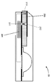
도 1은 몇몇 실시예에 따른, 유체 유동을 계량하기 위한 수동 밸브를 구비한 비제한적인 예시적인 미세 유체 장치의 단면도를 도시하고;
도 2는 몇몇 실시예에 따른, 유체 유동을 계량하기 위한 능동 밸브를 구비한 비제한적인 예시적인 미세 유체 장치의 단면도를 도시하며;
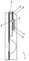
도 3a는 몇몇 실시예에 따른, 유체 유동을 지연시키기 위해 표면 에너지의 상호 작용을 이용하는 관심 대상인 하나 이상의 분석물과 몰삼투압 농도의 통합 검출을 위한 비제한적인 예시적인 미세 유체 장치의 단면도를 도시하고;
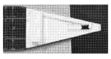
도 3b 및 도 3c는 몇몇 실시예에 따른, 표면 에너지 기반 유동 지연 메카니즘을 구현하는 미세 유체 장치를 사용하여 얻어진 비제한적인 예시적인 유동 결과를 도시하며;
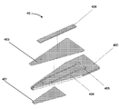
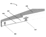
도 4a는 몇몇 실시예에 따른, 수동 밸브를 구비한, 하나 이상의 분석물의 검출과 몰삼투압 농도의 통합 검출을 위한 비제한적인 예시적인 미세 유체 장치의 분해도를 도시하고;
도 4b는 도 4a의 조립된 미세 유체 장치의 단면도를 도시하며;
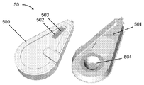
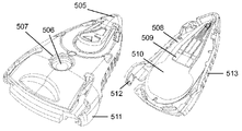
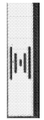
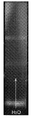
도 5a 및 도 5b는 몇몇 실시예에 따른, 몰삼투압 농도와 관심 대상인 하나 이상의 분석물의 통합 검출을 위한 비제한적인 예시적인 조립된 미세 유체 장치의 평면도 및 저면도를 도시하고;
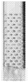
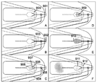
도 6a 내지 도 6g는 몇몇 실시예에 따른, 유동 균질화를 달성하기 위한 기하학적 형태를 갖는 비제한적인 예시적인 검출 기재를 도시하며;
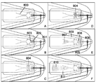
도 7은 몇몇 실시예에 따른, 정밀 유체 타이밍 지연을 수행하도록 구성된 비제한적인 예시적인 검출 기재를 도시하고;
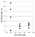
도 8은 약 100 nL의 인간 눈물 유체를 사용하여 연속적으로 측정된 몰삼투압 농도와 250 ng/mL IgE의 비제한적인 예시를 도시하며;
도 9는 분리된 재수화 채널을 포함하는 재수화 구조 내의 멀티플렉스 분석의 비제한적인 예시를 도시한다.The novel features of the invention are set forth in detail in the appended claims. BRIEF DESCRIPTION OF THE DRAWINGS A better understanding of the features and advantages of the present invention will be obtained by reference to the following detailed description and the accompanying drawings, which illustrate exemplary embodiments in which the principles of the invention are employed. In the accompanying drawings:
1 illustrates a cross-sectional view of a non-limiting exemplary microfluidic device with a manual valve for metering fluid flow, according to some embodiments;
Figure 2 shows a cross-sectional view of a non-limiting exemplary microfluidic device with an active valve for metering fluid flow, according to some embodiments;
3A shows a cross-sectional view of an exemplary non-limiting microfluidic device for integrated detection of molar osmolarity concentration with one or more analytes of interest utilizing interactions of surface energy to retard fluid flow, according to some embodiments ;
Figures 3B and 3C illustrate non-limiting exemplary flow results obtained using a microfluidic device implementing a surface energy based flow delay mechanism, in accordance with some embodiments;
4A illustrates an exploded view of a non-limiting exemplary microfluidic device for the detection of one or more analytes and the combined detection of molar osmolarity concentrations, with a manual valve, according to some embodiments;
Figure 4b shows a cross-sectional view of the assembled microfluidic device of Figure 4a;
Figures 5A and 5B illustrate top and bottom views of a non-limiting exemplary assembled microfluidic device for integrated detection of a molar osmolarity concentration and one or more analytes of interest, in accordance with some embodiments;
Figures 6A-6G illustrate a non-limiting exemplary detection substrate having a geometric shape for achieving flow homogenization, in accordance with some embodiments;
Figure 7 illustrates a non-limiting exemplary detection substrate configured to perform precision fluid timing delays, in accordance with some embodiments;
Figure 8 shows a non-limiting example of a continuously measured molar osmolarity concentration and 250 ng / mL IgE using about 100 nL of human tear fluid;
Figure 9 shows a non-limiting example of a multiplex analysis in a rehydration structure comprising a separate rehydration channel.
본 개시는, 특정 실시예에서, 소량(비제한적인 예로서, 약 20 마이크로리터 미만)의 유체 샘플을 포집 및 분석하기 위한 시스템, 방법, 및 장치를 제공한다. 본 명세서에 개시되는 시스템, 방법 및 장치는, 몇몇 실시예에서, 관심 대상인 유체 샘플의 하나 이상의 피쳐를 검출 및/또는 측정하는 데에 사용된다. 비제한적인 예로서, 시스템, 방법 및 장치는 제1 피쳐(비제한적인 예로서, 관심 대상인 유체의 삼투질 농도(osmolality)) 및 관심 대상인 제2 피쳐(비제한적인 예로서, 관심 대상인 유체 내의 하나 이상의 분석물의 존재 및/또는 농도)를 측정하는 데에 사용된다. 몇몇 실시예에서, 시스템, 방법 및 장치는 관심 대상인 유체 내의 하나 이상의 분석물의 존재 및/또는 농도를 측정하는 데에 사용된다. 몇몇 실시예에서, 시스템, 방법 및 장치는 제1 피쳐(비제한적인 예로서, 관심 대상인 유체의 삼투질 농도) 또는 관심 대상인 제2 피쳐(비제한적인 예로서, 관심 대상인 유체 내의 하나 이상의 분석물의 존재 및/또는 농도)를 측정하는 데에 사용된다.The present disclosure, in a particular embodiment, provides a system, method, and apparatus for capturing and analyzing small (non-limiting example, less than about 20 microns) fluid samples. The systems, methods, and apparatus described herein are used in some embodiments to detect and / or measure one or more features of a fluid sample of interest. By way of non-limiting example, the system, method, and apparatus may include a first feature (osmolality of the fluid of interest as a non-limiting example) and a second feature of interest (such as, The presence and / or concentration of one or more analytes). In some embodiments, a system, method, and apparatus are used to measure the presence and / or concentration of one or more analytes in a fluid of interest. In some embodiments, the system, method, and apparatus may include a first feature (osmotic concentration of the fluid of interest as a non-limiting example) or a second feature of interest (such as, but not limited to, Presence < / RTI > and / or concentration).
본 발명은 현장에서의 사용을 위해 통합된 장치에서 유체의 나노리터(nL) 샘플을 포집 및 분석하려고 할 때에 발생할 수 있는 문제들을 처리한다. 소량의 샘플은 동일한 농도에서 더 큰 부피보다 검출할 분자가 적고 매우 높은 민감도를 필요로 한다. 일반적으로, 분석은 비특이적인 배경을 제거하기 위해 반복적이고 엄격한 세정이 동반되는 검출기 표면에서 확산이 관심 대상인 분석물을 축적하는 데에 일조하게 하도록 1시간 넘게 하룻밤 이상까지 긴 배양 시간에 의해 이 문제를 해결하려고 한다. 이러한 기술 중 어느 것도 현장에서 이용 가능하지 않으며, 이는 완전히 훈련되지 않은 유저에 의해 작동 가능한 간단한 시스템에 의해 신속한 테스트(비제한적인 예로서, 몇 분 미만)를 필요로 한다. 또한, 임피던스 기반의 눈물 몰삼투압 농도와 크로마토그래피 유형(또는 측방 유동)의 샌드위치 분석을 연속적으로 분석할 때에, 다음과 같은 다양한 문제들 중 임의의 문제가 발생할 수 있다: 포집된 유체를 정확하게 계량하는 것, 검출 항체의 재수화(또는 비제한적인 예로서, 나노 입자 복합체, 앱타머(aptamer), scFv 등을 포함함), 샘플 전달 효율, 눈물 샘플이 샘플 영역을 완전히 통과하기 전에 포획 항체의 재수화를 달성하는 것, 미 공성 측방 유동 멤브레인 위에서 흐르는 완충제의 오버플로우를 방지하는 것, 균질화 유동(검출 항체의 선단 에지에서 실질적으로 등방성이며 균일한 유동 패턴을 생성하는 것, 또는 이와 달리, 반응된 눈물 샘플과 검출 복합체 앞쪽의 대부분이 그 주위가 아니라 포획 영역을 통해 유동함), 그리고 유동을 크로마토그래피 시스템의 한쪽 또는 다른 쪽으로 무작위로 이동시키는 유동 불안정성을 피하는 것. The present invention addresses problems that may arise when attempting to capture and analyze nanoliter (nL) samples of fluid in an integrated device for field use. A small amount of sample requires fewer molecules to detect than a larger volume at the same concentration and requires very high sensitivity. In general, the analysis is carried out by a long incubation time of one hour or more over a period of one hour to allow the diffusion to accumulate the analyte of interest at the detector surface, accompanied by repetitive and stringent rinsing, to remove the nonspecific background. I want to solve it. Neither of these techniques is available in the field, which requires rapid testing (less than a few minutes as a non-limiting example) by a simple system that can be operated by a completely untrained user. In addition, when continuously analyzing sandwich analysis of impedance-based tear molar osmolarity and chromatographic type (or lateral flow), any of a variety of problems can occur, including: (Including, but not limited to, nanoparticle complexes, aptamers, scFv, and the like), sample delivery efficiency, the ability of the capture antibody to pass through the sample area To prevent overflow of the buffering agent flowing over the microporous lateral flow membrane, to produce a substantially isotropic and uniform flow pattern at the leading edge of the detection antibody, or alternatively, Most of the anterior tear samples and detection complexes flow through the capture region, not its periphery), and the flow is chromatographed Avoiding flow instabilities that randomly move to one or the other side of the system.
이들 문제를 해결하기 위해, 본 개시는, 몇몇 실시예에서, (a)샘플 유체의 부분 표본 부피를 수용하는 기재로서, 기재는 모세관 작용을 통해 샘플 유체의 부분 표본 부피를 수용하도록 작동 가능하게 형성되는 것인 기재; 및 (b)샘플 유체의 부피가 샘플 영역의 일부를 작동 가능하게 덮기에 충분한 크기로 되어, 샘플 유체의 에너지 특성이 샘플의 몰삼투압 농도를 나타내는 샘플 유체 판독값을 생성하도록 변환되게 하는, 상기 기재의 샘플 유체 영역, 및(c) 관심 대상인 분석물에 대해 샘플 유체의 일부를 분석하는 제2 샘플 영역 중 적어도 하나를 포함하는 일체형 미세 유체 포집 장치를 제공한다. 특정 실시예에서, 본 명세서에 개시된 장치 및 시스템은 또한 샘플 유체를 계량하기 위한 일련의 하나 이상의 평형 수동 밸브를 포함하며, 시스템을 통과하는 가압 유체는 미리 결정된 순서로 밸브를 횡단하게 된다. 특정 실시예에서, 본 명세서에 개시된 장치 및 시스템은 또한 적어도 하나의 일체형 저장조를 포함한다. 몇몇 실시예에서, 저장조는 그 내부에 완충제, 세정액, 전달 유체, 샘플 유체, 기체, 공기 또는 임의의 다른 유체 부피를 보유한다. 몇몇 실시예에서, 저장조는 그 내부에 전달 완충제, 세정액, 전달 유체, 샘플 유체, 기체, 공기 또는 임의의 다른 유체 부피 중 2개 이상을 보유하도록 분할된다. 몇몇 실시예는 샘플 전달 효율, 재수화 역학, 오버플로우 보호 및 유동 불안정성을 피하기 위한 유체 저항 평형을 최적화하도록 작동 가능하게 형성되는, 미세 다공성 기재를 포함하는 제2 샘플 영역을 특징으로 한다. 특정 실시예에서, 샘플 전달 효율은 미세 다공성 기재의 작은 돌출부를 2 개의 샘플 영역들 사이의 계면에 배치함으로써 최적화된다. 다른 실시예에서, 검출 복합체의 재수화 역학은 면역 분석의 검출 복합체를 수동 밸브의 계량된 쪽, 또는 포집 채널 내측, 또는 양쪽 모두에 위치시킴으로써 달성된다. 다른 실시예에서, 검출 복합체의 재수화는 샘플 전달 후에 미세 다공성 기재 내에서 달성된다. 다른 실시예에서, 포획 영역의 재수화 역학은 최소 저항의 유체 경로가 그 주위가 아닌 포획 영역을 통과하도록 하류 유체 협착부를 위치시킴으로써 달성된다. 다른 실시예에서, 포획 영역의 재수화는 유체 단면 경로의 신속한 팽창의 하류에서 달성된다. 또 다른 실시예에서, 포획 영역의 재수화는 유체 지연 및 샘플 전달을 위한 우선 경로로서 작용하는 하나 이상의 사형 채널을 미세 다공성 기재 내에 패터닝함으로써 달성되며, 보다 짧은 경로 길이의 재수화 채널은 지연된 샘플이 도달하기 전에 하류 포획 영역으로 전달 완충제를 위킹하며, 이 지점에서 재수화 및 샘플 경로가 병합된다. 다른 실시예에서, 중앙 샘플 경로를 둘러싸는 보다 짧은 경로 길이의 재수화 채널은 재수화 채널 및 샘플 채널이 단일 경로로 병합된 후에 검출기의 생성된 유동을 보다 예측 가능한 영역으로 집중시킨다. 다른 실시예에서, 저장조로부터의 압력 구동 오버플로우(pressure driven overflow)의 가능성을 완화하는 데에 일조하도록 하나 이상의 유체 채널이 추가된다. 다른 실시예에서, 재수화 및 오버플로우 보호 채널은 하나의 구조로 결합된다. 추가적인 실시예에서, 하류의 샘플 유동 저항기들은, 시스템 내에서 유동 불안정성 및 예측 불가능성을 야기하는 미세 다공성 기재를 통과하는 비대칭 경로를 유동이 무작위로 선택하는 것을 방지하도록 밸런싱된다. 다른 실시예에서, 비대칭 유동 불안정성이 시스템에서 허용되고 대칭 경로의 양측에 여분의 포획 영역을 위치시킴으로써 보상되며 그 강도는 소프트웨어에서 평균이 된다. 총괄하여, 이들 피쳐는 나노리터 크기의 샘플에서 관심 대상인 하나 이상의 분석물의 병렬 분석 문제를 해결한다.To solve these problems, the present disclosure provides, in some embodiments, (a) a substrate for receiving a sample volume of a sample fluid, wherein the substrate is operatively formed to receive a sample volume of the sample fluid through capillary action Lt; / RTI > And (b) causing the volume of the sample fluid to be of a size sufficient to operatively cover a portion of the sample region such that the energy characteristic of the sample fluid is converted to produce a sample fluid reading indicative of a molar osmotic concentration of the sample. And (c) a second sample region for analyzing a portion of the sample fluid relative to the analyte of interest. In certain embodiments, the apparatus and system described herein also include a series of one or more balanced manual valves for metering the sample fluid, wherein the pressurized fluid passing through the system traverses the valve in a predetermined order. In certain embodiments, the apparatus and system described herein also include at least one integral reservoir. In some embodiments, the reservoir holds a buffer, a rinse solution, a transfer fluid, a sample fluid, a gas, an air, or any other fluid volume therein. In some embodiments, the reservoir is divided to retain two or more of the transfer buffer, the rinse fluid, the transfer fluid, the sample fluid, the gas, the air, or any other fluid volume therein. Some embodiments feature a second sample region comprising a microporous substrate that is operatively formed to optimize fluid resistance equilibrium to avoid sample transfer efficiency, rehydration dynamics, overflow protection, and flow instability. In certain embodiments, the sample transfer efficiency is optimized by placing small protrusions of the microporous substrate at the interface between the two sample regions. In another embodiment, the rehydration epidemiology of the detection complex is achieved by placing the detection complex of immunoassay on the metered side of the manual valve, or inside the collection channel, or both. In another embodiment, rehydration of the detection complex is achieved in a microporous substrate after sample delivery. In another embodiment, the rehydration dynamics of the capture region is achieved by locating the downstream fluid constriction so that the minimal resistance fluid path passes through the capture region, not around it. In another embodiment, re-hydration of the capture zone is achieved downstream of rapid expansion of the fluid cross-section path. In another embodiment, re-hydration of the capture region is achieved by patterning one or more sandwich channels in the microporous substrate that act as a preferred path for fluid delay and sample transfer, Before reaching, the transfer buffer is wicked into the downstream capture region, at which point the rehydration and sample paths are merged. In another embodiment, a rework channel with a shorter path length surrounding the central sample path concentrates the generated flow of the detector into a more predictable region after the rehydration channel and sample channel are merged into a single path. In another embodiment, one or more fluid channels are added to aid in mitigating the possibility of pressure driven overflow from the reservoir. In another embodiment, the rehydration and overflow protection channels are combined into one structure. In a further embodiment, the downstream sample flow resistors are balanced to prevent the flow from randomly selecting an asymmetric path through the microporous substrate that causes flow instability and unpredictability in the system. In another embodiment, asymmetric flow instability is tolerated in the system and compensated by placing an extra trapping region on either side of the symmetry path, the intensity of which is averaged in software. Collectively, these features solve the problem of parallel analysis of one or more analytes of interest in nanoliter sized samples.
몇몇 실시예에서, 관심 대상인 유체 샘플의 부피는 단일의 미세 유체 장치 내의 복수 개의 샘플 영역을 통해 순차적으로 그리고 제어 가능하게 유동된다. 몇몇 실시예에서, 각각의 샘플 영역은 삼투압, 총 농도, 삼투질 농도 및/또는 몰삼투압 농도와 같은 샘플 부피의 다양한 특성을 분석하고 검출하기 위한, 뿐만 아니라 관심 대상인 하나 이상의 분석물의 검출을 위한 다양한 검출 구성요소를 포함한다. 본 개시의 몇몇 실시예는 환자에게 상해의 위험을 최소화하면서 비교적 빠르며, 비침습적이고, 저렴하며, 및/또는 사용하기 쉽도록 구성된다. 몇몇 실시예에서, 최소한 마이크로리터 부피의 샘플 유체에 정확한 측정이 제공된다. 비제한적인 예로서, 본 명세서에 설명된 몇몇 실시예에 따라 구성된 측정 장치는 20 마이크로리터 이하의 샘플 유체에 몰삼투압 농도 측정을 가능하게 한다. 몇몇 실시예에서, 비제한적인 예로서, 보다 작은 부피, 때로는 20 나노리터만큼 작은 나노리터 부피가 성공적으로 측정된다. 몇몇 실시예에서, 측정 성능은 포집된 샘플 유체의 부피의 변화에 의해 손상되지 않으므로, 몰삼투압 농도 및 관심 대상인 하나 이상의 분석물의 측정은 포집된 부피와 실질적으로 무관하다. 일 실시예에서, 이는 샘플 유체의 부분 표본 부피의 널리 정의된 하위 세트를 조사함으로써 달성된다. 몇몇 실시예에서, 본 명세서에 설명된 방안은 단일의 통합 장치 내에서 작은 샘플 부피의 신속한 분석을 가능하게 함으로써, 유체 샘플의 진단 테스트의 속도, 융통성, 사용자 편리성, 및 비용 효율성을 향상시킨다. In some embodiments, the volume of a fluid sample of interest flows sequentially and controllably through a plurality of sample regions in a single microfluidic device. In some embodiments, each of the sample regions is adapted for analyzing and detecting various characteristics of the sample volume, such as osmotic pressure, total concentration, osmotic concentration and / or molar osmotic concentration, as well as a variety of analytes for the detection of one or more analytes of interest Detection component. Some embodiments of the present disclosure are configured to be relatively fast, non-invasive, inexpensive, and / or easy to use, while minimizing the risk of injury to the patient. In some embodiments, an accurate measurement is provided for at least a microliter volume of sample fluid. By way of non-limiting example, a measuring device configured in accordance with some embodiments described herein enables the measurement of molar osmolarity concentration in a sample fluid of 20 microliters or less. In some embodiments, as a non-limiting example, smaller volumes, sometimes as small as 20 nanoliters, are successfully measured. In some embodiments, the measurement performance is not compromised by changes in the volume of the captured sample fluid, so that the measurement of the molar osmolarity concentration and of the one or more analytes of interest is substantially independent of the collected volume. In one embodiment, this is accomplished by examining a widely defined subset of the sample volume of the sample fluid. In some embodiments, the approaches described herein enable rapid analysis of small sample volumes within a single integrated device, thereby improving the speed, flexibility, user friendliness, and cost effectiveness of diagnostic testing of fluid samples.
몇몇 실시예에서, 본 명세서에 설명된 장치는 눈물막, 땀, 혈액, 소변, 침, 또는 다른 체액, 또는 이들의 조합을 비롯하여 다양한 상이한 유형의 유체를 분석하는 데에 사용된다. 몇몇 실시예에서, 본 명세서에 설명된 장치는 우유 또는 다른 음료 뿐만 아니라 다양한 완충제, 용액, 시약, 또는 화학 물질, 또는 이들의 조합과 같은 다른 샘플 유체를 분석하는 데에 사용된다. In some embodiments, the devices described herein are used to analyze a variety of different types of fluids, including tear films, sweat, blood, urine, saliva, or other body fluids, or combinations thereof. In some embodiments, the devices described herein are used to analyze other sample fluids such as milk or other beverages as well as various buffers, solutions, reagents, or chemicals, or combinations thereof.
몇몇 실시예에서, 본 명세서에 설명된 장치는 환자로부터의 눈물 유체를 분석하는 데에 사용된다. 몇몇 실시예에서, 눈물 유체 분석은 환자의 눈물막에 이상이 나타나는 다양한 눈 상태의 진단, 모니터링 및/또는 치료에 유익하다. 예컨대, 건성 각결막염(KCS; Keratoconjunctivitis sicca), 또는 "안구 건조증(dry eye)"은 눈물막 구조 성분들(비제한적인 예로서, 하부의 뮤신 기부, 중간의 수성 성분, 상부의 지질층) 중 하나 이상이 불충분한 부피로 존재하거나 이와 달리 다른 성분들과의 균형이 맞지 않는 상태이다. KCS가 있는 환자에서 눈물의 유체 긴장성 또는 몰삼투압 농도가 증가된다는 점이 알려져 있다. KCS는 쇼그렌 증후군, 노화, 및 안드로겐 결핍과 같은 신체의 전반적인 건강에 영향을 미치는 조건과 관련이 있다. 따라서, 눈물막의 몰삼투압 농도는 KCS 및 다른 상태의 진단을 위한 민감하고 구체적인 지표이다.In some embodiments, the device described herein is used to analyze tear fluid from a patient. In some embodiments, tear fluid analysis is beneficial for the diagnosis, monitoring and / or treatment of various eye conditions in which an abnormality is present in the patient's tear film. For example, dry keratoconjunctivitis sicca (KCS), or "dry eye", is one of the tear film structural components (non-limiting example, lower mucinous base, middle aqueous component, upper lipid layer) Is present in an insufficient volume or otherwise unbalanced with other components. It is known that fluid tensions or molar osmotic concentrations of tears increase in patients with KCS. KCS is associated with conditions that affect the overall health of the body, such as Sjogren's syndrome, aging, and androgen deficiency. Thus, the molar osmotic concentration of the tear film is a sensitive and specific indicator for the diagnosis of KCS and other conditions.
또한, 최근의 증거에 따르면, 눈물의 고 몰삼투압 농도(hyperosmolarity)는 눈물막의 불안정성, 즉 눈물막이 혈액 몰삼투 농도와 평형을 이루는 항상성계(homeostatic system)로부터 점진적으로 더 혼란하고 예측 불가능한 구조의 형태로 전이되는 상태와 직접적으로 연계되어 있다는 점이 밝혀졌다. 안구 건조증의 초기 단계에서, 눈물막은 준안정적일 수 있고, 이 경우, 깜박임간 강도 변화, 눈꺼풀 접촉 등이 전술한 변수에 따라 가변적으로 유능한 박막을 끌어낸다. 진행된 안구 건조증, 또는 불안정성을 조장하는 임의의 다른 안구 표면 상태에서, 눈물막은 응집력이 막의 어떠한 외관을 유지하기에 불충분하고 각막과 결막 위에서 신속한 증발이 생기는 단계까지 손상된다. 그러한 불안정성은 눈물막 샘플 내의 단백질 바이오마커와 같은 분석물을 측정하려고 할 때에 관련 있다. 예컨대, 눈물 바이오마커의 포인트 샘플(비제한적인 예로서, 단일의 샘플 포집 시점에서 바이오마커의 농도에 데이터를 제공하는 체외 진단 단일 사용 일회용 테스트를 위한)은, 눈물의 불안정성으로 인한 농도의 1차 변화와 증발성 수분 손실로 인한 결과적인 고 몰삼투압 농도 때문에 샘플 몰삼투압 농도가 해명되지 않는다면 임상적 결정을 내릴 때에 받아들일 수 없는 변화가 생기기 쉽다. In addition, recent evidence suggests that hyperammoniosity of tears may lead to instability of the tear film, a gradual more confusing and unpredictable form of structure from the homeostatic system where the tear film equilibrates with the blood molar osmotic concentration And that it is directly related to the state of transition. In the early stages of dry eye syndrome, the tear film may be metastable, in which case flicker intensity changes, eyelid contact, and the like elicit variable thin films depending on the aforementioned variables. In advanced ocular dryness, or any other ocular surface condition that promotes instability, the tear film is impaired to the point where cohesion is insufficient to maintain any appearance of the membrane and rapid evaporation occurs on the cornea and conjunctiva. Such instability is relevant when trying to measure an analyte such as a protein biomarker in a tear film sample. For example, a point sample of a tear biomarker (for non-limiting example, an in vitro diagnostic single use disposable test that provides data on the concentration of a biomarker at a single sample collection time point) If the sample molar osmotic concentration is not accounted for because of the resulting high molar osmotic concentration due to change and evaporative water loss, then unacceptable changes are likely to occur when making clinical decisions.
몇몇 실시예에서, 관심 대상인 복수 개의 분석물이 분석되어 하나 이상의 안질환의 진단 및 관리를 돕는 데에 사용된다. 안질환의 비제한적인 예는, 연령 관련 황반 변성, 알러지, 안검염(blepharitis), 백내장(cataract), 결막염(conjunctivitis), 봉와직염(cellulitis), 중심 장액 망막 병증(central serous retinopathy), 콩다래끼(chalazion), 콘택트 렌즈 관련 손상, 각막/결막 찰과상, 이영양증(dystrophies), 짓무름(erosion), 열상(laceration), 궤양(ulcer), 각막 이식 거부(corneal transplant rejection), 거대세포바이러스 망막염(cytomegalovirus retinitis), 당뇨병성 망막증(diabetic retinopathy), 안암(eye cancer), 푸크스 이영양증(Fuch's dystrophy), 그레이브스병(Grave's disease), 히스토플라스마증(histoplasmosis), 녹내장(glaucoma), 감염(infection), 각막염(keratitis), 원추 각막(keratoconus), 황반 질환(macular disease), 신생 혈관증(neovascularization), 고안압증(ocular hypertension), 시신경염(optic neuritis), 검열반(pinguecula), 익상편(pterygium), 망막 세포 변성증(retinitis pigmentosa), 망막 모세포종(retinoblastoma), 공막염(scleritis), 트라코마(trachoma), 첩모난생증(trichiasis), 및 포도막염(uveitis)을 포함한다. 몇몇 실시예에서, 특정 분석물(및/또는 몰삼투압 농도와 같은 유체 특성)의 평행 해석(비제한적인 예로서, 복수 개의 분석물 중 임의의 분석물이 긍정적이면, 긍정적인 진단을 내리는 논리 OR)이 사용되어 많은 특이성을 희생시키지 않으면서 안질환 테스트 전반적인 민감도를 증가시킨다. 비제한적인 예로서, 일 실시예에서, 몰삼투압 농도, 락토페린, 알부민, 및 리포칼린의 평행 해석이 안구 건조증 질환을 진단하는 데에 사용된다. 다른 실시예에서, 몰삼투압 농도, 리포칼린, 프롤린-농후 단백질 4(PRR4) 및 아연-알파-2-글리코프로테인 2(ZAG2)(또는 다른 주요 눈물 단백질)의 평행 해석이 단백질 레벨이 정상 범위보다 낮을 때에 안구 건조증 질환을 진단하는 데에 사용된다. 또 다른 실시예에서, 몰삼투압 농도, 리포칼린, PRR4 및 ZAG2(또는 다른 주요 눈물 단백질)의 평행 해석이 단백질 레벨이 정상 범위보다 높을 때에 생무지의 미치료 녹내장(naive untreated glaucoma)을 진단하는 데에 사용된다. 또 다른 실시예에서, 몰삼투압 농도, 리포칼린, PRR4 및 ZAG2(또는 다른 주요 눈물 단백질)의 평행 해석이 동일한 장치에서 안구 건조증과 녹내장을 모두 진단하는 데에 사용된다. 몇몇 실시예에서, 몰삼투압 농도 및 당화 알부민(glycated albumin)의 평행 해석은, 측정된 몰삼투압 농도에 대해 당화 알부민 농도를 정규화함으로써 눈물 농도의 깜박임 간 변화를 보상하여, 건강한 환자, 당뇨병 환자, 및 망막증을 가진 당뇨병 환자 간의 구별에 있어서 정밀도를 증가시킬 수 있게 한다. 또 다른 실시예에서, 몰삼투압 농도와 뇌유래 신경 영양 인자(BDNF; brain-derived neurotrophic factor)의 평행 해석은 측정된 눈물 몰삼투압 농도에 대해 BDNF 레벨을 정규화함으로써 저안압 녹내장(low tension glaucoma)의 결정에 개선된 정밀도를 허용한다. 다른 실시예에서, 몰삼투압 농도, IL-1Ra, MMP-9 및 S100A8의 평행 해석은 염증성 또는 수분 결핍 여부에 상관없이 안구 건조증 질환 및 장애의 원인 하위 세트 모두를 진단하는 데에 일조한다. 다른 실시예예에서, 중첩되는 증상 및 임상 징후를 갖는 상이한 질환으로부터의 관심 대상인 다수의 분석물이 병행하여 측정된다. 비제한적인 예로서, 일 실시예에서, 유사한 임상 증상 및 징후에도 불구하고 안구 건조증과 알러지를 구별하면서 조기 및 후기 알러지 모두를 조사하기 위해 몰삼투압 농도 뿐만 아니라 IgE, ECP 및/또는 EDN과 같은 복수 개의 알러지 마커가 측정된다. 다른 실시예에서, 몰삼투압 농도는 측정되지 않고, 관심 대상인 분석물이 측정된다. 이들 예는 제한되도록 의도되지 않고, 개시된 장치를 현장에서 어떻게 적용하는지에 관한 예를 제공한다.In some embodiments, a plurality of analytes of interest are analyzed and used to aid in the diagnosis and management of one or more eye diseases. Non-limiting examples of ocular disease include age related macular degeneration, allergies, blepharitis, cataract, conjunctivitis, cellulitis, central serous retinopathy, chalazion ), Contact lens related injuries, corneal / conjunctival abrasions, dystrophies, erosion, laceration, ulcer, corneal transplant rejection, cytomegalovirus retinitis, Diabetic retinopathy, eye cancer, Fuch's dystrophy, Grave's disease, histoplasmosis, glaucoma, infection, keratitis, Keratoconus, macular disease, neovascularization, ocular hypertension, optic neuritis, pinguecula, pterygium, retinitis (retinitis), retinitis pigmentosa, retinitis pigmentosa, s pigmentosa, retinoblastoma, scleritis, trachoma, trichiasis, and uveitis. In some embodiments, a parallel analysis of a particular analyte (and / or a fluid property such as molar osmolarity concentration), such as, but not limited to, a logical OR of a positive diagnosis if any of the plurality of analytes is positive ) Is used to increase the overall sensitivity of the eye disease test without sacrificing many specificities. By way of non-limiting example, in one embodiment, parallel analysis of molar osmolarity concentrations, lactoferrin, albumin, and lipocalin is used to diagnose dry eye disease. In another embodiment, a parallel analysis of molar osmolarity levels, lipocalin, proline-rich protein 4 (PRR4) and zinc-alpha-2-glycoprotein 2 (or other major tear protein) It is used to diagnose dry eye syndrome at low temperature. In another embodiment, parallel analysis of molar osmolarity levels, lipocalin, PRR4, and ZAG2 (or other major tear protein) is used to diagnose naive untreated glaucoma in the vagina when the protein level is above the normal range Is used. In another embodiment, parallel analysis of molar osmolarity levels, lipocalin, PRR4 and ZAG2 (or other major tear protein) is used to diagnose both dry eye syndrome and glaucoma in the same device. In some embodiments, the parallel analysis of molar osmolarity and glycated albumin compensates for a change in flickering of tear concentration by normalizing the glycosylated albumin concentration relative to the measured molar osmolarity concentration, To increase precision in the distinction between diabetic patients with retinopathy. In another embodiment, a parallel analysis of the molar osmolarity and brain-derived neurotrophic factor (BDNF) is performed by normalizing the BDNF level against the measured tearmolar osmolarity concentration to determine the effect of low tension glaucoma Allows improved precision in crystals. In another embodiment, parallel analysis of molar osmolarity concentrations, IL-1Ra, MMP-9 and S100A8 helps diagnose both the underlying subset of dry eye diseases and disorders, irrespective of inflammation or moisture deficiency. In another embodiment, multiple analytes of interest from different diseases with overlapping symptoms and clinical signs are measured in parallel. By way of non-limiting example, in one embodiment, in order to investigate both early and late allergy while distinguishing allergies from dry eye syndromes despite similar clinical symptoms and signs, Allergic markers are measured. In another embodiment, the molar osmotic concentration is not measured and the analyte of interest is measured. These examples are not intended to be limiting and provide examples of how to apply the disclosed apparatus in the field.
따라서, 본 개시는 몇몇 실시예에서, 일정 부피 내에 관심 대상인 하나 이상의 분석물(비제한적인 예로서, 하나 이상의 분석물의 존재 및/또는 농도)을 측정하는 것과 함께 (비제한적인 예로서, 눈물막 또는 다른 유체 샘플의) 부분 표본 부피의 몰삼투압 농도를 측정하는 시스템, 방법, 및 장치를 제공한다. 몇몇 실시예에서, 몰삼투압 농도와 분석물 측정은 동시에 또는 순차적으로 수행된다. 몇몇 실시예에서, 몰삼투압 농도 측정이 먼저 수행되고, 이후에 샘플 부피 내에서 하나 이상의 분석물의 존재 및/또는 농도를 검출하기 위한 분석이 수행된다. 몇몇 실시예에서, 몰삼투압 농도 측정은, 샘플 부피 내에서 하나 이상의 분석물의 존재 및/또는 농도를 검출하기 위한 분석 다음에 수행된다. 다른 실시예에서, 샘플의 몰삼투압 농도는 비교적 일정하며 관심 대상인 분석물만이 분석된다. Thus, the present disclosure is directed, in some embodiments, to a method of measuring the presence (or concentration) of one or more analytes of interest (such as, without limitation, the presence and / or concentration of one or more analytes, Method and apparatus for measuring the molar osmotic concentration of a sample volume of a sample (e.g., of a sample, or of a different fluid sample). In some embodiments, the molar osmolarity concentration and analyte measurement are performed simultaneously or sequentially. In some embodiments, the molar osmolarity concentration measurement is performed first, followed by analysis to detect the presence and / or concentration of one or more analytes within the sample volume. In some embodiments, the molar osmolarity concentration measurement is performed after the analysis to detect the presence and / or concentration of one or more analytes in the sample volume. In another embodiment, the molar osmotic concentration of the sample is relatively constant and only the analyte of interest is analyzed.
몇몇 실시예에서, 임의의 적절한 기법이 유체 샘플의 몰삼투압 농도를 측정하는 데에 사용된다. 몇몇 실시예에서, 몰삼투압 농도는, 샘플의 에너지 특성(비제한적인 예로서, 열적, 광학적, 및/또는 전기적 특성)을 검출함으로써, 예컨대 에너지를 샘플에 전달하고, 인가된 에너지를 검출하며, 검출 결과를 몰삼투압 농도를 결정하는 데에 이용함으로써, 측정된다. 몇몇 실시예에서, 하나 이상의 트랜스듀서 또는 전극이 적절한 전기 신호를 인가함으로써 비제한적인 예로서 유체의 전기 전도도를 측정하는 데에 사용된다. 전기 전도도는 유체의 이온 농도와 관련되어 있으므로, 온도 보정 및 적절한 교정 기능이 적용되면 유체의 몰삼투압 농도가 결정될 수 있다.In some embodiments, any suitable technique is used to measure the molar osmotic concentration of the fluid sample. In some embodiments, the molar osmolarity concentration can be determined by detecting the energy characteristics of the sample (such as, but not limited to, thermal, optical, and / or electrical characteristics) And using the detection result to determine the molar osmotic concentration. In some embodiments, one or more transducers or electrodes are used to measure the electrical conductivity of the fluid as a non-limiting example by applying an appropriate electrical signal. Since electrical conductivity is related to the ionic concentration of the fluid, the molar osmolarity of the fluid can be determined by temperature compensation and appropriate calibration.
본 명세서에서 제시된 기술, 시스템 및 장치를 사용하여 유체 샘플에서 측정될 수 있는 분석물은, 제한하지 않지만, 다른 생물학적 성분과 고차 어셈블리 중에서도 단백질, 펩타이드, 대사 산물, 전해질, 소분자, 지질, 당, 핵산 및 프로테오글리칸을 뿐만 아니라 이들의 조합을 포함한다. 몇몇 실시예에서, 분석물은 단백질 바이오마커를 포함한다. 몇몇 실시예에서, 분석물은, 제한하지 않지만, 면역글로불린[비제한적인 예로서, 면역글로불린 E(IgE), 면역글로불린 M(IgM), 면역글로블린 A(IgA), 면역글로불린 G(IgG)], 사이토카인[비제한적인 예로서, 변환 성장 인자-β(TGF-β), 종양 괴사 인자(TNF-α), 인터루킨 1-A], 단백질[S100, 락토페린, 리포칼린, 카텝신, BDNF, 엔올라제, 호산구 양이온 단백질(ECP; Eosinophil Cationic Protein), 호산구 유래 신경독소(EDN; Eosinophil Derived Neurotoxin), PRR4, ZAG2, 시스스타틴(cystatin), 알부민 등] 또는 뮤신 및 기타 당단백질[비제한적인 예로서, 세포 표면 관련 뮤신 5(MUC-5), 프로테오글리칸 4(PRG4), 세포 표면 관련 뮤신 16(MUC16)]을 포함한다. 몇몇 실시예에서, 분석물 검출 및/또는 측정 절차는 검출 기재를 통해 유체 샘플을 유동시키는 것을 포함한다. 비제한적이고 예시적인 검출 기재는 미세 다공성 기재 또는 미세 다공성 멤브레인을 포함한다. 추가의 실시예에서, 검출 기재는 니트로셀룰로오스, 유리 섬유 복합 패드, 퓨전 5(Fusion 5), POREX® 물질, 종이, PVDF 등으로부터 선택되는 하나 이상의 기재이다. 몇몇 실시예에서, 미세 다공성 기재 및 미세 다공성 멤브레인은 동등하며, 본 명세서 내에서 상호 교환 가능하다. 몇몇 실시예에서, 포집 채널, 모세관 채널, 및 미세 유체 채널은 동등한 용어이며, 본 명세서 내에서 상호 교환 가능하다. 몇몇 실시예에서, 검출 기재는 관심 대상인 하나 이상의 분석물의 크로마토그래피, 플로우 스루, 또는 측방 유동 분석을 위해 구성된다. 다른 비제한적이고 예시적인 기술은 임피던스, 임피던스 분광법, 표면 강화 라만 분광법(SERS; surface-enhanced Raman spectroscopy), 전기화학적 트랜스듀서, 표면 플라스몬 공명과 같은 비표지형 트랜스듀서(label-free transducer), 간섭계 등을 포함한다. 유체 부피 내의 분석물을 검출하기 위한 분석은 당업자에게 공지되어 있으며, 아래에서 더 상세히 설명된다.Analytes that may be measured in a fluid sample using the techniques, systems, and apparatus presented herein include, but are not limited to, proteins, peptides, metabolites, electrolytes, small molecules, lipids, sugars, nucleic acids And proteoglycans, as well as combinations thereof. In some embodiments, the analyte comprises a protein biomarker. In some embodiments, the analyte includes, but is not limited to, immunoglobulins (including but not limited to, immunoglobulin E (IgE), immunoglobulin M (IgM), immunoglobulin A (IgA), immunoglobulin G (IgG) , Cytokine [transforming growth factor-beta (TGF-beta), tumor necrosis factor (TNF-alpha), interleukin 1-A], protein [S100, lactoferrin, lipocalin, cathepsin, BDNF, Eosinophil Cationic Protein (ECP), Eosinophil Derived Neurotoxin (EDN), PRR4, ZAG2, cystatin, albumin etc.] or mucins and other glycoproteins Examples include cell surface associated mucin 5 (MUC-5), proteoglycan 4 (PRG4), and cell surface associated mucin 16 (MUC16). In some embodiments, the analyte detection and / or measurement procedure comprises flowing a fluid sample through the detection substrate. Non-limiting exemplary detection substrates include microporous substrates or microporous membranes. In a further embodiment, the detection substrate is one or more substrates selected from nitrocellulose, glass fiber composite pads, Fusion 5, POREX® material, paper, PVDF, and the like. In some embodiments, the microporous substrate and the microporous membrane are equivalent and are interchangeable within this disclosure. In some embodiments, the collecting channel, capillary channel, and microfluidic channel are equivalent terms and are interchangeable within this disclosure. In some embodiments, the detection substrate is configured for chromatography, flow through, or lateral flow analysis of one or more analytes of interest. Other non-limiting and exemplary techniques include but are not limited to impedance, impedance spectroscopy, surface-enhanced Raman spectroscopy (SERS), electrochemical transducers, label-free transducers such as surface plasmon resonance, And the like. Assays for detecting analytes in fluid volumes are well known to those skilled in the art and are described in more detail below.
몇몇 실시예에서, 본 명세서에서 제공되는 시스템, 방법 및 장치는 약 10 nL 내지 약 10 μL의 범위 내, 또는 약 50 nL 내지 250 nL 범위 내의 부피와 같이 비교적 작은 부피의 유체 샘플의 몰삼투압 농도 및 분석물 농도의 분석에 적용된다. 몇몇 실시예에서, 부피는, 약 10 nL, 약 20 nL, 약 30 nL, 약 40 nL, 약 50 nL, 약 60 nL, 약 70 nL, 약 80 nL, 약 약 100 nL, 약 150 nL, 약 200 nL, 약 250 nL, 약 300 nL, 약 400 nL, 약 500 nL, 약 600 nL, 약 700 nL, 약 800 nL, 약 900 nL, 약 1 μL, 약 2 μL, 약 3 μL, 약 4 μL, 약 5 μL, 약 6 μL, 약 7 μL, 약 8 μL, 약 9 μL, 또는 약 10 μL 중 임의의 2개의 값들 사이의 범위 내에 있다. 몇몇 실시예에서, 부피는 약 20 μL, 약 250 nL, 약 200 nL, 또는 약 50 nL 이하이다. 몇몇 실시예에서, 부피는, 약 10 nL, 약 20 nL, 약 30 nL, 약 40 nL, 약 50 nL, 약 60 nL, 약 70 nL, 약 80 nL, 약 약 100 nL, 약 150 nL, 약 200 nL, 약 250 nL, 약 300 nL, 약 400 nL, 약 500 nL, 약 600 nL, 약 700 nL, 약 800 nL, 약 900 nL, 약 1 μL , 약 2 μL, 약 3 μL, 약 4 μL, 약 5 μL, 약 6 μL, 약 7 μL, 약 8 μL, 약 9 μL, 또는 약 10 μL 이하이다.In some embodiments, the systems, methods, and apparatus provided herein have a molar osmolarity concentration of a relatively small volume of fluid sample, such as within a range of about 10 nL to about 10 μL, or within a range of about 50 nL to 250 nL, It is applied to the analysis of analyte concentration. In some embodiments, the volume is about 10 nL, about 20 nL, about 30 nL, about 40 nL, about 50 nL, about 60 nL, about 70 nL, about 80 nL, about 100 nL, about 150 nL, about About 200 nL, about 250 nL, about 300 nL, about 400 nL, about 500 nL, about 600 nL, about 700 nL, about 800 nL, about 900 nL, about 1 μL, about 2 μL, about 3 μL, , About 5 μL, about 6 μL, about 7 μL, about 8 μL, about 9 μL, or about 10 μL. In some embodiments, the volume is about 20 μL, about 250 nL, about 200 nL, or about 50 nL or less. In some embodiments, the volume is about 10 nL, about 20 nL, about 30 nL, about 40 nL, about 50 nL, about 60 nL, about 70 nL, about 80 nL, about 100 nL, about 150 nL, about About 200 nL, about 250 nL, about 300 nL, about 400 nL, about 500 nL, about 600 nL, about 700 nL, about 800 nL, about 900 nL, about 1 μL, about 2 μL, about 3 μL, About 5 μL, about 6 μL, about 7 μL, about 8 μL, about 9 μL, or about 10 μL or less.
몇몇 실시예에서, 몰삼투압 농도 및 분석물 측정은 미세 유체 칩 등의 단일 미세 유체 장치에서 수행된다. 몇몇 실시예에서, 미세 유체 장치는 유체 샘플의 부피를 수용하도록 형성된 복수 개의 샘플 영역, 비제한적인 예로서, 미세 유체 채널, 챔버 등을 포함한다. 몇몇 실시예에서, 미세 유체 구조의 치수는 원하는 데로 변경된다. 몇몇 실시예에서, 본 명세서에서 설명되는 미세 유체 채널, 분석 채널, 또는 오버플로우 채널은, 약 10 ㎛, 약 20 ㎛, 약 30 ㎛, 약 40 ㎛, 약 50 ㎛, 약 60 ㎛, 약 70 ㎛ 약 100 ㎛, 약 200 ㎛, 약 300 ㎛, 약 400 ㎛, 약 500 ㎛, 약 600 ㎛, 약 700 ㎛, 약 800 ㎛, 약 900 ㎛ 또는 약 1 mm의 채널 폭을 갖는다. 몇몇 실시예에서, 채널 깊이 또는 높이는 약 5 ㎛, 약 10 ㎛, 약 20 ㎛, 약 30 ㎛, 약 40 ㎛, 약 50 ㎛, 약 60 ㎛, 약 70 ㎛, 약 80 ㎛, 약 90 ㎛, 약 100 ㎛, 약 150 ㎛, 약 200 ㎛, 약 250 ㎛, 약 300 ㎛ 또는 약 400 ㎛이다. 몇몇 실시예에서, 본 명세서에서 설명되는 장치는 약 300 ㎛의 채널 폭 및 약 75 ㎛의 채널 깊이를 갖는, 샘플 부피에서 몰삼투압 농도 검출을 수행하기 위한 모세관 채널을 포함한다. 몇몇 실시예에서, 채널 폭은 채널의 단면 윤곽의 2개의 공간 지점들을 연결하는 가장 큰 거리이다.In some embodiments, the molar osmolarity concentration and analyte measurements are performed in a single microfluidic device such as a microfluidic chip. In some embodiments, the microfluidic device includes a plurality of sample regions configured to receive a volume of fluid sample, such as, but not limited to, a microfluidic channel, a chamber, and the like. In some embodiments, the dimensions of the microfluidic structure are changed as desired. In some embodiments, the microfluidic channel, the analytical channel, or the overflow channel described herein may be about 10 microns, about 20 microns, about 30 microns, about 40 microns, about 50 microns, about 60 microns, about 70 microns About 300 microns, about 400 microns, about 500 microns, about 600 microns, about 700 microns, about 800 microns, about 900 microns, or about 1 mm. In some embodiments, the channel depth or height may be about 5, about 10, about 20, about 30, about 40, about 50, about 60, about 70, about 80, about 90, About 100 microns, about 150 microns, about 200 microns, about 250 microns, about 300 microns, or about 400 microns. In some embodiments, the apparatus described herein includes a capillary channel for performing molar osmotic pressure concentration detection in a sample volume, having a channel width of about 300 microns and a channel depth of about 75 microns. In some embodiments, the channel width is the largest distance connecting the two spatial points of the cross-sectional contour of the channel.
몇몇 실시예에서, 미세 유체 장치의 샘플 영역 각각은 상이한 분석 기능을 수행하는 데에 사용된다. 몇몇 실시예에서, 장치는 몰삼투압 농도를 측정하기 위한 적어도 하나의 트랜스듀서를 포함하는 제1 샘플 영역 및 분석물 검출을 수행하기 위한 검출 기재를 포함하는 제2 샘플 영역을 포함한다. 몰삼투압 농도 및 분석물 측정이 순차적으로 수행되는 실시예(비제한적인 예로서, 몰삼투압 농도 검출이 분석물 검출 이전에 수행됨)에서, 샘플 영역은 서로 유체 연통하여(비제한적인 예로서, 통로, 관통 구멍, 또는 다른 유체 요소에 의해 연결됨) 제1 샘플 영역으로부터 제2 샘플 영역으로 샘플 부피의 유동을 가능하게 한다. 몇몇 실시예에서, 유동은, 제한하지 않지만, 대류 유동, 압력 구동 유동(pressure-driven flow), 위킹(wicking), 모세관 작용, 증발, 용해, 또는 이들의 적합한 조합을 비롯한 다양한 방법에 의해 작동된다. 몇몇 실시예에서, 세정액과 같은 제2 유체가 샘플 부피를 변위시키고 시스템을 통한 유동을 작동시키기 위해 미세 유체 장치 내로 도입된다. 몇몇 실시예에서, 샘플의 유체 유동은 제1 및 제2 샘플 영역 중 하나로부터 제1 및 제2 샘플 영역의 다른 샘플 영역으로 이동한다.In some embodiments, each of the sample regions of the microfluidic device is used to perform different analytical functions. In some embodiments, the apparatus includes a first sample region comprising at least one transducer for measuring the molar osmolarity concentration and a second sample region comprising a detection substrate for performing analyte detection. In an embodiment in which the molar osmolarity concentration and analyte measurement are performed sequentially (in a non-limiting example, the detection of the molar osmotic pressure is performed prior to the detection of the analyte), the sample region may be in fluid communication with each other (non- Through hole, or other fluid element) to allow flow of the sample volume from the first sample region to the second sample region. In some embodiments, the flow is operated by a variety of methods including, but not limited to, convective flow, pressure-driven flow, wicking, capillary action, evaporation, dissolution, or any suitable combination thereof . In some embodiments, a second fluid, such as a rinse solution, is introduced into the microfluidic device to displace the sample volume and actuate flow through the system. In some embodiments, the fluid flow of the sample moves from one of the first and second sample regions to another sample region of the first and second sample regions.
몇몇 실시예에서, 측정을 수행하고 샘플 프로세싱을 용이하게 하기에 충분한 시간을 보장하기 위해, 비제한적인 예로서, 미세 유체 장치의 상이한 샘플 영역들 사이의 유동의 타이밍 및/또는 속도를 제어하는 것이 유리하다. 몇몇 실시예에서, 몰삼투압 농도 측정은 수행하는 데에 약 1-2 초를 필요로 한다. 장치의 다른 실시예에서, 몰삼투압 농도 측정은 시스템이 일시적인 유동 동역학이 결정되기를 기다린 후에 수행하는 데에 약 3-10 초를 필요로 한다. 따라서, 본 명세서에서 설명되는 미세 유동 장치의 몇몇 실시예는, 샘플 부피가 적절한 길이의 시간 동안 샘플 영역에 유지되는 것을 보장하고 다른 영역으로 샘플 부피의 조기 유동을 방지하기 위해, 하나 이상의 계량 메카니즘 또는 다른 유동 제어 요소를 통합한다. In some embodiments, it may be desirable to control the timing and / or velocity of flow between different sample areas of the microfluidic device, as a non-limiting example, to ensure sufficient time to perform measurements and facilitate sample processing It is advantageous. In some embodiments, the measurement of the molar osmolarity concentration requires about 1-2 seconds to perform. In another embodiment of the apparatus, the measurement of molar osmolarity concentration requires about 3-10 seconds to be performed after the system has been waiting for the temporary flow dynamics to be determined. Thus, some embodiments of the microfluidic device described herein may include one or more metering mechanisms or other means for ensuring that the sample volume is maintained in the sample region for a length of time of appropriate length and preventing premature flow of sample volume to other regions Integrates other flow control elements.
특정 실시예에서, 도 1은 몇몇 실시예에 따라, 계량 메카니즘으로서 수동 밸브를 갖는, 몰삼투압 농도와 관심 대상인 분석물의 통합된 검출을 위한 미세 유체 장치(10)의 단면도를 예시한다. 도 1의 실시예에서, 미세 유체 모세관 칩(100)은 취급 중에 내부의 내용물을 보호하는 편리한 방법을 제공하는 미세 유체 캡슐(101)의 내부에 통합된다. 캡슐(101)은, 하나 이상의 검출 기재(103)(비제한적인 예로서, 니트로셀룰로오스, 유리 섬유 복합 패드, 퓨전 5, 포렉스 물질, 종이, PVDF 등)를 수용하고 조립 중에 기재들이 수직 방향으로 적층되게 하는 공동을 형성하는 내부면(점선 102로 지시됨)을 포함한다. 몇몇 실시예에서, 캡슐 내부는 아래에서 더 상세히 설명되는 바와 같이, 가압 될 때에 전달 유체(105)의 저장조(비제한적인 예로서, 블리스터 팩(blister pack))가 파열되게 하는 상승된 피쳐(104)를 포함한다. 감압 접착제(106)가 캡슐의 내부면(102) 상에 놓이고, 미세 다공성 기재를 친수성 감압 접착제(107)에 의해 밀봉되는 캡슐(101) 및 미세 유체 모세관 칩(100)에 결합시킨다. 몇몇 실시예에서, 모세관 채널(112)은 감압 접착제(107)와 미세 유체 칩(100)의 상부면 사이에 형성되어, 접착제(107)가 채널(112)의 하나의 벽의 역할을 하고 칩(100)의 상부면이 제2 벽의 역할을 한다. 1 illustrates, in accordance with some embodiments, a cross-sectional view of a
몇몇 실시예에서, 모세관 채널(112)은 몰삼투압 농도 측정이 수행되는 제1 샘플 영역의 역할을 하고, 검출 기재(103)를 포함하는 공동은 분석물 측정이 수행되는 제2 샘플 영역의 역할을 한다. 몇몇 실시예에서, 장치(10)의 제1 및 제2 샘플 영역은 연속적인 통로 또는 관통 구멍(114)에 의해 서로 연결된다. 몇몇 실시예에서, 통로(114)는 2개의 샘플 영역들 사이의 유동을 제어하기 위한 계량 메카니즘의 역할을 하는 수동 밸브(108)를 포함한다. 예컨대, 수동 밸브(108)는 유체 유동을 구속하는 데에 사용되는 하나 이상의 기하학적 피쳐를 포함한다. 몇몇 실시예에서, 수동 밸브는 유체 경로를 따른 측벽 각도의 급격한 변화, 또는 일반적으로 친수성인 층 위에 실질적으로 소수성인 물질의 스트라이프 또는 영역과 같은 친수성의 조절을 포함한다. 도 1에서와 같은 특정 실시예에서, 밸브의 기하학적 형태의 급격한 전이 각도는 샘플 부피에 대한 계량 기능을 제공한다. In some embodiments, the
유체 샘플 부피가 미세 유체 칩(100)의 입구(113)를 통해 장치(10)로 도입되는 경우, 유체 샘플 부피는 수동 밸브(108)에 의해 정지될 때까지 채널(112)을 통해 흐를 것이다. 몇몇 실시예에서, 부피의 몰삼투압 농도는 채널(112) 내에 위치된 하나 이상의 트랜스듀서를 이용하여 채널(112)에서 결정된다. 몇몇 실시예에서, 전극(도시 생략)은 채널(112) 내에(비제한적인 예로서, 칩(100)에 의해 형성되는 채널 벽 상에) 매립된다. 몇몇 실시예에서, 전극은 금속 증발 및 후속하는 레이저 어블레이션에 의해 칩(100)의 표면 상에 패터닝되고, 충분한 샘플 유체가 채널(112)에 수집되었을 때를 결정하는 데에 사용된다. 또한, 몇몇 실시예에서, 모세관 채널(112)의 전극은 임피던스 기반 트랜스듀서를 생성함으로써, 샘플 부피의 에너지 특성이 모세관 채널(112) 내에서 검출되어 샘플 유체의 몰삼투압 농도를 나타내는 샘플 판독값을 생성한다.When the fluid sample volume is introduced into the
몇몇 실시예에서, 일단 샘플의 몰삼투압 농도가 측정되면, 샘플 부피는 분석 물 측정을 수행하기 위해 제1 샘플 영역[채널(112)]으로부터 제2 샘플 영역으로 변위된다. 이러한 유체 부피의 변위를 달성하기 위해 임의의 적절한 기법이 사용된다. 몇몇 실시예에서, 저장조(105)는 구동력에 의해(비제한적인 예로서, 엄지 또는 다른 손가락, 나사, 판독기 시스템 슬롯에서 돌출된 고정 피쳐, 또는 다른 구동 소자에 의해) 외측에서 가압된다. 이 힘은, 비제한적인 예로서, 압력 구동 유동 및/또는 위킹에 의해 전달 유체가 캡슐 미세 유동 장치(109)를 통해 그리고 칩(100)의 수직 입구(몇몇 실시예에서, 추가적인 수동 밸브로 구성됨)(110)로 유동하게 한다. 몇몇 실시예에서, 제1 샘플 영역 내로 세정액(비제한적인 예로서, 약 1 μL 내지 약 50 μL 부피)의 도입은 샘플 부피가 수동 밸브(108)를 통과하여 미세 다공성 검출 기재(103)를 포함하는 샘플 영역 위로 이동하게 한다. 몇몇 실시예에서, 입구(113) 또는 수직 입구(110)는 하나 이상의 단방향 밸브를 포함한다. 몇몇 실시예에서, 하나 이상의 밸브는 유체 압력에 의해 작동된다. In some embodiments, once the molar osmotic concentration of the sample is measured, the sample volume is displaced from the first sample region (channel 112) to the second sample region to perform the analyte measurement. Any suitable technique is used to achieve this displacement of the fluid volume. In some embodiments, the
몇몇 실시예에서, 샘플이 검출 기재(103)의 말단부(비제한적인 예로서, 도 1에 도시된 바와 같이 검출 기재(103)의 우측)을 향해 유동할 때에, 샘플은 검출 기재(103) 상에 또는 검출 기재 내에 배치된 분석 시약과 상호 작용하여 샘플 유체 내의 하나 이상의 분석물의 농도를 나타내는 샘플 판독값을 생성한다. 몇몇 실시예에서, 검출 기재(103)의 적어도 일부는 캡슐(101) 내의 윈도우(111)를 통해 노출됨으로써, 분석물 분석 결과의 광학적인 조사를 가능하게 한다. 다른 실시예에서, 칩(100)과 저장조(105)는 별개의 캐리어 상에 조립되고, 그 다음 캡슐에 스냅 체결되거나 다른 방식으로 부착된다. 그러한 실시예에서, 별개의 캐리어는, 유체 연통이 저장조(105)로부터, 수직 입구(110)로, 채널(112)을 통해, 통로(114)와 수동 밸브(108)를 통해 위로, 그리고 캡슐 플라이스틱이 아닌 검출 기재(103) 상으로 유동하게 하는 미세 유체 채널을 제공한다.In some embodiments, when the sample flows toward the distal end of the detection substrate 103 (as a non-limiting example, the right side of the
특정 실시예에서, 도 2는 몇몇 실시예에 따라, 계량 메카니즘으로서 능동 밸브를 갖는, 몰삼투압 농도와 관심 대상인 분석물의 통합된 검출을 위한 미세 유체 장치(20)의 단면도를 예시한다. 장치(20)의 구성요소는, 장치(20)가 유체 유동을 제어하기 위한 계량 메카니즘으로서 수동 밸브가 아닌 능동 밸브를 포함한다는 점을 제외하고는 장치(10)의 구성요소와 대체로 유사하다. 도 2의 실시예에서, 미세 유체 모세관 칩(200)은 제1 샘플 영역[모세관 채널(203)]과 제2 샘플 영역[검출 기재(204)] 사이의 유체 유동을 제한 및/또는 저지시키는 능동 요소(202)로 구성된 능동 밸브를 포함한다. 몇몇 실시예에서, 능동 요소(202)는 관통 구멍(201) 내에, 또는 모세관 채널(203) 내에 배치된다. 2 illustrates, in accordance with some embodiments, a cross-sectional view of a
장치(20) 내의 유체 유동을 제어하기 위하여 임의의 적절한 유형의 능동 밸브가 사용된다. 비제한적인 예로서, 능동 밸브는, 제1 및 제2 샘플 영역 사이의 유동을 물리적으로 차단하지만, 유동을 허용하기 위해 자극 또는 신호의 인가 시에 변위되는 요소를 포함한다. 다른 예로서, 능동 밸브는 실질적인 유체 유동을 감소시키거나 방지하기 위해 샘플 유체와 상호 작용하는 표면 에너지 조절 피쳐를 포함한다. 비제한적인 예로서, 능동 요소(202)는 알칸티올 표면 조립 단층(SAM)와 같이 유체 유동을 방해하는 소수성 코팅을 갖는 하나 이상의 전극을 포함한다. 예컨대, 전극에 전기장이 인가되어 알칸티올 그룹의 표면 단층을 전기 분해시킴으로써, 표면 에너지를 전이시키고 선택된 시간에 유체가 통과하게 한다. 인가 전압은 약 1 V 내지 약 100 V 범위, 예컨대 약 1 V 내지 약 10 V 범위 내에 있다. 다른 실시예에서, 자극에 반응하여 소수성 대 친수성 전이를 겪을 수 있는 다른 유형의 능동 소자(202)가 사용된다. Any suitable type of active valve is used to control the flow of fluid within the
몇몇 실시예에서, 표면 에너지 조절 피쳐는 샘플 유체에 대한 노출 시에 용해되도록 설계되어, 용해를 위해 충분한 시간이 경과되면 밸브를 통과할 수 있게 한다. 비제한적인 예로서, 능동 요소(202)는 용해되어 유체가 하류의 제2 샘플 영역으로 자유롭게 유동하기 전에 대략 1-30 초 동안 유동을 저지시킨다. 선택적으로, 장치(20)는 유체가 유동하는 동안 공기가 빠져나가게 하도록 통기구로서 작용하는 추가적인 미세 채널을 포함한다. 이러한 미세 채널 통기구는 유체가 통기구 내로 들어가는 것을 방지하기 위해 소수성 물질로 제조되거나 소수성 표면 코팅을 포함한다. In some embodiments, the surface energy control feature is designed to dissolve upon exposure to the sample fluid, allowing passage through the valve when sufficient time has elapsed for dissolution. As a non-limiting example, the
특정 실시예에서, 도 3a는 몇몇 실시예에 따라, 유체 유동을 지연시키기 위해 표면 에너지 상호 작용을 이용하는, 몰삼투압 농도와 관심 대상인 분석물의 통합된 검출을 위한 미세 유체 장치(30)의 단면도를 예시한다. 미세 유체 장치(30)의 구성요소는 아래에서 특정되는 점을 제외하고는 장치(10, 20)의 구성요소와 대체로 유사하다. 장치(10, 20)와 유사하게, 장치(30)는 미세 유체 캡슐(302) 내에 미세 유체 모세관 칩(300)과 검출 기재(301)를 포함한다. 몇몇 실시예에서, 칩(300)과 기재(301)는 감압 접착제층(303)에 의해 밀봉되고 서로 결합된다. 특히, 검출 기재(301)는 장치(10, 20)에서와 같이 아래가 아닌 미세 유체 칩(300)의 상부에 위치 설정된다. 모세관 채널(304)은 칩(300)의 상부면과 감압 접착제층(303)에 의해 형성된다. 몇몇 실시예에서, 칩과 저장조는 별개의 캐리어 상에 조립되고, 그 다음 캡슐에 스냅 체결되거나 다른 방식으로 부착된다. 그러한 실시예에서, 별개의 캐리어는, 유체 연통이 저장조로부터, 수직 입구로, 채널을 통해, 통로와 수동 밸브를 통해 위로, 그리고 캡슐 플라이스틱이 아닌 검출 기재 상으로 유동하게 하는 미세 유체 채널을 제공한다. 특정 실시예에서, 캐리어는 주 저장조의 초기 파열 후에 유동을 지연 시키거나 기포를 포획하기 위한 유체 정전 용량을 제공하는 미세 유체 저장조를 포함한다.In certain embodiments, FIG. 3A illustrates, in accordance with some embodiments, a cross-sectional view of a
몇몇 실시예에서, 본 명세서에 설명된 다른 실시예와 유사하게, 채널(304)은 샘플 부피의 몰삼투압 농도 측정을 수행하기 위한 제1 샘플 영역의 역할을 하고, 검출 기재(301)는 분석물 검출을 위한 제2 샘플 영역의 역할을 한다. 제1 및 제2 샘플 영역은 칩 기재 내의 개구(306) 위에서 감압 접착제층(303)에 형성된 관통 구멍 또는 통로(305)를 통해 유동적으로 결합된다. 몇몇 실시예에서, 통로(305)와 모세관 채널(304)은 유체 유동을 제한하기 위한 임의의 밸브 또는 다른 계량 메카니즘을 포함하지 않는다. 대신에, 장치(30)는 제1 및 제2 샘플 영역 사이의 유체 유동을 제어하기 위하여 접착제층(303)과 유체 샘플 부피의 표면 에너지 상호 작용을 이용한다. 몇몇 실시예에서, 접착제층(303)의 친수성 및/또는 소수성은 유체 유동에 대한 제어를 달성하기 위해 원하는 대로 조정된다. 비제한적인 예로서, 접착제층(303)은 2개의 친수성 외부층(비제한적인 예로서, 25 μm의 층) 사이에 위치된 소수성 내부층(비제한적인 예로서, 75 μm의 PET 층)을 포함한다. 몇몇 실시예에서, 이 다층 접착제 재료는 채널(304)을 통과하는 샘플 부피의 유동을 느리게 하여, 채널(304)에서 몰삼투압 농도를 측정하는 데에 충분한 시간을 허용하고 샘플이 제2 샘플 영역에서 검출 기재(301)로 들어가는 것을 지연시킨다. 도 1 및 도 2의 다른 실시예에서와 같이, 샌드위치 ELISA의 절반에 대한 반응 성분은 몇몇 실시예에서 채널(304)에서 건조, 스폿팅 및 달리 고정화된다(공유 결합으로, 이온으로, 소수성으로, 비특이적으로 흡착된다). 다른 실시예에서, 샌드위치 ELISA의 절반에 대한 반응 성분은 개구(306)에서 건조, 스폿팅, 또는 달리 고정화된다(공유 결합으로, 이온으로, 소수성으로, 비특이적으로 흡착된다). 또 다른 실시예에서, 샌드위치 ELISA의 절반에 대한 반응 성분은 기재(301) 상에서 건조, 스폿팅, 또는 달리 고정화된다(공유 결합으로, 이온으로, 소수성으로, 비특이적으로 흡착된다). 몇몇 실시예에서, 그러한 반응 성분은 항체 또는 그 항원 결합 단편(antigen binding fragment), 생합성 항체 결합 부위(biosynthetic antibody binding site), 앱타머, 단쇄 단편 변수(short chain fragment variable) 등을 포함한다. 특정 실시예에서, 샌드위치 ELISA의 제2 절반은 채널(304), 개구(306), 또는 기재(301) 내에서 건조, 스폿팅, 또는 달리 고정화된다(공유 결합으로, 이온으로, 소수성으로, 비특이적으로). 형광 염료, 나노 입자, 효소, 전기화학 발광, 화학 발광, HCR, 발광 나노 구체, 반사 나노 입자, 산화 환원 라벨(redox label), 스트렙타비딘(streptavidin), 아비딘(avidin), 뉴트라비딘(neutravidin), 바이오틴(biotin), 유로퓸 킬레이트 염료(europium chelated dye), 상향 변환 형광체(upconverting phosphor), FRET 시스템, 플라즈몬 라벨 등과 같은 적절한 라벨이, 몇몇 실시예에서, 샌드위치 ELISA의 검출 절반을 수반한다. In some embodiments, similar to other embodiments described herein, the
비제한적이고 예시적인 시약, 기재 구성, 및 관심 대상인 분석물의 존재 및/또는 농도를 검출하기 위해 기재를 제조하고 사용하는 방법은, 예컨대 미국 특허 제6,319,676호; 제5,141,850호; 제5,602,040호; 제5,656,503호; 제5,714,389호; 제5,591,645호; 제5,989,921호; 제6,319,676호; 제6,485,982호; 제7,763,454호; 및 미국 특허 출원 공개 제US2015/0017068호에 개시되어 있다. 미국 특허 제5,714,389호; 제5,989,921호 및 제6,485,982호는 테스트 영역에 고정화된 분석물[비제한적인 예로서, 항-분석물 항체(anti-analyte antibody)]에 대한 고정화된 결합제를 통해 테스트 영역에서 관심 대상인 분석물이 직접 포획되는 분석 기재를 기술한다. 이 방안에서, "절반 샌드위치(half sandwich)"의 형태로 분석물(비제한적인 예로서, 제2 항-분석물 항체)에 라벨을 붙인 제2 결합제에 결합된 분석물은 테스트 영역에서 결합된다. 미국 특허 제6,319,676호 및 제5,141,850호는 관심 대상인 분석물이 관심 대상인 분석물(비제한적인 예로서, 항-분석물 항체)을 위한 결합제에 공유 결합된 결합제 파트너(비오틴)에 결합되는 고정화된 결합제(비 제한적인 예로서, 아비딘 또는 스트렙타비딘)를 통해 테스트 영역에서 간접적으로 포획되는 분석 기재를 기술한다. 이 방안에서, 포획 가능한 결합 성분(비제한적인 예로서, 비오틴화 항-분석물 항 항체) -- 분석물 -- 검출 가능한 결합 성분(비제한적인 예로서, 라벨을 붙인 항-분석물 항체)의 복합체를 포함하는 "완전 샌드위치(full sandwich)"는 유체가 기재를 가로지를 때에 형성된 다음, 포획 가능한 결합 성분과 결합하는 결합 성분(비제한적인 예로서, 아비딘 또는 스트렙타비딘)을 통해 테스트 영역에서 포획된다. Non-limiting and exemplary reagents, substrate configurations, and methods of making and using a substrate to detect the presence and / or concentration of an analyte of interest are described, for example, in U.S. Patent Nos. 6,319,676; 5,141,850; 5,602,040; 5,656,503; 5,714,389; 5,591, 645; 5,989, 921; 6,319,676; 6,485,982; 7,763,454; And United States Patent Application Publication No. US2015 / 0017068. U.S. Patent No. 5,714,389; Nos. 5,989,921 and 6,485,982 disclose that analytes of interest in the test zone are immobilized directly onto immobilized binders for analytes immobilized in the test area (non-limiting example, anti-analyte antibody) Describe the analytical substrate to be captured. In this scheme, analytes bound to an analyte (in a non-limiting example, the second-analyte antibody) in the form of a "half sandwich " . U. S. Patent Nos. 6,319, 676 and 5,141, 850 disclose an immobilized binding agent in which the analyte of interest is bound to a binding partner (biotin) covalently bonded to a binding agent for an analyte of interest (for example, an anti-analyte antibody) (Avidin or streptavidin as a non-limiting example). In this manner, a capture moiety (non-limiting example, biotinylated anti-analyte antibody), an analyte-detectable binding moiety (non-limiting example, labeled anti-analyte antibody) Quot; full sandwich "comprising the complex of the test area is formed when the fluid traverses the substrate, and is then applied to the test area through a binding component (such as, but not limited to, avidin or streptavidin) .
다른 실시예에서, 장치는 유체 샘플을 분석하도록 구성되는 것으로, 유체 입구를 획정하는 하우징; 유체 입구와 유체 연통하도록 하우징 내에 배치되고 유체 샘플의 부피를 수용하도록 형성된 샘플 처리 영역으로서, 샘플 처리 영역은 부피 내의 하나 이상의 분석물을 검출하여 제1 샘플 판독값을 생성하게 하도록 구성된 검출 기재를 포함하는 것인 샘플 처리 영역; 및 하우징 내에 배치되고 샘플 처리 영역과 유체 연통하는 유체 저장조를 포함하고, 유체 저장조는, 샘플 처리 영역으로 전달될 때에 샘플 처리 영역 내에 배치된 시약을 수화시키고 장치의 작동 중에 검출 기재를 세정할 수 있는 유체를 수용한다.In another embodiment, an apparatus is configured to analyze a fluid sample, the apparatus comprising: a housing defining a fluid inlet; A sample processing region disposed within the housing to be in fluid communication with the fluid inlet and configured to receive a volume of fluid sample, the sample processing region including a detection substrate configured to detect one or more analytes within a volume to generate a first sample reading; A sample processing area in which a sample is processed; And a fluid reservoir disposed within the housing and in fluid communication with the sample processing region, wherein the fluid reservoir is adapted to hydrate a reagent disposed in the sample processing region when delivered to the sample processing region and to clean the detection substrate during operation of the apparatus And receives the fluid.
다양한 실시예들에서, 도 1, 도 2 및 도 3a의 장치(10, 20 또는 30)는, 분석물의 검출 및/또는 하나 이상의 분석물의 농도의 측정을 원할 때에, 비제한적인 예로서, 제1 샘플 영역을 생략하고 제2 샘플 영역만을 포함한다. 이들 실시예에서, 제2 샘플 영역은 샘플 처리 영역으로서 지칭된다. 몇몇 실시예에서, 본 명세서에 개시된 장치는 제2 샘플 영역만을 포함한다. 다른 실시예에서, 검사될 샘플 부피는 제1 샘플 영역으로 이동되기 전에 입구 및/또는 수직 입구로부터 제2 샘플 영역으로 직접 이동된다. 변형예에서, 샘플 부피는 제1 샘플 영역으로 이동한 후에 제2 샘플 영역으로 이동된다.In various embodiments, the
특정 실시예에서, 도 3b 및 도 3c는 도 3a의 장치(30)와 유사하게, 표면 에너지 기반 유동 지연 메카니즘을 구현하는 미세 유체 장치를 사용하여 얻어진 예시적인 유동 결과를 예시한다. 도 3b는 제2 샘플 영역으로서 작용하는 미세 다공성 멤브레인(패터닝된 니트로셀룰로오스 멤브레인)으로 적색 식용 염료를 함유하는 샘플 유체의 지연된 유동을 예시한다. 그러한 구조는, 압력 구동 유동이 큰 종이 영역에 흡수되고 멤브레인의 측면 채널을 거슬러 내려간 다음 크로마토그래피 분석을 수행하기 위해 우회할 때에 모세관 유동이 하류 반응을 유도하게 할 수 있다. 도 3c는 미세 다공성 기재를 습윤시키기 전에 관통 구멍 직경과 지연 시간 사이의 관계를 예시하는 그래프이다. 구멍 직경이 200 μm일 때에, 약 0 초 내지 약 60 초 범위의 지연 시간의 높은 가변성이 관찰된다. 그러나, 가변성은 300 μm 및 400 μm의 구멍 직경을 갖는 장치에서 더 낮고, 이는 약 10 초의 지연 시간을 나타낸다. 도 3b의 실시예에서, 칩 기재 개구는 직경이 약 300 μm이고, 이는 감압 접착제 관통 구멍 직경 대 칩 기재 개구 직경의 이상적인 비율이 약 0.5:1 내지 약 2:1이라는 점을 시사한다.In certain embodiments, Figures 3b and 3c illustrate exemplary flow results obtained using a microfluidic device that implements a surface energy based flow delay mechanism, similar to
특정 실시예에서, 도 4a 및 도 4b는 몇몇 실시예에 따라, 수동 밸브를 갖는, 몰삼투압 농도와 관심 대상인 분석물의 통합된 검출을 위한 미세 유체 장치(40)를 예시한다. 장치(40)의 분해도를 예시하는 도 4a의 실시예에서, 미세 유체 모세관 칩(400)은 바닥 모세관 채널의 일 표면을 형성하는 친수성 감압 접착제(401), 미세 유체(404)를 칩(400)의 상부면 상에 밀봉하는 양면 감압 접착제층(403)과 함께 층상으로 조립된다. 양면 층(403)은, 각각 세정액을 받아들이고 공기가 빠져나가게 하는 유체 입구 및 공기 출구 포트(405)까지 연장된다. 제2 샘플 영역으로서 작용하는 검출 기재(비제한적인 예로, 미세 다공성 멤브레인 또는 기재)(406)는 양면 감압 접착제(403)에 대해 가압 밀봉된다. 도 4b는 수동 밸브(407), 유체 입구(408), 및 모세관 채널(409)의 상세를 볼 수 있는 조립된 미세 유체 장치(40)의 단면도를 도시한다. 몇몇 실시예에서, 모세관 채널(409)은 몰삼투압 농도를 분석하기 위한 제1 샘플 영역의 역할을 하고, 검출 기재(406)는 관심 대상인 하나 이상의 분석물을 검출하기 위한 제2 샘플 영역의 역할을 한다. 몇몇 실시예에서, 샘플 부피는 제1 샘플 영역의 모세관 채널(409) 내로 포집되고 전술한 메카니즘을 통해 수동 밸브(407)에 의해 제2 샘플 영역으로 유동하는 것이 제한된다. 몇몇 실시예에서, 세정 입구(408)를 통해 채널(409) 내로 세정액이 도입되면, 샘플 부피는 채널(409)로부터 제2 샘플 영역의 검출 기재(406)로 변위된다. In certain embodiments, Figures 4A and 4B illustrate a
특정 실시예에서, 도 5a는 몇몇 실시예에 따라, 몰삼투압 농도와 관심 대상인 분석물의 통합 검출을 위한 조립된 미세 유체 장치(50)의 평면도(좌측) 및 저면도(우측)를 도시한다. 본 명세서에 제공된 다른 실시예와 유사하게, 장치(50)는 미세 유체 캡슐(500)과 미세 유체 칩(501)을 포함한다. 캡슐(500)은 검출 기재(503)(비제한적인 예로서, 미세 다공성 기재)의 일부를 볼 수 있는 윈도우(502)를 포함한다. 몇몇 실시예에서, 기재(503)는 측방 유동 분석 또는 다른 분석물 검출 분석의 판독이 (비제한적인 예로서, 사용자 또는 판독기 시스템과 같은 검출 장치에 의해) 윈도우(502)를 통해 관찰되도록 배치된다. 몇몇 실시예에서, 장치(50)는 또한 전술한 바와 같이 테스트되는 유체 샘플을 미세 유체 칩(501)의 모세관 채널로부터 검출 기재(503)로 변위시키기 위해 유체 부피를 방출하도록 기계적으로 작동되는 유체 저장조(504)(비제한적인 예로서, 전달 유체, 세정 유체 및/또는 수화 유체로서 사용되는 유체 부피를 함유하는 블리스터 팩)을 포함한다. 도 5a의 실시예에서, 블리스터 팩의 외부면은 노출된다. 몇몇 실시예에서, 블리스터 팩은 작동을 허용하는 작은 구멍을 제외하고는 실질적으로 덮여 있다. 몇몇 실시예에서, 블리스터 팩의 구성은 우발적인 작동 및 파열의 가능성을 최소화하기 위해 사용자가 블리스터 팩에 액세스하는 것을 방지하도록 사용된다. 도 5b는 몰삼투압 농도와 관심 대상인 분석물의 합동 검출, 또는 몰삼투압 농도와 관심 대상인 분석물의 개별 검출을 위한 조립된 미세 유체 장치의 실시예를 도시한다. 이 특정 실시예에서, 통합된 시스(505; sheath)는 미세 유체 칩, 윈도우 및 검출 기재의 팁을 보호하고, 일단 장치가 펜형 장치 상에 배치되고 테스트 할 준비가 되면 통합된 시스(505)가 제거된다. 블리스터 팩 저장조(506)는 캡슐(하우징)에 의한 사용자 상호 작용으로부터 보호되지만, 캡슐/하우징 홀(507)은 플런저[도시 생략, 비제한적인 예로서, 미세 유체 장치(50) 외부의 적절한 크기의 플런저)가 블리스터를 파열시키게 하고 캐리어(508) 내의 미세 유체 네트워크를 통해 압력 구동 유동을 제공하는데, 캐리어는 감압 접착제(510)를 통해 미세 유체 몰삼투압 농도 칩(509)에 결합된다. 몇몇 실시예에서, 캡슐 날개(511) 및 플랜지(512)는 대향 펜을 위한 기계적 메이팅 피쳐를 제공하고, 그립 피쳐(513)는 사용자가 전체적으로 장치를 용이하게 파지하고 취급할 수 있게 한다.In certain embodiments, FIG. 5A shows a top view (left) and a bottom view (right) of an assembled
전술한 실시예는, 몇몇 실시예에서, 몰삼투압 농도 및 관심 대상인 다른 분석물이 최소한의 사용자 상호 작용으로 동일한 플랫폼 상에서 정량화되게 한다. 몇몇 실시예에서, 본 명세서에 설명된 미세 유체 장치는 샘플 포집 및 측정 결과의 판독을 용이하게 하도록 다양한 상이한 포맷으로 제공된다. 비제한적인 예로서, 미세 유체 장치는 펜형 장치와 함께 사용되는 일회용 유닛으로서 제공된다. 몇몇 실시예에서, 펜 장치는 미세 유체 장치를 수용하여 결합하도록 형성된다. 몇몇 실시예에서, 펜 장치는 미세 유체 장치를 유효화하고 미세 유체 장치가 사용되지 않고 샘플링할 준비가되어 있음을 사용자에게 알린다. 몇몇 실시예에서, 사용자는 샘플링 팁을 깨끗하게 유지하는 보호 시스를 제거하고 샘플링 팁을 사용하여 환자로부터(비제한적인 예로서, 한쪽 눈으로부터 또는 양쪽 눈으로부터) 눈물을 포집한다. The foregoing embodiment, in some embodiments, allows the molar osmolarity concentration and other analytes of interest to be quantified on the same platform with minimal user interaction. In some embodiments, the microfluidic device described herein is provided in a variety of different formats to facilitate sample collection and reading of measurement results. As a non-limiting example, a microfluidic device is provided as a disposable unit for use with a pen-type device. In some embodiments, the pen device is configured to receive and engage the microfluidic device. In some embodiments, the pen device validates the microfluidic device and informs the user that the microfluidic device is ready to sample without being used. In some embodiments, the user removes the protective sheath that keeps the sampling tip clean and uses a sampling tip to collect the tears from the patient (from, for example, one eye or both eyes, but not by way of limitation).
몇몇 실시예에서, 본 명세서에 개시된 시스템, 장치 및 방법은 베이스 유닛을 포함한다. 몇몇 실시예에서, 베이스 유닛은 미세 유체 장치에 가역적으로 부착된다. 다른 실시예에서, 가역적 부착은 기계적 부착, 유체 연통, 및 전기 또는 전자 통신으로부터 선택된 하나 이상이다. 몇몇 실시예에서, 일단 샘플 포집이 완료되면, 펜 장치 및 결합된 미세 유체 장치는 임의의 능동 밸브를 자동적으로 작동시켜 세정액의 방출 및 유동을 가능하게 하는 베이스 유닛(비제한적인 예로서, 판독 장치)에 도킹된 다음, 분석물 검출 분석을 수행하고 및/또는 기록된 샘플 판독값을 판독한다. 다른 실시예에서, 일단 샘플 포집이 완료되면, 펜 장치 및 결합된 미세 유체 장치는, 플런저를 자동적으로 작동시켜 최종적으로 블리스터 팩을 파열시키고 미세 유체 회로를 통한 전달 유체의 방출 및 유동을 가능하게 하는 베이스 유닛(비제한적인 예로서, 판독 장치)에 도킹된 다음, 분석물 검출 분석을 수행하고 및/또는 기록된 샘플 판독값을 판독한다. 몇몇 실시예에서, 사용자는 눈물 포집 후에 펜 장치로부터 미세 유체 장치를 제거하고 미세 유체 장치를 베이스 유닛 내에 위치시킨 다음, 자동적으로 작동을 수행하고 샘플 판독 결과를 표시한다. 그러한 실시예에서, 펜 장치는 기록된 몰삼투압 농도 판독값을 (비제한적인 예로서, 무선 통신 방법을 이용하여) 베이스 유닛에 전달하고 베이스 유닛은 관심 대상인 분석물의 분석을 수행한다. 다수의 분석물이 이 시스템에 의해 조사될 수 있다고 가정하면, 몇몇 실시예에서, 일회용 미세 유체 장치는 베이스 유닛이 관련 분석 파라미터(비제한적인 예로서, 타이밍, 강도, 여기 파장, 방출 파장, 또는 분석물의 갯수)를 인식하게 하는 바코드 또는 2 차원 바코드 등의 마킹을 포함하고 적절한 분석 절차를 수행한다. 변형예에서, 미세 유체 장치 자체는 사용자에 의해 직접 판독되는 관심 대상인 분석물의 반정량적 또는 정성적 광학 판독을 제공한다.In some embodiments, the systems, apparatus, and methods disclosed herein include a base unit. In some embodiments, the base unit is reversibly attached to the microfluidic device. In another embodiment, the reversible attachment is at least one selected from mechanical attachment, fluid communication, and electrical or electronic communication. In some embodiments, once the sample collection is complete, the pen device and the associated microfluidic device may be coupled to a base unit that allows for the actuation of any active valve to enable the discharge and flow of cleaning fluid, ), And then perform analyte detection analysis and / or read the recorded sample readings. In another embodiment, once the sample collection is complete, the pen device and the associated microfluidic device may automatically actuate the plunger to eventually rupture the blister pack and allow discharge and flow of the transfer fluid through the microfluidic circuit (E.g., a reading device as a non-limiting example), and then perform analyte detection analysis and / or read the recorded sample readings. In some embodiments, the user removes the microfluidic device from the pen device after tear capture, places the microfluidic device in the base unit, and then automatically performs the operation and displays the sample readout results. In such an embodiment, the pen device delivers the recorded molar osmolality concentration readings to the base unit (using, by way of non-limiting example, a wireless communication method) and the base unit performs an analysis of the analyte of interest. Assuming that a large number of analytes can be examined by this system, in some embodiments, the disposable microfluidic device can be used to determine whether the base unit is capable of analyzing relevant analytical parameters (such as, without limitation, timing, intensity, excitation wavelength, Such as a barcode or two-dimensional barcode, that allows the user to recognize the number of analytes (e.g., the number of analytes). In a variant, the microfluidic device itself provides a semi-quantitative or qualitative optical reading of the analyte of interest directly read by the user.
몇몇 실시예에서, 펜 장치는 충분한 양의 눈물 유체가 수집되면 이를 검출하고 사용자에게 알리는 메카니즘을 포함한다(비제한적인 예로서, 경고음 등을 포함하는 가청 신호, 조명 등을 포함하는 시각 신호, 진동 등을 포함하는 촉각 신호). 몇몇 실시예에서, 사용자는 일회용 미세 유체 장치를 제거하고, 수동으로 블리스터를 눌러 블리스터로부터 유체를 방출한 다음, 분석을 위해 미세 유체 장치를 베이스 유닛에 도킹시킨다. In some embodiments, the pen device includes a mechanism for detecting and informing a user when a sufficient amount of tear fluid has been collected (such as, but not limited to, an audible signal including an audible signal, a visual signal including illumination, And the like). In some embodiments, the user removes the disposable microfluidic device, manually ejects the fluid from the blister by pressing the blister, and then docks the microfluidic device to the base unit for analysis.
본 명세서에서 설명된 시스템, 장치 및 방법은 다양한 분석 형식과 양립할 수 있다. 분석의 비제한적인 예는 효소 결합 면역 흡착 분석(ELISA; enzyme-linked immunosorbent assay)에 기초한 분석, 샌드위치 ELISA, 경쟁적 ELISA, 나노 입자 기반 검출, 표면 플라스몬 공명(SPR; surface plasmon resonance) 기반 검출, 전기 화학적 검출, 크로마토그래피 검출, 플로우 스루 분석, 측방 유동 등으로부터 선택된 하나 이상을 포함한다. 몇몇 실시예에서, 미세 다공성 기재가 세정액을 포획하는 역할을 하고 분석 반응은 모세관 채널 내에서 수행된다. 비 제한적인 예로서, 특정 실시예에서, 몰삼투압 농도를 나타내는 임피던스 및 차동 임피던스 측정 모두는, 비특이적 항체가 부착된 상류의 상호 맞물림형 전극 어레이와 비교하여, 모세관 채널 내의 상호 맞물림형 전극 어레이 상에 나노 입자가 축적됨에 따라 이루어진다. 다른 실시예에서, 임피던스(몰삼투압 농도)와 전기 화학적 측정은 모세관 채널 내에서 이루어진다. 변형예에서, 몰삼투압 농도를 나타내는 임피던스 측정은 모세관 채널 내에서 이루어지고, 미세 다공성 기재는 형광 검출을 허용하는 측방 유동 기재로서 작용한다.The systems, apparatuses and methods described herein are compatible with various analytical formats. Non-limiting examples of assays include assays based on enzyme-linked immunosorbent assays (ELISAs), sandwich ELISAs, competitive ELISAs, nanoparticle-based detection, surface plasmon resonance (SPR) Electrochemical detection, chromatographic detection, flow through analysis, lateral flow, and the like. In some embodiments, the microporous substrate serves to trap the rinse solution and the assay reaction is performed in a capillary channel. By way of non-limiting example, in certain embodiments, both the impedance and differential impedance measurements that represent the molar osmolarity concentration can be measured on an interdigitated electrode array in a capillary channel, as compared to an upstream interdigitated electrode array with non- This is done as the nanoparticles accumulate. In another embodiment, impedance (molar osmolarity concentration) and electrochemical measurements are made in the capillary channel. In a variant, the impedance measurement indicative of the molar osmotic concentration is made in the capillary channel, and the microporous substrate acts as a lateral flow substrate which allows fluorescence detection.
몇몇 실시예에서, 본 명세서에 제공된 기재는 (비제한적인 예로서, 제조 편차, 기재 밀도의 국부적 이방성으로부터의) 기재 불균질성, (기재의 공극 내에 축적되는 미립자 물질 및 생물학적 가교 결합으로 인한) 막힘 및/또는 다른 유체 이방성 소스의 효과를 최소화시키기 위해 샘플 영역에 걸쳐서 유동 균질성을 증가시키도록 형성된 기하학적 형태를 갖는다. 몇몇 실시예에서, 기하학적 형태는 검출 기재에서 증가된 유동 저항의 미리 결정된 영역을 생성하도록 설계된다. 이러한 방식으로 유동 저항을 이용함으로써, 시간 지연, 예측 가능한 유동 팽창 및/또는 유동 수축이, 샘플 영역의 막힘 및 불균일한 습윤을 달리 야기할 수 있는 임의의 나노 입자 또는 생물학적 가교 결합이 감소되거나 제거되는 것을 보장하는 데에 사용될 수 있다. 몇몇 실시예에서, 유사하게, 기재는 모세관 채널로부터 멤브레인의 적어도 하나의 특정 영역으로의 유체 전달을 촉진시키는 동시에, 압력 구동 오버플로우가 제2 샘플 영역으로 들어가기보다는 멀리 위킹되는 것을 촉진하도록 작동 가능하게 형성된다. 몇몇 실시예에서, 적어도 하나의 특정 영역은 제1 또는 제2 샘플 영역이다. 다른 실시예에서, 작은 부피의 눈물 유체는 눈물 덩어리가 제1 샘플 영역을 지나쳐 갈 때까지 니트로셀룰로오스 멤브레인 내의 항체의 고 저항 필러(pillar)를 재수화하기에 불충분할 수 있으므로, 기재는 매립된 포획 항체를 수화시키기 위해 전달 유체가 ELISA의 반응 성분 전에 하류로 우선적으로 유동하게 하도록 작동 가능하게 형성된다.In some embodiments, the description provided herein may be based on the assumption that the substrate heterogeneity (from, for example, manufacturing variations, local anisotropy of the substrate density), clogging (due to particulate matter accumulating in the pores of the substrate and biological crosslinking) / RTI > and / or other geometric shapes formed to increase the flow homogeneity across the sample region to minimize the effects of the fluid anisotropic source. In some embodiments, the geometry is designed to produce a predetermined area of increased flow resistance in the detection substrate. By using flow resistance in this way, any nanoparticles or biological cross-links that can cause time lag, predictable flow swell and / or flow shrinkage to cause clogging and non-uniform wetting of the sample area are reduced or eliminated Can be used to guarantee that. In some embodiments, similarly, the substrate is operatively configured to facilitate fluid transfer from the capillary channel to at least one particular region of the membrane, while facilitating pressure-driven overflow to be wicked farther than entering the second sample region . In some embodiments, at least one specific region is a first or second sample region. In another embodiment, the small volume of tear fluid may be insufficient to rehydrate the high resistance pillar of the antibody in the nitrocellulose membrane until the tear mass passes over the first sample area, Is operatively formed to cause the delivery fluid to preferentially flow downstream prior to the reactive component of the ELISA to hydrate the antibody.
도 6a 내지 도 6e는 많은 실시예에 따라, 유체가 유동 방향으로 제2 샘플 영역을 가로지를 때에 실질적으로 등방성(균일한) 유체 전방을 달성하기 위한 기하학적 형태를 갖는 예시적인 검출 기재들을 도시한다. 도 6f 내지 도 6g는 상류 나노 입자 분포 및 결과적인 비변형된 유동의 초기 조건의 직접적인 결과로서 비균질한 이방성 나노 입자 하류 분포의 비제한적인 예를 도시한다. 구체적으로, 도 6f는 나노 입자가 스트라이프 포획 영역의 에지에 도달하는 것을 방지하는 보다 빠른 이동 유체에 의해 중앙 트레일로 집중되면서 중앙선(도면의 아래쪽에)에 점재된 나노 입자가 수직 상방으로 어떻게 유동하는 지를 도시한다. 도 6g는 정반대의 예를 도시하는데, 스트립의 폭을 가로질러 점재된 나노 입자는 에지로 밀려나서, 스트라이프 포획 영역의 외부 에지에서만 신호가 생성된다. 따라서, 도 6a는 패턴의 긴 에지보다 저항이 적기 때문에 중앙을 향해 유동을 집중시키는 패턴을 도시하는데, 이는 검출 나노 입자가 멤브레인의 전체 폭에 걸쳐 스트라이프될 때에 유용하다: 나노 입자가 유체 경로에 저항을 부가하기 때문에, 수평 나노 입자의 상류 스트라이프는 유체가 우선적으로 중앙 아래로 유동하면서 스트립의 먼 에지에 나노 입자를 침착시키게 하는 경향이 있고, 이에 따라, 중앙 아래로 유동을 집중시키면 균일한 유동 프로파일을 생성하는 데에 도움이 된다. 도 6b는 나노 입자가 중앙 아래에 점재된(또는 멤브레인 상으로 전달된) 경우를 보상하기 위해 유체를 에지를 향해 압박하기에 유용한 디자인의 특정 실시예를 입증한다. 도 6c 내지 도 6d는 단면 저항을 변화시킴으로써 유동을 보다 균일하게 하는 수축, 팽창 및 하류 저항기를 포함하는 상이한 유형의 유동 제어 구조물의 비제한적인 예를 도시한다. 또한, 도 6c 내지 도 6d의 이들 구조물은 균형을 돕고 무작위 불안정성이 멤브레인의 한 면에서 다른 면으로 유동을 이동시키는 것을 방지하는 하류 저항을 특징으로 한다. 이들 방안은, 특히 검출 가능한 성분이 나노 입자를 라벨로서 이용하는 경우에 샘플이 멤브레인을 가로질러 유동하는 횟수 만큼 시간과 공간에 따라 변화하는 저항을 검출 가능한 성분이 도입하는 안내 없이는 시료 유동 전방이 유체 채널 또는 검출 영역을 가로질러 검출 가능한 성분들의 균일한 운반을 허용하지 않을 수 있기 때문에 작은 샘플 부피를 분석할 때에 매우 중요하다.6A-6E illustrate exemplary detection substrates having a geometric shape to achieve a substantially isotropic (uniform) fluid front when the fluid traverses the second sample region in the flow direction, according to many embodiments. Figures 6f-6g illustrate non-limiting examples of the inhomogeneous anisotropic nanoparticle downstream distribution as a direct result of the initial conditions of the upstream nanoparticle distribution and the resulting unmodified flow. Specifically, FIG. 6F shows how the dotted nanoparticles flow vertically upward (in the lower part of the figure) while concentrating on the central trail by the faster moving fluid preventing the nanoparticles from reaching the edge of the stripe capture area Lt; / RTI > Fig. 6g shows an opposite example in which nanoparticles spotted across the width of the strip are pushed by the edge, producing a signal only at the outer edge of the stripe capture area. Thus, Figure 6a shows a pattern that concentrates the flow toward the center because of less resistance than the long edges of the pattern, which is useful when the sensing nanoparticles are striped across the entire width of the membrane: The upstream stripe of the horizontal nanoparticles tends to cause the fluid to preferentially center down and deposit the nanoparticles at the far edge of the strip so that concentrating the flow down the center results in a uniform flow profile . ≪ / RTI > Figure 6b demonstrates a particular embodiment of a design useful for pressurizing the fluid toward the edge to compensate for the case where the nanoparticles are spotted beneath the center (or delivered onto the membrane). Figures 6C-D illustrate non-limiting examples of different types of flow control structures including shrink, expand, and downstream resistors that make the flow more uniform by varying the cross-sectional resistance. In addition, these constructions of Figures 6C-6D are characterized by a downstream resistance that assists balance and prevents random instability from moving the flow from one side of the membrane to the other. These schemes are particularly advantageous in that the detectable component, which utilizes nanoparticles as labels, has a resistance that varies with time and space the number of times the sample flows across the membrane, Or analyzing a small sample volume since it may not allow uniform transport of detectable components across the detection region.
도 6a 내지 도 6e와 관련하여, 몇몇 실시예에서, 검출 기재는 전술한 바와 같이 미세 다공성 멤브레인 또는 미세 다공성 기재이다. 몇몇 실시예에서, 기재는 유동 제한부를 생성하도록 설계된 하나 이상의 기하학적 형태를 포함한다. 그러한 기하학적 형태는, 비제한정적인 예로서, 펀칭, 가열, 브랜딩, 왁스 침착, 항체 또는 다른 단백질 침착, 고 저항 폴리머 또는 무기 화합물의 공유 결합, 또는 레이저 패터닝과 같은 다양한 방법에 의해 제조된다. 도 6a 내지 도 6e의 도시에서, 유체 유동은 유동 균질화를 증가시키기 위한 제한 후에 유입 영역 효과 및 유동 팽창을 이용하기 위해 샘플 부피가 기재를 통해 (바닥에서 상부로) 이동하게 하도록 설계된다. 예컨대, 도 6a의 기재는 기재의 중앙 근처에 일련의 평행한 세장형 구멍을 포함한다. 구멍의 길이는 기재의 에지로부터 중앙으로 가면서 감소한다. 도 6b의 기재는 기재의 에지로부터 중앙으로 가면서 구멍의 길이가 증가한다는 점을 제외하고 도 6a의 기재와 유사하다. 도 6c의 기재는 격자 패턴으로 배치된 복수 개의 작은 개구를 포함한다. 도 6d의 기재는 모래 시계 형상으로 형성되어 기재의 중앙부가 단부보다 상당히 좁다. 도 6e의 기재는 중앙부에 타원형 구멍을 포함함으로써, 기재의 상단부가 2 개의 비교적 좁은 스트립 재료에 의해 기재의 하단부에 결합된다. With reference to Figures 6A-6E, in some embodiments, the detection substrate is a microporous membrane or a microporous substrate, as described above. In some embodiments, the substrate includes at least one geometric shape designed to create a flow restriction. Such geometric shapes are produced by a variety of methods such as, but not limited to, punching, heating, branding, wax deposition, antibody or other protein deposition, covalent bonding of high resistance polymers or inorganic compounds, or laser patterning. 6A-6E, the fluid flow is designed to cause the sample volume to travel through the substrate (bottom to top) in order to exploit the inflow area effect and flow expansion after the restriction to increase the flow homogenization. For example, the description of Figure 6a includes a series of parallel elongated holes near the center of the substrate. The length of the hole decreases from the edge of the substrate toward the center. The description of Figure 6b is similar to that of Figure 6a except that the length of the hole increases from the edge of the substrate to the center. The description of Figure 6c includes a plurality of small openings arranged in a lattice pattern. 6D is formed in an hourglass shape so that the central portion of the substrate is considerably narrower than the end portion. The description of Figure 6e includes an elliptical hole in the central portion so that the upper end of the substrate is bonded to the lower end of the substrate by two relatively narrow strip materials.
본 명세서에서 제공되는 특정 실시예는 또한 각각의 멤브레인 내에 평행한 샘플 영역을 허용하도록 유동 집중시키는 데에 적합하다. 도 6d 및 도 6e의 실시예는 평행한 샘플 처리가 가능하도록 기재의 상부에 일련의 평행한 채널을 포함한다. 몇몇 실시예에서, 이들 채널은 샘플 부피가 기재의 제한된 영역으로부터 팽창된 영역으로 통과한 후에 발생하는 증가된 유동 균질화를 이용하도록 설계된다.The specific embodiments provided herein are also suitable for flow focusing to allow parallel sample areas within each membrane. The embodiments of Figures 6d and 6e include a series of parallel channels at the top of the substrate to enable parallel sample processing. In some embodiments, these channels are designed to take advantage of increased flow homogenization that occurs after the sample volume has passed from the limited area of the substrate to the expanded area.
몇몇 실시예에서, 전술한 바와 같이, 사용된 유체 부피는 매우 작다. 다른 실시예에서, 유체 부피는 샘플 유체 부피, 세정액 부피, 및 전달 유체 부피에서 선택된 하나 이상을 포함한다. 따라서, 다양한 실시예에서, 하나 이상의 추가 피쳐가 유동을 제어하고 샘플을 정확하게 계량하기 위해서 모세관 채널 및/또는 검출 기재에 통합된다. 그러한 피쳐의 비제한적 예는 모세관 채널 내의 표면 에너지의 높은 공간 주파수 변화로서, 증발 동안 물러나는 메니스커스의 형상을 변화시키는 속도 범프로서 작용하여 유체 부피의 이동을 효과적으로 늦추는 것으로 알려져 있다. 유사하게, 몇몇 실시예에서, 사형(serpentine) 채널 또는 다른 지연이 분석 타이밍을 조절하고 분석 감도를 향상시키도록 검출 기재에 패터닝된다(비제한적인 예로서, 더 느린 유동은 샘플 영역에 걸쳐 반응 시간을 더 길게 만든다). In some embodiments, as described above, the volume of fluid used is very small. In another embodiment, the fluid volume comprises at least one selected from a sample fluid volume, a cleaning fluid volume, and a transfer fluid volume. Thus, in various embodiments, one or more additional features are incorporated into the capillary channel and / or detection substrate to control flow and accurately meter the sample. A non-limiting example of such a feature is known as a high spatial frequency variation of the surface energy in the capillary channel, acting as a speed bump that changes the shape of the meniscus during evacuation, effectively slowing the movement of the fluid volume. Similarly, in some embodiments, a serpentine channel or other delay is patterned on the detection substrate to adjust the analysis timing and improve the analytical sensitivity (by way of non-limiting example, .
특정 실시예에서, 도 7은 많은 실시예에 따라 유체 타이밍 지연을 초래하는 검출 기재 패턴의 실시예를 예시한다. 몇몇 실시예에서, 검출 기재는 전술한 바와 같이 미세 다공성 멤브레인 또는 미세 다공성 기재이다. 몇몇 실시예에서, 검출 기재의 기하학적 형태는 타이밍 지연의 길이에 영향을 미침으로써 다양한 분석 파라미터에 관한 제어를 제공하도록 설계된다. 예컨대, 기재(700, 701, 702, 703)는 사형 채널 구조의 감소량을 나타내는데, 기재(700)는 가장 많은 사형 사형 구조를 갖고 기재(703)는 사형 구조를 갖지 않는다. 염료 전방(704, 705, 706, 707)이 각각의 기재(700, 701, 702, 703)를 가로질러 전진한 상이한 범위에 의해 입증되는 바와 같이, 기재 내의 사형 구조의 양은 기재를 통과하는 유체 유동이 지연되는 양에 영향을 미친다. 특히, 고도의 사형 기재(700)는 유체 유동의 최대 지연 시간을 나타내지만, 선형 기재(703)는 유체 유동의 최소 지연을 나타낸다.In certain embodiments, Figure 7 illustrates an embodiment of a detection substrate pattern that results in a fluid timing delay in accordance with many embodiments. In some embodiments, the detection substrate is a microporous membrane or a microporous substrate, as described above. In some embodiments, the geometry of the detection substrate is designed to provide control over various analytical parameters by affecting the length of the timing delay. For example, the
특정 실시예에서, 도 8은 통합된 임피던스 전극을 갖는 폴리카보네이트 미세 유체 칩에 접합된 미세 다공성 니트로셀룰로오스 폴리머(800)(점선)의 바람직한 실시예를 예시한다. 이 실시예에서, 팁에서 나노 리터의 눈물 유체를 포집할 때에, 눈물 유체는 도 8a에 도시된 바와 같이 눈물 몰삼투압 농도에 대해 먼저 분석된다. 동일한 실시예에서, 컴퓨터 제어된 스텝 모터 구동식 플런저(도시 생략)를 통한 블리스터 팩 저장조의 후속 작동은 눈물을 포집 채널(801)로부터 수동 밸브(802)(벤트 밸브)를 지나 미세 다공성 니트로셀룰로오스 멤브레인 상으로 압박하는 공기 펄스를 생성하는데, 미세 다공성 니트로셀룰로오스 멤브레인에는 도 8b에 도시 된 바와 같이 [수동 밸브(802)의 상부로 실질적으로 하강하는] 설형 구조(803)가 패터닝되어 있다. 도 8c는 초기 블리스터 저장조 작동 후에, 그러나 파열되기 전에 미세 다공성 멤브레인 위로 완전히 위킹된 눈물 샘플(804)을 도시한다. 이 특정 실시예에서, 도 8d에서 블리스터의 파열을 기다리고 완충액 유동을 흐르게 하여 분석을 수행하는 동안, 눈물 샘플은 항체 기능화 형광 유로퓸 킬레이트 나노 입자(적색의 롱패스 필터가 있는 자외선(UV) 조명 하에 도시됨)를 포함하는 검출기 복합체에 의해 배양된다. 블리스터 파열 후에, 완충액은 미세 채널(805)을 통과하고, 팁 밸브(806)를 가로질러 아래로, 다시 채널(801)을 통해, 벤트 밸브(802)를 통해 위로, 설형부(803) 상으로 이동함으로써, 도 8e에 도시된 바와 같이, 제2 샘플 영역(807) 위에서 반응된 나노 입자/눈물 복합체의 유동을 트리거한다. 이 실시예에서, 완충액은 측방 유동 반응을 제공하면서 벤트 밸브와 설형부 위에 축적되어 4개의 조명광의 렌즈 반사에 의해 예시된 유체 돔(808)을 생성한다. 이 실시예에서, 미세 다공성 기재에는 밸브(802)에 인접한 오버플로우 채널(809)이 패터닝된다. 몇몇 실시예에서, 오버플로우 채널(809)은 유체가 멤브레인을 통과하기보다는 멤브레인 위로 이동하는 짧은 회로 경로를 제공하는, 측방 유동 분석에 걸쳐서 유체 생성 및 크레스팅(cresting)이라는 돔의 위험을 완화하는 데에 일조한다. 도 8f는 반응된 나노 입자/눈물 복합체(810)의 초기 덩어리가 미세 다공성 멤브레인 구조의 윤곽과 일치하도록 확산된, 완료된 분석의 결과를 보여준다. 몇몇 실시예에서, 덩어리(810)의 두께는 미세 다공성 멤브레인 상에 점재된 나노 입자의 초기 농도, 분포, 전하 밀도, 가교 결합 상태 및 부피에 의해 제어된다. 몇몇 실시예에서, 이용 가능한 전체 부피의 하위 세트만을 조사하도록 제2 샘플 영역을 구성함으로써, 분석은 스폿(811)의 강도가 상대적으로 부피 독립적으로 되게 한다. 몇몇 실시예에서, 분석 선형성 한계값 내에서, 눈물 내의 분석물의 농도가 높을 수록 스폿(811)의 강도가 높아지고, 농도가 낮을 수록 강도는 낮아진다. In certain embodiments, FIG. 8 illustrates a preferred embodiment of a microporous nitrocellulose polymer 800 (dotted line) bonded to a polycarbonate microfluidic chip having an integrated impedance electrode. In this embodiment, when collecting nanoliter of tear fluid at the tip, the tear fluid is first analyzed for tear molar osmotic concentration as shown in FIG. 8A. In the same embodiment, subsequent operation of the blister pack reservoir through a computer controlled stepper motor driven plunger (not shown) causes tears to pass from the
도 9는 도 9a에 도시된 바와 같이 통합된 임피던스 전극을 갖는 폴리카보네이트 미세 유체 칩(901)에 접합된 니트로셀룰로오스 폴리머(900)(점선)의 바람직한 실시예를 예시한다. 가장 좌측의 팁(902)에서 나노 리터의 눈물 유체를 포집할 때에, 눈물 유체는 도 9b에서 채널(903) 내에 있는 동안에 눈물 몰삼투압 농도에 대해 먼저 분석된다. 컴퓨터 제어식 스텝퍼 모터 구동 플런저(도시 생략)를 통한 블리스터 팩 저장조의 후속 작동은, 채널(904)을 따라 팁 밸브(905)를 통해 이동하고, 눈물을 수동 벤트 밸브(906)를 지나 설형 구조(907; 캐리어 플라스틱 하우징(도시 생략)의 상부로부터 아래로 나오는 폴리카보네이트 핑거 돌출부에 의해 실질적으로 벤트 밸브의 상부로 가압됨)가 패터닝된 미세 다공성 멤브레인 상으로 압박하는 공기 펄스를 생성하여, 도 9c에 도시된 바와 같이 초리 샘플 전달을 초래한다. 도 9에 도시된 특정 실시예에서, 항체 기능화 Eu 킬레이트 나노 입자는 니트로셀룰로스 멤브레인이 아니라 분석을 수행하기 전에 벤트 밸브(906)에 포함되어, 포집 채널에 있는 동안에 눈물 및 나노 입자가 배양되게 한다. 도 9c에서 입증된 바와 같이, 다중 점재된 포획 항체(908)는, 유체의 작은 나노리터 부피가 샘플 영역을 효과적으로 재수화하는 것을 방지하는 유체 저항을 생성한다. 이는 도 9d에서 적색 필터링된 UV 조명 하에서도 볼 수 있는데, 여기서 나노 입자(909)의 작열(glow)이 포획 항체 스폿으로부터 효과적으로 배제된다. 관심 대상인 분석물 전체 전체가 유체의 초기 덩어리 내에 포함되므로, 스폿이 도 9e에 도시된 바와 같이 나노 입자가 포획 항체 위에서 유동하는 곳에서 크로마토그래피 분석을 용이하게 하도록 채널의 중앙을 통하는 것보다 낮은 저항을 갖기 때문에, 하류 유체 제한부(910)는 샘플 유체가 포획 스폿 주위가 아니라 포획 스폿을 통해 우선적으로 유동하게 하는 하류 저항의 증가를 생성한다. 통과할 때에 샘플 유체 내에 관심 대상인 일련의 검출 복합체 결합 분석물을 포획하는 샌드위치 면역 검사의 결과로서, 다중 결과(911)가 도 9f에서 확인된다. 또한, 분석 채널을 둘러싸는 오버플로우 채널(912)은 버퍼의 돔이 미세 다공성 기재의 상부 위로 유동하는 것을 방지하고 러닝 버퍼에 제2 샘플 영역을 통하는 것 이외의 최소 저항의 경로를 부여하기 위해 여분의 유체를 흡수한다.FIG. 9 illustrates a preferred embodiment of a nitrocellulose polymer 900 (dotted line) bonded to a
몇몇 실시예에서, 모세관 채널, 검출 기재, 미세 다공성 기재, 캡슐, 모세관 칩, 캡슐의 내벽에 의해 형성된 공동, 저장조, 검출 기재에 유동적으로 연결된 통로, 밸브, 수직 입구, 및 입구로부터 선택된 2개의 요소가 서로 유체 연통한다.In some embodiments, two elements selected from a capillary channel, a detection substrate, a microporous substrate, a capsule, a capillary chip, a cavity formed by the inner wall of the capsule, a reservoir, a passage fluidly connected to the detection substrate, a valve, a vertical inlet, Are in fluid communication with each other.
몇몇 실시예에서, 본 명세서에 개시된 시스템, 장치 및 방법은 블리스터 팩 또는 동일한 용도를 포함한다. 몇몇 실시예에서, 블리스터 팩은 유체 부피를 내부에 보유하도록 구성되는 적어도 하나의 밀폐되고 밀봉된 부피를 포함한다. 몇몇 실시예에서, 블리스터 팩 내에 밀폐된 유체 부피는 작동 요소가 블리스터 팩에 인가될 때에 미리 결정된 방식으로 방출된다. 몇몇 실시예에서, 작동 요소는 본 명세서에 개시된 장치 또는 시스템의 외측에 또는 내측에 있다. 몇몇 실시예에서, 블리스터 내의 유체 부피는 제1 샘플 영역, 제2 샘플 영역, 또는 본 명세서에 개시된 장치 또는 시스템 내의 요소들의 중 하나 이상을 세정하는 데에 충분하다. 몇몇 실시예에서, 블리스터 내의 유체 부피는 샘플 유체를 제1 샘플 영역, 제2 샘플 영역, 또는 본 명세서에 개시된 장치 또는 시스템 내의 요소들 중 하나 이상으로 전달하기에 충분하여, 시스템 또는 장치는 이에 의해 전달된 샘플 유체를 기초로 하여 유효한 제1 샘플 판독값 또는 유효한 제2 샘플 판독값을 생성한다. 몇몇 실시예에서, 블리스터 내의 유체 부피는 약 10 nL 내지 약 50 μL의 범위, 예컨대 약 50 nL 내지 약 500 nL의 범위 내에 있다. 몇몇 실시예에서, 유체 부피는 약 10 nL, 약 20 nL, 약 30 nL, 약 40 nL, 약 50 nL, 약 60 nL, 약 70 nL, 약 80 nL, 약 90 nL, 약 100 nL, 약 150 nL, 약 200 nL, 약 250 nL, 약 300 nL, 약 400 nL, 약 500 nL, 약 600 nL, 약 700 nL, 약 800 nL, 약 900 nL, 약 1 μL, 약 2 μL, 약 3 μL, 약 4 μL, 약 5 μL, 약 6 μL, 약 7 μL, 약 8 μL, 약 9 μL, 약 10 μL, 약 11 μL, 약 12 μL, 약 13 μL, 약 14 μL, 약 15 μL, 약 16 μL, 약 17 μL, 약 18 μL, 약 19 μL, 약 20 μL, 약 21 μL, 약 22 μL, 약 23 μL, 약 24 μL, 약 25 μL, 약 26 μL, 약 27 μL, 약 28 μL, 약 29 μL, 약 30 μL, 약 31 μL, 약 32 μL, 약 33 μL, 약 34 μL, 약 35 μL, 약 36 μL, 약 37 μL, 약 38 μL, 약 39 μL, 약 40 μL, 약 41 μL, 약 42 μL, 약 43 μL, 약 44 μL, 약 45 μL, 약 46 μL, 약 47 μL, 약 48 μL, 약 49 μL, 또는 약 50 μL 중 임의의 2개의 값들 사이의 범위 내에 있다. 몇몇 실시예에서, 유체 부피는 약 20 μL, 약 250 nL, 약 200 nL, 또는 약 50 nL 이하이다. 유체 부피는 약 10 nL, 약 20 nL, 약 30 nL, 약 40 nL, 약 50 nL, 약 60 nL, 약 70 nL, 약 80 nL, 약 90 nL, 약 100 nL, 약 150 nL, 약 200 nL, 약 250 nL, 약 300 nL, 약 400 nL, 약 500 nL, 약 600 nL, 약 700 nL, 약 800 nL, 약 900 nL, 약 1 μL, 약 2 μL, 약 3 μL, 약 4 μL, 약 5 μL, 약 6 μL, 약 7 μL, 약 8 μL, 약 9 μL, 약 10 μL, 약 11 μL, 약 12 μL, 약 13 μL, 약 14 μL, 약 15 μL, 약 16 μL, 약 17 μL, 약 18 μL, 약 19 μL, 약 20 μL, 약 21 μL, 약 22 μL, 약 23 μL, 약 24 μL, 약 25 μL, 약 26 μL, 약 27 μL, 약 28 μL, 약 29 μL, 약 30 μL, 약 31 μL, 약 32 μL, 약 33 μL, 약 34 μL, 약 35 μL, 약 36 μL, 약 37 μL, 약 38 μL, 약 39 μL, 약 40 μL, 약 41 μL, 약 42 μL, 약 43 μL, 약 44 μL, 약 45 μL, 약 46 μL, 약 47 μL, 약 48 μL, 약 49 μL, 또는 약 50 μL 이하이다.In some embodiments, the systems, apparatus, and methods disclosed herein include blister packs or the same uses. In some embodiments, the blister pack includes at least one hermetically sealed volume configured to hold a fluid volume therein. In some embodiments, the fluid volume enclosed within the blister pack is discharged in a predetermined manner when the operating element is applied to the blister pack. In some embodiments, the actuating element is external or internal to the device or system described herein. In some embodiments, the volume of fluid in the blister is sufficient to clean the first sample region, the second sample region, or one or more of the elements within the apparatus or system described herein. In some embodiments, the fluid volume in the blister is sufficient to deliver the sample fluid to the first sample region, the second sample region, or one or more of the elements within the apparatus or system described herein, To generate a valid first sample reading or a valid second sample reading based on the sample fluid delivered by the sample fluid. In some embodiments, the fluid volume in the blister is in the range of about 10 nL to about 50 μL, such as about 50 nL to about 500 nL. In some embodiments, the fluid volume is about 10 nL, about 20 nL, about 30 nL, about 40 nL, about 50 nL, about 60 nL, about 70 nL, about 80 nL, about 90 nL, about 100 nL, about 150 about 400 nL, about 500 nL, about 600 nL, about 700 nL, about 800 nL, about 900 nL, about 1 μL, about 2 μL, about 3 μL, about 200 nL, about 250 nL, about 300 nL, Approximately 4 μL, about 5 μL, about 6 μL, about 7 μL, about 8 μL, about 9 μL, about 10 μL, about 11 μL, about 12 μL, about 13 μL, about 14 μL, about 15 μL, about 16 about 25 μL, about 26 μL, about 27 μL, about 28 μL, about 17 μL, about 18 μL, about 19 μL, about 20 μL, about 21 μL, about 22 μL, about 23 μL, about 24 μL, About 35 μL, about 37 μL, about 37 μL, about 38 μL, about 39 μL, about 40 μL, about 41 μL, about 30 μL, about 31 μL, about 32 μL, about 33 μL, between about 2 μL, about 42 μL, about 43 μL, about 44 μL, about 45 μL, about 46 μL, about 47 μL, about 48 μL, about 49 μL, or about 50 μL. In some embodiments, the fluid volume is about 20 μL, about 250 nL, about 200 nL, or about 50 nL or less. The fluid volume may be about 10 nL, about 20 nL, about 30 nL, about 40 nL, about 50 nL, about 60 nL, about 70 nL, about 80 nL, about 90 nL, about 100 nL, about 150 nL, about 200 nL About 250 nL, about 300 nL, about 400 nL, about 500 nL, about 600 nL, about 700 nL, about 800 nL, about 900 nL, about 1 μL, about 2 μL, about 3 μL, About 15 μL, about 16 μL, about 17 μL, about 5 μL, about 6 μL, about 7 μL, about 8 μL, about 9 μL, about 10 μL, about 11 μL, about 12 μL, , About 18 μL, about 19 μL, about 20 μL, about 21 μL, about 22 μL, about 23 μL, about 24 μL, about 25 μL, about 26 μL, about 27 μL, about 28 μL, about 29 μL, about Approximately 32 μL, approximately 33 μL, approximately 34 μL, approximately 35 μL, approximately 36 μL, approximately 37 μL, approximately 38 μL, approximately 39 μL, approximately 40 μL, approximately 41 μL, approximately 42 μL About 43 μL, about 44 μL, about 45 μL, about 46 μL, about 47 μL, about 48 μL, about 49 μL, or about 50 μL or less.
몇몇 실시예에서, 본 명세서에 개시된 시스템, 장치 및 방법은 계면을 포함한다. 다른 실시예에서, 계면은 제1 샘플 영역과 제2 샘플 영역 사이에 배치된다. 또 다른 실시예에서, 계면은 샘플 유체와 상호 작용하는 베어 멤브레인의 양을 최소화하도록 구성된다. 몇몇 실시예에서, 계면은 샘플 유체와 상호 작용하는 베어 멤브레인의 양을 최소화하도록 성형 및 배치된다. In some embodiments, the systems, apparatus, and methods disclosed herein include interfaces. In another embodiment, the interface is disposed between the first sample region and the second sample region. In yet another embodiment, the interface is configured to minimize the amount of bare membrane that interacts with the sample fluid. In some embodiments, the interface is shaped and disposed to minimize the amount of bare membrane that interacts with the sample fluid.
따라서, 몇몇 실시예에서, 본 개시는 미세 유체 눈물의 포집과 관심 대상인 분석물의 생물학적 분석을 단일의 수용 장치에 통합하는 것을 용이하게 하는 시스템, 방법, 및 장치를 제공한다. 본 명세서에 설명된 통합된 장치의 다양한 실시예는 나노리터 규모의 눈물 포집, 눈물 유체의 정확한 계량, 눈물 몰삼투압 농도 측정을 용이하게 하는 유체 이동 지연, 검출 복합체에 의한 눈물 배양, 샘플 영역으로의 나노리터 액체의 타이밍 전달, 및/또는 관심 대상인 복수 개의 분석물의 블리스터-작동식 세정 및 광학적 정량화를 가능하게하는 피쳐를 허용한다. 몇몇 실시예에서, 그러한 분석의 결과는 안구 건조증, 녹내장, 당뇨병성 망막증, 알러지, 원추 각막, 황반 변성, 또는 다른 안질환과 같은 다양한 눈 상태의 치료 및 모니터링에 적용된다. 비제한적인 예로서, 본 명세서에 설명된 방안을 사용하여 생성된 샘플 판독값은 다양한 눈 상태에 대한 치료 계획을 조정하기 위한 기초로서 사용된다. Thus, in some embodiments, the disclosure provides a system, method, and apparatus that facilitate the collection of microfluidic tears and the integration of the biological analysis of an analyte of interest into a single receiving device. Various embodiments of the integrated device described herein may be used in a variety of applications including nanoliter scale tear collection, precise metering of tear fluid, fluid migration delay facilitating tear molar osmotic concentration measurement, tear culture with a detection complex, Allowing the timing delivery of nanoliter liquids, and / or enabling blister-operative cleaning and optical quantification of a plurality of analytes of interest. In some embodiments, the results of such analysis are applied to the treatment and monitoring of various eye conditions such as dry eye, glaucoma, diabetic retinopathy, allergies, keratoconus, macular degeneration, or other ocular diseases. As a non-limiting example, sample readings generated using the approach described herein are used as a basis for adjusting a treatment plan for various eye conditions.
본 명세서에서 사용되는 바와 같이, A 및/또는 B는 A 또는 B 중 하나 이상, 및 이들의 조합, 예컨대 A와 B를 포함한다. As used herein, A and / or B comprises one or more of A or B, and combinations thereof, such as A and B.
값들의 범위가 제공되는 경우, 그 범위의 상한과 하한 사이에서, 문맥에서 달리 명확하게 지시되지 않는 한, 하한 단위의 10 분의 1까지 각각의 중간의 값, 및 언급된 범위 내에서 임의의 다른 언급된 또는 중간의 값이 본 명세서에 제공된 개시 내에 포함된다. 몇몇 실시예에서, 이들의 보다 작은 범위의 상한 및 하한은 보다 작은 범위에 독립적으로 포함되고, 또한 언급된 범위에서 임의의 특별히 배제된 제한에 따라 본 개시 내에 포함된다. 언급된 범위가 한계 중 한쪽 또는 양쪽을 포함하는 경우, 이들 포함된 한계 중 어느 한쪽 또는 양쪽을 제외한 범위도 본 명세서에 제공된 개시 내에 포함된다.Where a range of values is provided, it is understood that, between the upper and lower limits of the range, each intermediate value by one tenth of the lower limit unit, unless otherwise explicitly indicated in the context, Mentioned or intermediate values are included within the disclosure provided herein. In some embodiments, the upper and lower limits of these smaller ranges are included independently in the smaller ranges, and are also included within the disclosure in accordance with any specifically excluded limit in the stated range. Where the stated range includes one or both of the limits, ranges excluding either or both of these included limits are included within the disclosure provided herein.
몇몇 실시예에서, 범위는 본 명세서에서 "약" 하나의 특정값에서, 및/또는 "약" 다른 특정값까지 표현된다. 그러한 범위가 표현될 때, 다른 실시예는 하나의 특정값에서 및/또는 다른 특정값까지 포함한다. 유사하게, 값이 근사값으로 표현될 때, 선행하는 "약"의 사용에 의해, 특정값이 또 다른 실시예를 형성한다는 것이 이해될 것이다. 범위의 각각의 종점은 다른 종점과 관련하여, 그리고 다른 종점과는 독립적으로 중요하다는 것이 또한 이해될 것이다. 본 명세서에 사용되는 용어 "약"은 특정 용도의 문맥 내에서 언급된 수치값으로부터 ±10%인 범위를 지칭한다.In some embodiments, ranges are expressed herein as "about" one particular value, and / or "about" another specific value. When such a range is expressed, other embodiments include one specific value and / or other specific value. Similarly, it will be understood that, when a value is represented by an approximation, by use of the preceding "about" certain values form another embodiment. It will also be appreciated that each endpoint of the range is significant with respect to the other endpoints, and independently of the other endpoints. As used herein, the term " about "refers to a range of +/- 10% from a numerical value mentioned within the context of a particular application.
달리 명시하지 않는 한, 현재 기술된 방법 및 프로세스는 임의의 순서로 수행된다. 비제한적인 예로서, 단계 (a), (b) 및 (c)를 설명하는 방법은 먼저 단계 (a)가 수행된 후에, 단계 (b)가 그 다음 단계 (c)가 수행된다. 또는, 몇몇 실시예에서, 방법은, 비제한적인 예로서, 먼저 단계 (b), 그 후에 단계 (c), 그리고 그 다음에 단계 (a)와 같은 상이한 순서로 수행된다. 또한, 몇몇 실시예에서, 이들 단계는, 특이적으로 달리 특정되지 않는 한, 동시에 또는 개별적으로 수행된다.Unless otherwise indicated, the presently described methods and processes are performed in any order. As a non-limiting example, the method of describing steps (a), (b) and (c) is performed first after step (a) is performed, then step (b) is followed by step (c). Alternatively, in some embodiments, the method is performed in a different order, such as, but not limited to, step (b), then step (c), and then step (a). Also, in some embodiments, these steps are performed concurrently or separately, unless specifically noted otherwise.
본 개시의 장치, 디바이스, 시스템 및 그 구성요소 중 임의의 것의 특정 치수는 본 명세서의 개시를 고려하여 당업자에게 명백한 바와 같이, 소기의 용례에 따라 쉽게 변경될 수 있다. 또한, 본 명세서에 설명된 예 및 실시예는 단지 예시를 위한 것이며, 그에 대한 다양한 수정 또는 변경이 당업자에게 제시될 수 있으며 본 출원의 사상 및 범위와 첨부된 청구범위 내에 포함된다. 본 명세서에에 설명된 실시예들의 다수의 상이한 조합이 가능하며, 그러한 조합은 본 개시의 일부분으로 고려된다. 또한, 본 명세서의 임의의 일 실시예와 관련하여 논의된 모든 피쳐는 본 명세서의 다른 실시예에서의 사용에 쉽게 적용될 수 있다. 상이한 실시예들에서 유사한 피쳐들에 대해 상이한 용어 또는 참조 번호를 사용하는 것이 반드시 명시적으로 기재된 것과 다른 차이점을 의미하는 것은 아니다.The particular dimensions of any of the devices, devices, systems, and components thereof of the present disclosure may be readily varied according to the desired application, as will be apparent to those skilled in the art in view of the disclosure herein. In addition, the examples and embodiments described herein are for illustrative purposes only, and various modifications or alterations thereto may be suggested to those skilled in the art, and are included within the spirit and scope of the present application and the appended claims. Many different combinations of the embodiments described herein are possible, and such combinations are considered as part of this disclosure. In addition, all of the features discussed in connection with any one embodiment of the present disclosure can be readily applied to use in other embodiments of the present disclosure. The use of different terms or reference numbers for similar features in different embodiments does not necessarily imply differences other than those explicitly stated.
달리 정의되지 않는 한, 본 명세서에서 사용되는 모든 기술 용어는 본 발명이 속하는 기술 분야의 숙련자에 의해 일반적으로 이해되는 것과 동일한 의미를 갖는다. 본 명세서 및 첨부된 청구범위에 사용되는 바와 같이, 단일 형태는 문맥에서 명확하게 달리 지시되지 않는 한 복수의 언급을 포함한다. 본 명세서에서 "또는"에 대한 임의의 언급은 달리 지적되지 않는 한 "및/또는"을 포함하도록 의도된다. 본 명세서 및 청구범위에 사용되는 바와 같이, 달리 지적되지 않는 한, 용어 "약" 또는 "대략"은, 실시예에 따라, +/- 1 %, +/- 2 %, +/- 3 %, +/- 4 % +/- 5 %, +/- 6 %, +/- 7 %, +/- 8 %, +/- 9 %, +/- 10 %, +/- 11 %, +/- 12 % +/- 14 %, +/- 15 %, +/- 16 %, +/- 17 %, +/- 18 %, +/- 19 %, +/- 20 %, +/- 22 %, 또는 +/- 25 %이다. 비제한적인 예로서, 약 100 미터는 실시예에 따라 95 미터 내지 105 미터, 90 미터 내지 110 미터, 또는 85 미터 내지 115 미터의 범위를 나타낸다.Unless defined otherwise, all technical terms used herein have the same meaning as commonly understood by one of ordinary skill in the art to which this invention belongs. As used in this specification and the appended claims, a single form includes a plurality of references unless the context clearly dictates otherwise. Any reference in this specification to "or" is intended to include "and / or" unless expressly indicated to the contrary. The term " about "or" approximately "as used in the specification and claims, unless otherwise indicated, refers to +/- 1%, +/- 2%, +/- 3% +/- 4% +/- 5%, +/- 6%, +/- 7%, +/- 8%, +/- 9%, +/- 10%, +/- 11%, +/- 12% +/- 14%, +/- 15%, +/- 16%, +/- 17%, +/- 18%, +/- 19%, +/- 20%, +/- 22% Or +/- 25%. By way of non-limiting example, about 100 meters may range from 95 meters to 105 meters, from 90 meters to 110 meters, or from 85 meters to 115 meters, depending on the embodiment.
예 1Example 1
이 예는 작은 부피의 유체 샘플에서 몰삼투압 농도와 관심 대상인 분석물의 양을 모두 측정할 수 있는 장치의 작동을 설명한다.This example illustrates the operation of a device capable of measuring both the molar osmolarity concentration and the amount of analyte of interest in a small volume of fluid sample.
장치는 도 8 및 도 9와 관련하여 전술한 바와 같이 구성되고 작동되었다. 도 8에 예시된 바와 같이, 250 ng/mL IgE가 섞인 약 150 nL의 인간 눈물을 조립된 장치의 유체 입구에 인가하였다. 조립된 장치는 샘플의 임피던스 및 온도를 조사하면서 유체를 모세관으로 위킹한다. 샘플의 도입은 임피던스의 급격한 감소를 유발하고, 이는 컴퓨터 프로그램을 트리거시켜 플런저를 하강시키기 시작함으로써 조립된 장치의 캡슐/하우징 내에 배치된 블리스터 팩 저장조를 파열시킨다. 블리스터가 파열하고 전달 유체가 시스템을 통과하면, 직경 36 픽셀의 스폿이 52.74의 평균 8 비트 강도로 나타나고, 동일한 스폿의 상류 배경 평균은 28.14를 보이고 하류 배경 평균은 20.23을 보였으며, 그 결과 최종 신호는 적색 채널로부터 52.74 - ((28.14 + 20.23)/2) = 28.56이 되었다. 100 ng/mL의 혼합 IgE를 이용하는 동등한 설정은 34.12의 스폿 강도, 28.88의 상류 배경 평균 및 21.71의 하류 강도를 초래하였고, 그 결과 최종 신호는 34.12 - ((28.88 + 21.71)/2) = 8.83이 되었고, 건강한 비혼합형 대조군 눈물 샘플은 21.91의 스폿 강도, 23.46의 상류 배경, 및 19.03의 하류 배경을 초래하였고, 그 결과 최종 신호는 21.91 - ((23.46 + 19.03)/2) = 0.67이 되었다. 250 ng/mL의 신호 대 잡음비는 42.3이었고, 100 ng/mL 샘플의 신호 대 잡음비는 13.2였다. 이 실험은 매우 작은 샘플 부피에서 관심 대상인 분석물의 검출 및 정량화를 입증하였다. 장치는 또한 몰삼투압 농도를 측정할 수 있었지만, 테스트 샘플에서 관심 대상인 하나 이상의 분석물의 존재 및/또는 양을 측정하도록 장치를 구성 할 수 있다고 생각된다.The apparatus was constructed and operated as described above with respect to Figures 8 and 9. [ As illustrated in Figure 8, approximately 150 nL of human tears with 250 ng / mL IgE were applied to the fluid inlet of the assembled device. The assembled device wicks the fluid into the capillary while examining the impedance and temperature of the sample. The introduction of the sample causes a sharp decrease in impedance, which triggers a computer program to start lowering the plunger to rupture the blister pack reservoir placed in the capsule / housing of the assembled device. When the blister ruptured and the transfer fluid passed through the system, a spot of 36 pixels in diameter appeared at an average of 8-bit intensity of 52.74, with an average of 28.14 on the upstream background of the same spot and 20.23 on the downstream background, The signal was 52.74 - ((28.14 + 20.23) / 2) = 28.56 from the red channel. An equivalent setting using 100 ng / mL of mixed IgE resulted in a spot intensity of 34.12, an upstream background average of 28.88, and a downstream intensity of 21.71, resulting in a final signal of 34.12 - ((28.88 + 21.71) / 2) = 8.83 And a healthy nonmixed control tear sample resulted in a spot intensity of 21.91, an upstream background of 23.46, and a downstream background of 19.03, resulting in a final signal of 21.91 - ((23.46 + 19.03) / 2) = 0.67. The signal to noise ratio of 250 ng / mL was 42.3 and the signal to noise ratio of the 100 ng / mL sample was 13.2. This experiment demonstrated the detection and quantification of analytes of interest in very small sample volumes. It is also contemplated that the device could also measure the molar osmolarity concentration, but could configure the device to measure the presence and / or amount of one or more analytes of interest in the test sample.
본 발명의 바람직한 실시예가 본 명세서에 도시되고 설명되었지만, 당업자에게는 그러한 실시예가 단지 예로서 제공된다는 것이 명백할 것이다. 본 발명으로부터 벗어남이 없이 당업자에게 다양한 변형, 변화 및 대체가 안출될 것이다. 본 명세서에 설명된 본 발명의 실시예에 대한 다양한 변형예가 본 발명을 실시하는 데에 채용될 수 있다는 점을 이해해야 한다. 이하의 청구범위는 본 발명의 범위를 한정하고, 청구범위 및 그 균등물의 범주 내에 있는 방법 및 구조가 그 범위에 의해 커버된다.While preferred embodiments of the present invention have been shown and described herein, it will be apparent to those skilled in the art that such embodiments are provided by way of example only. Numerous variations, changes and substitutions will now occur to those skilled in the art without departing from the invention. It should be understood that various modifications to the embodiments of the invention described herein may be employed in practicing the invention. It is intended that the following claims define the scope of the invention and that the methods and structures within the scope of the claims and their equivalents be covered by their scope.
본 명세서에 언급된 각 특허 문헌 및 과학 기사의 전체 개시는 모든 목적을 위해 참조로 포함된다.The entire disclosures of each of the patent documents and scientific articles mentioned in this specification are incorporated by reference for all purposes.
본 발명은 그 사상 또는 본질적인 특성에서 벗어남이 없이 다른 특정 형태로 구현될 수 있다. 따라서, 전술한 실시 예는 본 명세서에서 설명된 본 발명을 제한하는 것이 아니라 예시적인 모든 면에서 고려되어야 한다. 따라서, 본 발명의 범위는 전술한 설명보다는 첨부된 청구범위에 의해 지시되며, 청구범위의 균등 범위 및 의미 내에 있는 모든 변화가 그 안에 포함되는 것으로 의도된다.The present invention may be embodied in other specific forms without departing from its spirit or essential characteristics. Accordingly, the above-described embodiments should be considered in all respects as illustrative and not limiting the invention as described herein. Accordingly, the scope of the invention is indicated by the appended claims rather than the foregoing description, and all changes that come within the meaning and range of equivalency of the claims are intended to be embraced therein.
Claims (89)
(a)유체 샘플의 부피를 수용하도록 형성되고 제1 샘플 판독값을 생성하기 위해 부피의 에너지 특성을 검출하도록 구성되는 적어도 하나의 트랜스듀서를 포함하는 제1 샘플 영역; 및
(b)상기 제1 샘플 영역과 유체 연통하고 상기 부피의 적어도 일부를 수용하도록 형성되는 제2 샘플 영역
을 포함하고, 상기 제2 샘플 영역은 제2 샘플 판독값을 생성하기 위해 부피 내의 하나 이상의 분석물을 검출하도록 구성되는 검출 기재를 포함하는 것인 유체 샘플 분석 장치.A fluid sample analyzer comprising:
(a) a first sample region comprising at least one transducer configured to receive a volume of a fluid sample and configured to detect an energy characteristic of the volume to produce a first sample reading; And
(b) a second sample region in fluid communication with the first sample region and configured to receive at least a portion of the volume,
Wherein the second sample region comprises a detection substrate configured to detect one or more analytes within a volume to produce a second sample reading.
상기 제1 샘플 영역으로부터 제2 샘플 영역으로의 유체 유동을 제어하는 계량 메카니즘
을 더 포함하는 유체 샘플 분석 장치.The method according to claim 1,
A metering mechanism for controlling fluid flow from the first sample region to a second sample region,
Further comprising a fluid sample analyzer.
전달 유체를 수용하고 상기 제1 샘플 영역과 유체 연통하는 유체 저장조
를 더 포함하는 유체 샘플 분석 장치.11. The method according to any one of claims 1 to 10,
A fluid reservoir for receiving a transfer fluid and in fluid communication with the first sample region
Further comprising a fluid sample analyzer.
(a)유체 샘플의 부피를 제1 샘플 영역 내로 도입하는 단계;
(b)적어도 하나의 트랜스듀서를 이용하여 제1 샘플 영역에서 부피의 에너지 특성을 검출함으로써, 제1 샘플 판독값을 생성하는 단계;
(c)부피의 적어도 일부가 제2 샘플 영역으로 유동하게 하는 단계; 및
(d)검출 기재를 이용하여 제2 샘플 영역에서 부피의 적어도 일부 내의 하나 이상의 분석물을 검출함으로써, 제2 샘플 판독값을 생성하는 단계
를 포함하는 유체 샘플 분석 방법.A method of analyzing a fluid sample,
(a) introducing a volume of a fluid sample into a first sample region;
(b) generating a first sample reading by detecting an energy characteristic of the volume in the first sample region using at least one transducer;
(c) causing at least a portion of the volume to flow into the second sample region; And
(d) generating a second sample reading by detecting one or more analytes in at least a portion of the volume in the second sample region using the detection substrate,
≪ / RTI >
계량 메카니즘을 이용하여 제1 샘플 영역으로부터 제2 샘플 영역으로의 유체 유동을 제어하는 단계
를 더 포함하는 유체 샘플 분석 방법.30. The method of claim 29,
Controlling the flow of fluid from the first sample region to the second sample region using a metering mechanism
≪ / RTI >
전달 유체를 제1 샘플 영역으로 도입하여 상기 부피의 적어도 일부를 제1 샘플 영역으로부터 제2 샘플 영역으로 변위시키는 단계
를 더 포함하는 유체 샘플 분석 방법.37. The method according to any one of claims 29 to 35,
Introducing a transfer fluid into the first sample region to displace at least a portion of the volume from the first sample region to the second sample region
≪ / RTI >
(a)개인으로부터의 눈물막 샘플의 부피를 분석 장치의 제1 샘플 영역 내에 포집하는 단계;
(b)적어도 하나의 트랜스듀서를 이용하여 제1 샘플 영역 내의 부피의 에너지 특성을 검출함으로써, 제1 샘플 판독값을 생성하는 단계;
(c)부피의 적어도 일부가 분석 장치의 제2 샘플 영역으로 유동하게 하는 단계;
(d)검출 기재를 이용하여 제2 샘플 영역 내의 부피의 적어도 일부 내의 하나 이상의 분석물을 검출함으로써, 제2 샘플 판독값을 생성하는 단계; 및
(e)상기 제1 및 제2 샘플 판독값을 기초로 하여 개인의 눈 상태를 치료하는 치료 계획을 조절하는 단계
를 포함하는 눈 상태의 치료 또는 모니터링 방법.CLAIMS What is claimed is: 1. A method for treating or monitoring an eye condition of an individual,
(a) collecting a volume of a tear film sample from an individual in a first sample region of an analyzer;
(b) generating a first sample reading by detecting an energy characteristic of a volume within the first sample region using at least one transducer;
(c) causing at least a portion of the volume to flow into a second sample region of the analyzer;
(d) generating a second sample reading by detecting one or more analytes in at least a portion of the volume within the second sample region using the detection substrate; And
(e) adjusting a treatment plan to treat an individual's eye condition based on the first and second sample readings
/ RTI > a method of treating or monitoring an eye condition.
(a)유체 입구;
(b)상기 유체 입구와 유체 연통하도록 장치 내에 배치되고 유체 샘플의 부피를 수용하도록 형성되는 샘플 영역으로서, 샘플 영역은 부피 내의 하나 이상의 분석물의 검출을 허용하여 제1 샘플 판독값을 생성하도록 구성되는 검출 기재를 포함하는 것인 샘플 영역; 및
(c)상기 장치 내에 배치되고 샘플 영역과 유체 연통하는 유체 저장조
를 포함하고, 유제 저장조는 전달 유체를 수용하며, 전달 유체는, 샘플 영역으로 전달될 때에, 샘플 영역 내에 배치된 시약을 수화시키는 것, 장치의 작동 중에 검출 기재를 세정하는 것, 또는 양자를 행할 수 있는 것인 유체 샘플 분석 장치.A fluid sample analyzer comprising:
(a) a fluid inlet;
(b) a sample region disposed in the apparatus in fluid communication with the fluid inlet and configured to receive a volume of a fluid sample, the sample region being configured to permit detection of one or more analytes within a volume to generate a first sample reading A sample region comprising a detection substrate; And
(c) a fluid reservoir disposed in the apparatus and in fluid communication with the sample region
Wherein the emulsion reservoir receives a transfer fluid, wherein the transfer fluid, when delivered to the sample region, hydrates the reagent disposed in the sample region, cleans the detection substrate during operation of the apparatus, or both Gt; fluid sample analyzer. ≪ / RTI >
상기 유체 입구와 샘플 영역 사이의 유체 유동을 제어하는 계량 메카니즘
을 더 포함하는 유체 샘플 분석 장치.55. The method of claim 54,
A metering mechanism for controlling fluid flow between the fluid inlet and the sample region
Further comprising a fluid sample analyzer.
상기 입구와 제1 샘플 영역 사이에 배치되어 이들과 유체 연통하는 제2 샘플 영역을 더 포함하고, 상기 제2 샘플 영역은 유체 샘플의 에너지 특성을 검출하도록 구성되는 적어도 하나의 트랜스듀서를 포함하는 것인 유체 샘플 분석 장치.60. The method according to any one of claims 54 to 59,
Further comprising a second sample region disposed between and in fluid communication with said inlet and first sample region, said second sample region comprising at least one transducer configured to detect an energy characteristic of a fluid sample A fluid sample analyzer.
(a)유체 샘플의 부피를 제54항 내지 제59항, 제61항, 제62항, 제70항 또는 제74항 내지 제76항 중 어느 한 항의 유체 샘플 분석 장치의 샘플 영역 내로 도입하는 단계; 및
(b)유체 샘플 내에 존재하는 경우 부피 내의 하나 이상의 분석물의 존재 및/또는 농도를 검출하는 단계
를 포함하는 유체 샘플 분석 방법.A method of analyzing a fluid sample,
(a) introducing the volume of the fluid sample into the sample region of the fluid sample analyzing apparatus of any one of items 54 to 59, 61, 62, 70 or 74 to 76, ; And
(b) detecting the presence and / or concentration of one or more analytes in the volume when present in the fluid sample
≪ / RTI >
(a)개인으로부터의 눈물막 샘플의 부피를 제54항 내지 제59항, 제61항, 제62항, 제70항, 및 제74항 내지 제76항 중 어느 한 항의 유체 샘플 분석 장치의 샘플 영역 내로 도입하는 단계;
(b)부피 내의 하나 이상의 분석물의 존재 및/또는 농도를 검출하는 단계; 및
(c)부피 내의 하나 이상의 분석물의 존재 및/또는 농도를 기초로 하여 개인의 눈 상태를 치료하는 치료 계획을 조절하는 단계
를 포함하는 눈 상태의 치료 또는 모니터링 방법.A method of treating or monitoring an individual's eye condition,
(a) comparing the volume of a tear film sample from an individual with a sample of the fluid sample analyzing apparatus of any one of items 54 to 59, 62, 70, and 74 to 76, Introducing into the region;
(b) detecting the presence and / or concentration of one or more analytes in a volume; And
(c) adjusting a treatment plan to treat an individual's eye condition based on the presence and / or concentration of one or more analytes in the volume
/ RTI > a method of treating or monitoring an eye condition.
Applications Claiming Priority (3)
| Application Number | Priority Date | Filing Date | Title |
|---|---|---|---|
| US201462053923P | 2014-09-23 | 2014-09-23 | |
| US62/053,923 | 2014-09-23 | ||
| PCT/US2015/051772 WO2016049221A1 (en) | 2014-09-23 | 2015-09-23 | Systems and methods for integration of microfluidic tear collection and lateral flow analysis of analytes of interest |
Publications (1)
| Publication Number | Publication Date |
|---|---|
| KR20170072188A true KR20170072188A (en) | 2017-06-26 |
Family
ID=55581963
Family Applications (1)
| Application Number | Title | Priority Date | Filing Date |
|---|---|---|---|
| KR1020177007833A KR20170072188A (en) | 2014-09-23 | 2015-09-23 | Systems and methods for integration of microfluidic tear collection and lateral flow analysis of analytes of interest |
Country Status (12)
| Country | Link |
|---|---|
| US (1) | US11536707B2 (en) |
| EP (2) | EP3198257B1 (en) |
| JP (1) | JP6792556B2 (en) |
| KR (1) | KR20170072188A (en) |
| CN (1) | CN106716116B (en) |
| AU (1) | AU2015320685B2 (en) |
| BR (1) | BR112017005121A2 (en) |
| CA (1) | CA2959073A1 (en) |
| CO (1) | CO2017002710A2 (en) |
| ES (1) | ES2828278T3 (en) |
| MX (1) | MX2017003454A (en) |
| WO (1) | WO2016049221A1 (en) |
Families Citing this family (16)
| Publication number | Priority date | Publication date | Assignee | Title |
|---|---|---|---|---|
| BR112017005121A2 (en) | 2014-09-23 | 2018-07-31 | Tearlab Res Inc | systems and methods for integrating microfluidic tear collection and lateral flow analysis of analytes of interest. |
| US10060838B2 (en) | 2015-04-09 | 2018-08-28 | Ut-Battelle, Llc | Capture probe |
| US9632066B2 (en) | 2015-04-09 | 2017-04-25 | Ut-Battelle, Llc | Open port sampling interface |
| US20200011778A1 (en) * | 2017-02-07 | 2020-01-09 | Arizona Board Of Regents On Behalf Of Arizona State University | Electrochemical osmolarity or osmolality sensor for clinical assessment |
| CN110573880B (en) * | 2017-02-10 | 2023-05-16 | 奎多公司 | Lateral flow testing of substrates with controlled fluid flow channels |
| WO2018223058A1 (en) * | 2017-06-02 | 2018-12-06 | Northwestern University | Epidermal microfluidic sensor for sweat collection and analysis from aquatic athletes |
| CN107202891B (en) * | 2017-06-27 | 2019-06-28 | 江苏大学 | A kind of aflatoxin B1Immune device for fast detecting and detection method |
| DE102017211451B4 (en) * | 2017-07-05 | 2019-03-21 | Robert Bosch Gmbh | Micromechanical sensor device and corresponding manufacturing method |
| CN108414034A (en) * | 2018-02-05 | 2018-08-17 | 大连理工大学 | A kind of Micropump that can monitor sweat flow in real time based on capillary-evaporative effect |
| JP7042140B2 (en) * | 2018-03-30 | 2022-03-25 | 株式会社Provigate | Sensor chip |
| CN113711042A (en) * | 2018-11-28 | 2021-11-26 | 2Pi-西格玛有限公司 | Lateral flow assay with controlled conjugate and controlled flow time |
| CN111366518B (en) * | 2020-01-22 | 2022-08-16 | 苏州大学 | Method and device for measuring permeability of polymer membrane |
| CN111766181B (en) * | 2020-06-29 | 2023-05-12 | 东北电力大学 | In-situ aquatic ecological nutrient salt sediment-overlying water interface migration and transformation simulation system |
| JP2024502991A (en) * | 2021-01-07 | 2024-01-24 | コニク インコーポレイテッド | Systems and methods for the detection of volatile organic compounds in air |
| CN112973815B (en) * | 2021-03-09 | 2022-06-03 | 西北大学 | Microflow pipeline for collecting non-spherical micro-swimming body and filtering method |
| EP4288211A1 (en) * | 2021-03-12 | 2023-12-13 | University of Utah Research Foundation | A microfluidic microparticle-labeled impedance sensor array for enhancing bioassay sensitivity |
Family Cites Families (215)
| Publication number | Priority date | Publication date | Assignee | Title |
|---|---|---|---|---|
| US5622871A (en) | 1987-04-27 | 1997-04-22 | Unilever Patent Holdings B.V. | Capillary immunoassay and device therefor comprising mobilizable particulate labelled reagents |
| US4028931A (en) | 1976-02-13 | 1977-06-14 | Cardio Pulminary Laboratory Research Foundation | Osmotic pressure sensing head |
| US4123701A (en) | 1976-07-01 | 1978-10-31 | United States Surgical Corporation | Disposable sample card having a well with electrodes for testing a liquid sample |
| JPS5443267Y2 (en) | 1976-07-02 | 1979-12-14 | ||
| US4134730A (en) | 1977-09-20 | 1979-01-16 | Quame Babington A | Spotting systems and methods pertaining thereto |
| JPS5489797A (en) | 1977-12-27 | 1979-07-17 | Hokkaido Daigakuchiyou | Needle shaped colloid osmosis pressure meter |
| CH645391A5 (en) | 1978-02-21 | 1984-09-28 | Ciba Geigy Ag | POLYMERS WITH SUCCINYLSBERSTEINSÄUREESTERESRESTE. |
| US4150564A (en) | 1978-04-10 | 1979-04-24 | Wescor, Inc. | Osmometer for colloid osmometry |
| JPS5542048A (en) | 1978-09-19 | 1980-03-25 | Kyoto Daiichi Kagaku:Kk | Method of and apparatus for measuring freezing point depression using ultrasonic wave |
| US4269197A (en) | 1979-04-05 | 1981-05-26 | Gilbard Jeffrey P | Method of measuring tear osmolarity and apparatus therefor |
| US4301412A (en) | 1979-10-29 | 1981-11-17 | United States Surgical Corporation | Liquid conductivity measuring system and sample cards therefor |
| US4436094A (en) | 1981-03-09 | 1984-03-13 | Evreka, Inc. | Monitor for continuous in vivo measurement of glucose concentration |
| DE3110183C2 (en) | 1981-03-17 | 1983-12-01 | Franz Dr.-Ing. 1000 Berlin Wallner | Membrane osmometer |
| JPS5810645A (en) | 1981-07-13 | 1983-01-21 | Fuji Photo Film Co Ltd | Film-shaped ion selection electrode and ion concentration measuring device using the same |
| US4448207A (en) | 1981-11-03 | 1984-05-15 | Vital Metrics, Inc. | Medical fluid measuring system |
| US4449538A (en) | 1982-01-25 | 1984-05-22 | John Corbitt | Medical-electronic body fluid accounting system |
| US4475556A (en) | 1983-01-03 | 1984-10-09 | Reiff Theodore R | Rapid measurement of colloid osmotic equilibrium pressure |
| GB8306353D0 (en) | 1983-03-08 | 1983-04-13 | Stuart J F B | Monitoring of drug levels |
| GB8313846D0 (en) | 1983-05-19 | 1983-06-22 | City Tech | Gas sensor |
| DE3414866A1 (en) | 1984-04-19 | 1985-10-31 | Karl Dipl.-Phys. 8011 Pliening Schickle | Method and device for measuring the osmolarity of liquid samples |
| DE3525668A1 (en) | 1984-10-31 | 1986-05-07 | Kernforschungsanlage Jülich GmbH, 5170 Jülich | METHOD FOR DETERMINING THE CONTENT OF SUBSTANCES SOLVED IN A SOLVENT |
| US4603699A (en) | 1984-11-20 | 1986-08-05 | Himpens Jacques M | Apparatus and method for measuring osmotic pressure in situ |
| JPS63500539A (en) | 1985-06-27 | 1988-02-25 | イーオーエス・テクノロジー・コーポレーション | Sensor with ion selective electrode |
| US4867909A (en) | 1985-07-02 | 1989-09-19 | Dow Chemical Company | Novel catalytic electrically coducting polymeric articles |
| JPH0689954B2 (en) | 1986-10-09 | 1994-11-14 | 株式会社日立製作所 | Cryogenic cooling unit structure |
| JPS63148159A (en) | 1986-12-11 | 1988-06-21 | Horiba Ltd | Method for measuring ion concentration or the like |
| KR900005223B1 (en) | 1986-12-11 | 1990-07-21 | 가부시끼가이샤 호리바 세이사꾸쇼 | Method of measuring ion-concentration and the like and a calibrating sheet as well as a calibrating method of measuring device used therein |
| CA1303983C (en) | 1987-03-27 | 1992-06-23 | Robert W. Rosenstein | Solid phase assay |
| DE3856542T2 (en) | 1987-04-27 | 2003-10-30 | Inverness Medical Switzerland | Test device for carrying out specific binding tests |
| US4787963A (en) | 1987-05-04 | 1988-11-29 | Syntro Corporation | Method and means for annealing complementary nucleic acid molecules at an accelerated rate |
| US5211055A (en) | 1987-10-27 | 1993-05-18 | Kernforschungsanlage Lulich Gesellschaft mit beschrankter Haftung | Apparatus for the selective determination of the concentration of a substance dissolved in a solvent |
| US5132012A (en) | 1988-06-24 | 1992-07-21 | Hitachi, Ltd. | Liquid chromatograph |
| AU2684488A (en) | 1988-06-27 | 1990-01-04 | Carter-Wallace, Inc. | Test device and method for colored particle immunoassay |
| DE3825208C1 (en) | 1988-07-25 | 1989-11-02 | Ernst Prof. Dr. 8581 Eckersdorf De Steudle | |
| US5143080A (en) | 1988-12-07 | 1992-09-01 | York Kenneth K | In vivo osmometer |
| US4996993A (en) | 1988-12-07 | 1991-03-05 | York Kenneth K | In vivo osmometer |
| US4951683A (en) | 1989-01-19 | 1990-08-28 | Davis Jeffrey P | Device for detecting keratoconjunctivitis sicca |
| AT403528B (en) | 1989-04-04 | 1998-03-25 | Urban Gerald | MICRO-MULTI-ELECTRODE STRUCTURE FOR ELECTROCHEMICAL APPLICATIONS AND METHOD FOR THEIR PRODUCTION |
| EP0391674B1 (en) | 1989-04-05 | 1996-03-20 | New York University | A method for characterising particles |
| US5094959A (en) | 1989-04-26 | 1992-03-10 | Foxs Labs | Method and material for measurement of oxygen concentration |
| US5491097A (en) | 1989-06-15 | 1996-02-13 | Biocircuits Corporation | Analyte detection with multilayered bioelectronic conductivity sensors |
| JPH0353550A (en) | 1989-07-21 | 1991-03-07 | Nec Corp | Ic package |
| US5218088A (en) | 1989-11-02 | 1993-06-08 | Purdue Research Foundation | Process for preparing dithiophosphate oligonucleotide analogs via nucleoside thiophosphoramidite intermediates |
| US5112622A (en) | 1990-01-19 | 1992-05-12 | Kopp Klaus F | Intravenous solutions for influencing renal function and for maintenance therapy |
| US5141850A (en) | 1990-02-07 | 1992-08-25 | Hygeia Sciences, Inc. | Porous strip form assay device method |
| CA2043807A1 (en) | 1990-07-19 | 1992-01-20 | Matthew K. Musho | Conductive sensors and their use in diagnostic assays |
| US5202261A (en) | 1990-07-19 | 1993-04-13 | Miles Inc. | Conductive sensors and their use in diagnostic assays |
| SE466987B (en) | 1990-10-18 | 1992-05-11 | Stiftelsen Ct Foer Dentaltekni | DEVICE FOR DEEP-SELECTIVE NON-INVASIVE, LOCAL SEATING OF ELECTRICAL IMPEDANCE IN ORGANIC AND BIOLOGICAL MATERIALS AND PROBE FOR SEATING ELECTRICAL IMPEDANCE |
| US5230864A (en) | 1991-04-10 | 1993-07-27 | Eastman Kodak Company | Gravity assisted collection device |
| US5221457A (en) | 1991-09-23 | 1993-06-22 | Porton Diagnostics, Inc. | System for analyzing ion levels in fluids |
| US6048690A (en) | 1991-11-07 | 2000-04-11 | Nanogen, Inc. | Methods for electronic fluorescent perturbation for analysis and electronic perturbation catalysis for synthesis |
| US5605662A (en) | 1993-11-01 | 1997-02-25 | Nanogen, Inc. | Active programmable electronic devices for molecular biological analysis and diagnostics |
| US5849486A (en) | 1993-11-01 | 1998-12-15 | Nanogen, Inc. | Methods for hybridization analysis utilizing electrically controlled hybridization |
| JP3558294B2 (en) | 1992-05-01 | 2004-08-25 | トラスティーズ・オブ・ザ・ユニバーシティ・オブ・ペンシルベニア | Polynucleotide amplification analysis using microfabrication equipment |
| US5212092A (en) | 1992-05-22 | 1993-05-18 | Puritan-Bennett Corporation | Storage and calibration solution for multiparameter intravascular blood gas sensor device |
| JP3101122B2 (en) | 1993-04-16 | 2000-10-23 | 松下電器産業株式会社 | Integrated composite electrode |
| US5505831A (en) | 1993-01-26 | 1996-04-09 | Bio-Rad Laboratories, Inc. | Concentration of biological samples on a microliter scale and analysis by capillary electrophoresis |
| US5810725A (en) | 1993-04-16 | 1998-09-22 | Matsushita Electric Industrial Co., Ltd. | Planar electrode |
| DE4313481A1 (en) | 1993-04-24 | 1994-10-27 | Hoechst Ag | Fullerene derivatives, process for their preparation and their use |
| US5388449A (en) | 1993-07-06 | 1995-02-14 | Leveen; Harry H. | Osmolarity sensor |
| US5821399A (en) | 1993-07-16 | 1998-10-13 | I-Stat Corporation | Automatic test parameters compensation of a real time fluid analysis sensing device |
| US5591636A (en) | 1993-10-18 | 1997-01-07 | Precision Instrument Design | Membrane holder |
| DE4335961A1 (en) | 1993-10-21 | 1995-04-27 | Behringwerke Ag | Sampling kit for recovery of lacrimal fluid |
| US5461699A (en) | 1993-10-25 | 1995-10-24 | International Business Machines Corporation | Forecasting using a neural network and a statistical forecast |
| US5489515A (en) | 1993-12-09 | 1996-02-06 | Avl Medical Instruments Ag | Device for analyzing the metabolism of cells |
| JP3166471B2 (en) | 1994-02-28 | 2001-05-14 | 株式会社島津製作所 | Conductivity measurement method |
| DE4407637C2 (en) | 1994-03-08 | 1995-12-21 | Forschungszentrum Juelich Gmbh | Osmometer measuring device and method for determining the content of the analyte from a mixture of substances |
| EP0672765B1 (en) | 1994-03-14 | 1999-06-30 | Studiengesellschaft Kohle mbH | Electrochemical reduction of metal salts as a method of preparing highly dispersed metal colloids and substrate fixed metal clusters by electrochemical reduction of metal salts |
| US5522805B1 (en) | 1994-05-03 | 1998-06-16 | Aquintel Inc | Surgical fluid monitor |
| DE4417079C2 (en) | 1994-05-17 | 1998-06-10 | Fraunhofer Ges Forschung | Slides for observing biological material |
| US5760100B1 (en) | 1994-09-06 | 2000-11-14 | Ciba Vision Corp | Extended wear ophthalmic lens |
| WO1996014571A1 (en) | 1994-11-08 | 1996-05-17 | The Regents Of The University Of California | Temperature-gradient osmometry |
| US6319676B1 (en) | 1995-05-02 | 2001-11-20 | Carter Wallace, Inc. | Diagnostic detection device and method |
| US6162926A (en) | 1995-07-31 | 2000-12-19 | Sphere Biosystems, Inc. | Multi-substituted fullerenes and methods for their preparation and characterization |
| JPH0961312A (en) | 1995-08-30 | 1997-03-07 | Mochida Pharmaceut Co Ltd | Simplified measuring device |
| US5849208A (en) | 1995-09-07 | 1998-12-15 | Microfab Technoologies, Inc. | Making apparatus for conducting biochemical analyses |
| US6183714B1 (en) | 1995-09-08 | 2001-02-06 | Rice University | Method of making ropes of single-wall carbon nanotubes |
| US5959671A (en) | 1995-09-14 | 1999-09-28 | Canon Kabushiki Kaisha | Adapter system for connection and disconnection of peripheral equipment with an electric apparatus and having a cam system |
| US5911131A (en) | 1995-12-20 | 1999-06-08 | Vig; Tommy | Computer aided calculation, appraisal and valuation of works of art |
| US5648523A (en) | 1995-10-26 | 1997-07-15 | Chiang Long Y | Fullerene derivatives as free-radical scavengers |
| AU706862B2 (en) | 1996-04-03 | 1999-06-24 | Applied Biosystems, Llc | Device and method for multiple analyte detection |
| US6582921B2 (en) | 1996-07-29 | 2003-06-24 | Nanosphere, Inc. | Nanoparticles having oligonucleotides attached thereto and uses thereof |
| ES2287956T3 (en) | 1996-07-29 | 2007-12-16 | Nanosphere Inc. | NANOPARTICLES THAT HAVE OLIGONUCLEOTIDES UNITED TO THE SAME AND USES OF THE SAME. |
| US6506564B1 (en) | 1996-07-29 | 2003-01-14 | Nanosphere, Inc. | Nanoparticles having oligonucleotides attached thereto and uses therefor |
| US6750016B2 (en) | 1996-07-29 | 2004-06-15 | Nanosphere, Inc. | Nanoparticles having oligonucleotides attached thereto and uses therefor |
| US5772585A (en) | 1996-08-30 | 1998-06-30 | Emc, Inc | System and method for managing patient medical records |
| US6544193B2 (en) | 1996-09-04 | 2003-04-08 | Marcio Marc Abreu | Noninvasive measurement of chemical substances |
| US6120460A (en) | 1996-09-04 | 2000-09-19 | Abreu; Marcio Marc | Method and apparatus for signal acquisition, processing and transmission for evaluation of bodily functions |
| US6214208B1 (en) | 1996-12-02 | 2001-04-10 | Ngk Spark Plug Co., Ltd. | Method and apparatus for measuring NOx gas concentration |
| US6695964B1 (en) | 1996-12-02 | 2004-02-24 | Ngk Spark Plug Co., Ltd. | Method and apparatus for measuring NOx gas concentration |
| NO311817B1 (en) | 1996-12-23 | 2002-01-28 | Lifecare As | Method for recording the changes in the level of an osmotically active component in body fluid and device for carrying out the method |
| DE69809391T2 (en) | 1997-02-06 | 2003-07-10 | Therasense Inc | SMALL VOLUME SENSOR FOR IN-VITRO DETERMINATION |
| EP0975800B1 (en) | 1997-02-27 | 2003-05-21 | Ingeneus Corp. | Assaying nucleotides in solution using pna probes |
| US6344272B1 (en) | 1997-03-12 | 2002-02-05 | Wm. Marsh Rice University | Metal nanoshells |
| US5798031A (en) | 1997-05-12 | 1998-08-25 | Bayer Corporation | Electrochemical biosensor |
| US6010454A (en) | 1997-05-29 | 2000-01-04 | Aquintel, Inc. | Fluid and electrolyte balance monitoring system for surgical and critically ill patients |
| US6090251A (en) | 1997-06-06 | 2000-07-18 | Caliper Technologies, Inc. | Microfabricated structures for facilitating fluid introduction into microfluidic devices |
| US6886421B2 (en) | 1997-07-21 | 2005-05-03 | Vijay Mathur | Modular film sensors with record memory for modular automated diagnostic apparatus |
| ES2196583T3 (en) | 1997-08-29 | 2003-12-16 | Avery Dennison Corp | SENSITIVE ADHESIVES TO THE ABSORBENT PRESSURE OF BIOLOGICAL FLUIDS. |
| US6117643A (en) | 1997-11-25 | 2000-09-12 | Ut Battelle, Llc | Bioluminescent bioreporter integrated circuit |
| US5997817A (en) | 1997-12-05 | 1999-12-07 | Roche Diagnostics Corporation | Electrochemical biosensor test strip |
| DE59801410D1 (en) | 1997-12-17 | 2001-10-11 | Ecole Polytech | POSITIONING AND ELECTROPHYSIOLOGICAL CHARACTERIZATION OF INDIVIDUAL CELLS AND RECONSTRUCTED MEMBRANE SYSTEMS ON MICROSTRUCTURED CARRIERS |
| EP1064532B1 (en) | 1998-03-19 | 2010-03-17 | Inverness Medical Switzerland GmbH | Device for the determination of blood clotting by resistance |
| US7021122B1 (en) | 1998-03-19 | 2006-04-04 | Orgenics Biosensors Ltd. | Device for the determination of blood clotting by capacitance or resistance |
| WO1999058190A1 (en) | 1998-05-13 | 1999-11-18 | Cygnus, Inc. | Collection assemblies for transdermal sampling system |
| EP1077634B1 (en) | 1998-05-13 | 2003-07-30 | Cygnus, Inc. | Monitoring of physiological analytes |
| WO2000035365A1 (en) | 1998-08-12 | 2000-06-22 | Ocular Research Of Boston, Inc. | Measurement of tear film break-up-time |
| US6259518B1 (en) | 1999-08-10 | 2001-07-10 | Novartis Ag | Wetcell device for inspection |
| US6740518B1 (en) | 1998-09-17 | 2004-05-25 | Clinical Micro Sensors, Inc. | Signal detection techniques for the detection of analytes |
| US6602469B1 (en) | 1998-11-09 | 2003-08-05 | Lifestream Technologies, Inc. | Health monitoring and diagnostic device and network-based health assessment and medical records maintenance system |
| US6558945B1 (en) | 1999-03-08 | 2003-05-06 | Aclara Biosciences, Inc. | Method and device for rapid color detection |
| US6403317B1 (en) | 1999-03-26 | 2002-06-11 | Affymetrix, Inc. | Electronic detection of hybridization on nucleic acid arrays |
| DE19916921A1 (en) | 1999-04-14 | 2000-10-19 | Fraunhofer Ges Forschung | Electrical sensor array |
| US6245297B1 (en) | 1999-04-16 | 2001-06-12 | Pe Corporation (Ny) | Apparatus and method for transferring small volumes of substances |
| AU4701200A (en) | 1999-05-07 | 2000-11-21 | Quantum Dot Corporation | A method of detecting an analyte using semiconductor nanocrystals |
| US6514689B2 (en) | 1999-05-11 | 2003-02-04 | M-Biotech, Inc. | Hydrogel biosensor |
| US20030027204A1 (en) | 1999-09-03 | 2003-02-06 | Yokogawa Electric Corporation, A Japan Corporation | Method and apparatus for producing biochips |
| IL148650A0 (en) | 1999-10-01 | 2002-09-12 | Sophion Bioscience As | Substrate and a method for determining and/or monitoring electrophysiological properties of ion channels |
| WO2001034764A2 (en) | 1999-11-08 | 2001-05-17 | Cytion S.A. | Apparatus and methods for positioning and analyzing biological membranous objects |
| US6605453B2 (en) | 1999-12-01 | 2003-08-12 | The Regents Of The University Of California | Electric-field-assisted fluidic assembly of inorganic and organic materials, molecules and like small things including living cells |
| DE50006533D1 (en) | 1999-12-17 | 2004-06-24 | Zeptosens Ag Witterswil | ARRANGEMENT OF SAMPLE CONTAINERS AND THEIR USE FOR THE MULTIANALYT DETERMINATION |
| CA2396113C (en) | 2000-01-13 | 2009-04-07 | Nanosphere, Inc. | Nanoparticles having oligonucleotides attached thereto and uses therefor |
| GB0001568D0 (en) | 2000-01-24 | 2000-03-15 | Isis Innovation | Method and apparatus for measuring surface configuration |
| US6998273B1 (en) * | 2000-02-09 | 2006-02-14 | A-Fem Medical Corporation | Collection device for lateral flow chromatography |
| US20040146918A1 (en) | 2000-02-18 | 2004-07-29 | Weiner Michael L. | Hybrid nucleic acid assembly |
| US6375627B1 (en) * | 2000-03-02 | 2002-04-23 | Agilent Technologies, Inc. | Physiological fluid extraction with rapid analysis |
| DE10015380A1 (en) * | 2000-03-28 | 2001-10-11 | Nmi Univ Tuebingen | Microfluidic component and method for surface treatment of such |
| AU6114501A (en) | 2000-05-03 | 2001-11-12 | Jen Gau Jr | Biological identification system with integrated sensor chip |
| US6602400B1 (en) | 2000-06-15 | 2003-08-05 | Motorola, Inc. | Method for enhanced bio-conjugation events |
| US6529277B1 (en) | 2000-07-07 | 2003-03-04 | California Institute Of Technology | Optical devices based on resonant configurational effects |
| JP3909738B2 (en) | 2000-07-13 | 2007-04-25 | 松下電器産業株式会社 | Integrated composite electrode for extracellular recording |
| US6884356B2 (en) | 2000-08-07 | 2005-04-26 | Sievers Instruments, Inc. | Low-level boron detection and measurement |
| WO2002017210A2 (en) | 2000-08-18 | 2002-02-28 | Cygnus, Inc. | Formulation and manipulation of databases of analyte and associated values |
| ATE349011T1 (en) * | 2000-10-03 | 2007-01-15 | Minerva Biotechnologies Corp | MAGNETIC IN SITU DILUTION PROCESS |
| DE10050883A1 (en) | 2000-10-13 | 2002-05-16 | It Dr Gambert Gmbh | Apparatus for determining concentration of ionic components in body fluids, e.g. for medical diagnosis, comprises disposable cassette with electrochemical sensor and contacts which transmit signals to processor |
| JP2002176999A (en) | 2000-12-12 | 2002-06-25 | Canon Inc | Method for detecting nucleic acid |
| DK1344043T3 (en) | 2000-12-21 | 2008-11-24 | Max Planck Gesellschaft | Method for characterizing samples of secondary light emitting particles |
| US20020119581A1 (en) | 2001-01-05 | 2002-08-29 | Daniloff George Y. | Detection of analytes |
| US20020094580A1 (en) | 2001-01-16 | 2002-07-18 | Jorgenson James W. | Photothermal absorbance detection apparatus and method of using same |
| WO2002059598A1 (en) | 2001-01-26 | 2002-08-01 | Cytion S.A. | Method and apparatus for the precise positioning of cells and other small objects |
| US20050009004A1 (en) | 2002-05-04 | 2005-01-13 | Jia Xu | Apparatus including ion transport detecting structures and methods of use |
| CA2441366A1 (en) | 2001-03-24 | 2002-10-03 | Aviva Biosciences Corporation | Biochips including ion transport detecting structures and methods of use |
| US20050032204A1 (en) | 2001-04-10 | 2005-02-10 | Bioprocessors Corp. | Microreactor architecture and methods |
| EP1397677A1 (en) | 2001-06-20 | 2004-03-17 | Sophion Bioscience A/S | An apparatus and method for determining and/or monitoring electrophysiological properties of ion channels |
| US20030013109A1 (en) | 2001-06-21 | 2003-01-16 | Ballinger Clinton T. | Hairpin sensors using quenchable fluorescing agents |
| US6855538B2 (en) | 2001-06-27 | 2005-02-15 | The Regents Of The University Of California | High-efficiency microarray printing device |
| US20040186359A1 (en) | 2001-07-09 | 2004-09-23 | Beaudoin Stephen P. | Afinity biosensor for monitoring biological process |
| AU2002336421A1 (en) | 2001-08-31 | 2003-04-14 | The Government Of The United States Of America, Asrepresented By The Secretary Of The Department Of | Measurements of multiple molecules using a cryoarray |
| US8021848B2 (en) | 2001-09-06 | 2011-09-20 | Straus Holdings Inc. | Rapid and sensitive detection of cells and viruses |
| US20040220089A1 (en) | 2001-10-03 | 2004-11-04 | Ellis Edward J. | Ophthalmic preparation containing glycoprotein |
| US6778316B2 (en) | 2001-10-24 | 2004-08-17 | William Marsh Rice University | Nanoparticle-based all-optical sensors |
| KR100475634B1 (en) | 2001-12-24 | 2005-03-15 | 주식회사 아이센스 | Biosensor equipped with sample introducing part which enables quick introduction of a small amount of sample |
| EP1474514A1 (en) | 2002-02-15 | 2004-11-10 | McMaster University | Deoxyribozymes |
| US20040023415A1 (en) | 2002-03-05 | 2004-02-05 | Konstantin Sokolov | Biospecific contrast agents |
| AU2003233468A1 (en) | 2002-04-05 | 2003-10-27 | Eyelab Group, Llc | Monitoring blood substances using self-sampled tears |
| GB0208153D0 (en) | 2002-04-09 | 2002-05-22 | Univ Warwick | Biosensor |
| JP3914806B2 (en) * | 2002-04-09 | 2007-05-16 | 三菱化学株式会社 | Analysis chip |
| US20030211488A1 (en) | 2002-05-07 | 2003-11-13 | Northwestern University | Nanoparticle probs with Raman spectrocopic fingerprints for analyte detection |
| US6951728B2 (en) | 2002-05-10 | 2005-10-04 | Lifescan, Inc. | Multilayer reagent test strips to quantify glycated protein in a physiological sample |
| US20050106714A1 (en) | 2002-06-05 | 2005-05-19 | Zarur Andrey J. | Rotatable reactor systems and methods |
| DE60324738D1 (en) | 2002-07-18 | 2009-01-02 | Panasonic Corp | Measuring device with a biosensor |
| US7810380B2 (en) | 2003-03-25 | 2010-10-12 | Tearlab Research, Inc. | Systems and methods for collecting tear film and measuring tear film osmolarity |
| US7905134B2 (en) | 2002-08-06 | 2011-03-15 | The Regents Of The University Of California | Biomarker normalization |
| US7111502B2 (en) | 2002-08-06 | 2006-09-26 | Ocusense, Inc. | Systems and methods for reducing the effect of corruptive signals during nanoliter osmometry |
| US7051569B2 (en) | 2002-08-06 | 2006-05-30 | Ocusense, Inc. | Systems and methods for calibrating osmolarity measuring devices |
| US8020433B2 (en) | 2003-03-25 | 2011-09-20 | Tearlab Research, Inc. | Systems and methods for a sample fluid collection device |
| MXPA05001481A (en) | 2002-08-06 | 2005-06-06 | Univ California | Tear film osmometry. |
| US7244394B2 (en) | 2002-10-03 | 2007-07-17 | Novartis Ag | Methods and kits for assays of analytes of interest in tears |
| US7964390B2 (en) | 2002-10-11 | 2011-06-21 | Case Western Reserve University | Sensor system |
| US7449307B2 (en) | 2002-10-28 | 2008-11-11 | Transform Pharmaceuticals, Inc. | Raised surface assay plate |
| GB0300820D0 (en) | 2003-01-14 | 2003-02-12 | Diagnoswiss Sa | Membrane-microchannel strip |
| JP4073323B2 (en) | 2003-01-23 | 2008-04-09 | 日立ソフトウエアエンジニアリング株式会社 | Functional beads, reading method and reading apparatus thereof |
| US20060292039A1 (en) | 2003-09-05 | 2006-12-28 | Kazuhiro Iida | Measuring system |
| US7718133B2 (en) | 2003-10-09 | 2010-05-18 | 3M Innovative Properties Company | Multilayer processing devices and methods |
| EP1678495A4 (en) | 2003-10-20 | 2007-06-27 | Univ California | Nanoscale transduction systems for detecting molecular interactions |
| US7129717B2 (en) | 2003-11-19 | 2006-10-31 | Ocusense, Inc. | Systems and methods for measuring tear film osmolarity |
| WO2005067651A2 (en) | 2004-01-08 | 2005-07-28 | Cappo Anthony P | Surface plasmon resonance based nanoliter tear osmometer |
| US8030057B2 (en) * | 2004-01-26 | 2011-10-04 | President And Fellows Of Harvard College | Fluid delivery system and method |
| US8021625B2 (en) * | 2004-01-28 | 2011-09-20 | Dnt Scientific Research, Llc | Interrupted, gravity-promoted, diffused flow chromatography strip testing device and method |
| US20050201895A1 (en) | 2004-03-12 | 2005-09-15 | Eric Donsky | Systems and methods for delivering a sample fluid to a receiving substrate |
| WO2005089210A2 (en) | 2004-03-12 | 2005-09-29 | Ocusense, Inc. | Systems and methods for collecting and analysing tear film osmolarity data |
| CA2568238C (en) | 2004-04-12 | 2013-10-15 | Medical College Of Ohio | Methods and compositions for assaying analytes |
| US7763454B2 (en) | 2004-07-09 | 2010-07-27 | Church & Dwight Co., Inc. | Electronic analyte assaying device |
| US20060127964A1 (en) | 2004-07-30 | 2006-06-15 | Russell Ford | Microprocessors, devices, and methods for use in monitoring of physiological analytes |
| JP2006112881A (en) | 2004-10-14 | 2006-04-27 | Nikkiso Co Ltd | Biological material measuring instrument and its chip |
| US8249682B2 (en) | 2005-01-07 | 2012-08-21 | Lacrisciences, Llc | Device for measuring concentrations of constituents of tear sample |
| WO2006121266A1 (en) | 2005-05-06 | 2006-11-16 | Jae Chern Yoo | Digital bio disc(dbd), dbd driver apparatus, and assay method using the same |
| WO2006133103A2 (en) | 2005-06-03 | 2006-12-14 | Trans-Dermal Patents Company, Llc | Reservoir for delivery of agents |
| US20070031283A1 (en) | 2005-06-23 | 2007-02-08 | Davis Charles Q | Assay cartridges and methods for point of care instruments |
| US7344679B2 (en) | 2005-10-14 | 2008-03-18 | International Business Machines Corporation | Method and apparatus for point of care osmolarity testing |
| JP2007268486A (en) * | 2006-03-31 | 2007-10-18 | Fujifilm Corp | Method and mechanism for controlling fluid in micro device, and apparatus for evaluating scientific phenomenon using the same |
| AU2007250086B2 (en) | 2006-05-08 | 2013-07-18 | Bayer Healthcare Llc | Electrochemical test sensor with reduced sample volume |
| US7914460B2 (en) | 2006-08-15 | 2011-03-29 | University Of Florida Research Foundation, Inc. | Condensate glucose analyzer |
| US7908906B2 (en) | 2006-08-29 | 2011-03-22 | International Business Machines Corporation | Fluidic test apparatus and method |
| US20100096276A1 (en) | 2006-10-05 | 2010-04-22 | Panasonic Corporation | Multicomponent analysis sensor and method of measuring multiple components |
| US8090426B2 (en) | 2006-10-27 | 2012-01-03 | Felder Robin A | Microelectronic biosensor plug |
| ES2911114T3 (en) | 2006-12-11 | 2022-05-17 | Tearlab Res Inc | Systems and methods for collecting the tear film and measuring tear film osmolarity |
| ITFI20060322A1 (en) | 2006-12-13 | 2008-06-14 | Menarini Farma Ind | PROCESS FOR THE PREPARATION OF MODIFIED ELECTRODES, ELECTRODES PREPARED WITH THIS PROCESS, AND ENZYMATIC BIOSENSORS THAT INCLUDE THEM. |
| AU2008230722B2 (en) | 2007-03-28 | 2013-12-12 | Tearlab Research, Inc. | Systems and methods for a sample fluid collection device |
| ES2410058T3 (en) | 2007-04-16 | 2013-06-28 | The Regents Of The University Of California | Normalization of biomarkers |
| AU2008247423B2 (en) | 2007-05-04 | 2013-10-31 | Abbott Medical Optics Inc. | Methods and devices for measuring tear film and diagnosing tear disorders |
| WO2010005467A2 (en) | 2008-07-09 | 2010-01-14 | Micropoint Bioscience Inc | Analytical cartridge with fluid flow control |
| JP2010203779A (en) | 2009-02-27 | 2010-09-16 | Konica Minolta Holdings Inc | Inspecting microchip |
| US8898069B2 (en) * | 2009-08-28 | 2014-11-25 | The Invention Science Fund I, Llc | Devices and methods for detecting an analyte in salivary fluid |
| EP2483075A1 (en) | 2009-09-30 | 2012-08-08 | Mycrolab Diagnostics Pty Ltd | Selective bond reduction in microfluidic devices |
| GB0919159D0 (en) * | 2009-11-02 | 2009-12-16 | Sec Dep For Environment Food A | Device and apparatus |
| WO2011099569A1 (en) | 2010-02-10 | 2011-08-18 | 藤森工業株式会社 | Microchip for platelet examination and platelet examination device using same |
| CA2803632A1 (en) * | 2010-06-30 | 2012-01-05 | Anpac Bio-Medical Science Co., Ltd. | Detection of a response to a signal applied to a biological subject |
| US8828329B2 (en) | 2010-10-01 | 2014-09-09 | Church & Dwight, Co., Inc. | Electronic analyte assaying device |
| US20130008803A1 (en) | 2011-01-03 | 2013-01-10 | The Regents Of The University Of Michigan | Methods and Systems for Measurement of Tear Glucose Levels |
| EP2718724B1 (en) * | 2011-06-09 | 2017-08-09 | Gen-Probe Incorporated | Diagnostic devices, methods and systems for detecting platelet factor 4 (pf4)/heparin antibodies |
| JP2013170835A (en) | 2012-02-17 | 2013-09-02 | Sharp Corp | Immunochromatography inspection instrument, analyzer and analysis method |
| US20140088381A1 (en) | 2012-09-26 | 2014-03-27 | Google Inc. | Facilitation of tear sample collection and testing using a contact lens |
| US10101342B2 (en) * | 2014-02-12 | 2018-10-16 | Church & Dwight Co., Inc. | Devices and methods for electronic analyte assaying |
| BR112017005121A2 (en) | 2014-09-23 | 2018-07-31 | Tearlab Res Inc | systems and methods for integrating microfluidic tear collection and lateral flow analysis of analytes of interest. |
-
2015
- 2015-09-23 BR BR112017005121A patent/BR112017005121A2/en not_active Application Discontinuation
- 2015-09-23 CN CN201580051508.7A patent/CN106716116B/en not_active Expired - Fee Related
- 2015-09-23 AU AU2015320685A patent/AU2015320685B2/en not_active Ceased
- 2015-09-23 WO PCT/US2015/051772 patent/WO2016049221A1/en active Application Filing
- 2015-09-23 KR KR1020177007833A patent/KR20170072188A/en unknown
- 2015-09-23 CA CA2959073A patent/CA2959073A1/en not_active Abandoned
- 2015-09-23 US US15/503,823 patent/US11536707B2/en active Active
- 2015-09-23 EP EP15843475.3A patent/EP3198257B1/en active Active
- 2015-09-23 ES ES15843475T patent/ES2828278T3/en active Active
- 2015-09-23 JP JP2017535632A patent/JP6792556B2/en active Active
- 2015-09-23 EP EP20189776.6A patent/EP3792615A1/en not_active Withdrawn
- 2015-09-23 MX MX2017003454A patent/MX2017003454A/en unknown
-
2017
- 2017-03-22 CO CONC2017/0002710A patent/CO2017002710A2/en unknown
Also Published As
| Publication number | Publication date |
|---|---|
| EP3198257A1 (en) | 2017-08-02 |
| AU2015320685B2 (en) | 2021-01-28 |
| US20170248573A1 (en) | 2017-08-31 |
| JP6792556B2 (en) | 2020-11-25 |
| ES2828278T3 (en) | 2021-05-25 |
| CN106716116B (en) | 2021-04-27 |
| AU2015320685A1 (en) | 2017-03-30 |
| US11536707B2 (en) | 2022-12-27 |
| EP3792615A1 (en) | 2021-03-17 |
| CN106716116A (en) | 2017-05-24 |
| WO2016049221A1 (en) | 2016-03-31 |
| EP3198257A4 (en) | 2018-07-18 |
| CA2959073A1 (en) | 2016-03-31 |
| BR112017005121A2 (en) | 2018-07-31 |
| JP2017529218A (en) | 2017-10-05 |
| CO2017002710A2 (en) | 2017-08-10 |
| MX2017003454A (en) | 2017-11-13 |
| EP3198257B1 (en) | 2020-08-12 |
Similar Documents
| Publication | Publication Date | Title |
|---|---|---|
| KR20170072188A (en) | Systems and methods for integration of microfluidic tear collection and lateral flow analysis of analytes of interest | |
| KR101262407B1 (en) | Metering technique for lateral flow assay devices | |
| US7279136B2 (en) | Metering technique for lateral flow assay devices | |
| JP2736091B2 (en) | Elements and methods for accurately, quickly and simply performing a bioassay | |
| JP4362532B2 (en) | Disposable chamber for analyzing biological fluids | |
| US20110124130A1 (en) | Device and method for analysis of samples with depletion of analyte content | |
| US20130236914A1 (en) | Devices and methods for analysis of samples with depletion of analyte content | |
| JP6199527B1 (en) | Lateral flow assay device with filtered flow control | |
| KR20080015784A (en) | Flow control technique for assay devices | |
| Vinitha et al. | A new polymer lab-on-a-chip (LOC) based on a microfluidic capillary flow assay (MCFA) for detecting unbound cortisol in saliva | |
| JP2014515494A (en) | Capillary liquid flow measurement and capillary flow apparatus therefor | |
| US20170234817A1 (en) | Lateral flow assays with thermal contrast readers | |
| JP6677284B2 (en) | Analyte detection method and lateral flow test strip | |
| WO2008156491A2 (en) | Devices and methods for analysis of samples with depletion of analyte content | |
| KR20150139639A (en) | Paper based biosensor | |
| CN109416357B (en) | Devices, systems, and methods for detecting an analyte in a bodily fluid sample comprising a plurality of cells | |
| JP2008268198A (en) | Separation chip and separation method | |
| JP2005291744A (en) | Liquid physical property measurement chip and measuring device | |
| EP2090365A1 (en) | Combined cell and protein analysis on a substrate | |
| WO2023178416A1 (en) | Paper-based microfluidic chip for measurement of cystatin c in plasma and serum (cys-c paper chip) |