EP1845238B1 - Cylinder head of combustion engine - Google Patents
Cylinder head of combustion engine Download PDFInfo
- Publication number
- EP1845238B1 EP1845238B1 EP07100955A EP07100955A EP1845238B1 EP 1845238 B1 EP1845238 B1 EP 1845238B1 EP 07100955 A EP07100955 A EP 07100955A EP 07100955 A EP07100955 A EP 07100955A EP 1845238 B1 EP1845238 B1 EP 1845238B1
- Authority
- EP
- European Patent Office
- Prior art keywords
- cylinder head
- camshaft
- oil
- hood
- bearing device
- Prior art date
- Legal status (The legal status is an assumption and is not a legal conclusion. Google has not performed a legal analysis and makes no representation as to the accuracy of the status listed.)
- Expired - Fee Related
Links
Images


Classifications
-
- F—MECHANICAL ENGINEERING; LIGHTING; HEATING; WEAPONS; BLASTING
- F01—MACHINES OR ENGINES IN GENERAL; ENGINE PLANTS IN GENERAL; STEAM ENGINES
- F01M—LUBRICATING OF MACHINES OR ENGINES IN GENERAL; LUBRICATING INTERNAL COMBUSTION ENGINES; CRANKCASE VENTILATING
- F01M13/00—Crankcase ventilating or breathing
- F01M13/04—Crankcase ventilating or breathing having means for purifying air before leaving crankcase, e.g. removing oil
-
- F—MECHANICAL ENGINEERING; LIGHTING; HEATING; WEAPONS; BLASTING
- F01—MACHINES OR ENGINES IN GENERAL; ENGINE PLANTS IN GENERAL; STEAM ENGINES
- F01M—LUBRICATING OF MACHINES OR ENGINES IN GENERAL; LUBRICATING INTERNAL COMBUSTION ENGINES; CRANKCASE VENTILATING
- F01M13/00—Crankcase ventilating or breathing
- F01M13/02—Crankcase ventilating or breathing by means of additional source of positive or negative pressure
- F01M13/021—Crankcase ventilating or breathing by means of additional source of positive or negative pressure of negative pressure
- F01M13/022—Crankcase ventilating or breathing by means of additional source of positive or negative pressure of negative pressure using engine inlet suction
-
- F—MECHANICAL ENGINEERING; LIGHTING; HEATING; WEAPONS; BLASTING
- F01—MACHINES OR ENGINES IN GENERAL; ENGINE PLANTS IN GENERAL; STEAM ENGINES
- F01L—CYCLICALLY OPERATING VALVES FOR MACHINES OR ENGINES
- F01L1/00—Valve-gear or valve arrangements, e.g. lift-valve gear
- F01L1/02—Valve drive
- F01L1/04—Valve drive by means of cams, camshafts, cam discs, eccentrics or the like
- F01L1/047—Camshafts
- F01L2001/0475—Hollow camshafts
-
- F—MECHANICAL ENGINEERING; LIGHTING; HEATING; WEAPONS; BLASTING
- F01—MACHINES OR ENGINES IN GENERAL; ENGINE PLANTS IN GENERAL; STEAM ENGINES
- F01L—CYCLICALLY OPERATING VALVES FOR MACHINES OR ENGINES
- F01L1/00—Valve-gear or valve arrangements, e.g. lift-valve gear
- F01L1/02—Valve drive
- F01L1/04—Valve drive by means of cams, camshafts, cam discs, eccentrics or the like
- F01L1/047—Camshafts
- F01L2001/0476—Camshaft bearings
-
- F—MECHANICAL ENGINEERING; LIGHTING; HEATING; WEAPONS; BLASTING
- F01—MACHINES OR ENGINES IN GENERAL; ENGINE PLANTS IN GENERAL; STEAM ENGINES
- F01M—LUBRICATING OF MACHINES OR ENGINES IN GENERAL; LUBRICATING INTERNAL COMBUSTION ENGINES; CRANKCASE VENTILATING
- F01M13/00—Crankcase ventilating or breathing
- F01M13/04—Crankcase ventilating or breathing having means for purifying air before leaving crankcase, e.g. removing oil
- F01M2013/0422—Separating oil and gas with a centrifuge device
Landscapes
- Engineering & Computer Science (AREA)
- Mechanical Engineering (AREA)
- General Engineering & Computer Science (AREA)
- Cylinder Crankcases Of Internal Combustion Engines (AREA)
- Lubrication Details And Ventilation Of Internal Combustion Engines (AREA)
Description
Die Erfindung betrifft einen Zylinderkopf eines Verbrennungsmotors mit einer am Zylinderkopf angeordneten Nockenwellenlagereinrichtung.The invention relates to a cylinder head of an internal combustion engine with a camshaft bearing device arranged on the cylinder head.
Bei bekannten Verbrennungsmotoren werden im Kurbelgehäuse sogenannte, ölnebelhaltige Blow-By-Gase in eine hohle Nockenwelle eingesaugt und in dieser zentrifugiert, so dass sich das in den Blow-By-Gasen gelöste Öl an einer Innenwand der Nockenwelle niederschlägt. Die dabei an der Innenwand der Nockenwelle abgeschiedenen Öltröpfchen bilden einen Ölfilm, der aufgrund der in der Nockenwelle herrschenden Gasströmung zu einem Ausgang transportiert wird. Nachteilig bei den bekannten Systemen ist, dass diese in dem Bereich, in dem der Öl- und Gasanteil beim Austritt aus der Nockenwelle voneinander getrennt abgeführt werden, bisher konstruktiv aufwendig und daher teuer ausgebildet sind.In known internal combustion engines so-called oil mist-containing blow-by gases are sucked into a hollow camshaft in the crankcase and centrifuged in this, so that the oil dissolved in the blow-by gases precipitates on an inner wall of the camshaft. The thereby deposited on the inner wall of the camshaft oil droplets form an oil film, which is transported due to the prevailing in the camshaft gas flow to an exit. A disadvantage of the known systems that they are removed separately in the area in which the oil and gas content separated from each other when exiting the camshaft, have been structurally complex and therefore expensive.
Aus der
Die Erfindung beschäftigt sich daher mit dem Problem, einen gattungsgemäßen Zylinderkopf eines Verbrennungsmotors, d.h. einen solchen mit einer als Ölnebelabscheider ausgebildeten Nockenwelle, gegenüber dem bisher bekannten Stand der Technik derart zu verbessern, dass dieser insgesamt einfacher und damit kostengünstiger hergestellt werden kann.The invention therefore deals with the problem of a generic cylinder head of an internal combustion engine, i. to improve such with a trained as an oil mist camshaft, compared to the previously known prior art so that it can be made more simple and therefore more cost-effective.
Gelöst wird dieses Problem durch einen Zylinderkopf mit sämtlichen Merkmalen des Patentanspruchs 1.This problem is solved by a cylinder head having all the features of
Vorteilhafte und zweckmäßige Ausgestaltungen sind Gegenstand der Unteransprüche.Advantageous and expedient refinements are the subject of the dependent claims.
Die Erfindung beruht auf dem allgemeinen Gedanken, einen bisher aufwendig konstruierten und jeweils aus vielen Einzelteilen zusammengesetzten Ölsammelraum sowie den aus diesem herausführenden Kanal für das vom Öl gereinigte Gas nunmehr in konstruktiv einfacher Weise durch eine speziell entsprechend gestaltete Zylinderkopfhaube zu bilden bzw. zu begrenzen und zwar derart, dass einerseits der Ölsammelraum zu einem Ventilraum hin abgedichtet ist und dass andererseits der Gasabführkanal entweder direkt in die Zylinderkopfhaube integriert ist oder innerhalb dieser verläuft. Der Zylinderkopf weist eine daran angeordnete Nockenwellenlagereinrichtung auf, in welcher eine drehbar gelagerte und hohle Nockenwelle angeordnet ist, die einen Abzug für ölhaltige Blow-by-Gase bildet und dabei als Ölnebelabscheider, insbesondere als Zentrifugal-Ölnebelabscheider, ausgebildet ist. Die Nockenwelle durchdringt in axialer Richtung einen, die Lagereinrichtung enthaltenden Ventilraum, in welchem die einzelnen Nocken der Nockenwelle angeordnet sind. Dabei ist an mindestens einem axialen Endbereich der Nockenwelle unter Bildung eines Axialspaltes die Zylinderkopfhaube oder die Mehrkanaleinrichtung angeordnet, welche jeweils einen an den Hohlraum der Nockenwelle im wesentlichen koaxial anschließenden Kanal aufweist, durch den vom Ölnebel gereinigte Blow-by-Gase aufgrund eines Unterdruckes aus der Nockenwelle abgezogen werden können.The invention is based on the general idea to form a previously elaborately constructed and each composed of many items oil collection and leading out of this channel for the purified oil from the gas now in a structurally simple manner by a specially designed cylinder head cover or limit and that in such a way that, on the one hand, the oil collecting space is sealed off towards a valve space and, on the other hand, that the gas discharge channel is either integrated directly into the cylinder head cover or runs within this. The cylinder head has a camshaft bearing device arranged thereon, in which a rotatably mounted and hollow camshaft is arranged, which forms a trigger for oily blow-by gases and is designed as an oil mist separator, in particular as a centrifugal oil mist separator. The camshaft penetrates in the axial direction a, the bearing device containing valve space in which the individual cams of the camshaft are arranged. In this case, the cylinder head cover or the multi-channel device is arranged on at least one axial end portion of the camshaft to form an axial gap of the substantially coaxially adjoining the cavity of the camshaft, cleaned by the oil mist blow-by gases due to a negative pressure from the Camshaft can be deducted.
Die Zylinderkopfhaube ist wie oben erwähnt so ausgebildet, dass sie den vom Ventilraum des Verbrennungsmotors abgetrennten Ölabscheideraum zumindest teilweise umschließt. Dies bietet den großen Vorteil, dass die Zylinderkopfhaube nunmehr zur Bildung des Ölabscheideraums dient, wodurch bisher benötigte separate Bauteile zur Begrenzung des Ölabscheideraums entfallen können, wodurch sich die Teilevielfalt reduzieren und dadurch der Verbrennungsmotor bzw. der Zylinderkopf insgesamt einfacher und kostengünstiger herstellen lassen. Auch der Gasabzugskanal (gereinigtes Blow-by-Gas) kann direkt in die Zylinderkopfhaube eingeformt sein oder zumindest innerhalb dieser verlaufen. An der erfindungsgemäßen Zylinderkopfhaube ist eine Dichtung vorgesehen, die an der Nockenwelle anliegt und die den Ventilraum (11) gegenüber dem Ölabscheideraum abdichtet. Zudem ist die Zylinderkopfhaube aus Kunststoff ausgebildet und weist im Bereich von Dichtungen einen metallischen Einsatz auf. Die Ausbildung der Zylinderkopfhaube aus Kunststoff ermöglicht eine nahezu frei wählbare Formgebung bei gleichzeitig hohem gestalterischen Spielraum und lässt sich darüber hinaus kostengünstig realisieren. Eine aus Kunststoff ausgebildete Zylinderkopfhaube bewirkt zudem eine Geräuschdämpfung, was sich insbesondere auf die Lärmemission des Verbrennungsmotors günstig auswirkt. Der im Bereich der Dichtung vorgesehene metallische Einsatz gewährleistet einerseits einen zuverlässigen und dadurch dichten Kontakt zur Dichtung und andererseits eine Steigerung der Lebensdauer der Zylinderkopfhaube, da diese im Bereich von Dichtungen durch den metallischen Einsatz verschleißfester ausgebildet ist.As mentioned above, the cylinder head cover is designed such that it at least partially encloses the oil separation space separated from the valve space of the internal combustion engine. This offers the great advantage that the cylinder head cover now serves to form the oil separation, which previously required separate components for limiting the oil separation can be omitted, thereby reducing the variety of parts and thereby make the engine or the cylinder head can be made easier and more cost-effective. Also, the gas exhaust duct (purified blow-by gas) can be molded directly into the cylinder head cover or at least run within it. At the cylinder head cover according to the invention, a seal is provided, which on the camshaft abuts and seals the valve chamber (11) relative to the oil separation. In addition, the cylinder head cover is made of plastic and has a metallic insert in the region of seals. The design of the cylinder head cover made of plastic allows a nearly freely selectable design with a high degree of creative freedom and can also be realized cost-effective. A trained from plastic cylinder head cover also causes a noise attenuation, which is particularly beneficial to the noise emission of the engine. The metallic insert provided in the region of the seal on the one hand ensures a reliable and therefore tight contact with the seal and, on the other hand, an increase in the service life of the cylinder head cover, since it is made more resistant to wear in the region of seals by the metallic insert.
Gemäß einer bevorzugten Ausführungsform der erfindungsgemä-βen Lösung liegt die Zylinderkopfhaube einerseits am Zylinderkopf und andererseits an der Nockenwelle oder an der Nockenwellenlagereinrichtung dichtend an. Anhand dieser Formulierung ist schon deutlich erkennbar, dass unterschiedliche Zylinderkopfhauben zum Einsatz kommen können, welche an einen jeweiligen Verbrennungsmotorentyp angepasst sind und die jeweiligen, spezifischen Besonderheiten berücksichtigen, während ihnen allen gemeinsam ist, dass sie den Ölabscheideraum vom Ventilraum dichtend abtrennen. Die Ausbildung der Zylinderkopfhaube kann sich dabei auch an möglichen, durchzuführenden Wartungsarbeiten orientieren, so dass denkbar ist, das die Zylinderkopfhaube so ausgebildet ist, dass ein besonderes einfacher Zugang zum Ventilraum bzw. zum Ölabscheideraum beim Abnehmen der Zylinderkopfhaube gegeben ist, wodurch die Wartungsfreundlichkeit erhöht und die Wartungskosten gesenkt werden können.According to a preferred embodiment of the solution according to the invention, the cylinder head cover seals against the cylinder head on the one hand and on the camshaft or on the camshaft bearing device on the other hand. It is already clear from this formulation that different cylinder head covers can be used, which are adapted to a particular type of internal combustion engine and take into account the respective specific features, while they all have in common that they seal off the oil separation space from the valve chamber. The design of the cylinder head cover can also be based on possible, to be performed maintenance, so that it is conceivable that the cylinder head cover is designed so that a special easy access to the valve chamber and the oil separation when removing the cylinder head cover is given, whereby the ease of maintenance increases and maintenance costs can be reduced.
Vorteilhafte, nachstehend näher erläuterte Ausführungsbeispiele sind in den Zeichnungen jeweils schematisch dargestellt.Advantageous, explained in more detail below embodiments are shown schematically in the drawings.
Dabei zeigen, jeweils schematisch,
- Fig. 1
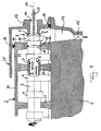
- einen Längsschnitt, dessen entsprechende Ausführung nicht Teil der Erfindung ist durch einen Zylinderkopf im Bereich eines axialen Endbereiches einer Nockenwelle,
- Fig. 2
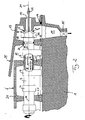
- eine Darstellung, deren entsprechende Ausführung Teil der Erfindung ist wie in
Fig. 1 , jedoch bei einer anderen Ausführungsform einer Zylinderkopfhaube, - Fig. 3
- eine Darstellung, deren entsprechende Ausführung nicht Teil der Erfindung ist wie in
Fig. 2 , jedoch mit einer anderen Nockenwelle und einer anderen Zylinderkopfhaube, - Fig. 4
- eine Detailansicht, deren entsprechende Ausführung nicht Teil der Erfindung ist eines axialen Nockenwellenendes mit einer Mehrkanaleinrichtung.
- Fig. 1
- a longitudinal section, whose corresponding embodiment is not part of the invention by a cylinder head in the region of an axial end portion of a camshaft,
- Fig. 2
- a representation whose corresponding embodiment is part of the invention as in
Fig. 1 but in another embodiment of a cylinder head cover, - Fig. 3
- a representation whose corresponding embodiment is not part of the invention as in
Fig. 2 but with a different camshaft and a different cylinder head cover, - Fig. 4
- a detailed view, whose corresponding embodiment is not part of the invention is an axial camshaft end with a multi-channel device.
Entsprechend
Wie in
Nach Erreichen des Axialspaltes 9 tritt der an der Innenwand 6 des Hohlraumes 5 abgelagerte Ölfilm 7 aufgrund seiner radialen Beschleunigung in den Ölabscheideraum 12 aus und wird dort aufgefangen bzw. gesammelt. Da der Ölabscheideraum 12 zum Ventilraum 11 hin abgeschlossen ist, herrscht in diesem im wesentlichen der gleiche Unterdruck wie im Hohlraum 5, so dass ein Ausfließen des Ölfilmes 7 aus dem Axialspalt 9 nicht behindert wird.After reaching the axial gap 9 of the deposited on the
Der Ölabscheideraum 12 weist gemäß den
Wie in
Zum Ausrichten der Nockenwelle 3 weist diese eine gemäß
Des weiteren ist die Nockenwellenlagereinrichtung 2 zumindest zweiteilig ausgebildet und weist zumindest einen oberen Abschnitt 20 sowie untere Lager 21 auf. Dabei können die Lager 21 fest oder einstückig mit dem Zylinderkopf 1 verbunden oder einteilig zu einem separaten Bauteil, nämlich einer unteren Nockenwellenlagereinrichtung verbunden sein. Der obere Abschnitt 20 der Nockenwellenlagereinrichtung 2 ist abnehmbar ausgebildet, so dass ein einfacher Zugang zur Nockenwelle 3 gewährleistet ist. Zwischen dem Ventilraum 11 und dem Ölsammelraum 12 ist eine Schottwand 22 vorgesehen. Im unterhalb der Nockenwelle 3 gelegenen Bereich trennt ein unterer Teil der Schottwand 22 den Ölabscheideraum 12 vom Ventilraum 11, welcher in der Regel gemäß der Erfindung keine Lageraufgabe zur Lagerung der Nockenwelle 3 zufallen soll. Vielmehr ist hierbei in der Regel zwischen der Schottwand 22 und der Nockenwelle 3 ein in der
Gemäß
Im Unterschied zu
Im Unterschied zu
Gemäß der
Gemäß der
Wie in
Des weiteren umfasst die Mehrkanaleinrichtung 27 ein Tauchrohr 28, das den Auslasskanal bildet, wobei das Tauchrohr 28 einenends mit der Mehrkanaleinrichtung 27 und anderenends mit der Zylinderkopfhaube 13 verbunden ist. Das Tauchrohr 28 ist dabei in die Zylinderkopfhaube 13 eingesteckt und über eine weitere Dichtung 16' dicht mit dieser verbunden.Furthermore, the
Alle in der Beschreibung und in den nachfolgenden Ansprüchen dargestellten Merkmale können sowohl einzeln als auch in beliebiger Form miteinander kombiniert erfindungswesentlich sein.All features described in the description and in the following claims can be essential to the invention, both individually and in any desired form.
Claims (7)
- A cylinder head (1) of an internal combustion engine, having- a camshaft bearing device (2) arranged on the cylinder head (1),- a hollow camshaft (3) which is mounted rotatably in the camshaft bearing device (2) and forms a vent for oil-mist-containing blow-by gases from the crankcase, and is formed as an oil mist separator to separate the oil content from the said gases,- wherein the camshaft (3) penetrates a valve chamber (11) containing the camshaft bearing device (2),- wherein a cylinder head hood (13) axially adjoins at least at one end of the camshaft (3), forming an axial gap (9), which cylinder head hood has a duct (10), which adjoins the cavity (5) of the camshaft (3) coaxially and through which purified blow-by gases can be drawn out of the camshaft (3),- wherein the cylinder head hood (13) is formed in such a manner that it forms an oil collection chamber (12) which is sealed off from the valve chamber (11),characterised- in that a seal (18) is provided on the cylinder head hood (13), which seal bears against the camshaft (3) and seals off the valve chamber (11) from the oil deposition chamber (12),- in that the cylinder head hood (13) is formed from plastic and has a metallic insert (23) in the region of the seal (18).
- The cylinder head according to Claim 1,
characterised by the features- the oil deposition chamber (12) has an oil sump (14) situated in the cylinder head (1),- the oil sump (14) has an outlet valve (15) or lock. - The cylinder head according to Claim 1 or 2,
characterised
in that the axial gap (9) between the camshaft (3) and the cylinder head hood (13) is formed in such a manner that, when the internal combustion engine is operated, oil deposited in the camshaft (3) which is formed as an oil separator can escape into the oil deposition chamber (12). - The cylinder head according to one of the preceding claims,
characterised
in that the cylinder head hood (13) bears in a sealing manner against the cylinder head (1) on one side and against the camshaft (3) or camshaft bearing device (2) on the other side. - The cylinder head according to one of the preceding claims,
characterised
in that a partition (22) is provided between the valve chamber (11) and the oil collection chamber (12). - The cylinder head according to Claim 5,
characterised
in that the partition (22) is an integral component of the cylinder head hood (13). - The cylinder head according to Claim 5 or 6,
characterised
in that a radial gap is provided between the partition (22) and the camshaft (3), which gap prevents direct contact between the partition (22) and the camshaft (3).
Applications Claiming Priority (1)
| Application Number | Priority Date | Filing Date | Title |
|---|---|---|---|
| DE102006012611A DE102006012611A1 (en) | 2006-03-20 | 2006-03-20 | Cylinder head of an internal combustion engine |
Publications (3)
| Publication Number | Publication Date |
|---|---|
| EP1845238A2 EP1845238A2 (en) | 2007-10-17 |
| EP1845238A3 EP1845238A3 (en) | 2009-10-21 |
| EP1845238B1 true EP1845238B1 (en) | 2012-12-19 |
Family
ID=38438191
Family Applications (1)
| Application Number | Title | Priority Date | Filing Date |
|---|---|---|---|
| EP07100955A Expired - Fee Related EP1845238B1 (en) | 2006-03-20 | 2007-01-23 | Cylinder head of combustion engine |
Country Status (3)
| Country | Link |
|---|---|
| US (1) | US7434572B2 (en) |
| EP (1) | EP1845238B1 (en) |
| DE (1) | DE102006012611A1 (en) |
Families Citing this family (20)
| Publication number | Priority date | Publication date | Assignee | Title |
|---|---|---|---|---|
| DE102006024817A1 (en) * | 2006-05-29 | 2007-12-06 | Mahle International Gmbh | Cylinder head of an internal combustion engine |
| JP4884279B2 (en) * | 2007-03-30 | 2012-02-29 | 本田技研工業株式会社 | Internal combustion engine having a breather device |
| US20090272360A1 (en) * | 2007-10-03 | 2009-11-05 | Industrial Technology Research Institute | Lubrication device of four-stroke engines |
| FR2933626B1 (en) * | 2008-07-10 | 2011-01-21 | Filtrauto | DEVICE WITH ROTOR WITH MEDIA COALESCER FOR SEPARATING THE OIL FROM THE CASING GASES OF AN INTERNAL COMBUSTION ENGINE. |
| US8166939B2 (en) * | 2009-03-05 | 2012-05-01 | GM Global Technology Operations LLC | Cam bearing surface of an engine cylinder head that includes an axially extending oil passage |
| DE102009049217A1 (en) * | 2009-10-13 | 2011-04-28 | Mahle International Gmbh | Internal combustion engine with at least one camshaft |
| DE102010024721A1 (en) | 2010-06-23 | 2012-03-29 | Mahle International Gmbh | Cam and associated camshaft |
| DE102010045047A1 (en) * | 2010-09-10 | 2012-03-15 | Thyssenkrupp Presta Teccenter Ag | Method for assembling a motor module |
| DE102011054350A1 (en) | 2011-10-10 | 2013-04-11 | Thyssenkrupp Presta Teccenter Ag | Camshaft and functional elements for a camshaft |
| DE102013108770A1 (en) | 2013-08-13 | 2015-02-19 | Thyssenkrupp Presta Teccenter Ag | Camshaft assembly and camshaft assembly |
| DE102013020770A1 (en) * | 2013-12-11 | 2015-06-11 | Daimler Ag | Cylinder head device for an internal combustion engine |
| CN103790663B (en) * | 2013-12-31 | 2017-01-25 | 广西玉柴机器股份有限公司 | Integrated camshaft |
| JP6442388B2 (en) * | 2015-09-30 | 2018-12-19 | 株式会社クボタ | Engine breather equipment |
| DE102016008299B4 (en) * | 2016-07-06 | 2020-12-31 | Neander Motors Ag | Oil separator for an internal combustion engine |
| US9944373B1 (en) | 2016-09-01 | 2018-04-17 | Brunswick Corporation | Arrangements for lubricating outboard marine engines |
| DE102016224040A1 (en) * | 2016-12-02 | 2018-06-07 | Thyssenkrupp Ag | Method for mounting at least one sealing ring on a camshaft in a bearing lane of an internal combustion engine, and a camshaft with at least one sealing ring mounted in this way |
| US9994294B1 (en) * | 2017-01-13 | 2018-06-12 | Brunswick Corporation | Outboard marine engines having vertical camshaft arrangements |
| US10280812B1 (en) | 2017-04-20 | 2019-05-07 | Brunswick Corporation | Cylinder head and camshaft configurations for marine engines |
| DE102017114646B4 (en) | 2017-06-30 | 2023-08-03 | Thyssenkrupp Ag | Conveyor and compressor element, hollow shaft, internal combustion engine and method for cleaning blow-by gases |
| DE102019000498A1 (en) * | 2019-01-23 | 2020-07-23 | Deutz Aktiengesellschaft | Cylinder head |
Family Cites Families (18)
| Publication number | Priority date | Publication date | Assignee | Title |
|---|---|---|---|---|
| JPS61175213A (en) * | 1985-01-30 | 1986-08-06 | Honda Motor Co Ltd | Breather device in cam casing in engine |
| JPH01158508U (en) * | 1987-02-16 | 1989-11-01 | ||
| JP2504073B2 (en) * | 1987-10-07 | 1996-06-05 | 三菱自動車工業株式会社 | Camshaft with oil separator mechanism |
| JPH01122443A (en) * | 1987-11-07 | 1989-05-15 | Alps Electric Co Ltd | Preparation of ink jet head substrate |
| JP2656515B2 (en) | 1987-12-04 | 1997-09-24 | 株式会社日立製作所 | Mounting device for torsion prevention damper |
| JPH01148009U (en) * | 1988-03-31 | 1989-10-13 | ||
| JPH083784Y2 (en) * | 1989-08-09 | 1996-01-31 | トヨタ自動車株式会社 | Check valve device |
| JPH05149160A (en) * | 1991-11-22 | 1993-06-15 | Kubota Corp | Governor lubricating device of centrifugal governor of engine |
| JPH07150923A (en) * | 1993-12-01 | 1995-06-13 | Nissan Motor Co Ltd | Blow-by gas reducing device of engine |
| JPH08284634A (en) * | 1995-04-07 | 1996-10-29 | Suzuki Motor Corp | Gas-liquid separation device for blow-by gas |
| DE19931740C2 (en) * | 1999-07-08 | 2001-06-13 | Daimler Chrysler Ag | Reciprocating internal combustion engine with a camshaft |
| JP4414070B2 (en) * | 2000-07-11 | 2010-02-10 | 本田技研工業株式会社 | Valve operating device with breather device for engine |
| DE10226695A1 (en) * | 2002-06-15 | 2003-12-24 | Daimler Chrysler Ag | Centrifugal oil separator in a crankcase of an internal combustion engine |
| JP4249504B2 (en) * | 2003-02-17 | 2009-04-02 | マツダ株式会社 | Oil separator structure and oil separator unit |
| JP4344579B2 (en) * | 2003-10-15 | 2009-10-14 | 株式会社マーレ フィルターシステムズ | Cylinder head cover oil separator |
| FR2868468B1 (en) * | 2004-04-06 | 2008-03-21 | Renault Sas | OIL RETURN DEVICE FORMING SIPHON FOR INTERNAL COMBUSTION ENGINE |
| EP1880085B2 (en) | 2005-05-10 | 2013-10-09 | Mahle International GmbH | Centrifugal oil mist separation device integrated in an axial hollow shaft of an internal combustion engine |
| US7219629B2 (en) * | 2005-07-11 | 2007-05-22 | Kawasaki Jukogyo Kabushiki Kaisha | Breathing system in combustion engine |
-
2006
- 2006-03-20 DE DE102006012611A patent/DE102006012611A1/en not_active Withdrawn
-
2007
- 2007-01-23 EP EP07100955A patent/EP1845238B1/en not_active Expired - Fee Related
- 2007-03-09 US US11/716,330 patent/US7434572B2/en not_active Expired - Fee Related
Also Published As
| Publication number | Publication date |
|---|---|
| DE102006012611A1 (en) | 2007-09-27 |
| EP1845238A3 (en) | 2009-10-21 |
| US7434572B2 (en) | 2008-10-14 |
| US20070215075A1 (en) | 2007-09-20 |
| EP1845238A2 (en) | 2007-10-17 |
Similar Documents
| Publication | Publication Date | Title |
|---|---|---|
| EP1845238B1 (en) | Cylinder head of combustion engine | |
| EP2021591B1 (en) | Cylinder head of an internal combustion engine | |
| EP2167235B1 (en) | Internal combustion engine comprising a separator for separating oil mist from the crankcase ventilation gas | |
| EP1880085B2 (en) | Centrifugal oil mist separation device integrated in an axial hollow shaft of an internal combustion engine | |
| EP2021592B1 (en) | Device for ventilating a crankcase | |
| EP2603674B1 (en) | Hollow body with integrated oil separator | |
| EP2406470B1 (en) | Shaft body comprising an integrated oil separator unit | |
| EP2476870B1 (en) | Oil supply device for a combustion engine, in particular for a crankcase of a combustion engine | |
| EP1963626B1 (en) | Camshaft adjuster | |
| DE102016204779B4 (en) | Camshaft adjustment system for an internal combustion engine of a motor vehicle | |
| EP1691043A2 (en) | Device for ventilating an engine crankcase , particularly a V-engine | |
| DE102005034273A1 (en) | Combustion engine e.g. for motor vehicle, has two cam shafts in cylinder head with first cam shaft having longitudinal bore hole for conveying Blow-By-Gas and oil separating device provided | |
| DE19925773B4 (en) | Exhaust gas turbocharger with a emergency oil tank | |
| DE102007054992A1 (en) | Internal combustion engine, has lubricant circuit provided for carrying out lubrication within cylinder head by lubricant mist, which is directly or indirectly discharged from camshaft, which is arranged in cylinder head | |
| EP2545260B1 (en) | Blowby gas separator and engine with the same | |
| WO2011110630A1 (en) | Oil mist separator comprising an oil recirculating channel having a siphon trap | |
| DE102005003113A1 (en) | Separator device for precipitating oil from crankcase ventilating gases in an internal combustion engine has a gas-feeder pipe running at a tangent into a separator/cyclone chamber | |
| EP3526455B1 (en) | Oil container of a combustion engine | |
| DE102016216826A1 (en) | Fluid mist separator and crankcase ventilation device | |
| EP3250797B1 (en) | Internal combustion engine comprising an oil return line having an oil duct | |
| DE102007013348B4 (en) | Cylinder head of an internal combustion engine | |
| DE102012015594A1 (en) | Cylinder head for internal combustion engine of motor car, has seal flange surface, over which cylinder head is connected with suction element, and another seal flange surface, over which cylinder head is connected with exhaust element | |
| DE10049429A1 (en) | Combustion engine with crankcase ventilation has oil absorber bypass for part of the crankcase gases | |
| EP1624162A1 (en) | Method for venting the crankcase of an internal combustion engine and internal combustion engine for performing this method | |
| EP0336893A1 (en) | Plunger pump |
Legal Events
| Date | Code | Title | Description |
|---|---|---|---|
| PUAI | Public reference made under article 153(3) epc to a published international application that has entered the european phase |
Free format text: ORIGINAL CODE: 0009012 |
|
| AK | Designated contracting states |
Kind code of ref document: A2 Designated state(s): AT BE BG CH CY CZ DE DK EE ES FI FR GB GR HU IE IS IT LI LT LU LV MC NL PL PT RO SE SI SK TR |
|
| AX | Request for extension of the european patent |
Extension state: AL BA HR MK YU |
|
| PUAL | Search report despatched |
Free format text: ORIGINAL CODE: 0009013 |
|
| AK | Designated contracting states |
Kind code of ref document: A3 Designated state(s): AT BE BG CH CY CZ DE DK EE ES FI FR GB GR HU IE IS IT LI LT LU LV MC NL PL PT RO SE SI SK TR |
|
| AX | Request for extension of the european patent |
Extension state: AL BA HR MK RS |
|
| 17P | Request for examination filed |
Effective date: 20091105 |
|
| RIN1 | Information on inventor provided before grant (corrected) |
Inventor name: SCHELLHASE, TORSTEN Inventor name: HUETTER, ULRICH |
|
| AKX | Designation fees paid |
Designated state(s): DE FR GB |
|
| 17Q | First examination report despatched |
Effective date: 20110301 |
|
| GRAP | Despatch of communication of intention to grant a patent |
Free format text: ORIGINAL CODE: EPIDOSNIGR1 |
|
| GRAS | Grant fee paid |
Free format text: ORIGINAL CODE: EPIDOSNIGR3 |
|
| GRAA | (expected) grant |
Free format text: ORIGINAL CODE: 0009210 |
|
| AK | Designated contracting states |
Kind code of ref document: B1 Designated state(s): DE FR GB |
|
| REG | Reference to a national code |
Ref country code: GB Ref legal event code: FG4D Free format text: NOT ENGLISH |
|
| REG | Reference to a national code |
Ref country code: DE Ref legal event code: R096 Ref document number: 502007011057 Country of ref document: DE Effective date: 20130214 |
|
| PLBE | No opposition filed within time limit |
Free format text: ORIGINAL CODE: 0009261 |
|
| STAA | Information on the status of an ep patent application or granted ep patent |
Free format text: STATUS: NO OPPOSITION FILED WITHIN TIME LIMIT |
|
| 26N | No opposition filed |
Effective date: 20130920 |
|
| REG | Reference to a national code |
Ref country code: DE Ref legal event code: R097 Ref document number: 502007011057 Country of ref document: DE Effective date: 20130920 |
|
| REG | Reference to a national code |
Ref country code: FR Ref legal event code: PLFP Year of fee payment: 10 |
|
| REG | Reference to a national code |
Ref country code: FR Ref legal event code: PLFP Year of fee payment: 11 |
|
| REG | Reference to a national code |
Ref country code: FR Ref legal event code: PLFP Year of fee payment: 12 |
|
| PGFP | Annual fee paid to national office [announced via postgrant information from national office to epo] |
Ref country code: GB Payment date: 20180130 Year of fee payment: 12 |
|
| PGFP | Annual fee paid to national office [announced via postgrant information from national office to epo] |
Ref country code: FR Payment date: 20180125 Year of fee payment: 12 |
|
| PGFP | Annual fee paid to national office [announced via postgrant information from national office to epo] |
Ref country code: DE Payment date: 20180329 Year of fee payment: 12 |
|
| REG | Reference to a national code |
Ref country code: DE Ref legal event code: R119 Ref document number: 502007011057 Country of ref document: DE |
|
| GBPC | Gb: european patent ceased through non-payment of renewal fee |
Effective date: 20190123 |
|
| PG25 | Lapsed in a contracting state [announced via postgrant information from national office to epo] |
Ref country code: FR Free format text: LAPSE BECAUSE OF NON-PAYMENT OF DUE FEES Effective date: 20190131 Ref country code: DE Free format text: LAPSE BECAUSE OF NON-PAYMENT OF DUE FEES Effective date: 20190801 |
|
| PG25 | Lapsed in a contracting state [announced via postgrant information from national office to epo] |
Ref country code: GB Free format text: LAPSE BECAUSE OF NON-PAYMENT OF DUE FEES Effective date: 20190123 |