EP1844643A1 - Mowing machine - Google Patents
Mowing machine Download PDFInfo
- Publication number
- EP1844643A1 EP1844643A1 EP07004531A EP07004531A EP1844643A1 EP 1844643 A1 EP1844643 A1 EP 1844643A1 EP 07004531 A EP07004531 A EP 07004531A EP 07004531 A EP07004531 A EP 07004531A EP 1844643 A1 EP1844643 A1 EP 1844643A1
- Authority
- EP
- European Patent Office
- Prior art keywords
- mower
- drawbar
- vertical axis
- mowing units
- tractor
- Prior art date
- Legal status (The legal status is an assumption and is not a legal conclusion. Google has not performed a legal analysis and makes no representation as to the accuracy of the status listed.)
- Granted
Links
Images


Classifications
-
- A—HUMAN NECESSITIES
- A01—AGRICULTURE; FORESTRY; ANIMAL HUSBANDRY; HUNTING; TRAPPING; FISHING
- A01D—HARVESTING; MOWING
- A01D75/00—Accessories for harvesters or mowers
- A01D75/30—Arrangements for trailing two or more mowers
- A01D75/303—Arrangements for trailing two or more mowers for mowers positioned one behind the other or side by side
Definitions
- the invention relates to a towed mower as a rotary mower with a large working width in the field of green fodder harvest in agriculture according to the preamble of the independent claim. 1
- the mowing blades are freely or pivotally suspended on the circumference of the mowing discs on a pin.
- the mower blades are only stabilized by the centrifugal force and then mow the green fodder without counter cutting.
- Such mowers are available in many variations such as rear, side, front and towed mowers, but also as self-propelled mower or even under the term direct feed cutting.
- Trailed mowers consist of one or more adjacent cutterbars located at the end of a drawbar attached to the rear of a tractor.
- the mower is driven by the PTO of the tractor and controlled by the on-board hydraulics of the tractor as a rule.
- Mowers of this type are equipped with a chassis, which supports most of the weight of the mower against the ground. In the working position, the mowers are guided laterally next to the tractor on the pivoted drawbar. To transfer the mower in the Transport position for road transport, the drawbar is pivoted back to its transport position, so that the mower runs approximately in the center behind the tractor. If the mower deck is wider than the permissible road traffic profile permits, further measures are required to transfer the mower deck into the road traffic profile.
- Known versions of mowers fold to the cutter bar in an upright position and thereby reduce the transport width.
- Another embodiment pivots the mower about an upright axis by about 90 ° and lifts the mower by a separate chassis whose wheels are lifted in the working position from the ground, from the ground.
- the wheels of the chassis are aligned in the transport position in the direction of travel and aligned in the working position of the mower approximately at right angles to the direction of travel.
- the invention is concerned with the further development of trailed mowers of the aforementioned type from the viewpoint of particularly large working widths, which can still be converted into an acceptable road transport profile.
- the object of the invention is therefore to propose a trailed mower with a large working width, which on the one hand has good steering and guiding properties in its operating position and on the other good steering and guiding properties in its transport position in traffic.
- the invention provides a drawn mower with at least two mower units and at least two staggered rows, which are arranged one behind the other and laterally offset from one another, wherein between the first and last staggered row a chassis is arranged.
- the mowers and the chassis are hinged to the drawbar that the drawbar for transferring the mower can be pivoted to its transport position about a vertical axis by a pivot angle substantially greater than 90 °.
- This process of pivoting involves that the chassis and the mowing units are pivoted relative to the tractor or to the tractor by 180 °, so that the support wheels of the landing gear in the working drive, as far as their direction of rotation rotate opposite to the direction of rotation of the transport. In the reverse pivoting process from the transport to the working position, this applies with the opposite sign.
- this angle of attack enforces the track offset between the mower deck and the tractor. If the angle of attack is identical to zero, this means that the mower is running in the towing vehicle's lane. If the angle of attack exceeds an amount greater than zero degrees, the mower runs at a transverse offset to the track of the tractor and, depending on whether or not the angle of attack relative to the vertical longitudinal center plane assumes a positive or negative angle, the mower runs left or right of the track of the host vehicle.
- the size of the angle of attack and thus the pivot drive for pivoting the drawbar is therefore also in a special way to control the track offset between mower and tractor and this particular even when cornering.
- the vertical axis about which the drawbar is pivoted preferably in the working position in front of the front squadron empires, and in the transport position behind the last squadron empires. Due to the pivoting of the drawbar from the working into the transport position, the direction of travel of the mower deck relative to the tractor is also reversed at the same time, whereby the support wheels of the undercarriage in the transport journey assume the opposite direction of rotation than in the working drive.
- This embodiment of the articulation of the drawbar includes the advantage that the drawbar can still occupy a relatively lower angle of attack to the direction even with large working widths in the working position, whereby the lateral force which transmits the drawbar to the mooring point of the mower and which as a lateral force of the tractor be taken and supported on the ground by the wheels of the tractor can be kept relatively low. This has a favorable effect on the steering characteristics of the Tractor tractor and the towed mower.
- this embodiment has the effect that the tractor and mower length can be shortened significantly, which now has a favorable effect on the steering and caster properties of the team and thus also beneficial to road safety in traffic.
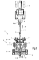
- Fig. 1 shows a mower 1 according to the invention in a plan view in a right-hand working position A with a positive angle ⁇ as right mowing mower 1
- Fig. 2 shows a mower 1 according to the invention in a plan view in a left-side working position B with a negative Angle of attack ⁇ 'as left mowing mower 1.
- the mower 1 has three mowing units 4,5,5', which are hinged to a drawbar 3.
- the mowing unit 4 forms the first staggered row 9 and the mowing mats 5, 5 'form the second staggered row 10.
- Between the first staggered row 9 and the second staggered row 10 is the undercarriage 7 with its supporting wheels 8, 8'.
- the drawbar 3 is with a Coupling device 6 coupled to the lower links of the tractor or a tractor 2. At the front end of the drawbar 3, this is connected in a pivot joint 15 about the vertical axis 16 pivotally connected to the coupling device 6. At the rear end of the drawbar 3, this is pivotally connected to the machine frame 14, which receives the mowing units 4,5,5 'and the chassis 7 in a pivot joint 11 about the vertical axis 12.
- the pivot joint 12 is thereby bridged by an actuator 13, which acts on a lever arm 18 and fixed in the working position and thus locked.
- the actuator 13 is shown in the embodiment as a double-acting hydraulic cylinder.
- the angle of attack ⁇ or ⁇ ' which includes the angle between the vertical longitudinal center plane 19 and the drawbar 3, is decisive for the track offset 21,21' between the track of the towing vehicle 1 and the track of the chassis 7 of the mower 1.
- the mowing units '5.5' can also be equipped with conditioners 17, 17 ', and also with swath-type conveyors, which convey inwards or outwards.
- FIG 3 shows the mower 1 according to the invention in a plan view in an intermediate position C, in which the angle of attack ⁇ , ⁇ 'has disappeared identical to zero, so that the mower runs in the lane of the towing vehicle 1.
- This position of the mower is a working position in which the edge strip of a field can be cleared.
- FIG. 4 shows a mower according to the invention in a plan view in a snapshot during the pivoting of the working position A or B. according to Fig.1 or Fig.2 in the transition position D according to Figure 5.
- the mower is transferred to an intermediate position E according to Figure 5.
- the instantaneous running direction F M of the chassis 8 which changes overall by 180 ° with respect to the towing vehicle 2, changes.
- FIG. 5 shows a mower according to the invention in a plan view in a snapshot after completion of the pivoting of the mowing units 4,5,5 'and the chassis 7 in the position E.
- the mower units are 4.5 in driving and Working direction F seen in front of the vertical axis 12 of the pivot joint 11 of the drawbar 3.
- the mower units are 5,5 'folded into a predominantly vertical position in the final transport position G in Figure 6, whereas the mower 4 in its horizontal Location below the drawbar 3 remains and is lifted off the ground.
- Such embodiments for folding and lifting mowing units 4, 5, 5 ' are known to the person skilled in the art and do not require any further explanation at this position
- FIG. 7 and 8 illustrate the relationship between a positive or negative angle of attack ⁇ , ⁇ 'and a positive or negative swivel angle ⁇ , ⁇ '.
- FIG. 7 illustrates this using the example of the working position according to FIG. 1 and FIG. 8 using the example of FIG.
- the invention provides for a particularly favorable swivel angle range between 120 ° and 150 °.
- the pivot angle ⁇ , ⁇ ' is about 135 °.
- this embodiment of the invention can be in a particularly advantageous design with two mowing units 4,5 or 4,5 'working widths 22 in the range of about 5 meters to about 7 meters and with three mowing units 4,5,5' working widths 22 in the range of about 7 meters to realize about 10 meters, the transport width of 3 meters is not exceeded.
- FIG. 9 illustrates, in contrast, the relationships between the different operating positions A and B and the trailer length 25 in the transport position G.
- a mower according to the invention with three mowing units 4,5,5 ' is shown, this concept according to the invention also on two mowing units 4,5 and 4,5' is applicable.
- the embodiment further mowing units, for example, hinged to variable length boom, which increase the working width A, add, so that the number of mowing units is not limited to three mowing units.
- Drawbar (3) it is also possible to Drawbar (3) to make variable in length by this example is designed telescopic. This allows a further shortening of the trailer length 25 in the transport position.
Landscapes
- Life Sciences & Earth Sciences (AREA)
- Environmental Sciences (AREA)
- Harvester Elements (AREA)
Abstract
Description
Die Erfindung betrifft ein gezogenes Mähwerk als Kreiselmähwerk mit großer Arbeitsbreite im Bereich der Grünfutterernte in der Landwirtschaft gemäß dem Oberbegriff des unabhängigen Anspruchs 1.The invention relates to a towed mower as a rotary mower with a large working width in the field of green fodder harvest in agriculture according to the preamble of the independent claim. 1
Bekannt sind Mähwerke mit umlaufenden Mähwerkzeugen, deren Mähklingen frei- bzw. schwenkbeweglich am Umfang der Mähscheiben an einem Zapfen aufgehängt sind. Die Mähklingen werden erst durch die Zentrifugalkraft stabilisiert und mähen das Grünfutter dann ohne Gegenschneide ab.Are known mowers with rotating mowing tools, the mowing blades are freely or pivotally suspended on the circumference of the mowing discs on a pin. The mower blades are only stabilized by the centrifugal force and then mow the green fodder without counter cutting.
Derartige Mähwerke gibt es in vielfältigen Variationen wie Heck-, Seiten-, Front- und gezogene Mähwerke, aber auch als selbstfahrende Mähwerke oder auch unter dem Begriff Direktfutterschneidwerke.Such mowers are available in many variations such as rear, side, front and towed mowers, but also as self-propelled mower or even under the term direct feed cutting.
Gezogene Mähwerke bestehen aus einem oder mehreren nebeneinander liegenden Mähbalken, die am Ende einer Zugdeichsel angeordnet sind, welche am Heck eines Traktors angehängt wird. Dabei wird das Mähwerk von der Zapfwelle des Traktors angetrieben und im Regelfall von der Bordhydraulik des Traktors gesteuert. Mähwerke dieser Art sind mit einem Fahrwerk ausgestattet, welches den größten Teil der Gewichtskraft des Mähwerks gegenüber dem Boden abstützt. In der Arbeitsstellung werden die Mähwerke seitlich neben dem Traktor an der verschwenkten Zugdeichsel geführt. Zur Überführung des Mähwerks in die Transportstellung für den Straßenverkehr wird die Zugdeichesel in ihre Transportstellung zurück geschwenkt, so dass das Mähwerk etwa mittig hinter dem Traktor läuft. Ist das Mähwerk dann noch breiter als das zulässige Straßenverkehrsprofil dieses zulässt, so werden weitere Maßnahmen zur Überführung des Mähwerks in das Straßenverkehrsprofil erforderlich.Trailed mowers consist of one or more adjacent cutterbars located at the end of a drawbar attached to the rear of a tractor. The mower is driven by the PTO of the tractor and controlled by the on-board hydraulics of the tractor as a rule. Mowers of this type are equipped with a chassis, which supports most of the weight of the mower against the ground. In the working position, the mowers are guided laterally next to the tractor on the pivoted drawbar. To transfer the mower in the Transport position for road transport, the drawbar is pivoted back to its transport position, so that the mower runs approximately in the center behind the tractor. If the mower deck is wider than the permissible road traffic profile permits, further measures are required to transfer the mower deck into the road traffic profile.
Bekannte Ausführungen von Mähwerken verklappen dazu die Mähbalken in eine aufrechte Stellung und vermindern dadurch die Transportbreite. Eine andere Ausführungsart verschwenkt das Mähwerk um eine aufrechte Achse um etwa 90° und hebt das Mähwerk dabei durch ein separates Fahrwerk, dessen Räder in der Arbeitsstellung vom Boden abgehoben sind, vom Boden ab. Dabei sind die Räder des Fahrwerks in der Transportstellung in Fahrtrichtung ausgerichtet und in der Arbeitsstellung des Mähwerks etwa rechtwinklig zur Fahrtrichtung ausgerichtet.Known versions of mowers fold to the cutter bar in an upright position and thereby reduce the transport width. Another embodiment pivots the mower about an upright axis by about 90 ° and lifts the mower by a separate chassis whose wheels are lifted in the working position from the ground, from the ground. The wheels of the chassis are aligned in the transport position in the direction of travel and aligned in the working position of the mower approximately at right angles to the direction of travel.
Die Erfindung befasst sich mit der Weiterentwicklung von gezogenen Mähwerken der vorgenannten Art unter dem Gesichtspunkt besonders großer Arbeitsbreiten, die sich dennoch in ein zulässiges Straßentransportprofil überführen lassen.The invention is concerned with the further development of trailed mowers of the aforementioned type from the viewpoint of particularly large working widths, which can still be converted into an acceptable road transport profile.
Die Aufgabe der Erfindung ist es daher, ein gezogenes Mähwerk mit großer Arbeitsbreite vorzuschlagen, welches einerseits gute Lenk- und Führungseigenschaften in seiner Betriebsstellung und andererseits gute Lenk- und Führungseigenschaften in seiner Transportstellung im Straßenverkehr aufweist.The object of the invention is therefore to propose a trailed mower with a large working width, which on the one hand has good steering and guiding properties in its operating position and on the other good steering and guiding properties in its transport position in traffic.
Gelöst wird die Aufgabe der Erfindung mit den kennzeichnenden Merkmalen des unabhängigen Anspruchs 1. Weitere vorteilhafte Ausgestaltungen der Erfindung sind den abhängigen Ansprüchen, der Beschreibung und den Figurendarstellungen zu entnehmen.The object of the invention is achieved with the characterizing features of
Die Erfindung sieht ein gezogenes Mähwerk mit wenigstens zwei Mäheinheiten und wenigstens zwei Staffelreihen vor, die hintereinander und seitlich versetzt zueinander angeordnet sind, wobei zwischen der ersten und letzten Staffelreihe ein Fahrwerk angeordnet ist. Dabei sind die Mähwerke und das Fahrwerk so an der Zugdeichsel angelenkt, dass die Zugdeichsel zur Überführung des Mähwerks in seine Transportstellung um eine Hochachse um einen Schwenkwinkel wesentlich größer als 90° verschwenkt werden kann. Dieser Vorgang des Verschwenkens beinhaltet, dass das Fahrwerk und die Mäheinheiten relativ zur Zugmaschine bzw. zum Traktor um 180° verschwenkt werden, so dass die Stützräder des Fahrwerks in der Arbeitsfahrt, was deren Drehrichtung anbetrifft, entgegengesetzt zur Drehrichtung der Transportfahrt drehen. Beim umgekehrten Schwenkvorgang von der Transport- in die Arbeitsstellung gilt dieses mit umgekehrtem Vorzeichen. Bedingt dadurch, dass der Anstellwinkel zwischen dem Fahrwerk und der Zugdeichsel die Laufrichtung des Mähwerks bestimmt, erzwingt dieser Anstellwinkel den Spurversatz zwischen dem Fahrwerk des Mähwerks und der Zugmaschine. Verschwindet der Anstellwinkel identisch zu Null, so bedeutet dieses, dass das Mähwerk in der Spur des Zugfahrzeugs läuft. Nimmt der Anstellwinkel einen Betrag größer als Null Grad an, so läuft das Mähwerk in einem Querversatz zur Spur der Zugmaschine, und je nach dem, ob der Anstellwinkel bezogen auf die vertikale Längsmittelebene einen positiven oder negativen Winkel annimmt, läuft das Mähwerk links oder rechts der Spur des Trägerfahrzeugs. Die Größe des Anstellwinkels und damit der Schwenkantrieb zum Verschwenken der Zugdeichsel eignet sich daher auch in besonderer Weise dazu, den Spurversatz zwischen Mähwerk und Zugfahrzeug zu steuern und dieses insbesondere auch in Kurvenfahrten.The invention provides a drawn mower with at least two mower units and at least two staggered rows, which are arranged one behind the other and laterally offset from one another, wherein between the first and last staggered row a chassis is arranged. The mowers and the chassis are hinged to the drawbar that the drawbar for transferring the mower can be pivoted to its transport position about a vertical axis by a pivot angle substantially greater than 90 °. This process of pivoting involves that the chassis and the mowing units are pivoted relative to the tractor or to the tractor by 180 °, so that the support wheels of the landing gear in the working drive, as far as their direction of rotation rotate opposite to the direction of rotation of the transport. In the reverse pivoting process from the transport to the working position, this applies with the opposite sign. Due to the fact that the angle of attack between the chassis and the drawbar determines the running direction of the mower, this angle of attack enforces the track offset between the mower deck and the tractor. If the angle of attack is identical to zero, this means that the mower is running in the towing vehicle's lane. If the angle of attack exceeds an amount greater than zero degrees, the mower runs at a transverse offset to the track of the tractor and, depending on whether or not the angle of attack relative to the vertical longitudinal center plane assumes a positive or negative angle, the mower runs left or right of the track of the host vehicle. The size of the angle of attack and thus the pivot drive for pivoting the drawbar is therefore also in a special way to control the track offset between mower and tractor and this particular even when cornering.
Nach dem Verschwenken in die Transportstellung ist die im Mähbetrieb bzw. in der Arbeitstellung vordere Staffelreihe in der Transportstellung nunmehr die hintere Staffelreihe und die hintere Staffelreihe in der Transportstellung nunmehr die vordere Staffelreihe.After pivoting into the transport position in the mowing operation or in the working position forward staggered row in the transport position now the rear staggered row and the rear staggered row in the transport position now the front staggered row.
Dabei liegt die Hochachse, um welche die Zugdeichsel verschwenkt wird, in der Arbeitstellung vorzugsweise vor der vorderen Staffelreiche, und in der Transportstellung hinter der letzten Staffelreiche. Bedingt durch die Verschwenkung der Zugdeichsel von der Arbeits- in die Transportstellung kehrt sich auch gleichzeitig die Fahrtrichtung des Fahrwerk des Mähwerks relativ zum Traktor um, wodurch die Stützräder des Fahrwerks in der Transportfahrt die entgegengesetzte Drehrichtung als die in der Arbeitsfahrt annehmen. Dieses verkürzt in besonders vorteilhafter Weise die Gespannlänge im Transport, wobei es die Erfindung prinzipiell aber auch zulässt, dass die Hochachse jede andere Lage einnimmt, und somit auch eine Lage zwischen der ersten und zweiten Staffelreihe möglich ist.Here, the vertical axis about which the drawbar is pivoted, preferably in the working position in front of the front squadron empires, and in the transport position behind the last squadron empires. Due to the pivoting of the drawbar from the working into the transport position, the direction of travel of the mower deck relative to the tractor is also reversed at the same time, whereby the support wheels of the undercarriage in the transport journey assume the opposite direction of rotation than in the working drive. This shortens in a particularly advantageous manner, the combination length in transport, the invention in principle but also allows that the vertical axis occupies every other position, and thus a position between the first and second staggered series is possible.
Diese Ausgestaltung der Anlenkung der Zugdeichesel beinhaltet den Vorteil, das die Zugdeichsel auch bei großen Arbeitsbreiten in der Arbeitstellung noch einen relativ geringeren Anstellwinkel zur Fahrtrichtung einnehmen kann, wodurch die Seitenkraft, welche die Zugdeichsel auf den Anhängepunkt des Mähwerks überträgt und welche als Querkraft von dem Traktor aufgenommen und am Boden durch die Räder des Traktors abgestützt werden muss, relativ gering gehalten werden kann. Dieses wirkt sich günstig auf die Lenkeigenschaften des Gespanns Traktor und gezogenes Mähwerk aus.This embodiment of the articulation of the drawbar includes the advantage that the drawbar can still occupy a relatively lower angle of attack to the direction even with large working widths in the working position, whereby the lateral force which transmits the drawbar to the mooring point of the mower and which as a lateral force of the tractor be taken and supported on the ground by the wheels of the tractor can be kept relatively low. This has a favorable effect on the steering characteristics of the Tractor tractor and the towed mower.
In der Transportstellung hingegen wirkt sich diese Ausgestaltung dahingehend aus, dass die Gespannlänge Traktor und Mähwerk erheblich verkürzt werden kann, welches sich nunmehr günstig auf die Lenk- und Nachlaufeigenschaften des Gespanns und damit auch günstig auf die Verkehrssicherheit im Straßenverkehr auswirkt.In the transport position, however, this embodiment has the effect that the tractor and mower length can be shortened significantly, which now has a favorable effect on the steering and caster properties of the team and thus also beneficial to road safety in traffic.
Nähere Einzelheiten der Erfindung sind den nachfolgenden Figurendarstellungen und deren Beschreibungen zu entnehmen.
- Fig. 1
- zeigt ein Mähwerk nach der Erfindung in einer Draufsicht in Arbeitsstellung mit einem positiven Anstellwinkel als rechts mähendes Mähwerk
- Fig. 2
- zeigt ein Mähwerk nach der Erfindung in einer Draufsicht in Arbeitsstellung mit einem negativen Anstellwinkel als links mähendes Mähwerk
- Fig. 3
- zeigt ein Mähwerk nach der Erfindung in einer Draufsicht in einer Zwischenstellung mit einem Anstellwinkel identisch zu Null
- Fig.4
- zeigt ein Mähwerk nach der Erfindung in einer Draufsicht in einer Momentaufnahme während des Verschwenkens von der Arbeitsstellung gemäß Fig.1 in die Transportstellung
- Fig. 5
- zeigt ein Mähwerk nach der Erfindung in einer Draufsicht in einer Momentaufnahme nach Beendigung des Verschwenkens aus der Arbeitsstellung gemäß Fig.1 in die Transportstellung
- Fig. 6
- zeigt ein Mähwerk nach der Erfindung in einer Draufsicht in der Transportstellung
- Fig. 7
- verdeutlicht den Zusammenhang zwischen einem positiven Anstellwinkel und einem positiven Schwenkwinkel
- Fig. 8
- verdeutlicht den Zusammenhang zwischen einem negativen Anstellwinkel und einem negativen Schwenkwinkel.
- Fig. 9
- verdeutlicht die Zusammenhänge zwischen den unterschiedlichen Betriebsstellungen und der verkürzten Gespannlänge in der Transportstellung
- Fig. 1
- shows a mower according to the invention in a plan view in working position with a positive angle as mowing right mowing
- Fig. 2
- shows a mower according to the invention in a plan view in working position with a negative angle of attack as left-mowing mower
- Fig. 3
- shows a mower according to the invention in a plan view in an intermediate position with an angle of attack identical to zero
- Figure 4
- shows a mower according to the invention in a plan view in a snapshot during the pivoting of the working position according to Figure 1 in the transport position
- Fig. 5
- shows a mower according to the invention in a plan view in a snapshot after completion of the pivoting from the working position according to Figure 1 in the transport position
- Fig. 6
- shows a mower according to the invention in a plan view in the transport position
- Fig. 7
- illustrates the relationship between a positive angle and a positive swing angle
- Fig. 8
- illustrates the relationship between a negative angle of attack and a negative swivel angle.
- Fig. 9
- illustrates the relationships between the different operating positions and the shortened trailer length in the transport position
Fig. 1 zeigt ein Mähwerk 1 nach der Erfindung in einer Draufsicht in einer rechtsseitigen Arbeitsstellung A mit einem positiven Anstellwinkel β als rechts mähendes Mähwerk 1 und Fig. 2 zeigt ein Mähwerk 1 nach der Erfindung in einer Draufsicht in einer linkseitigen Arbeitsstellung B mit einem negativen Anstellwinkel β' als links mähendes Mähwerk 1. Das Mähwerk 1 weist drei Mäheinheiten 4,5,5' auf, die an einer Zugdeichsel 3 angelenkt sind. Die Mäheinheit 4 bildet die erste Staffelreihe 9 und die Mähwerke 5,5' bilden die zweite Staffelreihe 10. Zwischen der ersten Staffelreihe 9 und der zweiten Staffelreihe 10 befindet sich das Fahrwerk 7 mit seinen Stützrädern 8,8'. Die Zugdeichsel 3 ist mit einer Kupplungseinrichtung 6 an den Unterlenkern der Zugmaschine bzw. eines Traktors 2 gekoppelt. Am vorderen Ende der Zugdeichsel 3 ist diese in einem Schwenkgelenk 15 um die Hochachse 16 verschwenkbar mit der Kupplungseinrichtung 6 verbunden. Am hinteren Ende der Zugdeichsel 3 ist diese mit dem Maschinengestell 14, welches die Mäheinheiten 4,5,5' und das Fahrgestell 7 aufnimmt, in einem Schwenkgelenk 11 um die Hochachse 12 verschwenkbar verbunden. Das Schwenkgelenk 12 wird dabei von einem Stellantrieb 13 überbrückt, der an einem Hebelarm 18 angreift und in der Arbeitsstellung festgesetzt und damit arretiert ist. Der Stellantrieb 13 ist in dem Ausführungsbeispiel dargestellt als doppeltwirkender Hydraulikzylinder. Der Anstellwinkel β bzw. β', der den Winkel zwischen der vertikalen Längsmittelebene 19 und der Zugdeichsel 3 einschließt, ist bestimmend für den Spurversatz 21,21' zwischen der Spur des Zugfahrzeugs 1 und der Spur des Fahrwerks 7 des Mähwerks 1. Die Mäheinheiten 4,5.5' können auch zusätzlich mit Aufbereitern 17,17', und ebenfalls auch mit Schwadlegern, die nach innen oder außen fördern, ausgestattet sein.Fig. 1 shows a
Fig.3 zeigt das Mähwerk 1 nach der Erfindung in einer Draufsicht in einer Zwischenstellung C, in der der Anstellwinkel β,β' identisch zu Null verschwunden ist, so dass das Mähwerk in der Spur des Zugfahrzeugs 1 läuft. Diese Stellung des Mähwerks ist eine Arbeitsstellung, in der der Randstreifen eines Feldes freigemäht werden kann.3 shows the
Fig.4 zeigt ein Mähwerk nach der Erfindung in einer Draufsicht in einer Momentaufnahme während des Verschwenkens von der Arbeitsstellung A oder B gemäß Fig.1 bzw. Fig.2 in die Übergangsstellung D gemäß Fig.5. Durch die Drehung 20 der Zugdeichsel 3 relativ zum Maschinengestell 14 wird das Mähwerk in eine Zwischenstellung E gemäß Fig.5 überführt. Während des Schwenkvorgangs ändert sich die momentane Laufrichtung FM des Fahrwerks 8, die sich dabei insgesamt gegenüber dem Zugfahrzeug 2 um 180° ändert.4 shows a mower according to the invention in a plan view in a snapshot during the pivoting of the working position A or B. according to Fig.1 or Fig.2 in the transition position D according to Figure 5. By the
Fig.5 zeigt ein Mähwerk nach der Erfindung in einer Draufsicht in einer Momentaufnahme nach Beendigung des Verschwenkens der Mäheinheiten 4,5,5' und des Fahrwerks 7 in der Stellung E. In dieser Stellung befinden sich die Mäheinheiten 4,5 in Fahrt- und Arbeitsrichtung F gesehen vor der Hochachse 12 des Schwenkgelenks 11 der Zugdeichsel 3. Aus dieser Stellung E heraus werden dann die Mäheinheiten 5,5' in eine überwiegend vertikale Lage in die endgültige Transportstellung G gemäß Fig.6 hochgeklappt, wohingegen das Mähwerk 4 in seiner horizontalen Lage unterhalb der Zugdeichsel 3 verbleibt und vom Boden abgehoben wird. Derartige Ausgestaltungen zum Verklappen und Anheben von Mäheinheiten 4,5,5' sind dem Fachmann bekannt und bedürfen an dieser Stell keiner näheren Erläuterung5 shows a mower according to the invention in a plan view in a snapshot after completion of the pivoting of the
Fig.7 und Fig.8 verdeutlichen den Zusammenhang zwischen einem positiven bzw. negativen Anstellwinkel β,β' und einem positiven bzw. negativen Schwenkwinkel α,α'. Fig.7 verdeutlicht dieses am Beispiel der Arbeitsstellung gemäß Fig.1 und Fig.8 am Beispiel der Fig.2.7 and 8 illustrate the relationship between a positive or negative angle of attack β, β 'and a positive or negative swivel angle α, α'. FIG. 7 illustrates this using the example of the working position according to FIG. 1 and FIG. 8 using the example of FIG.
In beiden Figuren Fig.7 und Fig.8 ist die Zugdeichsel 3 zum besseren Verständnis um den Anstellwinkel β bzw. β' um die Hochachse 16 in die Mittelstellung geschwenkt dargestellt, so dass die Mäheinheiten 4,5,5' und das Fahrwerk die Stellung A beibehalten jedoch um den Anstellwinkel β,β' gegenüber der Zugdeichsel 3 und damit gegenüber der vertikalen Längsmittelebene 19 abgewinkelt bleiben. Um nun das Maschinengestell 14 mit den Mäheinheiten 4,5 und dem Fahrwerk 7 in die Zwischenstellung E gemäß Fig.5 zu überführen, muss das gesamte Maschinengestell 14 einschließlich der Mäheinheiten 4,5,5' und des Fahrgestells 7 weiter um den Winkel α bzw. α' um die Hochachse 12 verschwenkt werden.In both figures Fig.7 and Fig.8 is the
Damit gilt für die Beziehung der Schwenkwinkel ![]()
![]()
![]()
![]()
![]()
![]()
Die Erfindung sieht als besonders günstigen Schwenkwinkelbereich einen Bereich zwischen 120° und 150° vor. Vorzugsweise liegt der Schwenkwinkel α,α' bei etwa 135°.The invention provides for a particularly favorable swivel angle range between 120 ° and 150 °. Preferably, the pivot angle α, α 'is about 135 °.
Um die Seitenzugkraft ausgehend von der Anstellung der Zugdeichsel 3 mit dem Anstellwinkel β,β' möglichst gering zu halten, ist es wünschenswert, den Anstellwinkel β,β' dem Betrage nach ebenfalls möglichst gering zu halten. Da aber bei großer vorgegebener Arbeitsbreite 22 des Mähwerks 1 der Spurversatz durch die Arbeitsbreite 22 und die Traktorbreite 24 bereits festgelegt ist, bleiben als Parameter zur Einstellung des Spurversatzes nur die Variablen Zugdeichsellänge 22 und Anstellwinkel β,β'. Der Zugdeichsellänge 22 sind aber wegen der maximal zulässigen Gespannlänge 25 ebenfalls Grenzen gesetzt, so dass die erfinderische Lösung vorsieht, die Gespannlänge 25 bei möglichst großer Arbeitsbreite 22 und geringen Anstellwinkeln β,β' durch die erfinderische Ausgestaltung des Mähwerks zu minimieren.In order to keep the side tensile force as low as possible starting from the employment of the
Mit dieser Ausgestaltung der Erfindung lassen sich in besonders vorteilhafter Bauweise mit zwei Mäheinheiten 4,5 oder 4,5' Arbeitsbreiten 22 im Bereich von etwa 5 Meter bis etwa 7 Meter und mit drei Mäheinheiten 4,5,5' Arbeitsbreiten 22 im Bereich von etwa 7 Meter bis etwa 10 Meter realisieren, wobei die Transportbreite von 3 Meter nicht überschritten wird.With this embodiment of the invention can be in a particularly advantageous design with two mowing
Fig.9 verdeutlicht gegenüberstellend die Zusammenhänge zwischen den unterschiedlichen Betriebsstellungen A und B und der Gespannlänge 25 in der Transportstellung G.FIG. 9 illustrates, in contrast, the relationships between the different operating positions A and B and the
Anhand des zuvor dargelegten Ausführungsbeispiels ist ein Mähwerk nach der Erfindung mit drei Mäheinheiten 4,5,5' dargestellt, wobei dieses Konzept erfindungsgemäß auch auf zwei Mäheinheiten 4,5 bzw. 4,5' anwendbar ist. Ebenso ist es möglich, dem Ausführungsbeispiel weitere Mäheinheiten zum Beispiel angelenkt an längenveränderbaren Ausleger, welche die Arbeitsbreite A vergrößern, hinzuzufügen, so dass die Anzahl der Mäheinheiten keineswegs auf drei Mäheinheiten beschränkt ist. Des weiteren ist es auch möglich, die Zugdeichsel (3) längenveränderbar zu gestalten, indem diese z.B. teleskopierbar ausgeführt ist. Dieses ermöglicht eine weitere Verkürzung der Gespannlänge 25 in der Transportstellung.Based on the embodiment set out above, a mower according to the invention with three
- 11
- MähwerkMower
- 22
- Zugmaschine (Traktor)Tractor (tractor)
- 33
- Zugdeichseldrawbar
- 44
- erste Mäheinheitfirst mowing unit
- 5,5'5.5 '
- zweite Mäheinheitsecond mowing unit
- 66
- Kupplungseinrichtungcoupling device
- 77
- Fahrwerklanding gear
- 8,8'8,8 '
- Stützrädertraining wheels
- 99
- erste Staffelreihefirst season series
- 1010
- zweite Staffelreihesecond season series
- 1111
- Schwenkgelenkpivot
- 1212
- Hochachsevertical axis
- 1313
- Stellantriebactuator
- 1414
- Maschinengestellmachine frame
- 1515
- Schwenkgelenkpivot
- 1616
- Hochachsevertical axis
- 17,17'17,17 '
- AufbereiterDresser
- 1818
- Hebelarmlever arm
- 1919
- vertikale Längsmittelebenevertical longitudinal center plane
- 2020
- Drehrichtungdirection of rotation
- 21,21'21.21 '
- Spurversatzofftrack
- 2222
- Arbeitsbreiteworking width
- 2323
- Deichsellängedrawbar length
- 2424
- Traktorbreitetractor width
- 2525
- Gespannlängetrailer length
- 2626
- Transportbreitetransport width
- AA
- Arbeitstellung (Betriebsstellung) rechtsseitigWorking position (operating position) right side
- BB
- Arbeitstellung (Betriebsstellung) linksseitigWorking position (operating position) left side
- CC
- Arbeitstellung (Betriebsstellung) mittigWorking position (operating position) in the middle
- DD
- Zwischenstellungintermediate position
- Ee
- Zwischenstellungintermediate position
- GG
- Transportstellungtransport position
- FF
- Fahrtrichtungdirection of travel
- FM F M
- Fahrtrichtungdirection of travel
- α,α'α, α '
- Schwenkwinkelswivel angle
- β,β'β, β '
- Anstellwinkelangle of attack
Claims (15)
Applications Claiming Priority (1)
| Application Number | Priority Date | Filing Date | Title |
|---|---|---|---|
| DE102006017324A DE102006017324A1 (en) | 2006-04-11 | 2006-04-11 | mower |
Publications (2)
| Publication Number | Publication Date |
|---|---|
| EP1844643A1 true EP1844643A1 (en) | 2007-10-17 |
| EP1844643B1 EP1844643B1 (en) | 2010-05-26 |
Family
ID=38255048
Family Applications (1)
| Application Number | Title | Priority Date | Filing Date |
|---|---|---|---|
| EP07004531A Not-in-force EP1844643B1 (en) | 2006-04-11 | 2007-03-06 | Mowing machine |
Country Status (3)
| Country | Link |
|---|---|
| EP (1) | EP1844643B1 (en) |
| AT (1) | ATE468743T1 (en) |
| DE (2) | DE102006017324A1 (en) |
Citations (4)
| Publication number | Priority date | Publication date | Assignee | Title |
|---|---|---|---|---|
| GB714086A (en) * | 1951-11-05 | 1954-08-25 | Ransomes Sims & Jefferies Ltd | Improvements in and connected with gang lawn mowers |
| US4415174A (en) * | 1981-12-21 | 1983-11-15 | Gary Koehn | Multiple implement towing apparatus |
| EP0503395A1 (en) * | 1991-03-15 | 1992-09-16 | Maschinenfabrik Bernard Krone GmbH | Mowing machine |
| DE4314250C1 (en) * | 1993-04-30 | 1994-07-21 | Fortschritt Erntemaschinen | Rotor head mower attachment with wide swathe |
Family Cites Families (1)
| Publication number | Priority date | Publication date | Assignee | Title |
|---|---|---|---|---|
| DE4407812A1 (en) * | 1994-03-09 | 1995-09-14 | Popiolek Franz M | Drum mower for agricultural crops |
-
2006
- 2006-04-11 DE DE102006017324A patent/DE102006017324A1/en not_active Withdrawn
-
2007
- 2007-03-06 AT AT07004531T patent/ATE468743T1/en active
- 2007-03-06 DE DE502007003901T patent/DE502007003901D1/en active Active
- 2007-03-06 EP EP07004531A patent/EP1844643B1/en not_active Not-in-force
Patent Citations (4)
| Publication number | Priority date | Publication date | Assignee | Title |
|---|---|---|---|---|
| GB714086A (en) * | 1951-11-05 | 1954-08-25 | Ransomes Sims & Jefferies Ltd | Improvements in and connected with gang lawn mowers |
| US4415174A (en) * | 1981-12-21 | 1983-11-15 | Gary Koehn | Multiple implement towing apparatus |
| EP0503395A1 (en) * | 1991-03-15 | 1992-09-16 | Maschinenfabrik Bernard Krone GmbH | Mowing machine |
| DE4314250C1 (en) * | 1993-04-30 | 1994-07-21 | Fortschritt Erntemaschinen | Rotor head mower attachment with wide swathe |
Also Published As
| Publication number | Publication date |
|---|---|
| EP1844643B1 (en) | 2010-05-26 |
| ATE468743T1 (en) | 2010-06-15 |
| DE502007003901D1 (en) | 2010-07-08 |
| DE102006017324A1 (en) | 2007-10-25 |
Similar Documents
| Publication | Publication Date | Title |
|---|---|---|
| DE2814399C2 (en) | ||
| DE2053073C3 (en) | mower | |
| EP1106051B1 (en) | Mower | |
| EP1389413B1 (en) | Coupling of a lateral mowing unit and its complementary means to a supporting structure for attachment to a tractor or a carrying vehicle | |
| DE4314250C1 (en) | Rotor head mower attachment with wide swathe | |
| DE3406914A1 (en) | TRACTOR OR SIMILAR COMMERCIAL VEHICLE | |
| EP0739582B1 (en) | Rotary tedder | |
| EP2210473B1 (en) | Mower with transverse conveyer | |
| EP0116660B1 (en) | Agricultural machine with a mowing and conditioning device | |
| EP1844643B1 (en) | Mowing machine | |
| EP1008285A1 (en) | Attachable mowing device | |
| DE2349176B2 (en) | Rake | |
| DE3106929A1 (en) | Front-mounted mower with cutting knives moving to and fro | |
| AT523600B1 (en) | deck arrangement | |
| DE69604317T2 (en) | Haymaking machine | |
| EP2055174A1 (en) | Self-propelled agricultural harvester | |
| AT6595U1 (en) | MOWER | |
| DE102006014652A1 (en) | Rotary tedder has at least six rakes mounted on two arms which are angled forward in working position and can be pivoted back about vertical pivots until they are parallel and can then be raised about horizontal pivots to vertical position | |
| DE202006010712U1 (en) | Rotary tedder has at least six rakes mounted on two arms which are angled forward in working position and can be pivoted back about vertical pivots until they are parallel and can then be raised about horizontal pivots to vertical position | |
| EP1527673A1 (en) | Rotary swather | |
| AT7527U1 (en) | PENDANT LARGE MOWER | |
| EP1554919A1 (en) | Coupling of a lateral mowing unit and its complementary means to a supporting structure for attachment to a tractor or a carrier vehicle | |
| DE8318249U1 (en) | Front mower | |
| DE102006047890A1 (en) | Tillage implement with a large working width | |
| DE9109601U1 (en) | Loading wagon |
Legal Events
| Date | Code | Title | Description |
|---|---|---|---|
| PUAI | Public reference made under article 153(3) epc to a published international application that has entered the european phase |
Free format text: ORIGINAL CODE: 0009012 |
|
| AK | Designated contracting states |
Kind code of ref document: A1 Designated state(s): AT BE BG CH CY CZ DE DK EE ES FI FR GB GR HU IE IS IT LI LT LU LV MC MT NL PL PT RO SE SI SK TR |
|
| AX | Request for extension of the european patent |
Extension state: AL BA HR MK YU |
|
| 17P | Request for examination filed |
Effective date: 20080417 |
|
| 17Q | First examination report despatched |
Effective date: 20080526 |
|
| AKX | Designation fees paid |
Designated state(s): AT BE BG CH CY CZ DE DK EE ES FI FR GB GR HU IE IS IT LI LT LU LV MC MT NL PL PT RO SE SI SK TR |
|
| GRAP | Despatch of communication of intention to grant a patent |
Free format text: ORIGINAL CODE: EPIDOSNIGR1 |
|
| GRAS | Grant fee paid |
Free format text: ORIGINAL CODE: EPIDOSNIGR3 |
|
| GRAA | (expected) grant |
Free format text: ORIGINAL CODE: 0009210 |
|
| AK | Designated contracting states |
Kind code of ref document: B1 Designated state(s): AT BE BG CH CY CZ DE DK EE ES FI FR GB GR HU IE IS IT LI LT LU LV MC MT NL PL PT RO SE SI SK TR |
|
| REG | Reference to a national code |
Ref country code: GB Ref legal event code: FG4D Free format text: NOT ENGLISH |
|
| REG | Reference to a national code |
Ref country code: CH Ref legal event code: EP |
|
| REG | Reference to a national code |
Ref country code: IE Ref legal event code: FG4D Free format text: LANGUAGE OF EP DOCUMENT: GERMAN |
|
| REF | Corresponds to: |
Ref document number: 502007003901 Country of ref document: DE Date of ref document: 20100708 Kind code of ref document: P |
|
| REG | Reference to a national code |
Ref country code: NL Ref legal event code: VDEP Effective date: 20100526 |
|
| LTIE | Lt: invalidation of european patent or patent extension |
Effective date: 20100526 |
|
| PG25 | Lapsed in a contracting state [announced via postgrant information from national office to epo] |
Ref country code: SE Free format text: LAPSE BECAUSE OF FAILURE TO SUBMIT A TRANSLATION OF THE DESCRIPTION OR TO PAY THE FEE WITHIN THE PRESCRIBED TIME-LIMIT Effective date: 20100526 Ref country code: LT Free format text: LAPSE BECAUSE OF FAILURE TO SUBMIT A TRANSLATION OF THE DESCRIPTION OR TO PAY THE FEE WITHIN THE PRESCRIBED TIME-LIMIT Effective date: 20100526 |
|
| PG25 | Lapsed in a contracting state [announced via postgrant information from national office to epo] |
Ref country code: IS Free format text: LAPSE BECAUSE OF FAILURE TO SUBMIT A TRANSLATION OF THE DESCRIPTION OR TO PAY THE FEE WITHIN THE PRESCRIBED TIME-LIMIT Effective date: 20100926 Ref country code: FI Free format text: LAPSE BECAUSE OF FAILURE TO SUBMIT A TRANSLATION OF THE DESCRIPTION OR TO PAY THE FEE WITHIN THE PRESCRIBED TIME-LIMIT Effective date: 20100526 Ref country code: SI Free format text: LAPSE BECAUSE OF FAILURE TO SUBMIT A TRANSLATION OF THE DESCRIPTION OR TO PAY THE FEE WITHIN THE PRESCRIBED TIME-LIMIT Effective date: 20100526 Ref country code: LV Free format text: LAPSE BECAUSE OF FAILURE TO SUBMIT A TRANSLATION OF THE DESCRIPTION OR TO PAY THE FEE WITHIN THE PRESCRIBED TIME-LIMIT Effective date: 20100526 |
|
| PG25 | Lapsed in a contracting state [announced via postgrant information from national office to epo] |
Ref country code: CY Free format text: LAPSE BECAUSE OF FAILURE TO SUBMIT A TRANSLATION OF THE DESCRIPTION OR TO PAY THE FEE WITHIN THE PRESCRIBED TIME-LIMIT Effective date: 20100526 Ref country code: PL Free format text: LAPSE BECAUSE OF FAILURE TO SUBMIT A TRANSLATION OF THE DESCRIPTION OR TO PAY THE FEE WITHIN THE PRESCRIBED TIME-LIMIT Effective date: 20100526 |
|
| REG | Reference to a national code |
Ref country code: IE Ref legal event code: FD4D |
|
| PG25 | Lapsed in a contracting state [announced via postgrant information from national office to epo] |
Ref country code: GR Free format text: LAPSE BECAUSE OF FAILURE TO SUBMIT A TRANSLATION OF THE DESCRIPTION OR TO PAY THE FEE WITHIN THE PRESCRIBED TIME-LIMIT Effective date: 20100827 Ref country code: PT Free format text: LAPSE BECAUSE OF FAILURE TO SUBMIT A TRANSLATION OF THE DESCRIPTION OR TO PAY THE FEE WITHIN THE PRESCRIBED TIME-LIMIT Effective date: 20100927 Ref country code: NL Free format text: LAPSE BECAUSE OF FAILURE TO SUBMIT A TRANSLATION OF THE DESCRIPTION OR TO PAY THE FEE WITHIN THE PRESCRIBED TIME-LIMIT Effective date: 20100526 Ref country code: IE Free format text: LAPSE BECAUSE OF FAILURE TO SUBMIT A TRANSLATION OF THE DESCRIPTION OR TO PAY THE FEE WITHIN THE PRESCRIBED TIME-LIMIT Effective date: 20100526 Ref country code: EE Free format text: LAPSE BECAUSE OF FAILURE TO SUBMIT A TRANSLATION OF THE DESCRIPTION OR TO PAY THE FEE WITHIN THE PRESCRIBED TIME-LIMIT Effective date: 20100526 Ref country code: DK Free format text: LAPSE BECAUSE OF FAILURE TO SUBMIT A TRANSLATION OF THE DESCRIPTION OR TO PAY THE FEE WITHIN THE PRESCRIBED TIME-LIMIT Effective date: 20100526 |
|
| PG25 | Lapsed in a contracting state [announced via postgrant information from national office to epo] |
Ref country code: RO Free format text: LAPSE BECAUSE OF FAILURE TO SUBMIT A TRANSLATION OF THE DESCRIPTION OR TO PAY THE FEE WITHIN THE PRESCRIBED TIME-LIMIT Effective date: 20100526 Ref country code: CZ Free format text: LAPSE BECAUSE OF FAILURE TO SUBMIT A TRANSLATION OF THE DESCRIPTION OR TO PAY THE FEE WITHIN THE PRESCRIBED TIME-LIMIT Effective date: 20100526 Ref country code: SK Free format text: LAPSE BECAUSE OF FAILURE TO SUBMIT A TRANSLATION OF THE DESCRIPTION OR TO PAY THE FEE WITHIN THE PRESCRIBED TIME-LIMIT Effective date: 20100526 |
|
| PG25 | Lapsed in a contracting state [announced via postgrant information from national office to epo] |
Ref country code: IT Free format text: LAPSE BECAUSE OF FAILURE TO SUBMIT A TRANSLATION OF THE DESCRIPTION OR TO PAY THE FEE WITHIN THE PRESCRIBED TIME-LIMIT Effective date: 20100526 |
|
| PLBE | No opposition filed within time limit |
Free format text: ORIGINAL CODE: 0009261 |
|
| STAA | Information on the status of an ep patent application or granted ep patent |
Free format text: STATUS: NO OPPOSITION FILED WITHIN TIME LIMIT |
|
| 26N | No opposition filed |
Effective date: 20110301 |
|
| REG | Reference to a national code |
Ref country code: DE Ref legal event code: R097 Ref document number: 502007003901 Country of ref document: DE Effective date: 20110228 |
|
| BERE | Be: lapsed |
Owner name: CLAAS SAULGAU G.M.B.H. Effective date: 20110331 |
|
| PG25 | Lapsed in a contracting state [announced via postgrant information from national office to epo] |
Ref country code: MC Free format text: LAPSE BECAUSE OF NON-PAYMENT OF DUE FEES Effective date: 20110331 |
|
| REG | Reference to a national code |
Ref country code: CH Ref legal event code: PL |
|
| GBPC | Gb: european patent ceased through non-payment of renewal fee |
Effective date: 20110306 |
|
| REG | Reference to a national code |
Ref country code: FR Ref legal event code: ST Effective date: 20111130 |
|
| PG25 | Lapsed in a contracting state [announced via postgrant information from national office to epo] |
Ref country code: MT Free format text: LAPSE BECAUSE OF FAILURE TO SUBMIT A TRANSLATION OF THE DESCRIPTION OR TO PAY THE FEE WITHIN THE PRESCRIBED TIME-LIMIT Effective date: 20100526 Ref country code: BE Free format text: LAPSE BECAUSE OF NON-PAYMENT OF DUE FEES Effective date: 20110331 |
|
| PG25 | Lapsed in a contracting state [announced via postgrant information from national office to epo] |
Ref country code: CH Free format text: LAPSE BECAUSE OF NON-PAYMENT OF DUE FEES Effective date: 20110331 Ref country code: LI Free format text: LAPSE BECAUSE OF NON-PAYMENT OF DUE FEES Effective date: 20110331 Ref country code: FR Free format text: LAPSE BECAUSE OF NON-PAYMENT OF DUE FEES Effective date: 20110331 |
|
| PG25 | Lapsed in a contracting state [announced via postgrant information from national office to epo] |
Ref country code: GB Free format text: LAPSE BECAUSE OF NON-PAYMENT OF DUE FEES Effective date: 20110306 |
|
| REG | Reference to a national code |
Ref country code: AT Ref legal event code: MM01 Ref document number: 468743 Country of ref document: AT Kind code of ref document: T Effective date: 20120306 |
|
| PG25 | Lapsed in a contracting state [announced via postgrant information from national office to epo] |
Ref country code: LU Free format text: LAPSE BECAUSE OF NON-PAYMENT OF DUE FEES Effective date: 20110306 |
|
| PG25 | Lapsed in a contracting state [announced via postgrant information from national office to epo] |
Ref country code: AT Free format text: LAPSE BECAUSE OF NON-PAYMENT OF DUE FEES Effective date: 20120306 |
|
| PG25 | Lapsed in a contracting state [announced via postgrant information from national office to epo] |
Ref country code: TR Free format text: LAPSE BECAUSE OF FAILURE TO SUBMIT A TRANSLATION OF THE DESCRIPTION OR TO PAY THE FEE WITHIN THE PRESCRIBED TIME-LIMIT Effective date: 20100526 Ref country code: BG Free format text: LAPSE BECAUSE OF FAILURE TO SUBMIT A TRANSLATION OF THE DESCRIPTION OR TO PAY THE FEE WITHIN THE PRESCRIBED TIME-LIMIT Effective date: 20100826 |
|
| PG25 | Lapsed in a contracting state [announced via postgrant information from national office to epo] |
Ref country code: HU Free format text: LAPSE BECAUSE OF FAILURE TO SUBMIT A TRANSLATION OF THE DESCRIPTION OR TO PAY THE FEE WITHIN THE PRESCRIBED TIME-LIMIT Effective date: 20100526 Ref country code: ES Free format text: LAPSE BECAUSE OF FAILURE TO SUBMIT A TRANSLATION OF THE DESCRIPTION OR TO PAY THE FEE WITHIN THE PRESCRIBED TIME-LIMIT Effective date: 20100906 |
|
| PGFP | Annual fee paid to national office [announced via postgrant information from national office to epo] |
Ref country code: DE Payment date: 20200320 Year of fee payment: 14 |
|
| REG | Reference to a national code |
Ref country code: DE Ref legal event code: R119 Ref document number: 502007003901 Country of ref document: DE |
|
| PG25 | Lapsed in a contracting state [announced via postgrant information from national office to epo] |
Ref country code: DE Free format text: LAPSE BECAUSE OF NON-PAYMENT OF DUE FEES Effective date: 20211001 |
|
| P01 | Opt-out of the competence of the unified patent court (upc) registered |
Effective date: 20230511 |