EP1844232B1 - Chemische aktivierung eines osmotischen stellglieds oder eines osmotischen motors - Google Patents
Chemische aktivierung eines osmotischen stellglieds oder eines osmotischen motors Download PDFInfo
- Publication number
- EP1844232B1 EP1844232B1 EP06709473A EP06709473A EP1844232B1 EP 1844232 B1 EP1844232 B1 EP 1844232B1 EP 06709473 A EP06709473 A EP 06709473A EP 06709473 A EP06709473 A EP 06709473A EP 1844232 B1 EP1844232 B1 EP 1844232B1
- Authority
- EP
- European Patent Office
- Prior art keywords
- solute
- enclosure
- chamber
- particles
- motor
- Prior art date
- Legal status (The legal status is an assumption and is not a legal conclusion. Google has not performed a legal analysis and makes no representation as to the accuracy of the status listed.)
- Expired - Lifetime
Links
Images


Classifications
-
- F—MECHANICAL ENGINEERING; LIGHTING; HEATING; WEAPONS; BLASTING
- F04—POSITIVE - DISPLACEMENT MACHINES FOR LIQUIDS; PUMPS FOR LIQUIDS OR ELASTIC FLUIDS
- F04B—POSITIVE-DISPLACEMENT MACHINES FOR LIQUIDS; PUMPS
- F04B43/00—Machines, pumps, or pumping installations having flexible working members
- F04B43/02—Machines, pumps, or pumping installations having flexible working members having plate-like flexible members, e.g. diaphragms
-
- F—MECHANICAL ENGINEERING; LIGHTING; HEATING; WEAPONS; BLASTING
- F03—MACHINES OR ENGINES FOR LIQUIDS; WIND, SPRING, OR WEIGHT MOTORS; PRODUCING MECHANICAL POWER OR A REACTIVE PROPULSIVE THRUST, NOT OTHERWISE PROVIDED FOR
- F03G—SPRING, WEIGHT, INERTIA OR LIKE MOTORS; MECHANICAL-POWER PRODUCING DEVICES OR MECHANISMS, NOT OTHERWISE PROVIDED FOR OR USING ENERGY SOURCES NOT OTHERWISE PROVIDED FOR
- F03G7/00—Mechanical-power-producing mechanisms, not otherwise provided for or using energy sources not otherwise provided for
- F03G7/008—Mechanical-power-producing mechanisms, not otherwise provided for or using energy sources not otherwise provided for characterised by the actuating element
- F03G7/015—Actuators using the difference in osmotic pressure between fluids
-
- F—MECHANICAL ENGINEERING; LIGHTING; HEATING; WEAPONS; BLASTING
- F03—MACHINES OR ENGINES FOR LIQUIDS; WIND, SPRING, OR WEIGHT MOTORS; PRODUCING MECHANICAL POWER OR A REACTIVE PROPULSIVE THRUST, NOT OTHERWISE PROVIDED FOR
- F03G—SPRING, WEIGHT, INERTIA OR LIKE MOTORS; MECHANICAL-POWER PRODUCING DEVICES OR MECHANISMS, NOT OTHERWISE PROVIDED FOR OR USING ENERGY SOURCES NOT OTHERWISE PROVIDED FOR
- F03G7/00—Mechanical-power-producing mechanisms, not otherwise provided for or using energy sources not otherwise provided for
- F03G7/025—Mechanical-power-producing mechanisms, not otherwise provided for or using energy sources not otherwise provided for characterised by its use
-
- F—MECHANICAL ENGINEERING; LIGHTING; HEATING; WEAPONS; BLASTING
- F04—POSITIVE - DISPLACEMENT MACHINES FOR LIQUIDS; PUMPS FOR LIQUIDS OR ELASTIC FLUIDS
- F04B—POSITIVE-DISPLACEMENT MACHINES FOR LIQUIDS; PUMPS
- F04B17/00—Pumps characterised by combination with, or adaptation to, specific driving engines or motors
-
- A—HUMAN NECESSITIES
- A61—MEDICAL OR VETERINARY SCIENCE; HYGIENE
- A61F—FILTERS IMPLANTABLE INTO BLOOD VESSELS; PROSTHESES; DEVICES PROVIDING PATENCY TO, OR PREVENTING COLLAPSING OF, TUBULAR STRUCTURES OF THE BODY, e.g. STENTS; ORTHOPAEDIC, NURSING OR CONTRACEPTIVE DEVICES; FOMENTATION; TREATMENT OR PROTECTION OF EYES OR EARS; BANDAGES, DRESSINGS OR ABSORBENT PADS; FIRST-AID KITS
- A61F2/00—Filters implantable into blood vessels; Prostheses, i.e. artificial substitutes or replacements for parts of the body; Appliances for connecting them with the body; Devices providing patency to, or preventing collapsing of, tubular structures of the body, e.g. stents
- A61F2/0004—Closure means for urethra or rectum, i.e. anti-incontinence devices or support slings against pelvic prolapse
- A61F2/0031—Closure means for urethra or rectum, i.e. anti-incontinence devices or support slings against pelvic prolapse for constricting the lumen; Support slings for the urethra
- A61F2/0036—Closure means for urethra or rectum, i.e. anti-incontinence devices or support slings against pelvic prolapse for constricting the lumen; Support slings for the urethra implantable
-
- A—HUMAN NECESSITIES
- A61—MEDICAL OR VETERINARY SCIENCE; HYGIENE
- A61F—FILTERS IMPLANTABLE INTO BLOOD VESSELS; PROSTHESES; DEVICES PROVIDING PATENCY TO, OR PREVENTING COLLAPSING OF, TUBULAR STRUCTURES OF THE BODY, e.g. STENTS; ORTHOPAEDIC, NURSING OR CONTRACEPTIVE DEVICES; FOMENTATION; TREATMENT OR PROTECTION OF EYES OR EARS; BANDAGES, DRESSINGS OR ABSORBENT PADS; FIRST-AID KITS
- A61F2/00—Filters implantable into blood vessels; Prostheses, i.e. artificial substitutes or replacements for parts of the body; Appliances for connecting them with the body; Devices providing patency to, or preventing collapsing of, tubular structures of the body, e.g. stents
- A61F2/02—Prostheses implantable into the body
- A61F2/08—Muscles; Tendons; Ligaments
- A61F2002/0894—Muscles
-
- A—HUMAN NECESSITIES
- A61—MEDICAL OR VETERINARY SCIENCE; HYGIENE
- A61M—DEVICES FOR INTRODUCING MEDIA INTO, OR ONTO, THE BODY; DEVICES FOR TRANSDUCING BODY MEDIA OR FOR TAKING MEDIA FROM THE BODY; DEVICES FOR PRODUCING OR ENDING SLEEP OR STUPOR
- A61M60/00—Blood pumps; Devices for mechanical circulatory actuation; Balloon pumps for circulatory assistance
- A61M60/10—Location thereof with respect to the patient's body
- A61M60/122—Implantable pumps or pumping devices, i.e. the blood being pumped inside the patient's body
- A61M60/126—Implantable pumps or pumping devices, i.e. the blood being pumped inside the patient's body implantable via, into, inside, in line, branching on, or around a blood vessel
- A61M60/148—Implantable pumps or pumping devices, i.e. the blood being pumped inside the patient's body implantable via, into, inside, in line, branching on, or around a blood vessel in line with a blood vessel using resection or like techniques, e.g. permanent endovascular heart assist devices
Definitions
- the present invention relates to devices that can be used as actuators or motors that are simple to make, that use a low cost fuel, and that emit little or no waste.
- the present invention relates to devices that can serve as actuators or motors adapted to operate within a biological medium such as the human body or an animal body.
- Such actuators and motors have applications in the medical field for example to overcome the deficiency of a natural muscle.
- the muscles that can be replaced or assisted, temporarily or permanently, are, for example, the heart muscle, the respiratory muscles, the sphincters and the smooth or striated muscles, in particular skeletal muscles.
- Such actuators and motors also find applications in fields other than medical.
- an engine can be used in all areas in which a low generation of waste is an important factor in the choice of the engine. It may be, for example, the automotive field where we seek to reduce the most possible polluting waste produced by the engine used for driving the wheels of the vehicle.
- the patent application EP-A-1481165 in the name of the applicant, describes an actuator and an osmotic motor whose operation can be controlled more accurately.
- the patent application EP-A-1481165 provides the use of microorganisms that are contained in an enclosure permeable to a solvent and not permeable to a first solute.
- the microorganisms are adapted to transform a second solute into the first solute.
- a deformable chamber is connected to the chamber and can increase in volume under the action of the solvent entering the chamber by osmosis as the microorganisms provide the first solute.
- a disadvantage of such an actuator and such an osmotic engine is that the maintenance of life of the microorganisms imposes binding conditions of use. More precisely, it is necessary to dissolve in the solvent in which the microorganisms are disposed substances essential for the metabolism of microorganisms, for example glucose and oxygen. It is also necessary to provide for the disposal of waste produced by cellular metabolism, especially carbon dioxide. Moreover, it is necessary to maintain many parameters such as the temperature or the pH of the solvent in which the microorganisms are arranged in generally very small ranges outside of which the microorganisms can not survive.
- the present invention is an actuator and an osmotic motor whose implementation is simplified.
- the present invention also provides an actuator and an osmotic motor that can operate for a long time without requiring maintenance.
- the present invention aims to use, instead of microorganisms provided in the European patent application EP-A-1,481,165 , one or more catalysts adapted to promote a reaction of transformation of a compound into another compound.
- catalysts may correspond, for example, to enzymes which are proteins having a very high catalytic power.
- the present invention is characterized by greater flexibility in the operating conditions of the actuator and the osmotic motor. Indeed, the catalysts being non-living compounds, the constraints to ensure their integrity are less important than those aimed at the survival of microorganisms.
- the present invention provides an actuator comprising an enclosure having a non-permeable wall with a first solute and permeable to a solvent and containing, at least temporarily, a catalyst adapted to promote the transformation of at least one second solute into the first. solute to vary the osmotic pressure in the enclosure; and a deformable chamber connected to the chamber, said chamber being adapted to increase in volume under the action of the solvent moving from the chamber into the chamber by osmosis or said chamber being intended to be disposed in contact with the solvent, said chamber being adapted to increase in volume under the action of the solvent penetrating the chamber by osmosis.
- said wall of the enclosure is permeable to the second solute.
- said wall of the chamber is non-permeable to the second solute, the catalyst being adapted to promote the transformation of a number of particles of the second solute into a greater or smaller number of particles. of the first solute.
- the present invention also provides a motor comprising an actuator as previously described, wherein the chamber comprises a return means which opposes increasing the volume of the chamber and a controllable means for lowering the osmotic pressure in the chamber .
- the wall of the chamber is non-permeable to the second solute, the catalyst being adapted to promote the transformation of a number of particles of the second solute into a higher number of particles of the first solute.
- the engine further comprises an additional enclosure having a wall permeable to the solvent and non-permeable to the first and second solutes and containing an additional catalyst adapted to promote the transformation of a number of particles of the first solute into a smaller number of particles of the second. solute, said additional enclosure being connected to the chamber by a valve.
- the wall of the chamber is non-permeable to the second solute, the catalyst being adapted to promote the transformation of a number of particles of the second solute into a higher number of particles of the first solute.
- the enclosure is disposed in a deformable envelope containing the solvent and the first solute, the enclosure containing an additional catalyst adapted to promote the transformation of a number of particles of the first solute into a smaller number of particles of the second solute, the means for lowering the osmotic pressure in the chamber being a valve adapted to put in communication the chamber and the envelope.
- the present invention also provides a motor comprising an actuator as described above, wherein the enclosure is at least partly deformable and is connected to the chamber at the wall.
- the engine comprises a first supply means in the enclosure of the catalyst, and a second supply means in the enclosure of a catalyst additional adapted to promote the transformation of the first solute into the second solute.
- the wall is permeable to the second solute.
- the catalyst is adapted to promote the transformation of a number of particles of the second solute into a smaller number of particles of the first solute and the additional catalyst is adapted to promote the transformation of a number of particles of the first solute into a larger number. high particles of the second solute.
- the second solute is a compound comprising an amine function, the first solute being a complex of the second solute and an additional solute comprising an aldehyde function, the wall being non-permeable to additional solute.
- the catalyst is the hydrogen ion, the additional catalyst being the hydroxyl ion.
- the first supply means comprises an additional chamber intended to receive a solvent containing glucose, the additional chamber containing glucose oxidase enzymes adapted to promote the oxidation of glucose to provide gluconate ions. and hydrogen ions.
- the second supply means comprises an additional enclosure intended to receive a solvent containing urea, the additional enclosure containing urease enzymes adapted to promote the oxidation of urea to provide ammonium ions and carbon dioxide.
- the present invention also provides a pH-variable osmolarity solution comprising a first substance having an amine function and a second substance having an aldehyde function.
- the first substance is urea and the second substance is vanillin.
- the second substance is a derivative of vanillin
- an osmotic motor 10 comprises an enclosure 12 consisting of a hollow fiber bundle with semi-permeable walls 14, for example of the type used for dialysis operations.
- the wall of the fibers 14 has a given cutoff threshold, for example of the order of 200 Daltons, that is to say that it allows particles having a molecular weight substantially less than 200 Daltons to pass, that is, that is 200 g / mol.
- Each fiber has, for example, a diameter of the order of 200 microns.
- the fiber bundle 14 is maintained at a first end by a first connecting ring 16, for example by means of a bonding zone 18.
- the ring 16 comprises an opening 20 closed by a plug 21.
- the second end of the fiber bundle 14 is held by a second connecting ring 22, for example via a bonding zone 24.
- the chamber 12 is fixed at the level of the second connecting ring 22 at one end of a cylindrical body 28 in which a movable piston 30 can slide.
- the movable piston 30 and the cylindrical body define an expansion chamber 31.
- return means 32 exerts on the piston 30 a tensile force tending to bring it back to a rest position.
- the cylindrical body 28 comprises a discharge valve 34 communicating with the outside of the engine 10.
- the fibers 14 there is a catalyst adapted to promote a synthesis reaction of an osmotically active substance X from a substance Y, the substance Y having a molar mass lower than the molar mass of the substance X
- the cut-off point of the fibers 14 is set to prevent the passage of the substance X and the catalyst but to allow the passage of the substance Y, while the cutoff threshold of the membrane 25 is fixed to allow the passage of the substance X but to block the catalyst.
- the engine 10 is placed in an ambient medium comprising a solvent in which the substance Y is dissolved.
- the Figure 1A represents the motor 10 at the beginning of a cycle.
- the piston 30 is in the rest position, the volume of the expansion chamber 31 is minimal, and the discharge valve 34 is closed.
- the catalyst promotes the manufacture of the substance X from the substance Y, which tends to increase the osmotic pressure inside the fiber bundle 14.
- the solvent of the ambient medium penetrates the fibers 14 and in the expansion chamber 31, thus moving the piston 30.
- the displacement of the piston 30 tends the spring 32, for storing mechanical energy.
- the expansion chamber 31 is shown in maximum expansion.
- the evacuation valve 34 then opens.
- the pressure inside the expansion chamber 31 is equalized with the pressure of the ambient medium.
- the spring 32 returns the piston 30 in the rest position by evacuating, through the discharge valve 34, the solvent of the expansion chamber 31 in the environment.
- the mechanical energy stored in the spring 32 is thus recovered.
- the valve 34 is finally closed, thus completing the engine cycle.
- the piston 32 may be connected to an external element to which it is desired to transmit mechanical energy.
- substance X is a glucose polymer having a high number of glucose molecules, for example dextran
- substance Y is an oligomer (which, by definition, comprises a small number of monomer units) of minimum molecular weight glucose equal to 342 g / mol.
- the catalyst can then be an enzyme dextransucrase, that is to say an enzyme that promotes the synthesis of dextran from a glucose oligomer.
- the expansion chamber 31 is formed by a cylindrical body in which a piston slides.
- the expansion chamber 31 may be made differently.
- the Figures 2A and 2B represent a structural variant of the expansion chamber 31 of the engine 10 of the first embodiment.
- the expansion chamber 31 corresponds to the space defined between an inner casing 36 and an outer casing 37 in the manner of an air chamber.
- the inner casing 36 is deformable and extensible and surrounds a deformable body 38.
- the outer casing 37 is flexible and inextensible. She closes again the inner casing 36 and is connected to the connecting ring 22 of the enclosure 12.
- the discharge valve 34 is disposed on the connecting ring 22.
- the deformable body 38 may be the human heart and the envelopes may define expansion chambers 31 in the form of strands surrounding the heart.
- a cycle of the engine 10 according to the variant of the first embodiment is as follows.
- the Figure 2A represents the motor 10 at the beginning of the cycle.
- the volume of the expansion chamber 31 is minimal, the deformable body 38 being in maximum expansion, which may correspond to a heart diastole.
- the evacuation valve 34 is then closed.
- the catalyst promotes the formation of the substance X, which causes, by osmosis, the introduction of solvent into the expansion chamber 31.
- the inner casing 36 is deformed and compresses the deformable body 38.
- the deformable body 38 is compressed to the maximum, which may correspond to a heart in systole.
- the solvent evacuates the expansion chamber 31 allowing expansion of the deformable body 38, which completes the cycle.
- the expansion chamber consists of an elastic envelope enclosing the fibers which are arranged, for example, spirally, the two connecting rings being sealed.
- the fibers tend to straighten and deform the elastic envelope.
- An evacuation valve is provided at a connecting ring. At the opening of the valve, the pressure inside the fibers decreases and the envelope tends to return to its original shape.
- the enclosure may be connected to the expansion chamber by a flexible conduit.
- a flexible conduit This makes it possible advantageously to dispose the chamber in an ambient environment which is favorable for the supply of solvent in which dissolves the substance Y, and to place the expansion chamber in a place where it is desired to have mechanical energy.
- the chamber can be placed in a fatty tissue, or on the vascular network.
- the fibers may be arranged to form a hollow tube, leaving in its center a cylindrical space for the circulation of a fluid such as blood.
- the connecting rings may be toric in shape and placed against the wall of a blood vessel.
- One of the toric junction rings communicates with the dilatation chamber through the flexible conduit that perforates the blood vessel.
- FIGS. 3A to 3C represent a second embodiment of an osmotic motor according to the invention.
- the engine 40 includes the engine components of the first embodiment and the references associated therewith are retained.
- the motor 40 comprises a first enclosure 12 of the type described above and a second enclosure 42.
- the second enclosure 42 comprises a second fiber bundle 44 held at the ends by connecting rings 45, 46 by means of bonding zones 47, 48.
- the second chamber 42 is fixed on the cylindrical body 28 at the valve 34, by the junction ring 45 which comprises a membrane 49 separating the expansion chamber 31 of the second fibers 44.
- the second chamber 42 communicates, at the level of the ring 46 via a membrane 52, with a tank 54 deformable and sealed.
- a first catalyst C 1 promotes the formation of a substance Y from a substance X, so that from an elementary particle of the substance X, it is produces more than one elemental particle of the substance Y.
- a second catalyst C 2 promoting the formation of the substance X from the substance Y, so that to produce an elementary particle of substance X, more than one elemental particle of substance Y is used.
- substance X is a glucose polymer having a high number of glucose molecules, for example dextran
- substance Y is a glucose oligomer.
- the second catalyst C 2 can then be a dextransucrase enzyme, that is to say an enzyme which promotes the synthesis of dextran from a glucose oligomer and the first catalyst C 1 can then be a dextranase enzyme, that is, an enzyme that promotes degradation of dextran to glucose or glucose oligomers.
- the walls of the fiber bundles 14, 44 have a cutoff threshold lower than the molar mass of the substances X and Y.
- the cut-off threshold is of the order of 100 Daltons when the substance Y is glucose or an oligomer of glucose and the substance X is dextran.
- the membranes 25, 49 and 52 have cut-off thresholds greater than 1000 Daltons, so as to pass the X and Y substances and maintain the catalysts in the respective fiber bundles 14, 44.
- the motor 40 In normal operation, the motor 40 is placed in a solvent.
- the operating cycle of the osmotic motor 40 according to the invention is as follows.
- the figure 3A represents the engine 40 at the beginning of the cycle.
- the valve 34 is closed.
- the concentrations of the substance Y are identical in the reservoir 54 and the expansion chamber 31, as are the concentrations of the substance X.
- the catalyst C 1 promotes the formation of the substance Y, which which increases the osmotic pressure in the expansion chamber 31.
- the solvent enters the first fiber bundle 14 and then in the expansion chamber 31, thus displacing the piston 30 and storing mechanical energy by the tensioning of the spring 32
- the catalyst C 2 promotes the formation of the substance X, which decreases the osmotic pressure in the reservoir 54.
- the reservoir 54 decreases in volume without producing useful work since nothing does not oppose this decrease.
- the figure 3B represents the motor 10 at the end of the step described above, the expansion chamber 31 having a maximum volume.
- the valve 34 then opens.
- the concentrations of substance X and substance Y are balanced in the fiber bundles 14, 44, the expansion chamber 31 and the tank 54.
- the osmotic pressures equilibrate in the different compartments.
- the piston 30 therefore descends under the action of the spring 32 to the position shown on the figure 3C .
- the reservoir 54 expands by filling with liquid, the work necessary to expand the reservoir 54 being negligible compared with that provided by the spring 32, the pressures in the environment being low compared to those present in the expansion chamber 31.
- the valve 34 is then closed, which closes the cycle.
- the second embodiment is particularly advantageous insofar as the exchanges between the motor 40 and the ambient medium are reduced compared to the first embodiment.
- the osmotically active substance X for example dextran
- the substance Y for example a glucose oligomer
- the discharge valve 34 is open and most of the substance X formed is released into the environment.
- the substance X produced for example dextran
- the human body which can be problematic.
- the Figures 4A to 4C represent a third embodiment of the osmotic motor 60 according to the invention.
- the engine 60 includes the components of the engine 10 of the first embodiment and the references associated therewith are retained.
- the chamber 12 is disposed in a deformable and tight envelope 61 which closes on the connecting ring 22 and the exhaust valve 34.
- the envelope 61 is filled with a solvent.
- the envelope 61 may be arranged in a rigid housing 64 perforated so as not to prevent deformation of the envelope 61.
- first catalyst C 1 promoting the formation of a substance Y (for example a glucose oligomer) from a substance X (for example dextran), so that from an elementary particle of X, more than one elementary particle of Y is produced.
- a second catalyst C 2 promoting the formation of substance X from the substance Y, so that to produce an elementary particle of substance X, more than one elementary particle of substance Y is used.
- the membranes of the fiber bundle 14 have a cutoff threshold lower than the molar mass of the substances X and Y.
- the cutoff threshold is of the order of 100 Daltons when the substance Y is glucose or a glucose oligomer, and substance X dextran.
- An operating cycle of the engine 60 according to the third embodiment is as follows.
- the Figure 4A represents the motor 60 at the beginning of a cycle.
- the valve 34 is closed.
- the envelope 61 is at its maximum volume. All the compartments contain a solvent in which the substances X and Y are in solution.
- the X concentrations are substantially balanced between the envelope 61 and the expansion chamber 31.
- the first catalyst C 1 promotes the formation of the substance Y, which increases the osmotic pressure in the beam 14 and the expansion chamber 31.
- the second catalyst C 2 promotes the formation of the substance X, reducing the osmotic pressure inside the casing 61. Solvent exchanges occur, the solvent passing to the fiber bundle 14 and from there to the expansion chamber 31 causing the displacement of the piston 30.
- the piston is in the ascending phase.
- the Figure 4B represents the motor 60 at the end of the previously described step.
- the concentration of substance X is minimal in the fiber bundle 14 and maximum within the envelope 61.
- the substance concentration Y is maximum in the fiber bundle 14 and minimum in the envelope 61 .
- the evacuation valve 34 is then opened, which puts the expansion chamber 31 in direct communication with the casing 61.
- the pressure in the expansion chamber 31 collapses and the return spring 32 brings the piston 30 back to the initial position evacuating. the solvent of the expansion chamber 31 to the casing 61.
- the piston is said to be in a descending phase.
- the fiber bundle 14 is thus placed in communication with the interior of the envelope 61.
- the concentrations of substances X and Y are equalized between these two compartments.
- the figure 4C represents the motor 60 at the end of the downward phase of the piston 30.
- the valve 34 is then closed, which closes the cycle.
- a variant of the third embodiment of the osmotic motor can be used as a motor for driving the wheels of a motor vehicle.
- the spring is removed and the piston is connected, for example, by a connecting rod to a drive shaft of the wheels in a similar manner to the connection between a piston of a heat engine and the crankshaft.
- the driving force corresponds to the ascending phase of the piston, that is to say to the expansion phase of the expansion chamber.
- the piston encounters only a small resistance, corresponding to the passage of the solvent through the discharge valve of the expansion chamber.
- at least two osmotic motors can be connected in parallel to drive the motor shaft so that the expansion chambers of the motors work in opposition, one being in the expansion phase when the other is in phase of expansion. contraction.
- Such a motor can, in addition, be used to recover energy during braking of the vehicle.
- it comprises an additional valve, called the supply valve disposed between the first fiber bundle and the expansion chamber.
- the feed valve When operating the motor for driving the wheels, the feed valve is open so that the motor operates as previously described.
- enclosures 12 and 42 may be made other than by a bundle of fibers. They can have any shape allowing a good exchange of solutes and solvent on both sides of the wall of the enclosure.
- valve 34 may have any type of known structure.
- the openings and closures of the valve can for example be controlled by a device external to the motor, synchronously or not, or be triggered automatically by the actual structure of the valve when the pressure in an engine compartment exceeds a given value.
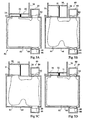
- FIGS 5A to 5D represent a fourth embodiment of the osmotic motor 80 according to the invention.
- the engine 80 includes some components of the engine 60 of the third embodiment and the references associated therewith are retained.
- a valve 82 is disposed at the rigid casing 64 and is adapted to communicate, when open, the contents of the casing 61 with the contents of a chamber 84.
- a valve 86 is disposed at the level of the rigid casing 64 and is adapted to communicate, when open, the contents of the envelope 61 with the contents of an enclosure 88.
- the envelope 61 contains substances U and V, dissolved in a solvent and which are capable of reacting in the presence of H + ions, that is to say at a sufficiently acidic pH, to form a substance Z.
- H + ion plays a role similar to that of a catalyst of the reaction of synthesis of the substance Z.
- the inverse reaction according to which the substance Z is degraded to give again the substances U and V is likely to occur in the presence of ions OH - that is to say at a sufficiently basic pH.
- the OH- ion plays a role similar to that of a catalyst for the degradation reaction of the substance Z.
- the membrane 25 has a cut-off threshold sufficiently low to block the substances U and V which are therefore osmotically active.
- the valves 82, 86 are associated with membranes, not shown, which have a cutoff threshold such that they block the substances U and V.
- the enclosure 84 contains an acid solution and the enclosure 88 contains a basic solution.
- Substances U, V and Z must be soluble in the solvent and, if possible, biocompatible in the case of a medical application.
- the substance U is a molecule comprising a primary amine function (-NH 2 function) and the substance V is a molecule comprising an aldehyde function (-CHO function).
- Complex formation reactions from an amine-functional U substance and an aldehyde-functional substance V are described in the literature. Advanced Organic Chemistry: Reactions, Mechanisms and Structure, Third Edition, J. March, John Wilez and Sons, New York (1985), PP 796-798 and Advanced Organic Chemistry, Part B: Reactions and Synthesis, Third Edition, FA Carey and RJ Sundberg, Plenum Press, New York (1990), pp 30-31 .
- the substance U can be urea with a molecular weight of 60 g / mol
- the substance V can be vanillin with a molecular weight of 152 g / mol.
- the membrane 25 then has a cutoff threshold of 50 Daltons.
- Substance Z corresponds to a urea-vanillin complex.
- compound V is a vanillin derivative having the following formula: where R is a carbon group (R corresponding to the hydroxyl group -OH in the case of vanillin).
- the dilatation chamber 31 contains a substance A, dissolved in the solvent, which is osmotically active.
- the membrane 25 has a cutoff threshold sufficiently low to block substance A.
- substance A is dextran.
- An operating cycle of the motor 80 according to the fourth embodiment is as follows.
- the Figure 5A represents the motor 80 at the beginning of a cycle.
- the envelope 61 is at its maximum volume.
- the concentrations of the substances U and V and the concentration of the substance A are initially chosen so that the osmotic pressures in the expansion chamber 31 and in the casing 61 are balanced, the piston 30 remaining fixed.
- the valve 86 is closed and the valve 82 is then open. H + ions spread in the envelope 61 causing a decrease in pH.
- the valve 82 is closed.
- the formation reaction of the substance Z from the substances U and V is then favored.
- the osmotic pressure in the envelope 61 decreases relative to the osmotic pressure in the expansion chamber 31 which does not vary. A transfer of solvent therefore occurs, the solvent passing from the envelope 61 to the expansion chamber 31 through the membrane 25, causing the displacement of the piston 30.
- the piston 30 is in the ascending phase.
- the Figure 5B represents the motor 80 at the end of the ascending phase of the piston 30.
- valve 86 was opened so as to put in communication the contents of the envelope 61 with the contents of the enclosure 88.
- OH- ions spread in the envelope 61 causing an increase in the pH.
- the valve 86 is closed.
- the degradation reaction of the substance Z is then favored, resulting in the increase of the number of osmotically active particles in the envelope 61.
- the increasing osmotic pressure in the envelope 61 a new transfer of solvent occurs, solvent passing from the dilation chamber 31 towards the envelope 61 through the membrane 25.
- the action of the spring 32 promotes the removal of the solvent from the expansion chamber.
- the spring 32 may not be present, the piston moving by suction.
- the piston 30 is said in down phase.
- the figure 5D represents the motor 80 at the end of the downward phase of the piston 30, which closes the cycle.
- the concentrations of the substances U and V in the envelope 61 are then substantially identical to the concentrations at the beginning of the cycle.
- the membrane 25 is only impermeable to the substance V but permeable to the substance U.
- the substances A, Z and V are osmotically active.
- the substance U is free to diffuse through the membrane 25 and is therefore not osmotically active.
- the membrane 25 has for example a cutoff threshold of the order of 100 Daltons.
- Substances U and V then have the additional characteristic that the formation of a particle of substance Z uses, at least on average, more than one particle of substance V. This is verified when substance U is urea and substance V is vanillin. Indeed, a molecule of the urea-vanillin complex is on average obtained from a molecule of urea and more than one molecule of vanillin (one or two vanillin molecules grafted onto the urea according to the steric hindrance ). Such a substitution reaction is described in the previously mentioned reference " Advanced Organic Chemistry: Reactions, Mechanisms and Structure, Third Edition, J. March, John Wilez and Sons, New York (1985), pp 798 .
- an operating cycle of the motor 80 is as follows.
- the envelope 61 is at its maximum volume.
- the concentration of substance V and the concentration of substance A are initially chosen from so that the osmotic pressures in the expansion chamber 31 and in the casing 61 are balanced, the piston 30 remaining fixed.
- the valve 86 is closed and the valve 82 is then open.
- the H + ions spread in the envelope 61 causing a decrease in the pH in the envelope 61.
- the formation reaction of the substance Z from the substances U and V is then favored, the substance U present in the expansion chamber. 31 passing through the envelope 61 to participate in the reaction.
- the formation of a particle of the substance Z requiring more than one particle of the substance V, the number of osmotically active particles decreases in the envelope 61 relative to the expansion chamber 31.
- the osmotic pressure in the envelope 61 therefore decreases relative to the osmotic pressure in the expansion chamber 31.
- Solvent transfer thus occurs, solvent passing from the envelope 61 to the expansion chamber 31 through the membrane 25, causing the displacement of the piston 30.
- the piston 30 is in the ascending phase.
- valve 86 When the valve 86 is open, the valve 82 being closed ( Figure 5C ), and that the pH in the envelope 61 becomes sufficiently basic to promote the degradation reaction of the substance Z, the number of osmotically active particles in the envelope 61 increases (even if a part of the substance U resulting from the degradation diffuses in the dilatation chamber 31). As the osmotic pressure increases in the envelope 61, a new transfer of solvent occurs, the solvent passing from the expansion chamber 31 to the envelope 61 while passing through the membrane 25.
- the figure 6 represents a variant for obtaining the acid solution contained in the chamber 84 adapted to the case where the chamber 84 is immersed in a liquid ambient medium in which is dissolved glucose, for example a biological solvent.
- the enclosure 84 comprises a valve 90 adapted to put in communication the contents of the enclosure 84 with the ambient environment.
- the reaction of oxidation of glucose (denoted R-COH) to gluconate (denoted R-COO - ) is promoted in the enclosure 84 according to the following reaction: R-COH + 1/2 O 2 -> RCOO - + H +
- Such a reaction is made possible by providing in the enclosure 84 a glucose oxidase enzyme.
- a membrane 92 is then provided between the valve 90 and the enclosure 84 and a membrane 94 between the valve 82 and the enclosure 64, the membranes 92, 94 making it possible to retain the glucose oxidase enzyme, the membrane 92 allowing the glucose to pass through. .
- the valve 82 is closed and the valve 90 is opened so that glucose enters the enclosure 84.
- the valve 90 is then closed.
- the glucose is then decomposed producing H + ions and gluconate.
- the solution contained in the enclosure 84 thus becomes acidic and can then be used during an operating cycle of the engine 80.
- the gluconate diffuses out of the enclosure 84.
- the release of gluconate in the human body does not present a danger since it is naturally evacuated by the kidneys.
- the figure 6 represents a variant of obtaining the acid solution contained in the chamber 84 adapted to the case where the chamber 84 is immersed in a liquid environment in which glucose is dissolved, for example a biological solvent.
- the figure 7 represents a variant of obtaining the basic solution contained in the chamber 88 adapted to the case where the chamber 88 is immersed in a liquid environment in which is dissolved urea, for example a biological solvent.
- the enclosure 88 comprises a valve 100 adapted to put in communication the contents of the enclosure 88 with the ambient environment. According to such a variant, it promotes in the enclosure 88 the degradation reaction of urea to ammonia and carbonic acid according to the following reaction:
- Such a reaction is made possible by providing in the chamber 88 a urease enzyme.
- a membrane 102 is then provided between the valve 100 and the enclosure 88 and a membrane 104 between the valve 86 and the enclosure 64, the membranes 102, 104 making it possible to retain the urease enzyme, the membrane 102 allowing the ammonia to pass through. and carbon dioxide.
- the substances U, V and Z are such that the degradation of the substance Z which restores the substances U and V is favored as soon as the pH is weakly basic, for example of the order of 7.4.
- the enclosure 88 containing the basic solution and the valve 86 are used to directly communicate the contents of the envelope 61 with the ambient biological medium. Indeed, the human biological fluid is naturally at a slightly basic pH of the order of 7.4.
- the present invention is susceptible of various variations and modifications which will be apparent to those skilled in the art.
- the expansion chamber may be made according to the variants described in the first embodiment.
Landscapes
- Engineering & Computer Science (AREA)
- Chemical & Material Sciences (AREA)
- Combustion & Propulsion (AREA)
- Mechanical Engineering (AREA)
- General Engineering & Computer Science (AREA)
- Analytical Chemistry (AREA)
- Separation Using Semi-Permeable Membranes (AREA)
- Lock And Its Accessories (AREA)
- Exhaust Gas After Treatment (AREA)
- Processes For Solid Components From Exhaust (AREA)
Claims (11)
- Ein Stellglied bzw. Aktuator, der Folgendes aufweist:eine Umhüllung (12; 61) mit einer Wand (14; 25), die für einen ersten gelösten Stoff (solute) impermeabel ist und für ein Lösungsmittel permeabel ist und die, zumindest zeitweise, einen Katalysator enthält, der in der Lage ist, die Umwandlung von mindestens einem zweiten gelösten Stoff in den ersten gelösten Stoff zu fördern, um den osmotischen Druck in der Umhüllung zu verhindern; undeine deformierbare Kammer (31) verbunden mit der Umhüllung, wobei die Kammer in der Lage ist, ihr Volumen unter der Wirkung des Lösungsmittels, welches sich von der Umhüllung in die Kammer bewegt,durch Osmose zu vergrößern oder wobei die erwähnte Umhüllung ausgelegt ist, um mit dem Lösungsmittel in Kontakt zu sein, wobei die Kammer in der Lage ist, ihr Volumen unter der Wirkung des in die Umhüllung durch Osmose eindringenden Lösungsmittels zu vergrößern.
- Stellglied nach Anspruch 1, wobei die Wand (14; 25) der Umhüllung (12; 61) für den zweiten gelösten Stoff permeabel ist.
- Stellglied nach Anspruch 1, wobei die Wand (14; 25) der Umhüllung (12; 61) für den zweiten gelösten Stoff impermeabel ist, wobei der Katalysator in der Lage ist, die Transformation einer Anzahl von Teilchen des zweiten gelösten Stoffs in eine größere oder kleinere Anzahl von Teilchen des ersten gelösten Stoffs zu fördern.
- Ein Motor (10, 40, 60), der das Stellglied des Anspruchs 1 aufweist, wobei die Kammer (31) Rückkehrmittel (32) aufweist, die der Volumenvergrößerung der Kammer entgegenwirken, und steuerbare Mittel (34) zur Absenkung des osmotischen Drucks in der Kammer.
- Der Motor (40) nach Anspruch 4, wobei die erwähnte Wand (14) der Umhüllung (12) für den zweiten gelösten Stoff impermeabel ist, wobei der Katalysator in der Lage ist, die Transformation einer Anzahl von Teilchen des zweiten gelösten Stoffs in eine größere Anzahl von Teilchen des ersten gelösten Stoffs zu fördern, wobei der Motor ferner eine zusätzliche Umhüllung (42) aufweist und zwar mit einer Wand (44), die permeabel ist für das Lösungsmittel und impermeabel für die ersten und zweiten gelösten Stoffe und wobei die zusätzliche Umschließung oder Umhüllung ferner einen zusätzlichen Katalysator aufweist, der in der Lage ist, die Transformation einer Anzahl von Teilchen des ersten gelösten Stoffs in eine kleinere Anzahl von Teilchen des zweiten gelösten Stoffs zu fördern, wobei die zusätzliche Umhüllung mit der Kammer (61) durch ein Ventil (34) verbunden ist.
- Der Motor (60) nach Anspruch 4, wobei die Wand (14) der Umhüllung (12) impermeabel für den zweiten gelösten Stoffl ist und wobei der Katalysator in der Lage ist, die Transformation einer Anzahl von Teilchen des zweiten gelösten Stoffs in eine größere Anzahl von Teilchen des ersten gelösten Stoffs zu fördern, und wobei die Umhüllung (12) in einer deformierbaren Umschließung (61) angeordnet ist, die das Lösungsmittel und den ersten gelösten Stoff enthält, wobei die Umschießung (61) einen zusätzlichen Katalysator enthält, der in der Lage ist, die Transformation einer Anzahl von Teilchen des ersten gelösten Stoffs in eine kleinere Anzahl von Teilchen des zweiten gelösten Stoffs zu fördern, wobei die Mittel (34) zur Absenkung des osmotischen Drucks in der Kammer ein Ventil (34) sind, welches in der Lage ist zur Verbindung der Kammer (31) und der Umhüllung.
- Ein Motor (80), der das Stellglied gemäß Anspruch 1 aufweist, wobei die Umhüllung (61) mindestens teilweise deformierbar ist und verbunden ist mit der Kammer (31) auf dem Niveau der Wand (25), wobei der Motor erste Mittel (82, 84) aufweist zur Lieferung des Katalysators in die Umhüllung und zweite Mittel (86, 88) zur Lieferung eines zusätzlichen Katalysators, der in der Lage ist, die Transformation des ersten gelösten Stoffs in den zweiten gelösten Stoff in die Umhüllung zu fördern.
- Der Motor nach Anspruch 7, wobei die Wand (25) für den zweiten gelösten Stoff permeabel ist, wobei der Katalysator in der Lage ist, die Transformation einer Anzahl von Teilchen des zweiten gelösten Stoffs in eine kleinere Anzahl von Teilchen des ersten gelösten Stoffs zu fördern, und wobei der zusätzliche Katalysator in der Lage ist, die Transformation einer Anzahl von Teilchen des ersten gelösten Stoffs in eine größere Anzahl von Teilchen des zweiten gelösten Stoffs zu fördern.
- Der Motor nach Anspruch 7, wobei der zweite gelöste Stoff eine Verbindung ist, die eine Aminfunktion aufweist, wobei der erste gelöste Stoff ein Komplex des zweiten gelösten Stoffs und eines zusätzlichen Lösungsmittels ist und zwar eine Aldehyd-Funktion aufweisend, wobei ferner die Wand (25) impermeabel für das zusätzliche Lösungsmittel ist, und wobei der Katalysator das Wasserstoff-Ion ist, während der zusätzliche Katalysator das Hydroxyl-lon ist.
- Der Motor nach Anspruch 9, wobei das erste Versorgungs- oder Liefermittel (82, 84) eine zusätzliche Umhüllung (84) aufweist, designiert oder konstruiert zur Aufnahme eines Glucose enthaltenden Lösungsmittels, wobei die zusätzliche Umhüllung Glucose-Oxidase-Enzyme enthält, die in der Lage sind, die Oxidation der Glucose zu fördern, um Gluconat-Ionen und Hydrogen-lonen vorzusehen.
- Der Motor nach Anspruch 9, wobei die zweiten Versorgungsmittel oder Liefermittel (86, 88) eine zusätzliche Umhüllung (88) aufweisen, und zwar konstruiert zur Aufnahme eines Lösungsmittels welches Harnsäure enthält, wobei die zusätzliche Umhüllung Urease-Enzyme enthält, die in der Lage sind, die Oxidation von Harnsäure zu fördern, um AmmoniumIonen und Kohlenstoffdioxyd vorzusehen.
Applications Claiming Priority (2)
| Application Number | Priority Date | Filing Date | Title |
|---|---|---|---|
| FR0550314A FR2881481B1 (fr) | 2005-02-03 | 2005-02-03 | Activation chimique d'un actionneur ou d'un moteur osmotique |
| PCT/FR2006/050092 WO2006082345A1 (fr) | 2005-02-03 | 2006-02-02 | Activation chimique d'un actionneur ou d'un moteur osmotique |
Publications (2)
| Publication Number | Publication Date |
|---|---|
| EP1844232A1 EP1844232A1 (de) | 2007-10-17 |
| EP1844232B1 true EP1844232B1 (de) | 2011-08-10 |
Family
ID=35033773
Family Applications (1)
| Application Number | Title | Priority Date | Filing Date |
|---|---|---|---|
| EP06709473A Expired - Lifetime EP1844232B1 (de) | 2005-02-03 | 2006-02-02 | Chemische aktivierung eines osmotischen stellglieds oder eines osmotischen motors |
Country Status (6)
| Country | Link |
|---|---|
| US (1) | US8859269B2 (de) |
| EP (1) | EP1844232B1 (de) |
| AT (1) | ATE519942T1 (de) |
| ES (1) | ES2369095T3 (de) |
| FR (1) | FR2881481B1 (de) |
| WO (1) | WO2006082345A1 (de) |
Families Citing this family (3)
| Publication number | Priority date | Publication date | Assignee | Title |
|---|---|---|---|---|
| FR2909292B1 (fr) | 2006-12-04 | 2009-01-30 | Univ Grenoble 1 | Procede et dispositif de variation du ph d'une solution |
| ES2717599T3 (es) | 2007-06-29 | 2019-06-24 | Univ Grenoble 1 | Dispositivo de membrana artificial biomimética |
| US11867159B2 (en) * | 2017-12-11 | 2024-01-09 | Larry D. Howlett | Osmotic energy transfer devices and methods |
Family Cites Families (4)
| Publication number | Priority date | Publication date | Assignee | Title |
|---|---|---|---|---|
| US3587227A (en) * | 1969-06-03 | 1971-06-28 | Maxwell H Weingarten | Power generating means |
| CH557178A (de) * | 1972-08-10 | 1974-12-31 | Siemens Ag | Geraet fuer die zufuehrung von medikamenten. |
| US4522698A (en) * | 1981-11-12 | 1985-06-11 | Maget Henri J R | Electrochemical prime mover |
| FR2836520B1 (fr) * | 2002-02-28 | 2004-07-16 | Univ Joseph Fourier | Actionneur et moteur osmotiques |
-
2005
- 2005-02-03 FR FR0550314A patent/FR2881481B1/fr not_active Expired - Fee Related
-
2006
- 2006-02-02 EP EP06709473A patent/EP1844232B1/de not_active Expired - Lifetime
- 2006-02-02 AT AT06709473T patent/ATE519942T1/de not_active IP Right Cessation
- 2006-02-02 WO PCT/FR2006/050092 patent/WO2006082345A1/fr not_active Ceased
- 2006-02-02 US US11/883,214 patent/US8859269B2/en not_active Expired - Fee Related
- 2006-02-02 ES ES06709473T patent/ES2369095T3/es not_active Expired - Lifetime
Also Published As
| Publication number | Publication date |
|---|---|
| EP1844232A1 (de) | 2007-10-17 |
| WO2006082345A1 (fr) | 2006-08-10 |
| FR2881481B1 (fr) | 2007-04-06 |
| FR2881481A1 (fr) | 2006-08-04 |
| US8859269B2 (en) | 2014-10-14 |
| US20090120082A1 (en) | 2009-05-14 |
| ES2369095T3 (es) | 2011-11-25 |
| ATE519942T1 (de) | 2011-08-15 |
Similar Documents
| Publication | Publication Date | Title |
|---|---|---|
| FR2930076A1 (fr) | Biopile a rendement ameliore | |
| CN1886854A (zh) | 用于液体进料燃料电池系统的燃料容器以及输送设备 | |
| EP1118657A1 (de) | Zell- und Gewebekulturgerat mit verbesserte Kulturflussigkeitumlauf | |
| CA2397600A1 (fr) | Dispositif de culture cellulaire et tissulaire a circulation de fluide de culture controlee | |
| EP0964737B1 (de) | Kapillarhohlmembranen, daraus hergestellte fluidbehandlungsmodulen und verfahren zu ihrer herstellung | |
| JPH06198122A (ja) | 流体から酸素その他のリガンドを抽出利用するためのシステム | |
| FR2881481A1 (fr) | Activation chimique d'un actionneur ou d'un moteur osmotique | |
| EP2407848B1 (de) | Anwendungen einer Vorrichtung zum Ändern des pH-Wertes einer Lösung | |
| EP1481165B1 (de) | Osmose-antriebsvorrichtung | |
| US11685673B2 (en) | Systems and methods for removal of carbon dioxide from seawater | |
| US6107055A (en) | Method and device for carrying out biochemical reactions | |
| WO2018185417A1 (fr) | Pile à biocombustible | |
| WO2019021528A1 (ja) | 酸素供給機構 | |
| WO2017064373A1 (fr) | Dispositif de realisation d'un melange de spiruline a l'eau de mer en culture vivante | |
| WO2000073411A1 (fr) | Procede et dispositif de culture de cellules a applications multiples | |
| FR2974016A1 (fr) | Kit d'extraction par evaporation osmotique et procede le mettant en oeuvre | |
| EP3353836A1 (de) | Elektrochemischer reaktorblock | |
| US11407667B1 (en) | Systems and methods for removal of carbon dioxide from seawater | |
| WO2023062155A2 (fr) | Électrode enzymatique à réservoir intégré | |
| WO2024186195A1 (fr) | Système autonome de production de l'énergie hydroélectrique en circuit fermé | |
| WO2002005943A1 (fr) | Procede et dispositif de fabrication de particules polymeriques creuses contenant des substances d'interet | |
| FR2738754A1 (fr) | Procede et appareil pour la cristallisation et la filtration d'un materiau cristallisable en solution | |
| JPH0923966A (ja) | 炭酸ガス溶解能を備えた水槽 |
Legal Events
| Date | Code | Title | Description |
|---|---|---|---|
| PUAI | Public reference made under article 153(3) epc to a published international application that has entered the european phase |
Free format text: ORIGINAL CODE: 0009012 |
|
| 17P | Request for examination filed |
Effective date: 20070817 |
|
| AK | Designated contracting states |
Kind code of ref document: A1 Designated state(s): AT BE BG CH CY CZ DE DK EE ES FI FR GB GR HU IE IS IT LI LT LU LV MC NL PL PT RO SE SI SK TR |
|
| DAX | Request for extension of the european patent (deleted) | ||
| RTI1 | Title (correction) |
Free format text: CHEMICAL ACTIVATION OF AN OSMOTIC ACTUATOR OR AN OSMOTIC MOTOR |
|
| GRAP | Despatch of communication of intention to grant a patent |
Free format text: ORIGINAL CODE: EPIDOSNIGR1 |
|
| GRAS | Grant fee paid |
Free format text: ORIGINAL CODE: EPIDOSNIGR3 |
|
| GRAA | (expected) grant |
Free format text: ORIGINAL CODE: 0009210 |
|
| AK | Designated contracting states |
Kind code of ref document: B1 Designated state(s): AT BE BG CH CY CZ DE DK EE ES FI FR GB GR HU IE IS IT LI LT LU LV MC NL PL PT RO SE SI SK TR |
|
| REG | Reference to a national code |
Ref country code: GB Ref legal event code: FG4D Free format text: NOT ENGLISH |
|
| REG | Reference to a national code |
Ref country code: CH Ref legal event code: EP |
|
| REG | Reference to a national code |
Ref country code: IE Ref legal event code: FG4D Free format text: LANGUAGE OF EP DOCUMENT: FRENCH |
|
| REG | Reference to a national code |
Ref country code: DE Ref legal event code: R096 Ref document number: 602006023660 Country of ref document: DE Effective date: 20111013 |
|
| REG | Reference to a national code |
Ref country code: ES Ref legal event code: FG2A Ref document number: 2369095 Country of ref document: ES Kind code of ref document: T3 Effective date: 20111125 |
|
| REG | Reference to a national code |
Ref country code: NL Ref legal event code: VDEP Effective date: 20110810 |
|
| LTIE | Lt: invalidation of european patent or patent extension |
Effective date: 20110810 |
|
| PG25 | Lapsed in a contracting state [announced via postgrant information from national office to epo] |
Ref country code: IS Free format text: LAPSE BECAUSE OF FAILURE TO SUBMIT A TRANSLATION OF THE DESCRIPTION OR TO PAY THE FEE WITHIN THE PRESCRIBED TIME-LIMIT Effective date: 20111210 Ref country code: LT Free format text: LAPSE BECAUSE OF FAILURE TO SUBMIT A TRANSLATION OF THE DESCRIPTION OR TO PAY THE FEE WITHIN THE PRESCRIBED TIME-LIMIT Effective date: 20110810 Ref country code: FI Free format text: LAPSE BECAUSE OF FAILURE TO SUBMIT A TRANSLATION OF THE DESCRIPTION OR TO PAY THE FEE WITHIN THE PRESCRIBED TIME-LIMIT Effective date: 20110810 Ref country code: NL Free format text: LAPSE BECAUSE OF FAILURE TO SUBMIT A TRANSLATION OF THE DESCRIPTION OR TO PAY THE FEE WITHIN THE PRESCRIBED TIME-LIMIT Effective date: 20110810 Ref country code: SE Free format text: LAPSE BECAUSE OF FAILURE TO SUBMIT A TRANSLATION OF THE DESCRIPTION OR TO PAY THE FEE WITHIN THE PRESCRIBED TIME-LIMIT Effective date: 20110810 Ref country code: PT Free format text: LAPSE BECAUSE OF FAILURE TO SUBMIT A TRANSLATION OF THE DESCRIPTION OR TO PAY THE FEE WITHIN THE PRESCRIBED TIME-LIMIT Effective date: 20111212 |
|
| REG | Reference to a national code |
Ref country code: AT Ref legal event code: MK05 Ref document number: 519942 Country of ref document: AT Kind code of ref document: T Effective date: 20110810 |
|
| PG25 | Lapsed in a contracting state [announced via postgrant information from national office to epo] |
Ref country code: GR Free format text: LAPSE BECAUSE OF FAILURE TO SUBMIT A TRANSLATION OF THE DESCRIPTION OR TO PAY THE FEE WITHIN THE PRESCRIBED TIME-LIMIT Effective date: 20111111 Ref country code: AT Free format text: LAPSE BECAUSE OF FAILURE TO SUBMIT A TRANSLATION OF THE DESCRIPTION OR TO PAY THE FEE WITHIN THE PRESCRIBED TIME-LIMIT Effective date: 20110810 Ref country code: LV Free format text: LAPSE BECAUSE OF FAILURE TO SUBMIT A TRANSLATION OF THE DESCRIPTION OR TO PAY THE FEE WITHIN THE PRESCRIBED TIME-LIMIT Effective date: 20110810 Ref country code: PL Free format text: LAPSE BECAUSE OF FAILURE TO SUBMIT A TRANSLATION OF THE DESCRIPTION OR TO PAY THE FEE WITHIN THE PRESCRIBED TIME-LIMIT Effective date: 20110810 Ref country code: CY Free format text: LAPSE BECAUSE OF FAILURE TO SUBMIT A TRANSLATION OF THE DESCRIPTION OR TO PAY THE FEE WITHIN THE PRESCRIBED TIME-LIMIT Effective date: 20110810 Ref country code: SI Free format text: LAPSE BECAUSE OF FAILURE TO SUBMIT A TRANSLATION OF THE DESCRIPTION OR TO PAY THE FEE WITHIN THE PRESCRIBED TIME-LIMIT Effective date: 20110810 |
|
| REG | Reference to a national code |
Ref country code: IE Ref legal event code: FD4D |
|
| PG25 | Lapsed in a contracting state [announced via postgrant information from national office to epo] |
Ref country code: IE Free format text: LAPSE BECAUSE OF FAILURE TO SUBMIT A TRANSLATION OF THE DESCRIPTION OR TO PAY THE FEE WITHIN THE PRESCRIBED TIME-LIMIT Effective date: 20110810 Ref country code: CZ Free format text: LAPSE BECAUSE OF FAILURE TO SUBMIT A TRANSLATION OF THE DESCRIPTION OR TO PAY THE FEE WITHIN THE PRESCRIBED TIME-LIMIT Effective date: 20110810 Ref country code: SK Free format text: LAPSE BECAUSE OF FAILURE TO SUBMIT A TRANSLATION OF THE DESCRIPTION OR TO PAY THE FEE WITHIN THE PRESCRIBED TIME-LIMIT Effective date: 20110810 |
|
| PG25 | Lapsed in a contracting state [announced via postgrant information from national office to epo] |
Ref country code: RO Free format text: LAPSE BECAUSE OF FAILURE TO SUBMIT A TRANSLATION OF THE DESCRIPTION OR TO PAY THE FEE WITHIN THE PRESCRIBED TIME-LIMIT Effective date: 20110810 Ref country code: EE Free format text: LAPSE BECAUSE OF FAILURE TO SUBMIT A TRANSLATION OF THE DESCRIPTION OR TO PAY THE FEE WITHIN THE PRESCRIBED TIME-LIMIT Effective date: 20110810 |
|
| PLBE | No opposition filed within time limit |
Free format text: ORIGINAL CODE: 0009261 |
|
| STAA | Information on the status of an ep patent application or granted ep patent |
Free format text: STATUS: NO OPPOSITION FILED WITHIN TIME LIMIT |
|
| PG25 | Lapsed in a contracting state [announced via postgrant information from national office to epo] |
Ref country code: DK Free format text: LAPSE BECAUSE OF FAILURE TO SUBMIT A TRANSLATION OF THE DESCRIPTION OR TO PAY THE FEE WITHIN THE PRESCRIBED TIME-LIMIT Effective date: 20110810 |
|
| 26N | No opposition filed |
Effective date: 20120511 |
|
| BERE | Be: lapsed |
Owner name: UNIVERSITE JOSEPH FOURIER Effective date: 20120228 Owner name: INSTITUT NATIONAL POLYTECHNIQUE DE GRENOBLE Effective date: 20120228 |
|
| REG | Reference to a national code |
Ref country code: DE Ref legal event code: R097 Ref document number: 602006023660 Country of ref document: DE Effective date: 20120511 |
|
| PG25 | Lapsed in a contracting state [announced via postgrant information from national office to epo] |
Ref country code: MC Free format text: LAPSE BECAUSE OF NON-PAYMENT OF DUE FEES Effective date: 20120229 |
|
| REG | Reference to a national code |
Ref country code: CH Ref legal event code: PL |
|
| PG25 | Lapsed in a contracting state [announced via postgrant information from national office to epo] |
Ref country code: LI Free format text: LAPSE BECAUSE OF NON-PAYMENT OF DUE FEES Effective date: 20120229 Ref country code: CH Free format text: LAPSE BECAUSE OF NON-PAYMENT OF DUE FEES Effective date: 20120229 |
|
| PG25 | Lapsed in a contracting state [announced via postgrant information from national office to epo] |
Ref country code: BE Free format text: LAPSE BECAUSE OF NON-PAYMENT OF DUE FEES Effective date: 20120228 |
|
| PG25 | Lapsed in a contracting state [announced via postgrant information from national office to epo] |
Ref country code: BG Free format text: LAPSE BECAUSE OF FAILURE TO SUBMIT A TRANSLATION OF THE DESCRIPTION OR TO PAY THE FEE WITHIN THE PRESCRIBED TIME-LIMIT Effective date: 20111110 |
|
| PG25 | Lapsed in a contracting state [announced via postgrant information from national office to epo] |
Ref country code: TR Free format text: LAPSE BECAUSE OF FAILURE TO SUBMIT A TRANSLATION OF THE DESCRIPTION OR TO PAY THE FEE WITHIN THE PRESCRIBED TIME-LIMIT Effective date: 20110810 |
|
| PG25 | Lapsed in a contracting state [announced via postgrant information from national office to epo] |
Ref country code: LU Free format text: LAPSE BECAUSE OF NON-PAYMENT OF DUE FEES Effective date: 20120202 |
|
| PG25 | Lapsed in a contracting state [announced via postgrant information from national office to epo] |
Ref country code: HU Free format text: LAPSE BECAUSE OF FAILURE TO SUBMIT A TRANSLATION OF THE DESCRIPTION OR TO PAY THE FEE WITHIN THE PRESCRIBED TIME-LIMIT Effective date: 20060202 |
|
| REG | Reference to a national code |
Ref country code: FR Ref legal event code: PLFP Year of fee payment: 11 |
|
| REG | Reference to a national code |
Ref country code: FR Ref legal event code: PLFP Year of fee payment: 12 |
|
| REG | Reference to a national code |
Ref country code: FR Ref legal event code: PLFP Year of fee payment: 13 |
|
| PGFP | Annual fee paid to national office [announced via postgrant information from national office to epo] |
Ref country code: ES Payment date: 20180327 Year of fee payment: 13 Ref country code: GB Payment date: 20180214 Year of fee payment: 13 Ref country code: DE Payment date: 20180212 Year of fee payment: 13 |
|
| PGFP | Annual fee paid to national office [announced via postgrant information from national office to epo] |
Ref country code: IT Payment date: 20180214 Year of fee payment: 13 Ref country code: FR Payment date: 20180223 Year of fee payment: 13 |
|
| REG | Reference to a national code |
Ref country code: DE Ref legal event code: R119 Ref document number: 602006023660 Country of ref document: DE |
|
| GBPC | Gb: european patent ceased through non-payment of renewal fee |
Effective date: 20190202 |
|
| PG25 | Lapsed in a contracting state [announced via postgrant information from national office to epo] |
Ref country code: GB Free format text: LAPSE BECAUSE OF NON-PAYMENT OF DUE FEES Effective date: 20190202 Ref country code: DE Free format text: LAPSE BECAUSE OF NON-PAYMENT OF DUE FEES Effective date: 20190903 |
|
| PG25 | Lapsed in a contracting state [announced via postgrant information from national office to epo] |
Ref country code: IT Free format text: LAPSE BECAUSE OF NON-PAYMENT OF DUE FEES Effective date: 20190202 Ref country code: FR Free format text: LAPSE BECAUSE OF NON-PAYMENT OF DUE FEES Effective date: 20190228 |
|
| REG | Reference to a national code |
Ref country code: ES Ref legal event code: FD2A Effective date: 20200327 |
|
| PG25 | Lapsed in a contracting state [announced via postgrant information from national office to epo] |
Ref country code: ES Free format text: LAPSE BECAUSE OF NON-PAYMENT OF DUE FEES Effective date: 20190203 |