EP1843558A2 - Locking mechanism for a housing of a indoor communication system - Google Patents
Locking mechanism for a housing of a indoor communication system Download PDFInfo
- Publication number
- EP1843558A2 EP1843558A2 EP07105485A EP07105485A EP1843558A2 EP 1843558 A2 EP1843558 A2 EP 1843558A2 EP 07105485 A EP07105485 A EP 07105485A EP 07105485 A EP07105485 A EP 07105485A EP 1843558 A2 EP1843558 A2 EP 1843558A2
- Authority
- EP
- European Patent Office
- Prior art keywords
- cover plate
- receiving housing
- locking
- housing
- latching
- Prior art date
- Legal status (The legal status is an assumption and is not a legal conclusion. Google has not performed a legal analysis and makes no representation as to the accuracy of the status listed.)
- Granted
Links
Images


Classifications
-
- H—ELECTRICITY
- H04—ELECTRIC COMMUNICATION TECHNIQUE
- H04M—TELEPHONIC COMMUNICATION
- H04M1/00—Substation equipment, e.g. for use by subscribers
- H04M1/02—Constructional features of telephone sets
- H04M1/0291—Door telephones
Definitions
- the present invention relates to an electrical device, in particular a speaking station for a home communication system, consisting of a stationary to be installed, can-like receptacle housing and a to be inserted into the receptacle and releasably secured by holding means device insert with a front cover plate.
- the device insert is often attached via screw in the receiving housing.
- This has the disadvantage of a relatively complicated and time-consuming installation.
- disassembly by unauthorized persons is possible by usual tools are used to loosen screw.
- UP installation flush-mounting
- cavity wall installation the receiving housing sunk flushed into a wall surface or inserted into a cavity wall, to the disadvantage that different insertion depths of the receiving housing in different positions of Equipment use relative to the mounting reference plane (wall surface).
- the present invention has for its object to provide a device of the type described, in which the device insert in a fast and easy way and also with a high security against unauthorized release and with a precise alignment relative to a mounting reference plane in the receiving housing fastened is.
- the holding means are formed as a form-fitting addable locking connections, whereby a simple and quick installation is achieved by simply inserting the device insert into the receiving housing.
- the device insert is automatically positively locked.
- a high level of security against unauthorized release is achieved by the positive locking.
- at least one of the latching connections has a latch part which is movable between a latching position and a release position for locking or unlocking by means of a special tool.
- the snap-in connections according to the invention are seen to be adjustable and fixable in different adjustment positions in a direction substantially perpendicular to the cover plate so that the device insert is alignable with respect to its inserted and latched mounting position in the direction substantially perpendicular to the cover plate.
- the receiving housing is designed for concealed (or cavity wall) installation, wherein it is to be arranged in an installed state with a certain minimum insertion depth sunk in a wall mounting surface.
- the snap-in connections are adjustable so that - regardless of the respective insertion depth of the receiving housing relative to the mounting surface - the cover plate with a the base of the receiving housing superior edge in the inserted and locked state of the device insert reaches the defined installation on the surrounding mounting surface, in particular indirectly via a seal.
- the latching connections on the side of the receiving housing have the latter outwardly projecting support tabs for resting on the mounting surface.
- a defined relation of the latching connections to the mounting surface is achieved, so that a very exact and also easy and quickly feasible adjustment relative to the mounting surface is possible, regardless of different insertion depths of the receiving housing.
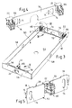
- an inventive device 1 is shown partially fictitious partially transparent; It consists of a can-like receptacle housing 2 (see also in particular the separate illustration in FIG. 3) and a device insert 4 to be inserted into the receptacle housing 2 and to be fastened releasably via retaining means with a front (outer) cover plate 6 (see also FIG ).
- the cover plate 6 is shown in Fig. 1 artificially transparent to allow an insight into internal components.
- the cover plate 6 is preferably made of a non-transparent material, for example of a metal (aluminum or stainless steel).
- the attachment of the device insert 4 in the receiving housing 2 indirectly via the cover plate 6 by the device insert 4 and its components is attached to the inside of the cover plate 6 or are, and by the cover plate 6 via form-fitting addable locking connections , 10, 12 is connectable to the receiving housing 2.
- these snap-in connections 8, 10, 12 are seen to be adjustable in a direction substantially perpendicular to the cover plate 6 (cf., for example, the double arrows 14 in FIGS. 3 to 6) and fixable in different adjustment positions such that the device insert 4 with respect to its inserted and fixed by latching mounting position relative to the receiving housing 2 in the cover plate 6 substantially perpendicular direction is aligned. It can also be compensated level inclinations.
- the receiving housing 2 is designed in particular for flush-mounted installation, wherein it is installed in the installed state shown in FIG. 2 with a certain minimum insertion depth T in a plastered wall mounting surface 16 (to be plastered in).
- the latching connections 8, 10, 12 are designed in such a way that-regardless of the actual depth of insertion T of the receiving housing 2 and any oblique orientation of a housing base surface relative to the mounting surface 16 -the cover plate 6 encloses the base surface of the receiving housing preferably in all directions projecting edge 18 in the inserted and latched state comes to rest on the mounting surface 16 and in particular indirectly via a seal 20.
- the cover plate 6 is very exactly parallel to the mounting surface 16th
- the invention is also suitable for a so-called cavity wall mounting in an analogous manner, wherein the receiving housing 2 is to be inserted into an opening of a cavity wall lining.
- the cover plate 6 has on its inner side facing the device insert 4 at least on a partial area of its edge 18 a strip-shaped seal 20 for sealing contact with the mounting surface 16.
- This seal 20 is made of a soft, elastic material, in particular sponge rubber or the like.
- the snap-in connections 8, 10, 12 on the side of the receiving housing 2 flat, tab-like support elements 22, the housing 2 in parallel to the cover plate 6 and the mounting surface 16 alignment for resting on the adjacent mounting surface 16 to the outside overtop.
- Characterized a defined relation of the locking connections to the mounting surface 16 is provided for the setting, so that a very accurate adjustment of the locking connections relative to the mounting surface 16 is possible, regardless of the actual insertion depth T of the receiving housing. 2
- the snap-in connections 8, 10, 12 are further designed such that the device insert 4 by means of simple insertion into the receiving housing 2 automatically indirectly via the cover plate 6 is positively latched.
- at least one (12) of the latching connections for locking or unlocking means of a special tool 24 ( Figures 10 and 11) between a locking position and a release position movable latch member 26. 10
- the special tool 24 is formed in the example shown in the manner of an open-end wrench and for the purpose of unlocking or locking the locking connection 12 through a slot opening 28 between the cover plate 6 and receiving housing 2 inserted.
- the latch part 26 is preferably rotatable by means of the tool 24 about an axis of rotation 30 perpendicular to the cover plate 6.
- the latch member 26 has two opposite key surfaces 32, and the tool 24 has a correspondingly adapted key mouth 34 with an opening axis 36.
- An actuating section 38 adjoins the region of the key jaw 34, whose longitudinal axis 40 encloses an obtuse angle ⁇ of, in particular, approximately 130 ° to 140 °, preferably approximately 135 °, with the opening axis 36 of the key jaw 34. This angular position facilitates rotation of the latch member 26 by at least 90 °.
- the operating portion 38 of the tool 24 has at its free end on a cranked handle portion 42 that this is spaced in the application of the wall mounting surface 16. This facilitates the gripping of the grip portion by hand and avoids collisions with the wall surface 16.
- the device 1 is preferably formed with a substantially rectangular basic device shape of the receiving housing 2 and the cover plate 6.
- the device 1 is installed so that the cover plate 6 is parallel to the mounting surface 16 in a vertical plane.
- the narrow sides of the rectangular basic form are horizontal and the long sides vertical.
- an upper edge 44 and a lower edge 46 are horizontal and two side edges 48 are vertically aligned.
- the cover plate 6 is provided at the upper edge 44 and at both side edges 48 with the seal 20, while the lower edge 46 in the region of the slot opening 28 for the tool 24 is at least partially seal-free.
- the receiving housing 2 according to FIG. 3 has a correspondingly rectangular receiving space 50 with a bottom 52 and four walls perpendicular thereto, namely an upper wall 54, a lower wall 56 and two side walls 58.
- a third, operable by the tool 24 latching connection 12 are arranged and designed such that the device insert 4 with the cover plate 6, starting from its inserted and positively latched state (Figs. 1 and 2 ) After unlocking the provided at the lower edge 46 latching connection 12 initially only with the lower portion of the cover plate 6 of FIG. 2 in the direction of arrow 60 of the receiving housing 2 movable away and then the whole device insert 4 with the cover plate 6, canceling the positive connection of the upper snap-in connections 8, 10 approximately parallel to the mounting surface 16 in the direction of arrow 62 can be pulled down.
- each latching connection consists of a clamp-like, formed between two resilient locking legs 64 locking receptacle 66 and an insertable into the locking receptacle 66 between the latching leg 64 latch member, either the already mentioned rotatable latch member 26 or a stationary fixed to the cover plate 6 latch member 68th
- Each approximately mushroom-shaped latch member 26, 68 has, according to FIG. 9, undercut surfaces 67, which cooperate with latching edges 69 of the latching limbs 64 (see also FIG. 6) in a form-locking manner during the joining process (see in particular FIG. 8).
- the arranged at the upper edge 44 locking receivers 66 are in this case in the removal direction (arrow 62 in Fig.
- the locking receptacles 66 are arranged correspondingly adjustable in the receiving housing 2, while the latch members 26, 68 are held in the direction perpendicular to the cover plate 6 stationary on the cover plate 6.
- two locking receptacles 66 are preferably fastened to the upper wall 54 of the receiving housing 2 via a common, strip-shaped mounting part 70.
- the mounting member 70 forms with the two locking receptacles 66 a preassembled module, which is shown separately in Fig. 4.
- the locking receptacle 66 is attached centrally via a further strip-shaped mounting member 72 on the lower wall 56 of the receiving housing 2.
- the mounting member 72 forms with the locking receptacle 66 in Fig. 5th separately shown pre-assembled component.
- each mounting part 70, 72 for the inventive adjustability of the locking connections 8, 10, 12 slots 74.
- the attachment is effected by means not shown, the slots 74 by cross and engaging in threaded holes 76 of the receiving housing 2 screws. How z. B. results from Fig. 3 and 6, the described setting in the double arrow 14 is possible through the slots 74.
- the lower mounting part 72 has lateral support portions 78 for the cover plate 6, between which the slot opening 28 is formed for the tool 24; see in particular FIG. 11.
- the receiving housing 2 is plastered in a conventional manner in a wall. This can be done in practice with different insertion depth T and often with an oblique, non-parallel orientation of the bottom 52 relative to the wall mounting surface 16. Subsequently, the locking receptacles 66 are fastened in the receiving housing 2 via the mounting parts 70, 72. In this case, an adjustment is made by the support elements 22 are brought flush to the support on the mounting surface 16 (see Fig. 2). As a result, the latching connections 8, 10, 12 are adjusted exactly to the plane of the mounting surface 16. By simply inserting and locking the device insert 4 with the cover plate 6 an optimal, wall-mounted installation is guaranteed.
- the receiving housing 2 can have two lateral mounting brackets 80 in its lower area to facilitate assembly.
- there are lever-like, fold-out mounting bracket 80 which are pivotally mounted on one of the side walls 58 about an axis 82.
- Each mounting bracket 80 is thereby folded out of a completely in the receiving space 50 of the receiving housing 2 lying non-use position (Figs. 12 and 13) in the double arrow 84 forward and down in a position of use, s. Fig. 14.
- Each mounting bracket has an end receiving slot 86 such that, as shown in FIG. 14, the cover plate 6 with its lower edge portion in the receiving slots 86 of the mounting bracket 80 inserted and thereby fixed in one of the receiving housing 2 forward projecting position.
- the device insert 4 can be used with the cover plate 6 in the manner described above in the receiving housing 2 and locked ,
- the invention also relates to the individual components of the device 1, d. H. on the separate device insert 4 and also on the receiving housing 2 in each case according to the invention adapted design.
- the device 1 according to the invention can in principle also be installed in surface-mounted (AP) mounting by fixing the receiving housing 2 on a mounting surface.
- AP surface-mounted
- the invention has hitherto not been limited to the feature combination defined in claim 1, but may also be defined by any other combination of specific features of all individually disclosed individual features. This means that in principle virtually every individual feature of claim 1 can be omitted or replaced by at least one individual feature disclosed elsewhere in the application. In this respect, the claim 1 is to be understood only as a first formulation attempt for an invention.
Abstract
Description
Die vorliegende Erfindung betrifft ein elektrisches Gerät, insbesondere eine Sprechstation für eine Hauskommunikationsanlage, bestehend aus einem ortsfest zu installierenden, dosenartigen Aufnahmegehäuse und einem in das Aufnahmegehäuse einzusetzenden und über Haltemittel lösbar zu befestigenden Geräteeinsatz mit einer vorderen Deckplatte.The present invention relates to an electrical device, in particular a speaking station for a home communication system, consisting of a stationary to be installed, can-like receptacle housing and a to be inserted into the receptacle and releasably secured by holding means device insert with a front cover plate.
Bei derartigen Geräten wird häufig der Geräteeinsatz über Schraubverbindungen in dem Aufnahmegehäuse befestigt. Dies hat den Nachteil einer relativ umständlichen und zeitaufwendigen Montage. Zudem ist eine Demontage auch durch nicht autorisierte Personen möglich, indem zum Lösen von Schraubverbindungen übliche Werkzeuge verwendbar sind. Es sind auch Geräte bekannt, bei denen der Geräteeinsatz in das dosenartige Aufnahmengehäuse eingerastet werden kann. Dies führt im Falle einer Unterputz-Montage (UP-Installation) bzw. einer Hohlwand-Installation, wobei das Aufnahmegehäuse versenkt in eine Wandfläche eingeputzt oder in eine Hohlwand eingesetzt wird, zu dem Nachteil, dass sich unterschiedliche Einsenktiefen des Aufnahmegehäuses auch in unterschiedlichen Positionen des Geräteeinsatzes relativ zu der Montage-Bezugsebene (Wandfläche) auswirken.In such devices, the device insert is often attached via screw in the receiving housing. This has the disadvantage of a relatively complicated and time-consuming installation. In addition, disassembly by unauthorized persons is possible by usual tools are used to loosen screw. There are also known devices in which the device insert can be snapped into the can-like receptacle housing. This leads in the case of a flush-mounting (UP installation) or a cavity wall installation, the receiving housing sunk flushed into a wall surface or inserted into a cavity wall, to the disadvantage that different insertion depths of the receiving housing in different positions of Equipment use relative to the mounting reference plane (wall surface).
Der vorliegenden Erfindung liegt die Aufgabe zugrunde, ein Gerät der beschriebenen Art zu schaffen, bei dem der Geräteeinsatz auf schnelle und einfache Weise sowie auch mit einer hohen Sicherheit gegen nicht autorisiertes Lösen und mit einer exakten Ausrichtung relativ zu einer Montage-Bezugsebene in dem Aufnahmegehäuse befestigbar ist.The present invention has for its object to provide a device of the type described, in which the device insert in a fast and easy way and also with a high security against unauthorized release and with a precise alignment relative to a mounting reference plane in the receiving housing fastened is.
Erfindungsgemäß wird dies durch die Merkmale des Anspruchs 1 erreicht. Vorteilhafte Ausgestaltungen der Erfindung sind Gegenstand der abhängigen Ansprüche.This is achieved by the features of
Demnach sind die Haltemittel als formschlüssig fügbare Rastverbindungen ausgebildet, wodurch eine einfache und schnelle Montage durch einfaches Einsetzen des Geräteeinsatzes in das Aufnahmegehäuse erreicht wird. Dabei ist der Geräteeinsatz selbsttätig formschlüssig einrastbar. Zudem wird durch den Formschluss eine hohe Sicherheit gegen unberechtigtes Lösen erreicht. Für ein autorisiertes Lösen ist bevorzugt vorgesehen, dass mindestens eine der Rastverbindungen ein zum Verriegeln bzw. Entriegeln mittels eines speziellen Werkzeuges zwischen einer Verriegelungsstellung und einer Lösestellung bewegbares Riegelteil aufweist. Somit ist ein Lösen nicht ohne das spezielle Werkzeug möglich.Accordingly, the holding means are formed as a form-fitting addable locking connections, whereby a simple and quick installation is achieved by simply inserting the device insert into the receiving housing. The device insert is automatically positively locked. In addition, a high level of security against unauthorized release is achieved by the positive locking. For an authorized release, it is preferably provided that at least one of the latching connections has a latch part which is movable between a latching position and a release position for locking or unlocking by means of a special tool. Thus, a release is not possible without the special tool.
Weiterhin sind die Rastverbindungen erfindungsgemäß in einer zu der Deckplatte im Wesentlichen senkrechten Richtung gesehen derart verstellbar und in unterschiedlichen Einstellpositionen fixierbar, dass der Geräteeinsatz bzgl. seiner eingesetzten und verrasteten Einbaustellung relativ zu dem Aufnahmegehäuse in der zu der Deckplatte im Wesentlichen senkrechten Richtung ausrichtbar ist. Durch diese Ausrichtung relativ zu dem Aufnahmegehäuse ist folglich auch eine Ausrichtung des Geräteeinsatzes relativ zu der jeweiligen auf die ortsfeste Befestigung des Aufnahmegehäuses bezogenen Montage-Bezugsebene möglich. So ist in bevorzugter Ausgestaltung das Aufnahmegehäuse zur Unterputz-(bzw. Hohlwand-) Installation konzipiert, wobei es in einem installierten Zustand mit einer bestimmten Mindest-Einsenktiefe versenkt in einer Wand-Montagefläche anzuordnen ist. Hierbei sind nun die Rastverbindungen derart einstellbar, dass - unabhängig von der jeweiligen Einsenktiefe des Aufnahmegehäuses gegenüber der Montagefläche - die Deckplatte mit einem die Grundfläche des Aufnahmegehäuses überragenden Rand im eingesetzten und verrasteten Zustand des Geräteeinsatzes zur definierten Anlage auf der umliegenden Montagefläche gelangt, und zwar insbesondere mittelbar über eine Dichtung. Für diese Einstellbarkeit ist es vorteilhaft, wenn die Rastverbindungen auf der Seite des Aufnahmegehäuses letzteres nach außen überragende Auflagelaschen zur Auflage auf der Montagefläche aufweisen. Dadurch wird ein definierter Bezug der Rastverbindungen zur Montagefläche erreicht, so dass eine sehr exakte und auch einfach und schnell durchführbare Einstellung relativ zur Montagefläche möglich ist, und zwar unabhängig von unterschiedlichen Einsenktiefen des Aufnahmegehäuses.Furthermore, the snap-in connections according to the invention are seen to be adjustable and fixable in different adjustment positions in a direction substantially perpendicular to the cover plate so that the device insert is alignable with respect to its inserted and latched mounting position in the direction substantially perpendicular to the cover plate. As a result of this orientation relative to the receiving housing, alignment of the appliance insert relative to the respective mounting reference plane relative to the stationary attachment of the receiving housing is consequently also possible. Thus, in a preferred embodiment, the receiving housing is designed for concealed (or cavity wall) installation, wherein it is to be arranged in an installed state with a certain minimum insertion depth sunk in a wall mounting surface. Here, the snap-in connections are adjustable so that - regardless of the respective insertion depth of the receiving housing relative to the mounting surface - the cover plate with a the base of the receiving housing superior edge in the inserted and locked state of the device insert reaches the defined installation on the surrounding mounting surface, in particular indirectly via a seal. For this adjustability, it is advantageous if the latching connections on the side of the receiving housing have the latter outwardly projecting support tabs for resting on the mounting surface. As a result, a defined relation of the latching connections to the mounting surface is achieved, so that a very exact and also easy and quickly feasible adjustment relative to the mounting surface is possible, regardless of different insertion depths of the receiving housing.
Weitere vorteilhafte Ausgestaltungsmerkmale der Erfindung werden auch in der folgenden Beschreibung noch erläutert werden.Further advantageous features of the invention will also be explained in the following description.
Anhand eines in Zeichnung veranschaulichten, bevorzugten Ausführungsbeispiels soll die Erfindung genauer erläutert werden. Dabei zeigen:
- Fig. 1
- eine Perspektivansicht eines erfindungsgemäßen Gerätes in einem noch nicht installierten, aber zusammengefügten Zustand seiner Teile,
- Fig. 2
- einen Schnitt in einer vertikalen Schnittebene II - II gemäß Fig. 1 im installierten Zustand, und zwar in Unterputz-Installation,
- Fig. 3
- eine Perspektivansicht nur des Aufnahmegehäuses,
- Fig. 4
- eine Perspektivansicht eines Einzelteils mit Bestandteilen zweier erfindungsgemäßer Rastverbindungen,
- Fig. 5
- eine Perspektivansicht eines weiteren Einzelteils mit einem Bestandteil einer der Rastverbindungen,
- Fig. 6
- eine vergrößerte Teilansicht des Bereichs VI in Fig. 3,
- Fig. 7
- eine perspektivische Ansicht der Deckplatte des Geräteeinsatzes, und zwar auf deren Geräte-Innenseite,
- Fig.8
- eine Ansicht ähnlich Fig. 6 mit zusätzlichen Bestandteilen, die eigentlich an der Deckplatte angeordnet sind,
- Fig. 9
- einen vergrößerten Teilschnitt in der Ebene IX- IX gemäß Fig. 1,
- Fig. 10
- eine Teil-Perspektivansicht auf die Oberseite des Aufnahmegehäuses zur Erläuterung des Lösevorgangs,
- Fig.11
- eine Ansicht ähnlich Fig. 10 auf die Unterseite des Aufnahmegehäuses,
- Fig. 12
- eine perspektivische Schnittansicht in einer vertikalen Schnittebene im unteren Bereich des Gerätes in einer vorteilhaften Ausgestaltung, und zwar mit zusätzlichen Montagehaltern,
- Fig. 13
- eine perspektivische Teil-Explosionsansicht des Aufnahmegehäuses nach Fig. 12 und
- Fig.14
- eine Teil-Perspektivansicht des Aufnahmegehäuses in einer Montagestellung mit über die Montagehalter fixierter Deckplatte.
- Fig. 1
- a perspective view of a device according to the invention in a not yet installed, but assembled state of its parts,
- Fig. 2
- 1 in the installed state, in flush installation,
- Fig. 3
- a perspective view only of the receiving housing,
- Fig. 4
- a perspective view of an item with components of two inventive snap-in connections,
- Fig. 5
- a perspective view of another item with a part of one of the locking connections,
- Fig. 6
- an enlarged partial view of the area VI in Fig. 3,
- Fig. 7
- a perspective view of the cover plate of the device insert, on the inside of the device,
- Figure 8
- 6 is a view similar to FIG. 6 with additional components that are actually arranged on the cover plate;
- Fig. 9
- an enlarged partial section in the plane IX-IX of FIG. 1,
- Fig. 10
- a partial perspective view of the top of the receiving housing to explain the dissolution process,
- Figure 11
- a view similar to FIG. 10 on the underside of the receiving housing,
- Fig. 12
- a perspective sectional view in a vertical sectional plane in the lower region of the device in an advantageous embodiment, with additional mounting brackets,
- Fig. 13
- a partial perspective exploded view of the receiving housing of FIG. 12 and
- Figure 14
- a partial perspective view of the receiving housing in a mounting position with fixed via the mounting bracket cover plate.
In den verschiedenen Figuren der Zeichnung sind gleiche Teile stets mit den gleichen Bezugszeichen versehen.In the various figures of the drawing, like parts are always provided with the same reference numerals.
In Fig. 1 ist ein erfindungsgemäßes Gerät 1 fiktiv teiltransparent dargestellt; es besteht aus einem dosenartigen Aufnahmegehäuse 2 (siehe auch insbesondere die gesonderte Darstellung in Fig. 3) und einem in das Aufnahmegehäuse 2 einzusetzenden und über Haltemittel lösbar zu befestigenden Geräteeinsatz 4 mit einer vorderen (äußeren) Deckplatte 6 (vgl. hierzu auch Fig. 7). Die Deckplatte 6 ist in Fig. 1 künstlich transparent dargestellt, um eine Einsicht auf innere Bestandteile zu gewähren. In der Realität besteht die Deckplatte 6 bevorzugt aus einem nicht transparenten Material, beispielsweise aus einem Metall (Aluminium oder Edelstahl).In Fig. 1, an
In der bevorzugten Ausführung erfolgt die Befestigung des Geräteeinsatzes 4 in dem Aufnahmegehäuse 2 mittelbar über die Deckplatte 6, indem der Geräteeinsatz 4 bzw. dessen Bestandteile an der Innenseite der Deckplatte 6 befestigt ist bzw. sind, und indem die Deckplatte 6 über formschlüssig fügbare Rastverbindungen 8, 10, 12 mit dem Aufnahmegehäuse 2 verbindbar ist.In the preferred embodiment, the attachment of the
Erfindungsgemäß sind diese Rastverbindungen 8, 10, 12 in einer zu der Deckplatte 6 im Wesentlichen senkrechten Richtung gesehen (vgl. hierzu die Doppelpfeile 14 z. B. in Fig. 3 bis 6) derart verstellbar und in unterschiedlichen Einstellpositionen fixierbar ausgebildet, dass der Geräteinsatz 4 mit der Deckplatte 6 bzgl. seiner eingesetzten und durch Verrastung befestigten Einbaustellung relativ zu dem Aufnahmegehäuse 2 in der zur Deckplatte 6 im Wesentlichen senkrechten Richtung ausrichtbar ist. Dabei können auch Ebenen-Schrägstellungen ausgeglichen werden.According to the invention, these snap-in
Gemäß Fig. 2 ist das Aufnahmegehäuse 2 insbesondere zur Unterputz-Installation konzipiert, wobei es in dem in Fig. 2 dargestellten, installierten Zustand mit einer bestimmten Mindest-Einsenktiefe T versenkt in einer verputzten Wand-Montagefläche 16 anzuordnen (einzuputzen) ist. Dabei sind die Rastverbindungen 8, 10, 12 bzgl. ihrer Einstellbarkeit derart ausgebildet, dass - unabhängig von der jeweiligen tatsächlichen Einsenktiefe T des Aufnahmegehäuses 2 und einer eventuellen Schrägausrichtung einer Gehäuse-Grundfläche gegenüber der Montagefläche 16 - die Deckplatte 6 mit einem die Grundfläche des Aufnahmegehäuses bevorzugt in allen Richtungen überragenden Rand 18 im eingesetzten und verrasteten Zustand zur Anlage auf der Montagefläche 16 gelangt und zwar insbesondere mittelbar über eine Dichtung 20. Damit liegt die Deckplatte 6 sehr exakt parallel auf der Montagefläche 16.According to FIG. 2, the receiving
An dieser Stelle sei nochmals bemerkt, dass die Erfindung in analoger Weise auch für eine sogenannte Hohlwand-Montage geeignet ist, wobei das Aufnahmegehäuse 2 in eine Öffnung einer Hohlwand-Verkleidung einzusetzen ist.It should again be noted that the invention is also suitable for a so-called cavity wall mounting in an analogous manner, wherein the receiving
Wie sich insbesondere aus Fig. 7 ergibt, weist die Deckplatte 6 auf ihrer dem Geräteeinsatz 4 zugewandten Innenseite zumindest auf einem Teilbereich ihres Randes 18 eine streifenförmige Dichtung 20 zur dichtenden Anlage auf der Montagefläche 16 auf. Diese Dichtung 20 besteht aus einem weichen, elastischen Material, wie insbesondere Moosgummi oder dergleichen.As can be seen in particular from FIG. 7, the
Für ihre erfindungsgemäße Einstellbarkeit weisen die Rastverbindungen 8, 10, 12 auf der Seite des Aufnahmegehäuses 2 flache, laschenartige Auflageelemente 22 auf, die das Aufnahmegehäuse 2 in einer zur Deckplatte 6 bzw. zur Montagefläche 16 parallelen Ausrichtung zur Auflage auf der angrenzenden Montagefläche 16 nach außen überragen. Dadurch wird für die Einstellung ein definierter Bezug der Rastverbindungen zur Montagefläche 16 geschaffen, so dass eine sehr genaue Einstellung der Rastverbindungen relativ zur Montagefläche 16 möglich ist, und zwar unabhängig von der tatsächlichen Einsenktiefe T des Aufnahmegehäuses 2.For their adjustability according to the invention, the snap-in
Die Rastverbindungen 8, 10, 12 sind weiterhin derart ausgebildet, dass der Geräteeinsatz 4 durch einfaches Einsetzen in das Aufnahmegehäuse 2 selbsttätig mittelbar über die Deckplatte 6 formschlüssig verrastbar ist. Dabei weist mindestens eine (12) der Rastverbindungen ein zum Verriegeln bzw. Entriegeln mittels eines speziellen Werkzeuges 24 (Fig. 10 und 11) zwischen einer Verriegelungsstellung und einer Lösestellung bewegbares Riegelteil 26 auf. Gemäß Fig. 10 ist das SpezialWerkzeug 24 im dargestellten Beispiel nach Art eines Maulschlüssels ausgebildet und zwecks Entriegeln oder Verriegeln der Rastverbindung 12 durch eine Schlitzöffnung 28 zwischen Deckplatte 6 und Aufnahmegehäuse 2 einführbar. Dabei ist das Riegelteil 26 bevorzugt mittels des Werkzeugs 24 um eine zur Deckplatte 6 senkrechte Drehachse 30 verdrehbar. Das Riegelteil 26 weist zwei gegenüberliegende Schlüsselflächen 32 auf, und das Werkzeug 24 weist ein entsprechend angepaßtes Schlüsselmaul 34 mit einer Öffnungsachse 36 auf. An den Bereich des Schlüsselmauls 34 schließt sich ein Betätigungsabschnitt 38 an, dessen Längsachse 40 mit der Öffnungsachse 36 des Schlüsselmauls 34 einen stumpfen Winkel α von insbesondere etwa 130° bis 140°, vorzugsweise etwa 135°, einschließt. Diese Winkelstellung vereinfacht eine Drehung des Riegelteils 26 um jeweils mindestens 90°. Der Betätigungsabschnitt 38 des Werkzeugs 24 weist an seinem freien Ende einen derart verkröpften Griffabschnitt 42 auf, dass dieser bei der Anwendung von der Wand-Montagefläche 16 beabstandet ist. Dies erleichtert das Ergreifen des Griffabschnittes mit der Hand und vermeidet Kollisionen mit der Wandfläche 16.The snap-in
Wie sich insbesondere aus Fig. 1 ergibt, ist das Gerät 1 bevorzugt mit einer im Wesentlichen rechteckigen Gerätegrundform des Aufnahmegehäuses 2 und der Deckplatte 6 ausgebildet. In einer bestimmungsgemäßen Montageanordnung wird das Gerät 1 so installiert, dass die Deckplatte 6 in einer vertikalen Ebene parallel zur Montagefläche 16 liegt. Die Schmalseiten der rechteckigen Grundform verlaufen horizontal und die Längsseiten vertikal. Somit sind ein oberer Rand 44 und ein unterer Rand 46 horizontal sowie zwei Seitenränder 48 vertikal auszurichten. Gemäß Fig. 1 und 7 ist die Deckplatte 6 am oberen Rand 44 und an beiden Seitenrändern 48 mit der Dichtung 20 versehen, während der untere Rand 46 im Bereich der Schlitzöffnung 28 für das Werkzeug 24 zumindest teilweise dichtungsfrei ist. Bei der bevorzugten Geräte-Grundform weist das Aufnahmegehäuse 2 gemäß Fig. 3 einen entsprechend rechteckigen Aufnahmeraum 50 mit einem Boden 52 und vier dazu senkrechten Wänden auf, und zwar einer oberen Wand 54, einer unteren Wand 56 und zwei Seitenwänden 58.As is apparent in particular from FIG. 1, the
Bei der dargestellten, bevorzugten Ausführung des Gerätes 1 ist weiterhin vorgesehen, dass im Bereich des oberen Randes 44 zwei seitlich beabstandete Rastverbindungen 8, 10 und im mittigen Bereich des unteren Randes 46 eine dritte, mittels des Werkzeugs 24 betätigbare Rastverbindung 12 derart angeordnet und ausgebildet sind, dass der Geräteeinsatz 4 mit der Deckplatte 6 ausgehend von seinem eingesetzten und formschlüssig verrasteten Zustand (Fig. 1 und 2) nach Entriegeln der am unteren Rand 46 vorgesehenen Rastverbindung 12 zunächst nur mit dem unteren Bereich der Deckplatte 6 gemäß Fig. 2 in Pfeilrichtung 60 von dem Aufnahmegehäuse 2 weg bewegbar und anschließend der ganze Geräteeinsatz 4 mit der Deckplatte 6 unter Aufhebung des Formschlusses der oberen Rastverbindungen 8, 10 etwa parallel zur Montagefläche 16 in Pfeilrichtung 62 nach unten herausziehbar ist. Dazu besteht jede Rastverbindung aus einer klammerartigen, zwischen zwei federelastischen Rastschenkeln 64 gebildeten Rastaufnahme 66 und einem in die Rastaufnahme 66 zwischen die Rastschenkel 64 einsetzbaren Riegelteil, und zwar entweder dem bereits erwähnten drehbaren Riegelteil 26 oder einem ortsfest an der Deckplatte 6 befestigten Riegelteil 68. Jedes etwa pilzförmige Riegelteil 26, 68 weist gemäß Fig. 9 Hinterschneidungsflächen 67 auf, die beim Fügevorgang mit Rastkanten 69 der Rastschenkel 64 (siehe dazu auch Fig. 6) formschlüssig rastend zusammenwirken (siehe insbesondere Fig. 8). Die am oberen Rand 44 angeordneten Rastaufnahmen 66 sind hierbei in Entnahmerichtung (Pfeil 62 in Fig. 2) vertikal nach unten offen, so dass die Riegelteile 68 in dieser Richtung (siehe auch die Pfeile Z in Fig. 9) unter Aufhebung des Formschlusses herausgezogen werden können. Die Riegelteile 26, 68 weisen weiterhin vordere, z. B. konische Einführschrägflächen 71 auf, die beim Einführen die Rastschenkel 64 elastisch spreizen.In the illustrated, preferred embodiment of the
Für die erfindungsgemäße Einstellbarkeit sind vorzugsweise die Rastaufnahmen 66 entsprechend verstellbar in dem Aufnahmegehäuse 2 angeordnet, während die Riegelteile 26, 68 in der zur Deckplatte 6 senkrechten Richtung ortsfest an der Deckplatte 6 gehalten sind.For the adjustability according to the invention preferably the locking
Im Bereich des oberen Randes 44 sind vorzugsweise zwei Rastaufnahmen 66 über ein gemeinsames, streifenförmiges Montageteil 70 an der oberen Wand 54 des Aufnahmegehäuses 2 befestigt. Somit bildet das Montageteil 70 mit den zwei Rastaufnahmen 66 eine vormontierte Baugruppe, die in Fig. 4 gesondert dargestellt ist. Am unteren Rand 46 ist die Rastaufnahme 66 mittig über ein weiteres streifenförmiges Montageteil 72 an der unteren Wand 56 des Aufnahmegehäuses 2 befestigt. Hier bildet das Montageteil 72 mit der Rastaufnahme 66 das in Fig. 5 gesondert dargestellte vormontierte Bauteil. Dabei weist jedes Montageteil 70, 72 für die erfindungsgemäße Einstellbarkeit der Rastverbindungen 8, 10, 12 Langlöcher 74 auf. Die Befestigung erfolgt mittels nicht dargestellter, die Langlöcher 74 durchgreifender und in Gewindelöcher 76 des Aufnahmegehäuses 2 eingreifender Schrauben. Wie sich z. B. aus Fig. 3 und 6 ergibt, ist durch die Langlöcher 74 die beschriebene Einstellung in Doppelpfeilrichtung 14 möglich.In the region of the
Das untere Montageteil 72 weist seitliche Auflageabschnitte 78 für die Deckplatte 6 auf, zwischen denen die Schlitzöffnung 28 für das Werkzeug 24 gebildet ist; siehe hierzu insbesondere Fig. 11.The lower mounting
Abschließend soll noch kurz die Montage des Gerätes 1 erläutert werden. Dazu wird zunächst das Aufnahmegehäuse 2 in üblicher Weise in eine Wand eingeputzt. Dies kann in der Praxis mit unterschiedlicher Einsenktiefe T und häufig auch mit einer schrägen, nicht parallelen Ausrichtung des Bodens 52 relativ zur Wand-Montagefläche 16 erfolgen. Anschließend werden die Rastaufnahmen 66 über die Montageteile 70, 72 in dem Aufnahmegehäuse 2 befestigt. Dabei erfolgt eine Einstellung, indem die Auflageelemente 22 bündig zur Auflage auf der Montagefläche 16 gebracht werden (vgl. Fig. 2). Dadurch sind die Rastverbindungen 8, 10, 12 genau auf die Ebene der Montagefläche 16 justiert. Durch einfaches Einsetzen und Verrasten des Geräteeinsatzes 4 mit der Deckplatte 6 ist eine optimale, wandaufliegende Montage gewährleistet.Finally, the assembly of the
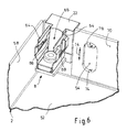
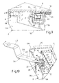
Wie sich noch aus Fig. 12 bis 14 ergibt, kann das Aufnahmegehäuse 2 zur Erleichterung der Montage in seinem unteren Bereich zwei seitliche Montagehalter 80 aufweisen. Vorzugsweise handelt es sich um hebelartige, ausklappbare Montagehalter 80, die an jeweils einer der Seitenwände 58 um eine Achse 82 schwenkbar befestigt sind. Jeder Montagehalter 80 ist dadurch aus einer vollständig innerhalb des Aufnahmeraumes 50 des Aufnahmegehäuses 2 liegenden Nichtgebrauchsstellung (Fig. 12 und 13) in Doppelpfeilrichtung 84 nach vorne und unten in eine Gebrauchsstellung herausklappbar, s. Fig. 14. Jeder Montagehalter weist endseitig einen Aufnahmeschlitz 86 derart auf, dass gemäß Fig. 14 die Deckplatte 6 mit ihrem unteren Randbereich in die Aufnahmeschlitze 86 der Montagehalter 80 einschiebbar und hierdurch in einer von dem Aufnahmegehäuse 2 nach vorne vorstehenden Lage fixierbar ist. In dieser Montagelage sind die Innenseite der Deckplatte 6 und der Aufnahmeraum 50 des Aufnahmegehäuses 2 frei zugänglich, was die Installation, beispielsweise eine Verdrahtung, wesentlich vereinfacht. Nach der Installation (Verdrahtung) braucht nur noch die Deckplatte 6 aus den Aufnahmeschlitzen 86 der Montagehalter 80 herausgezogen zu werden, und nach Einklappen der Montagehalter 80 kann der Geräteeinsatz 4 mit der Deckplatte 6 in der oben beschriebenen Weise in das Aufnahmegehäuse 2 eingesetzt und verrastet werden.As can be seen from FIGS. 12 to 14, the receiving
Die Erfindung bezieht sich auch auf die Einzelkomponenten des Gerätes 1, d. h. auf den separaten Geräteeinsatz 4 und auch auf das Aufnahmegehäuse 2 in jeweils erfindungsgemäß angepaßter Ausgestaltung.The invention also relates to the individual components of the
Die Erfindung ist nicht auf die dargestellten und beschriebenen Ausführungsbeispiele beschränkt, sondern umfasst auch alle im Sinne der Erfindung gleichwirkenden Ausführungen. So kann das erfindungsgemäße Gerät 1 grundsätzlich auch in Aufputz(AP)- Montage installiert werden, indem das Aufnahmegehäuse 2 auf einer Montagefläche befestigt wird. Ferner ist die Erfindung bislang auch noch nicht auf die im Anspruch 1 definierte Merkmalskombination beschränkt, sondern kann auch durch jede beliebige andere Kombination von bestimmten Merkmalen aller insgesamt offenbarten Einzelmerkmalen definiert sein. Dies bedeutet, dass grundsätzlich praktisch jedes Einzelmerkmal des Anspruchs 1 weggelassen bzw. durch mindestens ein an anderer Stelle der Anmeldung offenbartes Einzelmerkmal ersetzt werden kann. Insofern ist der Anspruch 1 lediglich als ein erster Formulierungsversuch für eine Erfindung zu verstehen.The invention is not limited to the illustrated and described embodiments, but also includes all the same in the context of the invention embodiments. Thus, the
Claims (17)
dadurch gekennzeichnet, dass die Haltemittel als formschlüssig fügbare Rastverbindungen (8, 10, 12) ausgebildet sind, die in einer zu der Deckplatte (6) im Wesentlichen senkrechten Richtung gesehen derart verstellbar und in unterschiedlichen Einstellpositionen fixierbar sind, dass der Geräteeinsatz (4) mit der Deckplatte (6) bezüglich seiner eingesetzten und befestigten Einbaustellung relativ zu dem Aufnahmegehäuse (2) in der zu der Deckplatte (6) im Wesentlichen senkrechten Richtung ausrichtbar ist.Electrical device (1), in particular a speaking station for a home communication system, consisting of a receptacle housing (2) to be installed in a stationary manner and a device insert (4) to be inserted in the receptacle housing (2) and detachably fastened by holding means, with a front cover plate (6) .
characterized in that the holding means are formed as form-fitting addable locking connections (8, 10, 12) seen in a direction to the cover plate (6) substantially vertical direction are adjustable and fixable in different setting positions, that the device insert (4) the cover plate (6) with respect to its inserted and fixed installation position relative to the receiving housing (2) in the direction of the cover plate (6) is substantially perpendicular direction aligned.
dadurch gekennzeichnet, dass das Aufnahmegehäuse (2) zur Unterputz-Installation konzipiert ist, wobei es in einem installierten Zustand mit einer Einsenktiefe (T) versenkt in einer Wand-Montagefäche (16) anzuordnen ist, wobei die Rastverbindungen (8, 10, 12) derart einstellbar sind, dass - unabhängig von der jeweiligen Einsenktiefe (T) des Aufnahmegehäuses (2) gegenüber der Montagefläche (16) - die Deckplatte (6) mit einem das Aufnahmegehäuse (2) überragenden Rand (18) im eingesetzten und verrasteten Zustand des Geräteeinsatzes (4) zur Auflage auf der Montagefläche (16) gelangt, und zwar insbesondere mittelbar über eine Dichtung (20).Apparatus according to claim 1,
characterized in that the receiving housing (2) is designed for flush installation, wherein it is to be arranged sunk in an installed state with a sinking depth (T) in a Wand-Montagefäche (16), wherein the latching connections (8, 10, 12) are adjustable so that - regardless of the respective insertion depth (T) of the receiving housing (2) relative to the mounting surface (16) - the cover plate (6) with a receiving housing (2) superior edge (18) in the inserted and locked state of the device insert (4) comes to rest on the mounting surface (16), in particular indirectly via a seal (20).
dadurch gekennzeichnet, dass die Deckplatte (6) zumindest auf einem Teilbereich ihres Randes (18) eine streifenförmige Dichtung (20) zur dichtenden Anlage auf der Montagefläche (16) aufweist, wobei die Dichtung (20) aus einem weichen, elastischen Material, wie Moosgummi oder dergleichen, besteht.Apparatus according to claim 2,
characterized in that the cover plate (6) at least on a portion of its edge (18) has a strip-shaped seal (20) for sealing engagement on the mounting surface (16), wherein the seal (20) made of a soft, elastic material, such as sponge rubber or the like.
dadurch gekennzeichnet, dass die Rastverbindungen (8,10, 12) für die Einstellbarkeit auf der Seite des Aufnahmegehäuses (2) letzteres nach außen überragende Auflageelemente (22) zur Auflage auf der angrenzenden Montagefläche (16) aufweisen.Apparatus according to claim 2 or 3,
characterized in that the latching connections (8,10, 12) for the adjustability on the side of the receiving housing (2) the latter outwardly superior support elements (22) for resting on the adjacent mounting surface (16).
dadurch gekennzeichnet, dass die Rastverbindungen (8,10, 12) derart ausgebildet sind, dass der Geräteeinsatz (4) durch Einsetzen in das Aufnahmegehäuse (2) selbsttätig formschlüssig einrastbar ist, wobei mindestens eine (12) der Rastverbindungen (8, 10, 12) ein zum Verriegeln bzw. Entriegeln mittels eines speziellen Werkzeuges (24) zwischen einer Verriegelungsstellung und einer Lösestellung bewegbares Riegelteil (26) aufweist.Device in particular according to one of claims 1 to 4,
characterized in that the latching connections (8,10, 12) are formed such that the device insert (4) by insertion into the receiving housing (2) is automatically positively latched, wherein at least one (12) of the latching connections (8, 10, 12 Has a for locking or unlocking by means of a special tool (24) between a locking position and a release position movable latch member (26).
dadurch gekennzeichnet, dass dasinsbesonderenachArt eines Maulschlüssels ausgebildete Werkzeug (24) zwecks Entriegeln oder Verriegeln der Rastverbindung (12) durch eine Schlitzöffnung (28) zwischen Deckplatte (6) und Aufnahmegehäuse (2) einführbar ist.Apparatus according to claim 5,
characterized in that the tool (24) designed in particular by means of an open-end wrench is insertable through a slot opening (28) between the cover plate (6) and the receptacle housing (2) in order to unlock or lock the detent connection (12).
gekennzeichnet durch eine im Wesentlichen rechteckige Geräte-Grundform des Aufnahmegehäuses (2) und der Deckplatte (6), wobei in einer bestimmungsgemäßen Montageanordnung die Deckplatte (6) in einer vertikalen Ebene, ein oberer Rand (44) und ein unterer Rand (46) horizontal sowie zwei Seitenränder (48) vertikal auszurichten sind, und wobei die Deckplatte (6) am oberen Rand (44) und an den beiden Seitenrändern (48) mit der Dichtung (20) versehen ist, während der untere Rand (46) zur Bildung bzw. Freilassung der Schlitzöffnung (28) für das Werkzeug (24) zumindest teilweise dichtungsfrei ist.Device in particular according to one of claims 4 to 6,
characterized by a substantially rectangular basic device shape of the receiving housing (2) and the cover plate (6), wherein in a proper mounting arrangement, the cover plate (6) in a vertical plane, an upper edge (44) and a lower edge (46) horizontally and two side edges (48) are to be aligned vertically, and wherein the cover plate (6) at the upper edge (44) and at the two side edges (48) with the seal (20) is provided, while the lower edge (46) for forming or Release of the slot opening (28) for the tool (24) is at least partially free of seal.
dadurch gekennzeichnet, dass im Bereich des oberen Randes (44) zwei seitliche Rastverbindungen (8, 10) und im mittigen Bereich des unteren Randes (46) eine mittels des Werkzeugs (24) betätigbare dritte Rastverbindung (12) derart angeordnet und ausgebildet sind, dass der Geräteeinsatz (4) ausgehend von seinem eingesetzten und formschlüssig verrasteten Zustand nach Entriegeln der am unteren Rand (46) vorgesehenen Rastverbindung (12) zunächst mit dem unteren Bereich der Deckplatte (6) von dem Aufnahmegehäuse (2) weg bewegbar und anschließend der ganze Geräteinsatz (4) unter Aufhebung des Formschlusses der oberen Rastverbindungen (8, 10) etwa parallel zur Montagefläche (16) nach unten herausziehbar ist.Device in particular according to claim 7,
characterized in that in the region of the upper edge (44) has two lateral latching connections (8, 10) and in the central region of the lower edge (46) by means of the tool (24) operable third Locking connection (12) are arranged and designed such that the device insert (4) starting from its inserted and positively latched state after unlocking at the lower edge (46) locking connection (12) initially with the lower portion of the cover plate (6) of the Recording housing (2) movable away and then the whole device insert (4) with the repeal of the positive connection of the upper snap-in connections (8, 10) approximately parallel to the mounting surface (16) is pulled down.
dadurch gekennzeichnet, dass jede Rastverbindung (8, 10, 12) aus einer zwischen zwei federelastischen Rastschenkeln (64) gebildeten Rastaufnahme (66) und einem in die Rastaufnahme (66) einsetzbaren Riegelteil (26, 68) besteht, wobei vorzugsweise die Rastaufnahmen (66) verstellbar in dem Aufnahmegehäuse (2) und die Riegelteile (26, 68) an der Deckplatte (6) angeordnet sind.Device according to one of claims 1 to 8,
characterized in that each latching connection (8, 10, 12) consists of a latching receptacle (66) formed between two resilient latching limbs (64) and a locking part (26, 68) insertable into the latching receptacle (66), wherein preferably the latching receptacles (66 ) are adjustably arranged in the receiving housing (2) and the locking parts (26, 68) on the cover plate (6).
dadurch gekennzeichnet, dass am oberen Rand (44) zwei Rastaufnahmen (66) über ein gemeinsames, streifenförmiges Montageteil (70) an dem Aufnahmegehäuse (2) befestigt sind.Apparatus according to claim 9,
characterized in that at the upper edge (44) has two locking receptacles (66) via a common, strip-shaped mounting member (70) on the receiving housing (2) are attached.
dadurch gekennzeichnet, dass am unteren Rand (46) eine mittige Rastaufnahme (66) über ein streifenförmiges Montageteil (72) an dem Aufnahmegehäuse (2) befestigt ist.Apparatus according to claim 9 or 10,
characterized in that at the lower edge (46) has a central locking receptacle (66) via a strip-shaped mounting member (72) on the receiving housing (2) is attached.
dadurch gekennzeichnet, dass das/jedesMontageteil(70, 72) für die Einstellbarkeit der Rastverbindungen (8, 10, 12) Langlöcher (74) aufweist, wobei die Befestigung mittels die Langlöcher (74) durchgreifender und in Gewindelöcher (76) des Aufnahmegehäuses (2) eingreifender Schrauben erfolgt.Apparatus according to claim 10 or 11,
characterized in that the / each mounting portion (70, 72) for the adjustability of the snap-in connections (8, 10, 12) slots (74), said fastening by means of the elongated holes (74) and in threaded holes (76) of the receiving housing (2 ) engaging screws takes place.
dadurch gekennzeichnet, dass die den oberen zwei Rastaufnahmen (66) zugeordneten Riegelteile (68) starr an der Deckplatte (6) befestigt sind.Device according to one of claims 10 to 12,
characterized in that the upper two locking receptacles (66) associated latch members (68) are rigidly secured to the cover plate (6).
dadurch gekennzeichnet, dass das der unteren Rastaufnahme (66) zugeordnete Riegelteil (26) - mittels des Werkzeugs (24) durch die Schlitzöffnung (28) hindurch - drehbar an der Deckplatte (6) gelagert ist.Device according to one of claims 11 to 13,
characterized in that the lower latching receptacle (66) associated latch member (26) - by means of the tool (24) through the slot opening (28) through - rotatably mounted on the cover plate (6).
dadurch gekennzeichnet, dass das Aufnahmegehäuse (2) in seinem - bezogen auf eine bestimmungsgemäß installierte Montagelage - unteren Bereich Montagehalter (80) derart aufweist, dass der Geräteeinsatz (4) mit der Deckplatte (6) über die Montagehalter (80) vorübergehend in einer geöffneten Montagelage an dem Aufnahmegehäuse (2) fixierbar ist.Device according to one of claims 1 to 14,
characterized in that the receiving housing (2) in its - relative to a properly installed mounting position - lower portion mounting bracket (80) such that the device insert (4) with the cover plate (6) via the mounting bracket (80) temporarily in an open Mounting position on the receiving housing (2) is fixable.
Applications Claiming Priority (1)
| Application Number | Priority Date | Filing Date | Title |
|---|---|---|---|
| DE202006005366U DE202006005366U1 (en) | 2006-04-04 | 2006-04-04 | Intercom station for a house communication facility has a wall outlet-type mounting case and an insert with a front cover plate for inserting in the case so as to be removable |
Publications (3)
| Publication Number | Publication Date |
|---|---|
| EP1843558A2 true EP1843558A2 (en) | 2007-10-10 |
| EP1843558A3 EP1843558A3 (en) | 2007-11-28 |
| EP1843558B1 EP1843558B1 (en) | 2011-03-09 |
Family
ID=36776684
Family Applications (1)
| Application Number | Title | Priority Date | Filing Date |
|---|---|---|---|
| EP07105485A Expired - Fee Related EP1843558B1 (en) | 2006-04-04 | 2007-04-02 | Locking mechanism for a housing of an indoor communication system |
Country Status (4)
| Country | Link |
|---|---|
| EP (1) | EP1843558B1 (en) |
| AT (1) | ATE501587T1 (en) |
| DE (2) | DE202006005366U1 (en) |
| ES (1) | ES2360561T3 (en) |
Cited By (5)
| Publication number | Priority date | Publication date | Assignee | Title |
|---|---|---|---|---|
| WO2010083205A2 (en) | 2009-01-14 | 2010-07-22 | Cisco Technology, Inc. | Security system for a network device |
| EP2551976A2 (en) | 2011-07-27 | 2013-01-30 | Abb Ag | Locking system of a station, in particular door station, for a building communication system |
| EP2552085A2 (en) | 2011-07-27 | 2013-01-30 | Abb Ag | Assembly system of a station, in particular door station, of a building communication system |
| US8391924B2 (en) | 2009-01-14 | 2013-03-05 | Cisco Technology, Inc. | Add-on device for a network device |
| US8928533B2 (en) | 2009-01-14 | 2015-01-06 | Cisco Technology, Inc. | Mount for a network device |
Families Citing this family (2)
| Publication number | Priority date | Publication date | Assignee | Title |
|---|---|---|---|---|
| ES2611465T3 (en) | 2014-02-25 | 2017-05-09 | Ruf Telematik Ag | Component for installation inside a wall |
| DE102019133898A1 (en) * | 2019-12-11 | 2021-06-17 | Weidmüller Interface GmbH & Co. KG | Electronics housing |
Citations (1)
| Publication number | Priority date | Publication date | Assignee | Title |
|---|---|---|---|---|
| DE2921485A1 (en) | 1978-08-11 | 1980-02-28 | Bianchi Sa | Entry-phone including video system - has hinged lockable front panel supporting loudspeaker, camera and mirror at 45 degrees |
Family Cites Families (3)
| Publication number | Priority date | Publication date | Assignee | Title |
|---|---|---|---|---|
| FR2602107B1 (en) * | 1986-07-25 | 1988-09-23 | Vallat Xavier | COMMUNICATION DEVICE FOR ENTRY OF BUILDINGS |
| US5509057A (en) * | 1994-04-22 | 1996-04-16 | Sandt Technology, Ltd. | Telephone body guard armor |
| DE19836435C1 (en) * | 1998-08-12 | 2000-01-13 | Loh Kg Ritto Werk | Door system, especially door intercom system |
-
2006
- 2006-04-04 DE DE202006005366U patent/DE202006005366U1/en not_active Expired - Lifetime
-
2007
- 2007-04-02 DE DE502007006639T patent/DE502007006639D1/en active Active
- 2007-04-02 EP EP07105485A patent/EP1843558B1/en not_active Expired - Fee Related
- 2007-04-02 AT AT07105485T patent/ATE501587T1/en active
- 2007-04-02 ES ES07105485T patent/ES2360561T3/en active Active
Patent Citations (1)
| Publication number | Priority date | Publication date | Assignee | Title |
|---|---|---|---|---|
| DE2921485A1 (en) | 1978-08-11 | 1980-02-28 | Bianchi Sa | Entry-phone including video system - has hinged lockable front panel supporting loudspeaker, camera and mirror at 45 degrees |
Cited By (14)
| Publication number | Priority date | Publication date | Assignee | Title |
|---|---|---|---|---|
| US8391924B2 (en) | 2009-01-14 | 2013-03-05 | Cisco Technology, Inc. | Add-on device for a network device |
| CN102282734B (en) * | 2009-01-14 | 2014-04-23 | 思科技术公司 | Security system for a network device |
| CN102282734A (en) * | 2009-01-14 | 2011-12-14 | 思科技术公司 | Security system for a network device |
| US8357008B2 (en) | 2009-01-14 | 2013-01-22 | Cisco Technology, Inc. | Security system for a network device |
| US8928533B2 (en) | 2009-01-14 | 2015-01-06 | Cisco Technology, Inc. | Mount for a network device |
| WO2010083205A2 (en) | 2009-01-14 | 2010-07-22 | Cisco Technology, Inc. | Security system for a network device |
| WO2010083205A3 (en) * | 2009-01-14 | 2011-06-23 | Cisco Technology, Inc. | Security system for a network device |
| CN102904979A (en) * | 2011-07-27 | 2013-01-30 | Abb股份公司 | Assembly system of a station, in particular door station, of a building communication system |
| DE102011108925A1 (en) | 2011-07-27 | 2013-01-31 | Abb Ag | Mounting system of a station, in particular door station of a home communication system |
| EP2552085A2 (en) | 2011-07-27 | 2013-01-30 | Abb Ag | Assembly system of a station, in particular door station, of a building communication system |
| DE102011108926A1 (en) | 2011-07-27 | 2013-01-31 | Abb Ag | Locking system of a station, in particular door station, a home communication system |
| EP2551976A2 (en) | 2011-07-27 | 2013-01-30 | Abb Ag | Locking system of a station, in particular door station, for a building communication system |
| EP2551976A3 (en) * | 2011-07-27 | 2017-05-31 | Abb Ag | Locking system of a station, in particular door station, for a building communication system |
| DE102011108926B4 (en) | 2011-07-27 | 2022-02-17 | Abb Schweiz Ag | Locking system of a station, in particular a door station, of a home communication system |
Also Published As
| Publication number | Publication date |
|---|---|
| DE202006005366U1 (en) | 2006-07-20 |
| EP1843558A3 (en) | 2007-11-28 |
| EP1843558B1 (en) | 2011-03-09 |
| DE502007006639D1 (en) | 2011-04-21 |
| ES2360561T3 (en) | 2011-06-07 |
| ATE501587T1 (en) | 2011-03-15 |
Similar Documents
| Publication | Publication Date | Title |
|---|---|---|
| EP1843558B1 (en) | Locking mechanism for a housing of an indoor communication system | |
| DE19647814C2 (en) | switch cabinet | |
| EP2559120B1 (en) | Housing part for a switchgear cabinet | |
| DE4443852C1 (en) | Mounting door plate on fitted appliance | |
| DE102008057147B3 (en) | Device for mounting a switch or the like on a mounting plate | |
| EP2292861B1 (en) | Residential skylight and method for fixing a covering plate | |
| DE102008045004B4 (en) | Electrical flush-mounted installation device with a device insert with carrier plate and a cover frame attached thereto | |
| EP1982020A1 (en) | Mounting device for mounting fitted equipment to a worktop | |
| DE102016102138A1 (en) | Mounting frame for attaching a functional unit to a device wall | |
| DE102019002090B4 (en) | Acceptance device for receiving letters, packages and/or outdoor stations of a building intercom system, each for installation in the thermal insulation layer of a building | |
| DE202007016981U1 (en) | Fastening device for an electrotechnical component | |
| DE102017006870A1 (en) | Electrical installation device | |
| DE102013105893B3 (en) | Electrical / electronic installation device | |
| EP3886280A1 (en) | Electric installation system | |
| DE202004005624U1 (en) | Fitting appliance electric installation devices usable for door and/or house communication, containing fitting wall with front and rear side and at least one installation device, e.g. switch, microphone, loudspeaker, camera, etc | |
| DE10013026C1 (en) | Wall-mounted housing secured to wall surface via fixing blocks received in fixing sockets adjacent top and bottom edges of housing body rear wall | |
| DE10013007C2 (en) | switch cabinet | |
| EP2669457A1 (en) | Door closing unit and method for mounting a door actuator to a mounting plate of a door closing unit | |
| DE102008062529B4 (en) | Electrical installation device with support frame and operating or functional element | |
| DE102020120334B3 (en) | Universal bracket for adhesive adapter | |
| EP2639912B1 (en) | Device installation socket for device installation channels and device installation channel comprising same | |
| DE102017130849A1 (en) | Built-in household appliance with a decorative plate | |
| DE202007000791U1 (en) | Flush-mount unit | |
| BE1020602A3 (en) | CAVITY PLATE OF PLASTIC. | |
| DE19811713A1 (en) | Pivot mounted switchgear cabinet for e.g. assembly of the walls to the cabinet framework |
Legal Events
| Date | Code | Title | Description |
|---|---|---|---|
| PUAI | Public reference made under article 153(3) epc to a published international application that has entered the european phase |
Free format text: ORIGINAL CODE: 0009012 |
|
| AK | Designated contracting states |
Kind code of ref document: A2 Designated state(s): AT BE BG CH CY CZ DE DK EE ES FI FR GB GR HU IE IS IT LI LT LU LV MC MT NL PL PT RO SE SI SK TR |
|
| AX | Request for extension of the european patent |
Extension state: AL BA HR MK YU |
|
| PUAL | Search report despatched |
Free format text: ORIGINAL CODE: 0009013 |
|
| AK | Designated contracting states |
Kind code of ref document: A3 Designated state(s): AT BE BG CH CY CZ DE DK EE ES FI FR GB GR HU IE IS IT LI LT LU LV MC MT NL PL PT RO SE SI SK TR |
|
| AX | Request for extension of the european patent |
Extension state: AL BA HR MK YU |
|
| 17P | Request for examination filed |
Effective date: 20080314 |
|
| 17Q | First examination report despatched |
Effective date: 20080410 |
|
| AKX | Designation fees paid |
Designated state(s): AT DE ES IT NL |
|
| GRAP | Despatch of communication of intention to grant a patent |
Free format text: ORIGINAL CODE: EPIDOSNIGR1 |
|
| RTI1 | Title (correction) |
Free format text: LOCKING MECHANISM FOR A HOUSING OF AN INDOOR COMMUNICATION SYSTEM |
|
| GRAS | Grant fee paid |
Free format text: ORIGINAL CODE: EPIDOSNIGR3 |
|
| GRAA | (expected) grant |
Free format text: ORIGINAL CODE: 0009210 |
|
| AK | Designated contracting states |
Kind code of ref document: B1 Designated state(s): AT DE ES IT NL |
|
| REF | Corresponds to: |
Ref document number: 502007006639 Country of ref document: DE Date of ref document: 20110421 Kind code of ref document: P |
|
| REG | Reference to a national code |
Ref country code: DE Ref legal event code: R096 Ref document number: 502007006639 Country of ref document: DE Effective date: 20110421 |
|
| REG | Reference to a national code |
Ref country code: NL Ref legal event code: T3 |
|
| REG | Reference to a national code |
Ref country code: ES Ref legal event code: FG2A Ref document number: 2360561 Country of ref document: ES Kind code of ref document: T3 Effective date: 20110607 |
|
| PLBE | No opposition filed within time limit |
Free format text: ORIGINAL CODE: 0009261 |
|
| STAA | Information on the status of an ep patent application or granted ep patent |
Free format text: STATUS: NO OPPOSITION FILED WITHIN TIME LIMIT |
|
| 26N | No opposition filed |
Effective date: 20111212 |
|
| REG | Reference to a national code |
Ref country code: DE Ref legal event code: R097 Ref document number: 502007006639 Country of ref document: DE Effective date: 20111212 |
|
| PGFP | Annual fee paid to national office [announced via postgrant information from national office to epo] |
Ref country code: AT Payment date: 20140410 Year of fee payment: 8 Ref country code: ES Payment date: 20140411 Year of fee payment: 8 |
|
| REG | Reference to a national code |
Ref country code: AT Ref legal event code: MM01 Ref document number: 501587 Country of ref document: AT Kind code of ref document: T Effective date: 20150402 |
|
| PG25 | Lapsed in a contracting state [announced via postgrant information from national office to epo] |
Ref country code: AT Free format text: LAPSE BECAUSE OF NON-PAYMENT OF DUE FEES Effective date: 20150402 |
|
| PGFP | Annual fee paid to national office [announced via postgrant information from national office to epo] |
Ref country code: IT Payment date: 20160426 Year of fee payment: 10 |
|
| REG | Reference to a national code |
Ref country code: ES Ref legal event code: FD2A Effective date: 20161205 |
|
| PG25 | Lapsed in a contracting state [announced via postgrant information from national office to epo] |
Ref country code: ES Free format text: LAPSE BECAUSE OF NON-PAYMENT OF DUE FEES Effective date: 20150403 |
|
| PG25 | Lapsed in a contracting state [announced via postgrant information from national office to epo] |
Ref country code: IT Free format text: LAPSE BECAUSE OF NON-PAYMENT OF DUE FEES Effective date: 20170402 |
|
| PGFP | Annual fee paid to national office [announced via postgrant information from national office to epo] |
Ref country code: NL Payment date: 20200423 Year of fee payment: 14 Ref country code: DE Payment date: 20200430 Year of fee payment: 14 |
|
| REG | Reference to a national code |
Ref country code: DE Ref legal event code: R119 Ref document number: 502007006639 Country of ref document: DE |
|
| REG | Reference to a national code |
Ref country code: NL Ref legal event code: MM Effective date: 20210501 |
|
| PG25 | Lapsed in a contracting state [announced via postgrant information from national office to epo] |
Ref country code: DE Free format text: LAPSE BECAUSE OF NON-PAYMENT OF DUE FEES Effective date: 20211103 |
|
| PG25 | Lapsed in a contracting state [announced via postgrant information from national office to epo] |
Ref country code: NL Free format text: LAPSE BECAUSE OF NON-PAYMENT OF DUE FEES Effective date: 20210501 |