EP2639912B1 - Device installation socket for device installation channels and device installation channel comprising same - Google Patents
Device installation socket for device installation channels and device installation channel comprising same Download PDFInfo
- Publication number
- EP2639912B1 EP2639912B1 EP13158521.8A EP13158521A EP2639912B1 EP 2639912 B1 EP2639912 B1 EP 2639912B1 EP 13158521 A EP13158521 A EP 13158521A EP 2639912 B1 EP2639912 B1 EP 2639912B1
- Authority
- EP
- European Patent Office
- Prior art keywords
- device installation
- bottom part
- socket
- mounting box
- walls
- Prior art date
- Legal status (The legal status is an assumption and is not a legal conclusion. Google has not performed a legal analysis and makes no representation as to the accuracy of the status listed.)
- Active
Links
Images


Classifications
-
- H—ELECTRICITY
- H02—GENERATION; CONVERSION OR DISTRIBUTION OF ELECTRIC POWER
- H02G—INSTALLATION OF ELECTRIC CABLES OR LINES, OR OF COMBINED OPTICAL AND ELECTRIC CABLES OR LINES
- H02G3/00—Installations of electric cables or lines or protective tubing therefor in or on buildings, equivalent structures or vehicles
- H02G3/02—Details
- H02G3/08—Distribution boxes; Connection or junction boxes
- H02G3/12—Distribution boxes; Connection or junction boxes for flush mounting
- H02G3/128—Distribution boxes; Connection or junction boxes for flush mounting in plinths, channels, raceways or similar
-
- H—ELECTRICITY
- H02—GENERATION; CONVERSION OR DISTRIBUTION OF ELECTRIC POWER
- H02G—INSTALLATION OF ELECTRIC CABLES OR LINES, OR OF COMBINED OPTICAL AND ELECTRIC CABLES OR LINES
- H02G3/00—Installations of electric cables or lines or protective tubing therefor in or on buildings, equivalent structures or vehicles
- H02G3/02—Details
- H02G3/08—Distribution boxes; Connection or junction boxes
- H02G3/086—Assembled boxes
-
- H—ELECTRICITY
- H02—GENERATION; CONVERSION OR DISTRIBUTION OF ELECTRIC POWER
- H02G—INSTALLATION OF ELECTRIC CABLES OR LINES, OR OF COMBINED OPTICAL AND ELECTRIC CABLES OR LINES
- H02G3/00—Installations of electric cables or lines or protective tubing therefor in or on buildings, equivalent structures or vehicles
- H02G3/02—Details
- H02G3/04—Protective tubing or conduits, e.g. cable ladders or cable troughs
- H02G3/0437—Channels
Definitions
- the present invention relates to a device installation box for device installation channels, which comprises an upwardly open housing with a bottom part and arranged on one side of the bottom part walls and arranged on the other side of the bottom part holding devices for fixing the device mounting box on the device installation channel.
- Such device installation boxes for device installation channels are known from the prior art. For example, this describes DE 31 12 347 A1 Such a device installation box for device installation channels, in the walls of predetermined breaking points openings for the introduction of cables are provided, which must be broken out before the introduction of a cable. Due to the relatively small size of the Jardineinstoryö réelleen is in the DE 31 12 347 A1 described device socket only suitable as a mounting box for receiving electrical outlets. If such a mounting box is to be used as a receptacle for receiving data devices, larger parts of the walls must be removed in a post-processing step on the basis of the bending radii prescribed for the data cables to be used, depending on the connection direction of the data device.
- a device mounting box according to the preamble of claim 1 is the document DE 39 26 062 A1 refer to.
- Another relevant prior art is the DE 101 19 113 A1 refer to;
- This document shows a device box with reversibly removable corner pieces on adjacent corners.
- the present invention has the object to provide a device installation box for device installation channels of the type described above, which can be used both for receiving electrical sockets and for receiving data outlets. In this way, the storage required for the electrical installation operation is reduced and the risk of confusion of accessory sockets for power or data installation no longer occurs.
- the electrical installation box according to the invention should have a simple structure, be easy to handle and be inexpensive to manufacture.
- the object of the present invention is to provide a device installation trunking with such a device installation box.
- Preferred embodiments of the device installation box according to the invention are described in the dependent claims. According to the present invention, it has been recognized that a device mounting box which can be used as a device mounting box for receiving electrical sockets can also be used as a device mounting box for receiving data outlets if parts of the walls are reversibly detachable from the device mounting box.
- the term "reversible" means that the parts of the walls that can be removed from the device installation box can also be reconnected to the device installation box or reassembled on the device installation box, whereby the state of the device installation box is restored before the parts of the walls are removed is made without the aid of adhesive or a suitable connecting means (eg a screw) must be used.
- the present invention is to provide a device installation box for device installation channels, which comprises an upwardly open housing with a bottom part and arranged on one side of the bottom part walls and arranged on the other side of the bottom part holding devices for fixing the device installation boxes on the device installation channel, wherein at least parts the walls are reversibly removable from the device installation box.
- the present invention is to provide a device installation channel comprising at least one such device installation box according to the invention. The reversibly removable from the device mounting box parts of the walls are designed as corner pieces.
- the corner pieces are arranged in the assembled state of the device installation box according to the invention in each other adjacent corners of the device installation box. In this way one side of the device installation box becomes fully accessible.
- the possibly open wall of the device installation box according to the invention remains completely closed in its complete state.
- the sections in each case via latching elements with a holding element in engagement, which is arranged on the bottom part.
- Such a holding element ensures a stable fit of the two corner pieces connected to the holding element.
- the bottom part at its edge region at least partially has a reduced thickness, which is added in the assembled state of the device mounting box according to the invention at least partially in cooperating with the edge regions with reduced thickness clamping elements of the corner pieces. In this way, a stable seat of the corner pieces used in the device mounting box according to the invention is ensured on the bottom part.
- the bottom part has at its edge region at least one guide receptacle, in which in the assembled state of the device mounting box according to the invention a arranged on the removable parts of the walls guide element is added.
- a guide system ensures easy insertion of the removed parts of the walls and also contributes to a stable fit in the assembled device mounting box according to the invention.
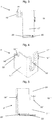
- FIG. 1 an embodiment of a device mounting box 1 according to the invention is shown in a perspective view, wherein two reversibly insertable corner pieces 2, 2 'of the device mounting box 1 (see. Fig. 5 ) and the locking element 3 (see. Fig. 6 ) are not used in the device mounting box 1 according to the invention.
- the mounting element 1 according to the invention comprises an upwardly open housing 4 with a bottom part 5 and walls 6, 6 ', 6 ", 6"'.
- the wall 6 as a whole is integrally connected to the bottom part 4, while the walls 6 ', 6 "are connected only about half in one piece with the bottom part 4 of the mounting element 1.
- the bottom part 5 of the mounting member 1 has two preferably parallel to each other openings 8, 8 ', which are formed as free cuts and which are separated from each other by a web 9.
- the web 9 is designed to be raised, ie its thickness exceeds the thickness of the bottom part 5.
- the web 9 is formed thickest approximately in the middle of its longitudinal extension.
- a support member 10 is formed, which also contributes to the guiding of the locking element 3 when installing the device mounting box 1 according to the invention in a device installation channel 11.
- a retaining element 12, 12' designed as a spar is formed with a base 13, 13 'in the edge region of the bottom part 4.
- the holding elements 12, 12 ' is in each case a latching receptacle 14, 14' is provided, which is preferably designed as a slot-shaped locking receptacle and for locking the corner pieces 2, 2 'is used.
- a guide receptacle 15, 15' is arranged, whose guide region has an L-shaped cross section.
- At the wall 6 opposite side of the bottom element 4 is another, designed as a spar holding element 12 "with associated base 13" is arranged.
- the bottom plate 4 On its underside, the bottom plate 4 has a tapered edge region 16 at the edge region on which the holding element 12 "is arranged.
- FIGS. 2 to 5 show corner pieces 2, 2 'are inserted into the device mounting box 1, which in the FIGS. 2 to 5 are shown. It shows Fig. 2 First, a perspective view of a first corner piece 2, through which the wall 6 'completes and the wall 6'"is partially formed.”
- the first corner piece 2 comprises two sections 17, 17 'connected to one another via a rounded connection area, the section 17 forming the wall 6 'and has a cable entry 18.
- a latching element 19 is formed, which is inserted into the latching receptacle 14 of the support element 12 for installation of the first corner piece 2 into the device mounting box 1 according to the invention 17, a guide element 20 which has an L-shaped cross-section in the embodiment of the device mounting box 1 according to the invention described herein and is received in the guide receptacle 15 during insertion of the first corner piece 2 into the device mounting box 1 according to the invention.
- the section 17 ' forms a part of the wall 6 "' in the assembled state of the device installation box 1 according to the invention.”
- the section 17 ' has an extension 21 with a latching element 19' integrally formed thereon 21 a hole 22 is arranged, by means of which the latching element 19 'is given flexibility
- the latching element 19' is latched to the holding element 12 "of the bottom part 4.
- a clamp member 23 is arranged, which is in the form of two parallel webs formed and in which in the assembled state of the device mounting box 1 according to the invention the tapered edge portion 16 of the bottom plate 4 is added.
- Fig. 3 shows that in Fig. 2 illustrated first corner piece 2 in a side view.
- the arrangement of the latching elements 19, 19 ', the webs forming the clamp element 23 and the L-shape of the guide element 20 are more apparent.
- the second corner piece 2 ' is in Fig. 4 also shown in a perspective view. Analogous to the first corner piece 2, the second corner piece 2 'comprises two sections 17 ", 17"' which are connected to one another via a rounded connecting region.
- the section 17 “completes in the assembled state of the device mounting box 1 according to the invention the wall 6" and comprises a cable entry 18 ', while the portion 17''forms together with the portion 17' of the first corner piece 2, the wall 6 '"of the complete device mounting box 1 according to the invention ,
- a locking element 19 which is inserted for installation of the second corner piece 2 'in the device socket 1 according to the invention in the locking receptacle 14' of the holding element 12 '.
- the portion 17 "on the guide member 20 corresponding guide member 20 ' which in turn has an L-shaped cross-section and the insertion of the second corner piece 2' in the device socket 1 according to the invention in the guide receptacle 15 'is taken, which is made the side view of the second corner piece 2 'according to Fig. 5 evident.
- the portion 17 '" In the assembled state of the device mounting box 1 according to the invention, the portion 17 '"forms together with the portion 17' of the first corner piece 2, the wall 6"'.
- the section 17 '" has a recess 24 in which, in the assembled state, the extension 21 of the first corner piece 2 is accommodated
- the section 17'" has a molded-on latching element 19 '", again in the vicinity
- the slot-shaped hole 22 ' gives the latching element 19'"again the necessary flexibility.
- the locking element 19 ' In the assembled state of the device mounting box 1 according to the invention, the locking element 19 'is “locked to the holding element 12" of the bottom part 4.
- a clamp element 23' is arranged, which is also designed in the case of the second corner piece 2 'in the form of two parallel webs and in the assembled state of the device mounting box 1 according to the invention, a portion of the tapered edge region 16 the bottom plate 4.
- the shape of the guide element 20 'and the clamping element 23' are in the side view of the second corner piece according to Fig. 5 shown.
- Fig. 6 shows a perspective view of the device mounting box 1 according to the invention, wherein both the first corner piece 2 and the second corner piece 2 'are inserted into the device installation box 1.
- the sections 17 'and 17'" form the wall 6 '" of the upwardly open housing 4, wherein the extension 20 of the section 17' fills the recess 24 of the section 17 '.
- the latching elements 19' and 19 '"with the holding element 12" locked while the locking element 19 and 19 "in the locking receptacles 14, 14' of the holding elements 12, 12 'are added and the tapered edge portion 16 of the bottom part 4 in the clamping elements 23, 23' of the first or second corner piece 2, 2 'is received.
- Fig. 7 shows a cross-sectional view of the embodiment shown in the figures of the device mounting box 1 according to the invention in the inserted into a device installation channel 11 state, wherein the locking element 3 is inserted into the device mounting box 1.
- the device installation channel 11 has a retaining rail 26 which is arranged on the channel bottom 25 and which is designed as a DIN rail 26 in the present embodiment.
- the retaining rail 26 has on the side facing away from the device mounting box 1 side of the support rail 26 in the longitudinal direction of the device installation channel 11 extending recess 27, which allows a simplified wall mounting the device installation channel 11.
- locking projections 28, 28 ' are arranged, which cooperate with holding devices designed as a latching hooks 29, 29', which on the walls 6, 6 ', 6 ", 6'" of the housing 4 side facing away from the bottom part. 5 the device mounting box 1 are arranged.
- the holding devices 29 ' (it is at two holding devices 29 ', wherein the first in the cross-sectional view according to the other Fig.
- the locking element 3 is pressed along the guide 7 completely in the direction of the channel bottom 26.
- the support section 30 of the locking element 3 reaches a position in which it rests against the holding rail 26 on the side facing away from the flexible holding device 29 and thus presses the flexible holding device 29 more strongly against the latching projection 28 of the holding rail 26.
- further displacement of the device mounting box 1 according to the invention along the retaining rail 26 is effectively prevented. In this way, the position of the device mounting box 1 according to the invention is locked in the device installation channel 11.
- installation equipment such as sockets, switches, receivers of remote control systems, data outlets, phone sockets and the like can be inserted into the device mounting box 1 according to the invention and secured for example by screwing it.
Description
Die vorliegende Erfindung betrifft eine Geräteinbaudose für Geräteeinbaukanäle, die ein nach oben offenes Gehäuse mit einem Bodenteil und an einer Seite des Bodenteils angeordneten Wandungen sowie an der anderen Seite des Bodenteils angeordnete Haltevorrichtungen zur Befestigung der Geräteeinbaudose am Geräteeinbaukanal umfasst.The present invention relates to a device installation box for device installation channels, which comprises an upwardly open housing with a bottom part and arranged on one side of the bottom part walls and arranged on the other side of the bottom part holding devices for fixing the device mounting box on the device installation channel.
Derartige Geräteeinbaudosen für Geräteeinbaukanäle sind aus dem Stand der Technik bekannt. Beispielsweise beschreibt die
Diese und andere Aufgaben werden durch eine Geräteeinbaudose für Geräteeinbaukanäle mit den Merkmalen des Anspruchs 1 bzw. durch einen Geräteeinbaukanal mit den Merkmalen des Geräteeinbaukanals nach Anspruch 4 gelöst. Bevorzugte Ausführungsformen der erfindungsgemäßen Geräteeinbaudose sind in den abhängigen Ansprüchen beschrieben. Gemäß der vorliegenden Erfindung wurde erkannt, dass eine als Geräteeinbaudose zur Aufnahme von elektrischen Steckdosen einsetzbare Geräteeinbaudose auch als Geräteeinbaudose zur Aufnahme von Datendosen verwendet werden kann, wenn Teile der Wandungen reversibel von der Geräteeinbaudose abnehmbar sind. In diesem Zusammenhang bedeutet der Begriff "reversibel", dass die von der Geräteeinbaudose abnehmbaren Teile der Wandungen nach deren Abnahme auch wieder mit der Geräteeinbaudose verbunden bzw. an die Geräteeinbaudose wieder angebaut werden können, wodurch der Zustand der Geräteeinbaudose vor Abnahme der Teile der Wandungen wieder hergestellt wird, ohne das dazu Hilfsmittel wie Klebstoff oder ein geeignetes Verbindungsmittel (z. B. eine Schraube) eingesetzt werden muss.These and other objects are achieved by a device installation box for device installation channels with the features of
Dementsprechend liegt die vorliegende Erfindung in der Bereitstellung einer Geräteeinbaudose für Geräteeinbaukanäle, die ein nach oben offenes Gehäuse mit einem Bodenteil und an einer Seite des Bodenteils angeordneten Wandungen sowie an der anderen Seite des Bodenteils angeordnete Haltevorrichtungen zur Befestigung der Geräteinbaudosen am Geräteeinbaukanal umfasst, wobei zumindest Teile der Wandungen reversibel von der Geräteeinbaudose abnehmbar sind. Darüber hinaus liegt die vorliegende Erfindung in der Bereitstellung eines Geräteeinbaukanals, der mindestens eine derartige erfindungsgemäße Geräteeinbaudose umfasst. Die reversibel von der Geräteeinbaudose abnehmbaren Teile der Wandungen sind als Eckstücke ausgebildet. Auf diese Weise ist gewährleistet, dass die in die erfindungsgemäße Geräteeinbaudose aufzunehmenden Datendosen aufgrund der vorgeschriebenen Biegeradien für die zu verwendenden Datenkabel, die mit den Datendosen verbunden werden sollen, von einem weiten Bereich zugänglich sind bzw. die Datenleitungen in einem weiten Bereich in die erfindungsgemäße Geräteeinbaudose eintreten können. Die Eckstücke sind im zusammengesetzten Zustand der erfindungsgemäßen Geräteeinbaudose ineinander benachbarten Ecken der Geräteeinbaudose angeordnet. Auf diese Weise wird eine Seite der Geräteeinbaudose vollständig zugänglich. Dabei bilden Abschnitte zweier im zusammengesetzten Zustand in einander benachbarten Ecken der erfindungsgemäßen Geräteeinbaudose angeordnete Eckstücke zusammen eine Wandung der Geräteeinbaudose. Dadurch bleibt die ggf. offene Wandung der erfindungsgemäßen Geräteeinbaudose in ihrem vollständigen Zustand vollständig verschlossen. Dabei stehen die Abschnitte jeweils über Rastelemente mit einem Halteelement im Eingriff, was an dem Bodenteil angeordnet ist.Accordingly, the present invention is to provide a device installation box for device installation channels, which comprises an upwardly open housing with a bottom part and arranged on one side of the bottom part walls and arranged on the other side of the bottom part holding devices for fixing the device installation boxes on the device installation channel, wherein at least parts the walls are reversibly removable from the device installation box. In addition, the present invention is to provide a device installation channel comprising at least one such device installation box according to the invention. The reversibly removable from the device mounting box parts of the walls are designed as corner pieces. In this way it is ensured that the data cans to be accommodated in the device mounting box according to the invention are accessible from a wide range due to the prescribed bending radii for the data cables to be used, which are to be connected to the data outlets or the data lines in a wide range in the device mounting box according to the invention can enter. The corner pieces are arranged in the assembled state of the device installation box according to the invention in each other adjacent corners of the device installation box. In this way one side of the device installation box becomes fully accessible. there form sections of two arranged in the assembled state in each other adjacent corners of the device mounting box according to the invention corner pieces together a wall of the device installation box. As a result, the possibly open wall of the device installation box according to the invention remains completely closed in its complete state. In this case, the sections in each case via latching elements with a holding element in engagement, which is arranged on the bottom part.
Ein derartiges Halteelement gewährleistet einen stabilen Sitz der beiden mit dem Halteelement verbundenen Eckstücke.Such a holding element ensures a stable fit of the two corner pieces connected to the holding element.
Es kann auch hilfreich sein, wenn das Bodenteil an seinem Randbereich zumindest teilweise eine verringerte Dicke aufweist, die im zusammengesetzten Zustand der erfindungsgemäßen Geräteeinbaudose zumindest teilweise in mit den Randbereichen mit verringerter Dicke kooperierenden Klammerelementen der Eckstücke aufgenommen ist. Auf diese Weise ist ein stabiler Sitz der in die erfindungsgemäße Geräteeinbaudose eingesetzten Eckstücke am Bodenteil gewährleistet.It may also be helpful if the bottom part at its edge region at least partially has a reduced thickness, which is added in the assembled state of the device mounting box according to the invention at least partially in cooperating with the edge regions with reduced thickness clamping elements of the corner pieces. In this way, a stable seat of the corner pieces used in the device mounting box according to the invention is ensured on the bottom part.
Es kann auch von Vorteil sein, wenn das Bodenteil an seinem Randbereich zumindest eine Führungsaufnahme aufweist, in die im zusammengesetzten Zustand der erfindungsgemäßen Geräteeinbaudose ein an den abnehmbaren Teilen der Wandungen angeordnetes Führungselement aufgenommen ist. Ein derartiges Führungssystem gewährleistet ein einfaches Einfügen der abgenommenen Teile der Wandungen und trägt darüber hinaus zu einem stabilen Sitz in der zusammengesetzten erfindungsgemäßen Geräteeinbaudose bei.It can also be advantageous if the bottom part has at its edge region at least one guide receptacle, in which in the assembled state of the device mounting box according to the invention a arranged on the removable parts of the walls guide element is added. Such a guide system ensures easy insertion of the removed parts of the walls and also contributes to a stable fit in the assembled device mounting box according to the invention.
Zur Herstellung der erfindungsgemäßen Geräteeinbaudose und der dazugehörigen Eckstücke hat sich Spritzgießen als bevorzugte Art der Herstellung erwiesen. Polyvinylchlorid (PVC), Polyethylen (insbesondere HDPE), Polyamid (PA; insbesondere Polyamid-6 und Polyamid-6,6) und Polypropylen (insbesondere statistisches Polypropylen PP-R) dienen als bevorzugte Materialien für die erfindungsgemäße Geräteeinbaudose. Während für erfindungsgemäße Geräteeinbaukanäle dieselben Materialien bevorzugt sind, werden diese in an sich bekannter Weise bevorzugt mittels Spritzguss hergestellt.In order to produce the appliance installation box according to the invention and the associated corner pieces, injection molding has proven to be the preferred mode of production. Polyvinyl chloride (PVC), polyethylene (especially HDPE), polyamide (PA, in particular polyamide-6 and polyamide-6,6) and polypropylene (in particular random polypropylene PP-R) serve as preferred materials for the appliance installation box according to the invention. While the same materials are preferred for device installation channels according to the invention, they are preferably produced in a manner known per se by means of injection molding.
Im Folgenden soll die vorliegende Erfindung unter Bezugnahme auf die in den Figuren dargestellte Ausführungsform im Detail erläutert werden. Dabei zeigen:
- Fig. 1
- eine perspektivische Ansicht einer Ausführungsform einer erfindungsgemäßen Geräteeinbaudose mit zwei abgenommenen Eckteilen;
- Fig. 2
- eine perspektivische Ansicht eines ersten Eckstücks;
- Fig. 3
- eine Seitenansicht des in
Fig. 2 gezeigten ersten Eckstücks; - Fig. 4
- eine perspektivische Ansicht eines zweiten Eckstücks;
- Fig. 5
- eine Seitenansicht des in
Fig. 4 gezeigten zweiten Eckstücks; - Fig. 6
- eine perspektivische Ansicht der in
Fig. 1 dargestellten Geräteeinbaudose mit eingesetztem ersten und zweiten Eckstück; und - Fig. 7
- eine Querschnittsdarstellung der in den Figuren gezeigten Ausführungsform der erfindungsgemäßen Geräteeinbaudose in in einen Geräteeinbaukanal eingesetzten Zustand mit eingesetztem Arretierungselement.
- Fig. 1
- a perspective view of an embodiment of a device installation box according to the invention with two removed corner parts;
- Fig. 2
- a perspective view of a first corner piece;
- Fig. 3
- a side view of the in
Fig. 2 shown first corner piece; - Fig. 4
- a perspective view of a second corner piece;
- Fig. 5
- a side view of the in
Fig. 4 shown second corner piece; - Fig. 6
- a perspective view of in
Fig. 1 illustrated device installation box with inserted first and second corner piece; and - Fig. 7
- a cross-sectional view of the embodiment of the device mounting box according to the invention shown in the figures in inserted into a device installation channel state with inserted locking element.
In
Das Bodenteil 5 des Montageelements 1 weist zwei vorzugsweise parallel zueinander verlaufende Öffnungen 8, 8' auf, die als Freischnitte ausgebildet sind und die voneinander durch einen Steg 9 getrennt sind. In der in
Etwa in der Mitte der Wandungen 6', 6" ist im Randbereich des Bodenteils 4 jeweils ein als Holm ausgebildetes Halteelement 12, 12' mit einem Sockel 13, 13' ausgebildet. An der zum freien Teil der Wandungen 6', 6" gerichteten Seite der Haltelemente 12, 12' ist jeweils eine Rastaufnahme 14, 14' vorhanden, die vorzugsweise als schlitzförmige Rastaufnahme ausgebildet ist und zum Verrasten der Eckstücke 2, 2' dient. An dem jeweiligen Sockel 13, 13' ist eine Führungsaufnahme 15, 15' angeordnet, deren Führungsbereich einen L-förmigen Querschnitt besitzt. An der der Wandung 6 gegenüberliegenden Seite des Bodenelements 4 ist ein weiteres, als Holm ausgebildetes Halteelement 12" mit zugehörigem Sockel 13" angeordnet. Zur offenen Oberseite des Gehäuses 4 hin weisen die Halteelemente 12, 12', 12" sowie die Führung 7 Bohrungen zur Aufnahme von Schrauben auf, mit der die in die erfindungsgemäße Geräteeinbaudose 1 einzusetzenden Installationsgeräte wie Steckdosen, Datendosen, Empfänger für Fernsteuerungssysteme und dergleichen durch Verschraubung an der Geräteeinbaudose 1 festgelegt werden können.Approximately in the middle of the
An ihrer Unterseite weist die Bodenplatte 4 an dem Randbereich, an dem das Halteelement 12" angeordnet ist, einen verjüngten Randbereich 16 auf.On its underside, the
Um das nach oben offene Gehäuse 4 zu vervollständigen, werden Eckstücke 2, 2' in die Geräteeinbaudose 1 eingesetzt, die in den
Der Abschnitt 17' bildet im zusammengesetzten Zustand der erfindungsgemäßen Geräteeinbaudose 1 einen Teil der Wandung 6"'. An einer Seite weist der Abschnitt 17' eine Verlängerung 21 mit daran angeformtem Rastelement 19' auf. In der Nähe des Rastelements 19' ist in der Verlängerung 21 ein Loch 22 angeordnet, durch das dem Rastelement 19' Flexibilität verliehen wird. Im zusammengesetzten Zustand der erfindungsgemäßen Geräteeinbaudose 1 ist das Rastelement 19' mit dem Halteelement 12" des Bodenteils 4 verrastet. Am unteren Bereich des Abschnitts 17' ist ein Klammerelement 23 angeordnet, das in Form zweier parallel zueinander ausgebildeter Stege ausgebildet ist und in das im zusammengesetzten Zustand der erfindungsgemäßen Geräteeinbaudose 1 der verjüngte Randbereich 16 der Bodenplatte 4 aufgenommen ist.The section 17 'forms a part of the
Das zweite Eckstück 2' ist in
Im zusammengesetzten Zustand der erfindungsgemäßen Geräteeinbaudose 1 bildet der Abschnitt 17'" zusammen mit dem Abschnitt 17' des ersten Eckstücks 2 die Wandung 6"'. Hierzu weist der Abschnitt 17'" eine Ausnehmung 24 auf, in der im zusammengesetzten Zustand die Verlängerung 21 des ersten Eckstücks 2 aufgenommen ist. Auf einer Seite weist der Abschnitt 17'" ein angeformtes Rastelement 19'" auf, wobei wiederum in der Nähe des Rastelements 19'" ein schlitzförmiges Loch 22' angeordnet ist. Das schlitzförmige Loch 22' verleiht dem Rastelement 19'" wiederum die nötige Flexibilität. Im zusammengesetzten Zustand der erfindungsgemäßen Geräteeinbaudose 1 ist das Rastelement 19'" mit dem Halteelement 12" des Bodenteils 4 verrastet. Am unteren Bereich des Abschnitts 17'" ist wiederum ein Klammerelement 23' angeordnet, das auch im Fall des zweiten Eckstücks 2' in Form zweier parallel zueinander ausgebildeter Stege ausgebildet ist und in das im zusammengesetzten Zustand der erfindungsgemäßen Geräteeinbaudose 1 ein Abschnitt des verjüngten Randbereichs 16 der Bodenplatte 4 aufgenommen ist. Die Form des Führungselements 20' sowie des Klammerelements 23' sind in der Seitenansicht des zweiten Eckstücks gemäß
Die Halteschiene 26 weist an der der erfindungsgemäßen Geräteeinbaudose 1 abgewandten Seite der Halteschiene 26 eine sich in Längsrichtung des Geräteeinbaukanals 11 erstreckende Ausnehmung 27 auf, die eine vereinfachte Wandmontage des Geräteeinbaukanals 11 ermöglicht. An beiden Seiten der Halteschiene 26 sind Rastvorsprünge 28, 28' angeordnet, die mit als Rasthaken ausgebildeten Haltevorrichtungen 29, 29' kooperieren, die an der den Wandungen 6, 6', 6", 6'" des Gehäuses 4 abgewandten Seite des Bodenteils 5 der Geräteeinbaudose 1 angeordnet sind. Zum Einbau der Geräteeinbaudose 1 in den Geräteeinbaukanal 11 werden zunächst die Haltevorrichtungen 29' (es handelt sich um zwei Haltevorrichtungen 29', wobei die erste die andere in der Querschnittsdarstellung gemäß
Nachdem die erfindungsgemäße Geräteeinbaudose 1 in ihre exakte Position in Längsrichtung des Geräteeinbaukanals 11 gebracht worden ist, wird das Arretierungselement 3 entlang der Führung 7 vollständig in Richtung des Kanalbodens 26 gedrückt. Dadurch gelangt der Stützabschnitt 30 des Arretierungselements 3 in eine Position, in der er an der Halteschiene 26 abgewandten Seite der flexiblen Haltevorrichtung 29 anliegt und so die flexiblen Haltevorrichtung 29 stärker gegen den Rastvorsprung 28 der Halteschiene 26 presst. Dadurch wird ein weiteres Verschieben der erfindungsgemäßen Geräteeinbaudose 1 entlang der Halteschiene 26 wirksam verhindert. Auf diese Weise ist die Position der erfindungsgemäßen Geräteeinbaudose 1 in dem Geräteeinbaukanal 11 arretiert.After the
Nach einer derartigen Montage des der erfindungsgemäßen Geräteeinbaudose 1 in den Geräteinbaukanal 11 können Installationsgeräte wie Steckdosen, Schalter, Empfänger von Fernsteuerungssystemen, Datendosen, Telefondosen und dergleichen in die erfindungsgemäße Geräteeinbaudose 1 eingesetzt und beispielsweise durch Verschraubung darin befestigt werden.After such installation of the
Die vorliegende Erfindung wurde unter Bezugnahme auf die in den Figuren gezeigte Ausführungsform der erfindungsgemäßen Geräteeinbaudose im Detail erläutert. Es versteht sich, dass die Erfindung nicht auf die dargestellte Ausführungsform beschränkt ist.The present invention has been explained in detail with reference to the embodiment of the device installation box according to the invention shown in FIGS. It is understood that the invention is not limited to the illustrated embodiment.
Claims (4)
- Device installation socket (1) for device installation channels (11), which comprises an upwardly open housing (4) with a bottom part (5) and walls (6, 6', 6", 6"') arranged on one side of the bottom part (5) and holding devices (29, 29'), which are arranged on the other side of the bottom part (5), for fastening the device installation socket (1) to the device installation channel (11), wherein at least parts of the walls (6, 6', 6", 6"') are reversibly removable from the device installation socket (1), and those parts of the walls (6, 6', 6", 6"') which are reversibly removable from the device installation socket (1) are designed as corner pieces (2, 2'), characterized in that, in the assembled state of the device installation socket (1), the corner pieces (2, 2') are arranged in mutually adjacent corners of the device installation socket (1), wherein portions (17', 17'") of two corner pieces (2, 2') arranged in mutually adjacent corners of the device installation socket (1) in the assembled state together form one of the walls (6'") of the device installation socket (1) and are each in engagement via latching elements (19', 19'") with a holding element (12") which is arranged on the bottom part (5) of the housing (4).
- Device installation socket (1) for device installation channels (11) according to Claim 1, characterized in that at least parts of the edge region of the bottom part (5) of the housing (4) have a reduced thickness which, in the assembled state of the device installation socket (1), is at least partially accommodated in clip elements (23, 23') of the corner pieces (2, 2'), said clip elements co-operating with said edge region parts.
- Device installation socket (1) for device installation channels (11) according to Claim 1 or Claim 2, characterized in that the edge region of the bottom part (5) of the housing (4) has at least one guide receptacle (15, 15') in which, in the assembled state of the device installation socket (1), a guide element (20, 20') arranged on the removable parts of the walls (6, 6', 6", 6'") is accommodated.
- Device installation channel (11) which comprises at least one device installation socket (1) for device installation channels (11) according to one of Claims 1 to 3.
Applications Claiming Priority (1)
| Application Number | Priority Date | Filing Date | Title |
|---|---|---|---|
| DE202012100876U DE202012100876U1 (en) | 2012-03-12 | 2012-03-12 | Device mounting box for device installation trunking as well as this comprehensive device installation trunking |
Publications (3)
| Publication Number | Publication Date |
|---|---|
| EP2639912A2 EP2639912A2 (en) | 2013-09-18 |
| EP2639912A3 EP2639912A3 (en) | 2014-03-12 |
| EP2639912B1 true EP2639912B1 (en) | 2017-07-19 |
Family
ID=45999463
Family Applications (1)
| Application Number | Title | Priority Date | Filing Date |
|---|---|---|---|
| EP13158521.8A Active EP2639912B1 (en) | 2012-03-12 | 2013-03-11 | Device installation socket for device installation channels and device installation channel comprising same |
Country Status (2)
| Country | Link |
|---|---|
| EP (1) | EP2639912B1 (en) |
| DE (1) | DE202012100876U1 (en) |
Families Citing this family (1)
| Publication number | Priority date | Publication date | Assignee | Title |
|---|---|---|---|---|
| DE102014217481A1 (en) * | 2014-09-02 | 2016-03-03 | Fränkische Rohrwerke Gebr. Kirchner Gmbh & Co. Kg | connection unit |
Family Cites Families (5)
| Publication number | Priority date | Publication date | Assignee | Title |
|---|---|---|---|---|
| DE3112347C2 (en) | 1981-03-28 | 1983-09-01 | Günther Spelsberg GmbH & Co KG, 5885 Schalksmühle | Installation box for electrical installation devices |
| DE3926062A1 (en) * | 1988-08-30 | 1991-02-14 | Spelsberg Guenther Gmbh Co Kg | Wall-mounted double socket esp. for cable duct - comprises modular end pieces and intermediate pieces with overlap of reduced thickness on diagonals with hook fastenings |
| FR2649253B1 (en) * | 1989-07-03 | 1994-02-11 | Legrand | TWO-PART RECESSED BOX, ESPECIALLY FOR ELECTRICAL EQUIPMENT |
| DE10003922C2 (en) * | 2000-01-29 | 2002-03-07 | Kleinhuis Hermann Gmbh | Installation box for use in a cable duct, such as a parapet duct |
| DE10119113A1 (en) * | 2001-04-19 | 2002-10-24 | Niedax Gmbh | Equipment support arrangement e.g. for electrical communication equipment, has opposite facing extensions with associated arms forming U-shaped structure |
-
2012
- 2012-03-12 DE DE202012100876U patent/DE202012100876U1/en not_active Expired - Lifetime
-
2013
- 2013-03-11 EP EP13158521.8A patent/EP2639912B1/en active Active
Non-Patent Citations (1)
| Title |
|---|
| None * |
Also Published As
| Publication number | Publication date |
|---|---|
| EP2639912A3 (en) | 2014-03-12 |
| DE202012100876U1 (en) | 2012-03-28 |
| EP2639912A2 (en) | 2013-09-18 |
Similar Documents
| Publication | Publication Date | Title |
|---|---|---|
| EP3292604B1 (en) | Method for producing a wall lead-through for a plurality cables and arrangement | |
| DE2544893C2 (en) | Electrical connecting element for a clamp connection and an electrical connection | |
| EP3152809A2 (en) | Electric device | |
| EP2916409A2 (en) | Frame for cable feedthroughs, fastening elements and cable feedthrough system | |
| EP3016215A1 (en) | Grounding rail device | |
| EP2012390A2 (en) | Ground clamp for potential equalisation of cable conduits | |
| DE102016111847B4 (en) | Through terminal | |
| EP2806516A1 (en) | Seal block for individual wires | |
| EP2639912B1 (en) | Device installation socket for device installation channels and device installation channel comprising same | |
| EP2639911B1 (en) | Mounting element for device installation channels, device installation channel with such a mounting element and method for mounting such a mounting element in a device installation channel | |
| EP2639910B1 (en) | Device installation socket for device installation channels and equipment installation channel comprising same | |
| DE2625321A1 (en) | ELECTRICAL INSTALLATION EQUIPMENT | |
| DE102009029434B4 (en) | Adapter for mounting electrical installation devices and for mounting on a busbar system | |
| EP2650994B1 (en) | Socket assembly for device installation assemblies with a holding rail at the channel base and device installation channel comprising such a socket assembly | |
| EP3658787B1 (en) | Shaped component, method for connecting at least one metal-sheet component to a shaped component, and system of a metal-sheet construction | |
| EP1463170B1 (en) | Meter- or distribution cabinet | |
| EP3139714B1 (en) | Housing for an electronic component | |
| EP2418746A2 (en) | Device socket for installation devices | |
| EP2690729A1 (en) | Electrical installation system and dry wall box for electric installation | |
| EP3675297B1 (en) | Holding element for an installation device | |
| EP2503643B1 (en) | Clamp device for connecting electrical lines and tool for same | |
| AT522412B1 (en) | Installation box and installation box arrangement with such an installation box | |
| EP2896861B1 (en) | Adjustable installation console for fitting a line guidance channel to a wall | |
| EP2953221B1 (en) | Device holder for electric installation devices | |
| EP1460322A1 (en) | Fixing device for flat, elongated elements, in particular for flat cables |
Legal Events
| Date | Code | Title | Description |
|---|---|---|---|
| PUAI | Public reference made under article 153(3) epc to a published international application that has entered the european phase |
Free format text: ORIGINAL CODE: 0009012 |
|
| AK | Designated contracting states |
Kind code of ref document: A2 Designated state(s): AL AT BE BG CH CY CZ DE DK EE ES FI FR GB GR HR HU IE IS IT LI LT LU LV MC MK MT NL NO PL PT RO RS SE SI SK SM TR |
|
| AX | Request for extension of the european patent |
Extension state: BA ME |
|
| PUAL | Search report despatched |
Free format text: ORIGINAL CODE: 0009013 |
|
| AK | Designated contracting states |
Kind code of ref document: A3 Designated state(s): AL AT BE BG CH CY CZ DE DK EE ES FI FR GB GR HR HU IE IS IT LI LT LU LV MC MK MT NL NO PL PT RO RS SE SI SK SM TR |
|
| AX | Request for extension of the european patent |
Extension state: BA ME |
|
| RIC1 | Information provided on ipc code assigned before grant |
Ipc: H02G 3/08 20060101ALI20140203BHEP Ipc: H02G 3/12 20060101AFI20140203BHEP Ipc: H02G 3/04 20060101ALI20140203BHEP |
|
| 17P | Request for examination filed |
Effective date: 20140911 |
|
| RBV | Designated contracting states (corrected) |
Designated state(s): AL AT BE BG CH CY CZ DE DK EE ES FI FR GB GR HR HU IE IS IT LI LT LU LV MC MK MT NL NO PL PT RO RS SE SI SK SM TR |
|
| GRAP | Despatch of communication of intention to grant a patent |
Free format text: ORIGINAL CODE: EPIDOSNIGR1 |
|
| RIC1 | Information provided on ipc code assigned before grant |
Ipc: H02G 3/04 20060101ALI20170214BHEP Ipc: H02G 3/08 20060101ALI20170214BHEP Ipc: H02G 3/12 20060101AFI20170214BHEP |
|
| INTG | Intention to grant announced |
Effective date: 20170228 |
|
| GRAS | Grant fee paid |
Free format text: ORIGINAL CODE: EPIDOSNIGR3 |
|
| GRAA | (expected) grant |
Free format text: ORIGINAL CODE: 0009210 |
|
| AK | Designated contracting states |
Kind code of ref document: B1 Designated state(s): AL AT BE BG CH CY CZ DE DK EE ES FI FR GB GR HR HU IE IS IT LI LT LU LV MC MK MT NL NO PL PT RO RS SE SI SK SM TR |
|
| REG | Reference to a national code |
Ref country code: GB Ref legal event code: FG4D Free format text: NOT ENGLISH |
|
| REG | Reference to a national code |
Ref country code: CH Ref legal event code: EP |
|
| REG | Reference to a national code |
Ref country code: IE Ref legal event code: FG4D Free format text: LANGUAGE OF EP DOCUMENT: GERMAN |
|
| REG | Reference to a national code |
Ref country code: AT Ref legal event code: REF Ref document number: 911248 Country of ref document: AT Kind code of ref document: T Effective date: 20170815 |
|
| REG | Reference to a national code |
Ref country code: DE Ref legal event code: R096 Ref document number: 502013007780 Country of ref document: DE |
|
| REG | Reference to a national code |
Ref country code: NL Ref legal event code: MP Effective date: 20170719 |
|
| REG | Reference to a national code |
Ref country code: LT Ref legal event code: MG4D |
|
| PG25 | Lapsed in a contracting state [announced via postgrant information from national office to epo] |
Ref country code: NO Free format text: LAPSE BECAUSE OF FAILURE TO SUBMIT A TRANSLATION OF THE DESCRIPTION OR TO PAY THE FEE WITHIN THE PRESCRIBED TIME-LIMIT Effective date: 20171019 Ref country code: FI Free format text: LAPSE BECAUSE OF FAILURE TO SUBMIT A TRANSLATION OF THE DESCRIPTION OR TO PAY THE FEE WITHIN THE PRESCRIBED TIME-LIMIT Effective date: 20170719 Ref country code: SE Free format text: LAPSE BECAUSE OF FAILURE TO SUBMIT A TRANSLATION OF THE DESCRIPTION OR TO PAY THE FEE WITHIN THE PRESCRIBED TIME-LIMIT Effective date: 20170719 Ref country code: LT Free format text: LAPSE BECAUSE OF FAILURE TO SUBMIT A TRANSLATION OF THE DESCRIPTION OR TO PAY THE FEE WITHIN THE PRESCRIBED TIME-LIMIT Effective date: 20170719 Ref country code: NL Free format text: LAPSE BECAUSE OF FAILURE TO SUBMIT A TRANSLATION OF THE DESCRIPTION OR TO PAY THE FEE WITHIN THE PRESCRIBED TIME-LIMIT Effective date: 20170719 Ref country code: HR Free format text: LAPSE BECAUSE OF FAILURE TO SUBMIT A TRANSLATION OF THE DESCRIPTION OR TO PAY THE FEE WITHIN THE PRESCRIBED TIME-LIMIT Effective date: 20170719 |
|
| REG | Reference to a national code |
Ref country code: FR Ref legal event code: PLFP Year of fee payment: 6 |
|
| PG25 | Lapsed in a contracting state [announced via postgrant information from national office to epo] |
Ref country code: PL Free format text: LAPSE BECAUSE OF FAILURE TO SUBMIT A TRANSLATION OF THE DESCRIPTION OR TO PAY THE FEE WITHIN THE PRESCRIBED TIME-LIMIT Effective date: 20170719 Ref country code: ES Free format text: LAPSE BECAUSE OF FAILURE TO SUBMIT A TRANSLATION OF THE DESCRIPTION OR TO PAY THE FEE WITHIN THE PRESCRIBED TIME-LIMIT Effective date: 20170719 Ref country code: GR Free format text: LAPSE BECAUSE OF FAILURE TO SUBMIT A TRANSLATION OF THE DESCRIPTION OR TO PAY THE FEE WITHIN THE PRESCRIBED TIME-LIMIT Effective date: 20171020 Ref country code: LV Free format text: LAPSE BECAUSE OF FAILURE TO SUBMIT A TRANSLATION OF THE DESCRIPTION OR TO PAY THE FEE WITHIN THE PRESCRIBED TIME-LIMIT Effective date: 20170719 Ref country code: IS Free format text: LAPSE BECAUSE OF FAILURE TO SUBMIT A TRANSLATION OF THE DESCRIPTION OR TO PAY THE FEE WITHIN THE PRESCRIBED TIME-LIMIT Effective date: 20171119 Ref country code: RS Free format text: LAPSE BECAUSE OF FAILURE TO SUBMIT A TRANSLATION OF THE DESCRIPTION OR TO PAY THE FEE WITHIN THE PRESCRIBED TIME-LIMIT Effective date: 20170719 Ref country code: BG Free format text: LAPSE BECAUSE OF FAILURE TO SUBMIT A TRANSLATION OF THE DESCRIPTION OR TO PAY THE FEE WITHIN THE PRESCRIBED TIME-LIMIT Effective date: 20171019 |
|
| REG | Reference to a national code |
Ref country code: DE Ref legal event code: R097 Ref document number: 502013007780 Country of ref document: DE |
|
| PG25 | Lapsed in a contracting state [announced via postgrant information from national office to epo] |
Ref country code: DK Free format text: LAPSE BECAUSE OF FAILURE TO SUBMIT A TRANSLATION OF THE DESCRIPTION OR TO PAY THE FEE WITHIN THE PRESCRIBED TIME-LIMIT Effective date: 20170719 Ref country code: RO Free format text: LAPSE BECAUSE OF FAILURE TO SUBMIT A TRANSLATION OF THE DESCRIPTION OR TO PAY THE FEE WITHIN THE PRESCRIBED TIME-LIMIT Effective date: 20170719 Ref country code: CZ Free format text: LAPSE BECAUSE OF FAILURE TO SUBMIT A TRANSLATION OF THE DESCRIPTION OR TO PAY THE FEE WITHIN THE PRESCRIBED TIME-LIMIT Effective date: 20170719 |
|
| PLBE | No opposition filed within time limit |
Free format text: ORIGINAL CODE: 0009261 |
|
| STAA | Information on the status of an ep patent application or granted ep patent |
Free format text: STATUS: NO OPPOSITION FILED WITHIN TIME LIMIT |
|
| PG25 | Lapsed in a contracting state [announced via postgrant information from national office to epo] |
Ref country code: IT Free format text: LAPSE BECAUSE OF FAILURE TO SUBMIT A TRANSLATION OF THE DESCRIPTION OR TO PAY THE FEE WITHIN THE PRESCRIBED TIME-LIMIT Effective date: 20170719 Ref country code: SK Free format text: LAPSE BECAUSE OF FAILURE TO SUBMIT A TRANSLATION OF THE DESCRIPTION OR TO PAY THE FEE WITHIN THE PRESCRIBED TIME-LIMIT Effective date: 20170719 Ref country code: SM Free format text: LAPSE BECAUSE OF FAILURE TO SUBMIT A TRANSLATION OF THE DESCRIPTION OR TO PAY THE FEE WITHIN THE PRESCRIBED TIME-LIMIT Effective date: 20170719 Ref country code: EE Free format text: LAPSE BECAUSE OF FAILURE TO SUBMIT A TRANSLATION OF THE DESCRIPTION OR TO PAY THE FEE WITHIN THE PRESCRIBED TIME-LIMIT Effective date: 20170719 |
|
| 26N | No opposition filed |
Effective date: 20180420 |
|
| PG25 | Lapsed in a contracting state [announced via postgrant information from national office to epo] |
Ref country code: SI Free format text: LAPSE BECAUSE OF FAILURE TO SUBMIT A TRANSLATION OF THE DESCRIPTION OR TO PAY THE FEE WITHIN THE PRESCRIBED TIME-LIMIT Effective date: 20170719 |
|
| PG25 | Lapsed in a contracting state [announced via postgrant information from national office to epo] |
Ref country code: MT Free format text: LAPSE BECAUSE OF FAILURE TO SUBMIT A TRANSLATION OF THE DESCRIPTION OR TO PAY THE FEE WITHIN THE PRESCRIBED TIME-LIMIT Effective date: 20170719 |
|
| REG | Reference to a national code |
Ref country code: CH Ref legal event code: PL |
|
| PG25 | Lapsed in a contracting state [announced via postgrant information from national office to epo] |
Ref country code: MC Free format text: LAPSE BECAUSE OF FAILURE TO SUBMIT A TRANSLATION OF THE DESCRIPTION OR TO PAY THE FEE WITHIN THE PRESCRIBED TIME-LIMIT Effective date: 20170719 |
|
| REG | Reference to a national code |
Ref country code: BE Ref legal event code: MM Effective date: 20180331 |
|
| REG | Reference to a national code |
Ref country code: IE Ref legal event code: MM4A |
|
| PG25 | Lapsed in a contracting state [announced via postgrant information from national office to epo] |
Ref country code: LU Free format text: LAPSE BECAUSE OF NON-PAYMENT OF DUE FEES Effective date: 20180311 |
|
| PG25 | Lapsed in a contracting state [announced via postgrant information from national office to epo] |
Ref country code: IE Free format text: LAPSE BECAUSE OF NON-PAYMENT OF DUE FEES Effective date: 20180311 |
|
| PG25 | Lapsed in a contracting state [announced via postgrant information from national office to epo] |
Ref country code: BE Free format text: LAPSE BECAUSE OF NON-PAYMENT OF DUE FEES Effective date: 20180331 Ref country code: LI Free format text: LAPSE BECAUSE OF NON-PAYMENT OF DUE FEES Effective date: 20180331 Ref country code: CH Free format text: LAPSE BECAUSE OF NON-PAYMENT OF DUE FEES Effective date: 20180331 |
|
| REG | Reference to a national code |
Ref country code: AT Ref legal event code: MM01 Ref document number: 911248 Country of ref document: AT Kind code of ref document: T Effective date: 20180311 |
|
| PG25 | Lapsed in a contracting state [announced via postgrant information from national office to epo] |
Ref country code: AT Free format text: LAPSE BECAUSE OF NON-PAYMENT OF DUE FEES Effective date: 20180311 |
|
| REG | Reference to a national code |
Ref country code: DE Ref legal event code: R081 Ref document number: 502013007780 Country of ref document: DE Owner name: OBO BETTERMANN PRODUKTION DEUTSCHLAND GMBH & C, DE Free format text: FORMER OWNER: REHAU AG + CO, 95111 REHAU, DE |
|
| PG25 | Lapsed in a contracting state [announced via postgrant information from national office to epo] |
Ref country code: TR Free format text: LAPSE BECAUSE OF FAILURE TO SUBMIT A TRANSLATION OF THE DESCRIPTION OR TO PAY THE FEE WITHIN THE PRESCRIBED TIME-LIMIT Effective date: 20170719 |
|
| PGFP | Annual fee paid to national office [announced via postgrant information from national office to epo] |
Ref country code: GB Payment date: 20200325 Year of fee payment: 8 |
|
| PG25 | Lapsed in a contracting state [announced via postgrant information from national office to epo] |
Ref country code: HU Free format text: LAPSE BECAUSE OF FAILURE TO SUBMIT A TRANSLATION OF THE DESCRIPTION OR TO PAY THE FEE WITHIN THE PRESCRIBED TIME-LIMIT; INVALID AB INITIO Effective date: 20130311 Ref country code: PT Free format text: LAPSE BECAUSE OF FAILURE TO SUBMIT A TRANSLATION OF THE DESCRIPTION OR TO PAY THE FEE WITHIN THE PRESCRIBED TIME-LIMIT Effective date: 20170719 |
|
| PG25 | Lapsed in a contracting state [announced via postgrant information from national office to epo] |
Ref country code: CY Free format text: LAPSE BECAUSE OF FAILURE TO SUBMIT A TRANSLATION OF THE DESCRIPTION OR TO PAY THE FEE WITHIN THE PRESCRIBED TIME-LIMIT Effective date: 20170719 Ref country code: MK Free format text: LAPSE BECAUSE OF NON-PAYMENT OF DUE FEES Effective date: 20170719 |
|
| PG25 | Lapsed in a contracting state [announced via postgrant information from national office to epo] |
Ref country code: AL Free format text: LAPSE BECAUSE OF FAILURE TO SUBMIT A TRANSLATION OF THE DESCRIPTION OR TO PAY THE FEE WITHIN THE PRESCRIBED TIME-LIMIT Effective date: 20170719 |
|
| GBPC | Gb: european patent ceased through non-payment of renewal fee |
Effective date: 20210311 |
|
| REG | Reference to a national code |
Ref country code: DE Ref legal event code: R082 Ref document number: 502013007780 Country of ref document: DE Representative=s name: HAVERKAMP PATENTANWAELTE PARTG MBB, DE |
|
| PG25 | Lapsed in a contracting state [announced via postgrant information from national office to epo] |
Ref country code: GB Free format text: LAPSE BECAUSE OF NON-PAYMENT OF DUE FEES Effective date: 20210311 |
|
| PGFP | Annual fee paid to national office [announced via postgrant information from national office to epo] |
Ref country code: FR Payment date: 20230320 Year of fee payment: 11 |
|
| PGFP | Annual fee paid to national office [announced via postgrant information from national office to epo] |
Ref country code: DE Payment date: 20230206 Year of fee payment: 11 |