EP1460322A1 - Fixing device for flat, elongated elements, in particular for flat cables - Google Patents
Fixing device for flat, elongated elements, in particular for flat cables Download PDFInfo
- Publication number
- EP1460322A1 EP1460322A1 EP04005931A EP04005931A EP1460322A1 EP 1460322 A1 EP1460322 A1 EP 1460322A1 EP 04005931 A EP04005931 A EP 04005931A EP 04005931 A EP04005931 A EP 04005931A EP 1460322 A1 EP1460322 A1 EP 1460322A1
- Authority
- EP
- European Patent Office
- Prior art keywords
- base
- holder
- flap
- fastening
- recess
- Prior art date
- Legal status (The legal status is an assumption and is not a legal conclusion. Google has not performed a legal analysis and makes no representation as to the accuracy of the status listed.)
- Granted
Links
Images


Classifications
-
- H—ELECTRICITY
- H02—GENERATION; CONVERSION OR DISTRIBUTION OF ELECTRIC POWER
- H02G—INSTALLATION OF ELECTRIC CABLES OR LINES, OR OF COMBINED OPTICAL AND ELECTRIC CABLES OR LINES
- H02G3/00—Installations of electric cables or lines or protective tubing therefor in or on buildings, equivalent structures or vehicles
- H02G3/30—Installations of cables or lines on walls, floors or ceilings
Definitions
- the invention relates to a device for fastening elongated, flat objects, in particular ribbon cables, to a base with a holder which has a holding area with means for holding at least one elongated, flat object and a fastening area which is intended for fastening the holder.
- Ribbon cables also called film conductors or ribbon cables
- a number of conductor tracks are applied next to one another on a thin, electrically insulating carrier layer and covered with an electrically insulating cover layer.
- Other designs of ribbon cables consist of a plurality of conductors which are arranged parallel to one another and covered by an insulator, with connecting sections of the insulator extending between adjacent conductors. When laying ribbon cables, it is necessary to attach them to a base at intervals.
- a clamp for holding a ribbon cable which comprises a U-shaped base part for receiving the ribbon cable, a cover part connected to the base part, a protrusion extending from the base part and a pressure part which presses on the cover part is arranged and holds the ribbon cable received by the base part downwards when the cover part is closed.
- a slot is provided in the ribbon cable into which the protrusion penetrates.
- a plurality of ribbon cables can also be fastened one above the other. Since the holding device can only be closed after all the lines to be fastened have been inserted into it, special aids have to be used in unfavorable installation positions, for example in an overhead arrangement, in order to hold the lower layers of the ribbon cables until the top layer has been inserted Device can be closed.
- DE 100 45 765 D1 discloses a deflection device for a film conductor, which has a deflection flap with a deflection edge and a protective edge. In the assembled state, the foil conductor is clamped between a base flap and the deflection flap on the one hand and between the deflection edge and the protective edge on the other hand.
- the deflection device enables the film conductor to be deflected, for example by 90 °, and at the same time serves for fastening it to a base.
- the invention has for its object to provide a device for fastening elongated, flat objects, in particular ribbon cables of the type mentioned, which is particularly easy to assemble and handle.
- the device has a base, which can be fastened separately from the holder on a base, for example on an automobile body, wherein associated coupling elements are provided on the base and on the fastening region of the holder, which are used to connect the holder to the base can be brought into an engagement position in which the holder is held on the base by means of the coupling elements.
- the means which are connected to the ribbon cable, namely the holder, and the means which are used for fastening to the base, namely the base, are separated from one another and can be firmly connected to one another by a simple, manually operated coupling
- the separation of the assembly processes expands the possibilities for their implementation and facilitates the use of assembly robots.
- Another advantage of the device according to the invention is that different fastening means such as bolts, screws, rivets, locking elements or adhesive connections can be used for fastening the base to the base without these assembly methods being hindered or impaired by the prior attachment of the ribbon cable or the There is a risk that the ribbon cable will be damaged during these assemblies
- the base has a recess for receiving at least one fastening region of a holder, the recess having grooves and / or projections forming coupling elements on at least two opposite sides and the fastening region of the holder interacting with the grooves of the base and / or with the projections of the base have cooperating grooves.
- This design of the coupling elements is easy to manufacture and enables simple movements during assembly.
- Grooves which are parallel to one another are preferably formed in opposite side walls of the recess in the base and are provided with at least one open end, the fastening region of the holder having projections which engage in the grooves when the holder is connected to the base.
- the holder with its fastening area on the side of the base facing away from the base, is turned towards the base directional first movement inserted into the recess of the base and then brought by a second movement transverse to this first movement into an engagement day, in which the holder is positively attached to the base.
- This sequence of movements for connecting the holder and base is for laying ribbon cables particularly cheap and enables a simple and easy-to-use design of the coupling elements.
- the grooves have a lateral recess and the projections of the holder are arranged on the lateral recesses of the grooves in the engagement position connected to the base and are supported there.
- a positive locking between the holder is achieved with simple means and base in the engagement position and an effective support of the holding forces is achieved.
- the fixing area of the holder in the engagement position can advantageously be fixed by a snap lock which snaps in as soon as the projections of the holder are in the engagement position on the lateral recesses.
- a further embodiment of the invention is particularly advantageous, in which the recess in the base has two or more sections which lie one above the other in parallel planes, each section being designed to accommodate a fastening region of a holder which is adapted in size to the respective section a multi-stage design of two opposite side walls of the recess can be separated from one another.
- This design makes it possible to fasten several holders lying on top of one another on one and the same base, with each holder being able to carry at least one ribbon cable.
- This allows several ribbon cables to be held one above the other, the assembly of the individual lines can be done independently of each other and each line is attached to the base with its holder separately. Additional aids for holding individual lines during assembly are not required.
- the base For its attachment to the base, the base can have an opening for receiving an attachment bolt projecting from the base with an undercut and retaining means engaging the undercut of the attachment bolt.
- the base can have on its underside facing the base be provided with a pin which can be inserted into an opening of the base and which has holding means engaging behind the opening.
- a preferred embodiment of the holder comprises an essentially plate-shaped base part, which forms the holding area and the fastening area in an adjacent arrangement, the holding area forming a support surface for an elongated, flat object, on both sides of the support surface with respect to this raised guide elements and one on the base part has pivotally attached flap, which engages over the object arranged on the contact surface in a locking position that can be held on the base part.
- the fastening area of the holder preferably has on its opposite sides adjoining the holder area two projections which are arranged at a distance from one another and which are intended to engage in grooves in the base, and is on its side opposite the holding area with a protruding part from the base part provided resilient tongue, which carries at its free end a locking hook interacting with the base.
- the fastening area of the holder can also be provided with a central opening. This opening creates a free space which is available when the holder is arranged in the base and can be used to arrange a means for fastening the base, for example a bolt or a screw.
- the flap can be connected to the holder by a film hinge.
- the flap has cylindrical journals that can be buttoned into a partially cylindrical bearing recess in the holder. It is particularly advantageous if the flap is completely symmetrical, so that the effort for positioning the flap during its assembly is minimal is.
- a snap hook can be attached to the holder or to the flap, which interacts with a projection on the flap or on the holder.It is also advantageous if the flap has projections on the hinge side that are in engage the closed position of the flap in a recess of the holder and additionally secure the flap on the hinge against loosening
- a raised rib made of a soft elastic material can be provided.
- the rib preferably consists of an insert which is inserted into a slot in the holder or the flap.
- the device according to the invention is also suitable for deflecting ribbon cables if the flap has a lateral deflection edge which runs at an angle corresponding to the deflection angle to the longitudinal direction of the ribbon cable. For deflection, the ribbon cable is folded around the deflection edge of the flap after the flap has been closed.
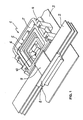
- FIG. 1 shows a fastening device 1 which is intended for fastening a plurality of ribbon cables 2 to a base 3, for example the body of an automobile.
- the fastening device 1 comprises a base 4 and a plurality of holders 5, which are arranged one above the other and are fastened with their fastening regions 6 in a central recess 7 of the base 4.
- Each holder 5 has a holding area 8, which extends outside the base 4 and to which the ribbon cable 2 is held by means of a closable flap 9.
- the base 4 is fastened to the base 3 with the aid of a T-bolt 10, which is buttoned into an opening in the base 4.
- the holder 5 has a base part 11 in the form of an essentially flat plate, which is divided into a rectangular holding area 8 and a fastening area 6.
- the fastening area 6 has the shape of a frame with a central opening 12 , two shorter frame legs 13, 14 and two longer frame legs 15
- the two longer frame legs 15 each carry two knob-like projections in a symmetrical arrangement on their outside 16, which serve to support the holder 5 on the base 4.
- the shorter frame leg 13, which is further away from the fastening area 6, has on its outside a resilient tongue 17 that extends parallel to the frame plane and has a snap hook 18 at its free end carries, the locking surface 19 of the snap hook 18 facing the frame leg 13
- the shorter frame leg 14 of the fastening area 6 is adjoined by the holding area 8, which in extension of the frame leg 15 has two legs 20 with contact surfaces 21 lying in a common plane.
- the legs 20 are separated from one another by an opening 22 and their ends opposite the frame legs 14 are connected to one another by a leg 23.
- the opening 22 is provided in order to be able to produce the holder in a simple molding tool which does not have a slide.
- the free end of the flap 24 is provided with a snap lug 26 which, for locking the flap 24 in the closed position, has a section facing the opening 22 of the leg 23 engages.
- the leg 23 forms, with extensions extending along the contact surfaces 21, a continuous rib 27 which projects from the contact surfaces 21 and forms a lateral contact for guiding and supporting a ribbon cable arranged on the contact surfaces 21.
- ribs 28 are provided on the legs 20, which also protrude from the respective contact surface 21 and form a lateral contact for the ribbon cable opposite the rib 27.
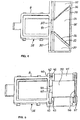
- FIG. 4 shows a holder 29, which differs from the holder 5 by a modification of its holding area 30 and which is suitable for deflecting a ribbon cable.
- the fastening area of the holder 29 corresponds to that of the holder 5.
- the holding area 30 has a trapezoidal flap 31 which is arranged above a trapezoidal opening 32.
- the short parallel side of the flap 31 is connected to the frame leg 14 of the fastening area 6 by a bending hinge 33.
- the long parallel side of the flap 31 is provided with a snap bar 34 which snaps into a recess in the outer leg 35 of the holding area 30 in order to hold the flap 31 in the closed position shown in the drawing.
- the side edges 36 of the flap 31 are inclined at an angle of 45 ° to the longitudinal axis of the leg 35.
- a ribbon cable inserted into the holding area 30 and held by the closed flap 31 can be deflected at an angle of 90 ° by folding over on one of the side edges 36. If the ribbon cable is folded over on both side edges 36, the ribbon cable is deflected by 180 °.
- the legs 37 of the holding area 30 located on both sides of the opening 32 serve to guide and support the ribbon cable if it is not deflected. When deflected, due to their overhang, they provide lateral protection for the folded edge of the ribbon cable
- FIG. 5 shows a holder 38 with a flap 39 which is produced separately from the holder 38 and is then movably connected to it.
- the base part 40 has in the holding area a closed plate 41 which extends under the flap 39 and which is attached to the holder 5 adjacent, reinforced longitudinal side has two spaced-apart bearing grooves 42.
- Cylindrical bearing journals 43 are arranged in the bearing grooves 42 at one end of the flap 39.
- the bearing pins 43 engage with more than half of their circumference in the bearing grooves 42.
- the opening width of the bearing grooves 42 is smaller than the diameter of the bearing pins, so that the bearing pins are held in the bearing grooves 42 in a form-fitting manner.
- the opening of the bearing grooves 42 is sufficiently large to enable the bearing pins 43 to be buttoned into the bearing grooves 42, taking advantage of the material-related elastic deformability.
- the flap 39 is additionally secured against loosening on its pivot axis formed by the bearing pin 43, which is located on the base part 40 in the middle between the bearing grooves 42 and engages in a recess 45 on the top of the flap 39.
- the edge of the recess 45 is so far away from the rib 44 that the insertion of the flap 39 into the bearing grooves 42 is not hindered by the rib 44.
- the flap 39 is also held in the closed position by a snap lock 46, which cooperates with a detent at its free end and is formed on an elastically deformable leg 47 of the base part 40
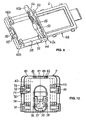
- the flap 50 which is produced separately from the base part 49, is completely symmetrical.
- the positional alignment of the flap 50 before assembly is simplified and automatic assembly of the flap 50 is facilitated
- Figure 5 has the flap 50 bearing pins 43a, 43b, which can be buttoned into bearing grooves 42a, 42b in the base part 49. Since the flap 50 has four bearing journals due to its symmetrical design, the base part 49 is also provided with four bearing grooves assigned to the bearing journals.
- the bearing grooves 42a and bearing pins 43a adjacent to the fastening area 6 serve to pivot the flap 50, while the bearing grooves 42b located at the free end of the holding area 51 only serve to hold the bearing pins 43b and thus also the flap 50 in the closed position.
- the flap 50 secured in the closed position by a resilient catch 52 which is attached to the free ends of the holding area 51 and overlaps a strip 53 which extends along the edge of the flap 50.
- the strip 53 has two projections 54 which are on both sides of the catch 52 in recesses 55 engage in the base part 49
- the projections 54 which are not visible there in the drawing engage under a section 56 of the base part 49 which extends between the bearing grooves 42 and thereby prevent the pivot bearing side of the flap 50 from Base part 49 can solve.
- inserts 57, 58 made of flexible material are to be seen in the flap 50 and in the base part 49 covered by the flap 50, as can be seen particularly in FIG. 7 Material, eg rubber or TPE arranged.
- the inserts 57, 58 extend transversely to the longitudinal direction of the ribbon cable to be tightened over the entire width of the contact surface of the flap 50 and the base part 49.
- the inserts 57, 58 are arranged in slots in the flap 50 and the base part 49, respectively and protrude from both sides of the flap 50 and the base part 49 with a slightly curved surface.
- the inserts 56, 57 are grooved on their longitudinal sides in the slots and are held in a form-fitting manner by springs 59 of the flap 50 or of the base part 49 engaging in the grooves the flap 50, the insert 57 is located in the middle for reasons of symmetry.
- two inserts 58 are arranged at the same distance from the center. Depending on the thickness of the ribbon cable, the inserts 57, 58 become more or less strong in the slots when the flap 50 is closed pressed in, whereby they act with a defined force on the ribbon cable and fix it frictionally in the holder.
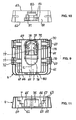
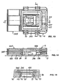
- the base 4 of the fastening device 1 is shown in FIGS. 8 to 11.
- the base 4 has essentially the shape of a cuboid and is symmetrical to the longitudinal center plane E. On its long sides, the base 4 is provided with reinforcing ribs 60, 61.
- the reinforcing ribs 60 are vertical and the reinforcing ribs 61 are aligned parallel to the bottom surface 62.
- the recess 7 has a bottom surface 65 and, in two planes lying above it, parallel step surfaces 66, 67, which are formed by lateral steps 68, 69 which widen the recess 7 towards the top 63 and parallel to the plane E.
- Grooves 70 are provided on the inside of the reinforcing ribs 60, which completely penetrate the base 4 in the area of the steps 68, 69 from the bottom surface 62 to the top 63.
- the grooves 70 have parallel side walls 71, 72. In the side walls 72, parallelepiped-shaped recesses are formed next to one another, which extend to the bottom surface 62 and at a distance from the step surfaces 66, 67 or from the top side 63, approximately parallel to these End surface 74 located halfway up the step.
- End surfaces 74 are visible in FIG.
- the recesses 73 are open to the recess 7 between the end surfaces 74 and the step surfaces 66, 67 or the bottom surface 65 which are adjacent to them and are respectively lower.
- a single recess with correspondingly positioned end faces and openings opening into the recess 7 can also be provided in the side walls 72.
- a wall 75 In the middle of the recess 7 there is a wall 75 at a distance from the steps 68, 69, which partially surrounds a fastening opening 76 in the bottom of the recess 7.
- the wall 75 carries a pawl 77, which is located above the opening. Opposite the pawl 77 are attached to the edge of the opening 76 guide webs 78 which limit a mounting opening 79 for receiving the T-bolt 10 with which the base 4 is fastened to the base 3.
- the pawl 77 deflects resiliently when the base 4 is attached to the T-bolt 10 and snaps back into its locked position as soon as the T-bolt 10 has snapped into the fastening opening 79. In its locked position, the pawl 77 locks the T-bolt 10 in the fastening opening 79, see FIG. 13
- FIGS. 8 and 11 there is an opening 81 in the rear end face 80 of the base 4, the width of which increases in two stages from top to bottom. Each step section is intended to receive the tongue of a holder. At the steps there are recesses 82 into which the snap hook attached to the end of the tongue can snap. A corresponding recess 83 is provided at the upper edge of the opening 81
- FIGS. 12 to 15 illustrate the connection of a plurality of holders 105, 205 and 305 to the base 4.
- the holders 105, 205 and 305 are approximately identical in construction to the holder 5 shown in FIGS. 2 and 3, but they differ from one another with regard to one another the width of their fastening areas, which are adapted to the distance between the opposing steps 68, 69 or the width of the upper opening of the recess 7.
- the fastening area 106 of the holder 105 has the smallest width and is intended for the arrangement between the steps 68.
- the holder 105 is inserted with its fastening area 106 into the recess 7 of the base 4 from above, the lateral projections 116 in the grooves 70 intervention.
- the fastening area 106 is in the recess 7 in a position in which the end of the tongue 117 lies within the recess 7.
- the holder 105 is displaced in the direction of the rear end face 80 of the base 4.
- the projections 116 enter the cutouts 73 and the tongue 117 penetrates with its snap hook 118 into the lowermost section of the opening 81, the tongue 117 resiliently deflecting downward.
- the end position is reached when the holding area 108, as shown in FIG. 12 , abuts on the front end face 64 of the base 4.
- the snap hook 118 engages in the recesses 82 at the opening 81 and thereby holds the holder 105 firmly in the base 4.
- the projections 116 are in this position in the recesses 73 below their end faces 74 and thereby secure the holder 105 in a form-fitting manner against lifting out of the recess 7.
- the holder 105 can be detached from the base 4 by pressing the snap hooks 118 out of the recesses 82 by pressure on the tongue 117 from above and at the same time the holder 105 is pulled forward on its holding region 108. As soon as the projections 116 are again in the grooves 70, the holder 105 can be removed upwards from the base 4 if there is no further holder.
- the holders 205 and 305 are also installed in the manner described above, the holder 205 with its fastening region 206 being arranged between the steps 69 and the holder 305 with its fastening region 306 in the opening of the recess 7.
- the width of the fastening areas 206 and 306 is correspondingly larger, the width of the tongues 217, 317 correspondingly smaller. From the different size ratios of the individual fastening areas, the person skilled in the art can therefore readily recognize the order in which the holders are to be assembled one after the other.
- FIG. 15 shows an application example in which only two holders 105 and 205 are inserted into the base 4.
- the holder for the holder 305 is empty.
- the step surfaces 67, on which the holder 305 is placed, the grooves 70 and the cutouts 73 for receiving the projections 316 can therefore be clearly seen
Landscapes
- Engineering & Computer Science (AREA)
- Architecture (AREA)
- Civil Engineering (AREA)
- Structural Engineering (AREA)
- Installation Of Indoor Wiring (AREA)
- Clamps And Clips (AREA)
- Connection Of Plates (AREA)
Abstract
Description
Die Erfindung betrifft eine Vorrichtung zum Befestigen von langgestreckten, flachen Gegenständen, insbesondere Flachbandleitungen, an einer Unterlage mit einem Halter, der einen Haltebereich mit Mitteln zum Festhalten wenigstens eines langgestreckten, flachen Gegenstands und einen Befestigungsbereich aufweist, der zum Befestigen des Halters bestimmt ist.The invention relates to a device for fastening elongated, flat objects, in particular ribbon cables, to a base with a holder which has a holding area with means for holding at least one elongated, flat object and a fastening area which is intended for fastening the holder.
Vorrichtungen der angegebenen Art werden zur Befestigung von elektrischen Flachbandleitungen beispielsweise an Karosserieteilen von Automobilen verwendet. Bei solchen Flachbandleitungen, auch Folienleiter oder Flachbandkabel genannt, sind eine Anzahl von Leiterbahnen nebeneinander auf einer dünnen, elektrisch isolierenden Trägerschicht aufgebracht und mit einer elektrisch isolierenden Deckschicht abgedeckt. Andere Ausführungen von Flachbandleitungen bestehen aus einer Mehrzahl von Leitern, die parallel zueinander angeordnet und von einem Isolator bedeckt sind, wobei sich zwischen benachbarten Leitern Verbindungsabschnitte des Isolators erstrecken. Bei der Verlegung von Flachbandleitungen ist es erforderlich, diese in Abständen an einer Unterlage zu befestigen.Devices of the type specified are used for fastening electrical ribbon cables, for example, to body parts of automobiles. In the case of such ribbon cables, also called film conductors or ribbon cables, a number of conductor tracks are applied next to one another on a thin, electrically insulating carrier layer and covered with an electrically insulating cover layer. Other designs of ribbon cables consist of a plurality of conductors which are arranged parallel to one another and covered by an insulator, with connecting sections of the insulator extending between adjacent conductors. When laying ribbon cables, it is necessary to attach them to a base at intervals.
Aus DE 101 29 833 A1 ist eine Klemme zum Halten eines Flachbandkabels bekannt, die ein U-förmiges Basisteil zum Aufnehmen des Flachbandkabels, ein mit dem Basisteil verbundenes Abdeckteil, einen sich von dem Basisteil erstrec??kenden Vorsprung und ein Andrückteil umfaßt, das an dem Abdeckteil angeordnet ist und das von dem Basisteil aufgenommene Flachbandkabel nach unten hält, wenn das Abdeckteil geschlossen ist. In dem Flachbandkabel ist ein Schlitz vorgesehen, in den der Vorsprung eindringt. Auf der Unterseite des Basisteils befindet sich ein Clip, der in ein Loch einer Automobilkarosserie einzusetzen ist, um das Flachbandkabel dort anzubringen.From DE 101 29 833 A1 a clamp for holding a ribbon cable is known, which comprises a U-shaped base part for receiving the ribbon cable, a cover part connected to the base part, a protrusion extending from the base part and a pressure part which presses on the cover part is arranged and holds the ribbon cable received by the base part downwards when the cover part is closed. A slot is provided in the ribbon cable into which the protrusion penetrates. There is a clip on the underside of the base part, which is to be inserted into a hole in an automobile body in order to attach the ribbon cable there.
Bei einer aus DE 100 51 120 A1 bekannten Vorrichtung zur Befestigung von Flachbandkabeln an einer Trägerplatte ragen von einer Grundplatte zwei elastisch spreizbare Fortsätze ab, deren Enden durch einen dreiteiligen Steg verbunden sind, dessen Gesamtlänge größer ist als der Abstand zwischen den beiden Fortsätzen und dessen drei Teile untereinander und mit den Enden der Fortsätze scharnierartig verbunden sind Die Grundplatte wird auf das an der Trägerplatte zu befestigende Flachbandkabel aufgesetzt und durch Niederdrücken des mittleren Teils des Steges werden die spreizbaren Fortsätze an auf der Trägerplatte angeordnete und durch Eingriffslocher in der Grundplatte hindurchragende Bolzen angedrückt und dadurch an der Grundplatte in dieser Lage fixiert.In a device known from DE 100 51 120 A1 for fastening ribbon cables to a carrier plate, two elastically expandable extensions protrude from a base plate, the ends of which are connected by a three-part web, the total length of which is greater than the distance between the two extensions and three of them Parts hinged to each other and to the ends of the extensions The base plate is placed on the ribbon cable to be fastened to the support plate and by pressing down the middle part of the web, the expandable extensions are pressed onto bolts arranged on the support plate and protruding through engagement holes in the base plate and thereby fixed to the base plate in this position.
Mit den bekannten Befestigungsvorrichtungen können auch mehrere Flachbandkabel übereinanderliegend befestigt werden. Da hierbei die Haltevorrichtung erst geschlossen werden kann, nachdem alle zu befestigenden Leitungen in sie eingelegt sind, müssen bei ungünstigen Einbaulagen, beispielsweise bei Überkopfanordnung besondere Hilfsmittel eingesetzt werden, um die unteren Lagen der Flachbandleitungen so lange zu halten, bis nach einlegen der obersten Lage die Vorrichtung geschlossen werden kann.With the known fastening devices, a plurality of ribbon cables can also be fastened one above the other. Since the holding device can only be closed after all the lines to be fastened have been inserted into it, special aids have to be used in unfavorable installation positions, for example in an overhead arrangement, in order to hold the lower layers of the ribbon cables until the top layer has been inserted Device can be closed.
Aus DE 100 45 765 D1 ist eine Umlenkvorrichtung für einen Folienleiter bekannt, die eine Umlenkklappe mit einer Umlenkkante und einer Schutzkante aufweist. Im Montagezustand ist der Folienleiter zwischen einer Grundklappe und der Umlenkklappe einerseits und zwischen der Umlenkkante und der Schutzkante andererseits eingeklemmt. Die Umlenkvorrichtung ermöglicht ein Umlenken des Folienleiters beispielsweise um 90° und dient gleichzeitig zu seiner Befestigung an einer Unterlage Hierzu weist die Umlenkvorrichtung an der Montageunterseite Befestigungselemente auf, die zum Einrasten in eine Öffnung eines Trägerteils bestimmt sind.DE 100 45 765 D1 discloses a deflection device for a film conductor, which has a deflection flap with a deflection edge and a protective edge. In the assembled state, the foil conductor is clamped between a base flap and the deflection flap on the one hand and between the deflection edge and the protective edge on the other hand. The deflection device enables the film conductor to be deflected, for example by 90 °, and at the same time serves for fastening it to a base.
Der Erfindung liegt die Aufgabe zugrunde, eine Vorrichtung zum Befestigen von langgestreckten, flachen Gegenständen, insbesondere Flachbandleitungen der eingangs genannten Art zu schaffen, die besonders einfach zu montieren und zu handhaben ist.The invention has for its object to provide a device for fastening elongated, flat objects, in particular ribbon cables of the type mentioned, which is particularly easy to assemble and handle.
Diese Aufgabe wird durch die im Patentanspruch 1 angegebene Erfindung gelöst. Vorteilhafte Ausgestaltungen der Erfindung sind in den Unteransprüchen angegeben.This object is achieved by the invention specified in claim 1. Advantageous embodiments of the invention are specified in the subclaims.
Nach der Erfindung weist die Vorrichtung einen Sockel auf, der getrennt von dem Halter an einer Unterlage beispielsweise an einer Automobilkarosserie, befestigbar ist, wobei an dem Sockel und an dem Befestigungsbereich des Halters einander zugeordnete Kupplungselemente vorgesehen sind, die zum Verbinden des Halters mit dem Sockel in eine Eingrifflage gebracht werden können, in welcher der Halter mit Hilfe der Kupplungselemente an dem Sockel festgehalten ist.According to the invention, the device has a base, which can be fastened separately from the holder on a base, for example on an automobile body, wherein associated coupling elements are provided on the base and on the fastening region of the holder, which are used to connect the holder to the base can be brought into an engagement position in which the holder is held on the base by means of the coupling elements.
Bei der erfindungsgemäßen Vorrichtung sind die Mittel, die mit der Flachbandleitung verbunden werden, nämlich der Halter, und die Mittel, die zur Befestigung an der Unterlage dienen, nämlich der Sockel, voneinander getrennt und können durch eine einfache, von Hand zu bedienende Kupplung fest miteinander verbunden werden Hierdurch ist es möglich, die zum Verlegen von Flachbandleitungen erforderlichen Vorgänge, nämlich das Anbringen der Flachbandleitung an der Befestigungsvorrichtung einerseits und das Anbringen der Befestigungsvorrichtung an der Unterlage andererseits zeitlich und räumlich getrennt voneinander durchzufuhren, um dann anschließend mit einem besonders einfachen Montagevorgang durch Zusammenfügen der Kupplungselemente die Flachbandleitung zu verlegen. Die Trennung der Montagevorgänge erweitert die Möglichkeiten zu ihrer Durchführung und erleichtert den Einsatz von Montagerobotern.In the device according to the invention, the means which are connected to the ribbon cable, namely the holder, and the means which are used for fastening to the base, namely the base, are separated from one another and can be firmly connected to one another by a simple, manually operated coupling This makes it possible to carry out the operations required for laying ribbon cables, namely the attachment of the ribbon cable to the fastening device on the one hand and the attachment of the fastening device to the support on the other hand, in terms of time and space, and then with a particularly simple assembly process by joining together of the coupling elements to lay the ribbon cable. The separation of the assembly processes expands the possibilities for their implementation and facilitates the use of assembly robots.
Ein weiterer Vorteil der erfindungsgemäßen Vorrichtung besteht darin, daß fur die Befestigung des Sockels an der Unterlage unterschiedliche Befestigungsmittel wie Bolzen, Schrauben, Nieten, Rastelemente oder Klebeverbindungen verwendet werden können, ohne daß diese Montageverfahren durch die vorherige Anbringung der Flachbandleitung behindert oder beeinträchtigt werden oder die Gefahr besteht, daß bei diesen Montagen die Flachbandleitung beschädigt wirdAnother advantage of the device according to the invention is that different fastening means such as bolts, screws, rivets, locking elements or adhesive connections can be used for fastening the base to the base without these assembly methods being hindered or impaired by the prior attachment of the ribbon cable or the There is a risk that the ribbon cable will be damaged during these assemblies
Der Sockel weist in einer bevorzugten Ausgestaltung eine Ausnehmung zur Aufnahme wenigstens eines Befestigungsbereichs eines Halters auf, wobei die Ausnehmung an wenigstens zwei gegenüberliegenden Seiten Kupplungselemente bildende Nuten und/oder Vorsprünge hat und der Befestigungsbereich des Halters mit den Nuten des Sockels zusammenwirkende Vorsprünge und/oder mit den Vorsprüngen des Sockels zusammenwirkende Nuten aufweist. Diese Gestaltung der Kupplungselemente ist einfach herstellbar und ermöglicht einfache Bewegungsabläufe bei der Montage.In a preferred embodiment, the base has a recess for receiving at least one fastening region of a holder, the recess having grooves and / or projections forming coupling elements on at least two opposite sides and the fastening region of the holder interacting with the grooves of the base and / or with the projections of the base have cooperating grooves. This design of the coupling elements is easy to manufacture and enables simple movements during assembly.
Vorzugsweise sind zueinander parallele Nuten in gegenüberliegenden Seitenwänden der Ausnehmung des Sockels ausgebildet und mit wenigstens einem offenen Ende versehen, wobei der Befestigungsbereich des Halters Vorsprünge hat, die in die Nuten eingreifen, wenn der Halter mit dem Sockel verbunden ist.Grooves which are parallel to one another are preferably formed in opposite side walls of the recess in the base and are provided with at least one open end, the fastening region of the holder having projections which engage in the grooves when the holder is connected to the base.
In einer bevorzugten Ausgestaltung wird der Halter mit seinem Befestigungsbereich auf der der Unterlage abgekehrten Seite des Sockels mit einer zur Unterlage hin gerichteten ersten Bewegung in die Ausnehmung des Sockels eingesetzt und dann durch eine quer zu dieser ersten Bewegung verlaufende zweite Bewegung in eine Eingriffstage gebracht, in welcher der Halter formschlüssig an dem Sockel befestigt ist Dieser Bewegungsablauf zum Verbinden von Halter und Sockel ist fur das Verlegen von Flachbandleitungen besonders günstig und ermöglicht eine einfache und leicht zu handhabende Gestaltung der Kupplungselemente.In a preferred embodiment, the holder, with its fastening area on the side of the base facing away from the base, is turned towards the base directional first movement inserted into the recess of the base and then brought by a second movement transverse to this first movement into an engagement day, in which the holder is positively attached to the base. This sequence of movements for connecting the holder and base is for laying ribbon cables particularly cheap and enables a simple and easy-to-use design of the coupling elements.
Für einen solchen Bewegungsablauf ist es zweckmäßig, wenn die Nuten eine seitliche Aussparung haben und die Vorsprünge des Halters in der mit dem Sockel verbundenen Eingriffslage an den seitlichen Aussparungen der Nuten angeordnet und dort abgestützt sind Mit dieser Gestaltung wird mit einfachen Mitteln eine formschlüssige Verriegelung zwischen Halter und Sockel in der Eingriffslage und eine wirksame Abstützung der Haltekräfte erreicht Die Fixierung des Befestigungsbereichs des Halters in der Eingriffslage kann vorteilhaft durch ein Schnappgesperre erfolgen, das einschnappt, sobald die Vorsprünge des Halters sich in der Eingriffslage an den seitlichen Aussparungen befinden.For such a sequence of movements, it is expedient if the grooves have a lateral recess and the projections of the holder are arranged on the lateral recesses of the grooves in the engagement position connected to the base and are supported there. With this design, a positive locking between the holder is achieved with simple means and base in the engagement position and an effective support of the holding forces is achieved. The fixing area of the holder in the engagement position can advantageously be fixed by a snap lock which snaps in as soon as the projections of the holder are in the engagement position on the lateral recesses.
Besonders vorteilhaft ist eine weitere Ausgestaltung der Erfindung, bei der die Ausnehmung des Sockels zwei oder mehr Abschnitte aufweist, die in parallelen Ebenen übereinander liegen, wobei jeder Abschnitt zur Aufnahme eines in seiner Größe dem jeweiligen Abschnitt angepaßten Befestigungsbereichs eines Halters ausgebildet ist Die Anschnitte können durch eine mehrstufige Ausbildung zweier gegenüber liegender Seitenwände der Ausnehmung voneinander abgesetzt sein Durch diese Gestaltung ist es möglich übereinander liegend mehrere Halter an ein und demselben Sockel zu befestigen, wobei jeder Halter wenigstens eine Flachbandleitung tragen kann Hierdurch können mehrere Flachbandleitungen übereinander liegend gehalten werden, wobei die Montage der einzelnen Leitungen unabhängig voneinander erfolgen kann und jede Leitung getrennt von den anderen mit ihrem Halter an dem Sockel befestigt ist. Zusätzliche Hilfsmittel zum Halten einzelner Leitungen während der Montage sind nicht erforderlich.A further embodiment of the invention is particularly advantageous, in which the recess in the base has two or more sections which lie one above the other in parallel planes, each section being designed to accommodate a fastening region of a holder which is adapted in size to the respective section a multi-stage design of two opposite side walls of the recess can be separated from one another.This design makes it possible to fasten several holders lying on top of one another on one and the same base, with each holder being able to carry at least one ribbon cable.This allows several ribbon cables to be held one above the other, the assembly of the individual lines can be done independently of each other and each line is attached to the base with its holder separately. Additional aids for holding individual lines during assembly are not required.
Zu seiner Befestigung an der Unterlage kann der Sockel eine Öffnung zur Aufnahme eines von der Unterlage abstehenden Befestigungsbolzens mit Hinterschnitt und den Hinterschnitt des Befestigungsbolzens eingreifende Haltemittel haben In einer anderen Ausgestaltung kann der Sockel an seiner der Unterlage zugewandten Unterseite mit einem in eine Offnung der Unterlage einsteckbaren Zapfen mit die Öffnung hintergreifenden Haltemitteln versehen sein.For its attachment to the base, the base can have an opening for receiving an attachment bolt projecting from the base with an undercut and retaining means engaging the undercut of the attachment bolt. In another embodiment, the base can have on its underside facing the base be provided with a pin which can be inserted into an opening of the base and which has holding means engaging behind the opening.
Eine bevorzugte Ausgestaltung des Halters umfaßt ein im wesentlichen plattenformiges Basisteil, das in nebeneinander liegender Anordnung den Haltebereich und den Befestigungsbereich bildet, wobei der Haltebereich eine Auflagefläche für einen langgestreckten, flachen Gegenstand, beiderseits der Auflageflache in Bezug auf diese erhabene Führungselemente und eine an dem Basisteil schwenkbar befestigte Klappe aufweist, die in einer an dem Basisteil festhaltbaren Verriegelungsstellung den auf der Anlagefläche angeordneten Gegenstand übergreift. Der Befestigungsbereich des Halters weist vorzugsweise an seinen gegenüber liegenden, an den Halterbereich angrenzenden Seiten zwei in einem Abstand voneinander angeordnete Vorsprünge auf, die zum Eingreifen in Nuten des Sockels bestimmt sind, und ist an seiner dem Haltebereich entgegen gesetzten Seite mit einer von dem Basisteil abstehenden, federnden Zunge versehen, die an ihrem freien Ende einen mit dem Sockel zusammenwirkenden Rasthaken trägt. Der Befestigungsbereich des Halters kann außerdem mit einer zentralen Öffnung versehen sein Durch diese Offnung wird ein bei der Anordnung des Halters im Sockel verfugbarer Freiraum geschaffen, der zur Anordnung eines der Befestigung des Sockels dienenden Mittels, beispielsweise eines Bolzens oder einer Schraube genutzt werden kann.A preferred embodiment of the holder comprises an essentially plate-shaped base part, which forms the holding area and the fastening area in an adjacent arrangement, the holding area forming a support surface for an elongated, flat object, on both sides of the support surface with respect to this raised guide elements and one on the base part has pivotally attached flap, which engages over the object arranged on the contact surface in a locking position that can be held on the base part. The fastening area of the holder preferably has on its opposite sides adjoining the holder area two projections which are arranged at a distance from one another and which are intended to engage in grooves in the base, and is on its side opposite the holding area with a protruding part from the base part provided resilient tongue, which carries at its free end a locking hook interacting with the base. The fastening area of the holder can also be provided with a central opening. This opening creates a free space which is available when the holder is arranged in the base and can be used to arrange a means for fastening the base, for example a bolt or a screw.
Die Klappe kann erfindungsgemäß mit dem Halter durch ein Filmscharnier verbunden sein. Eine andere vorteilhafte Ausgestaltung sieht vor, daß die Klappe zylindrische Lagerzapfen aufweist, die in eine teilzylindrische Lagerausnehmung in dem Halter einknöpfbar sind Hierbei ist es besonders vorteilhaft, wenn die Klappe vollkommen symmetrisch ausgebildet ist, so daß der Aufwand zur Positionierung der Klappe bei ihrer Montage minimal ist. Zur Verriegelung der Klappe in der Schließstellung kann an dem Halter oder an der Klappe ein Schnapphaken angebracht sein, der mit einem Vorsprung an der Klappe beziehungsweise an dem Halter zusammen wirkt Es ist auch von Vorteil, wenn die Klappe an der Scharnierseite Vorsprünge hat, die in der Schließstellung der Klappe in eine Ausnehmung des Halters eingreifen und die Klappe an dem Scharnier zusätzlich gegen Losen sichernAccording to the invention, the flap can be connected to the holder by a film hinge. Another advantageous embodiment provides that the flap has cylindrical journals that can be buttoned into a partially cylindrical bearing recess in the holder. It is particularly advantageous if the flap is completely symmetrical, so that the effort for positioning the flap during its assembly is minimal is. To lock the flap in the closed position, a snap hook can be attached to the holder or to the flap, which interacts with a projection on the flap or on the holder.It is also advantageous if the flap has projections on the hinge side that are in engage the closed position of the flap in a recess of the holder and additionally secure the flap on the hinge against loosening
Um den zwischen der Anlagefläche des Halters und der Klappe angeordneten, langgestreckten flachen Gegenstand mit einer definierten Kraft festzuspannen und an einer Verschiebung in Längsrichtung zu hindern, kann an der Klappe und/oder in der Anlagefläche des Halters eine erhabene Rippe aus einem weichelastischen Material vorgesehen sein. Vorzugsweise besteht die Rippe aus einem Einsatz, der in einen Schlitz des Halters beziehungsweise der Klappe eingesetzt ist Bei der Herstellung der Teile aus thermoplastischem Kunststoff ist es vorteilhaft, wenn die Rippe im Zweikomponenten-Spritzgießverfahren gemeinsam mit dem Halter beziehungsweise mit der Klappe hergestellt wird.In order to clamp the elongated flat object arranged between the contact surface of the holder and the flap with a defined force and to prevent displacement in the longitudinal direction, the flap and / or in the contact surface can be used of the holder, a raised rib made of a soft elastic material can be provided. The rib preferably consists of an insert which is inserted into a slot in the holder or the flap. When producing the parts from thermoplastic material, it is advantageous if the rib is produced together with the holder or with the flap in a two-component injection molding process.
Die erfindungsgemäße Vorrichtung eignet sich auch zum Umlenken von Flachbandleitungen, wenn die Klappe eine seitliche Umlenkkante aufweist, die in einem dem Umlenkwinkel entsprechenden Winkel zur Längsrichtung der Flachbandleitung verläuft. Zur Umlenkung wird die Flachbandleitung nach dem Schließen der Klappe um die Umlenkkante der Klappe herum gefaltet.The device according to the invention is also suitable for deflecting ribbon cables if the flap has a lateral deflection edge which runs at an angle corresponding to the deflection angle to the longitudinal direction of the ribbon cable. For deflection, the ribbon cable is folded around the deflection edge of the flap after the flap has been closed.
Die Erfindung wird nachfolgend anhand von Ausführungsbeispielen näher erläutert, die in der Zeichnung dargestellt sind. Es zeigen
- Figur 1
- eine perspektivische Darstellung einer Vorrichtung zum Halten dreier Flachbandleitungen,
- Figur 2
- eine Seitenansicht eines Halters der Vorrichtung gemäß Figur 1,
Figur 3- eine Draufsicht des Halters der Vorrichtung gemäß Figur 1,
Figur 4- eine zum Umlenken einer Flachbandleitung geeignete Ausführung eines Halters,
Figur 5- eine zweiteilige Ausführung eines Halters der erfindungsgemäßen Vorrichtung,
Figur 6- eine zweiteilige Ausführung eines Halters der erfindungsgemäßen Vorrichtung mit symmetrischer Klappe,
Figur 7- ein Querschnitt des Halters gemäß
Figur 6 entlang der Linie VII - VII, Figur 8- eine perspektivische Darstellung des Halters gemäß
Figur 6, - Figur 9
- eine Draufsicht einer Ausführungsform des Sockels der Vorrichtung gemäß Figur 1,
Figur 10- eine Rückansicht des Sockels gemäß Figur 9,
Figur 11- eine Vorderansicht des Sockels gemäß Figur 9,
Figur 12- eine Ansicht des Sockels gemäß Figur 9 von unten,
Figur 13- eine Draufsicht der Vorrichtung gemäß Figur 1,
Figur 14- einen Längsschnitt der Vorrichtung gemäß Figur 1 entlang der Linie A - A in
Figur 13, Figur 15- einen Querschnitt der Vorrichtung gemäß Figur 1 entlang der Linie B - B in
Figur 13 und Figur 16- eine perspektivische Darstellung der mit zwei Haltern bestückten Vorrichtung gemäß Figur 1.
- Figure 1
- 1 shows a perspective illustration of a device for holding three ribbon cables,
- Figure 2
- 2 shows a side view of a holder of the device according to FIG. 1,
- Figure 3
- 2 shows a top view of the holder of the device according to FIG. 1,
- Figure 4
- an embodiment of a holder suitable for deflecting a ribbon cable,
- Figure 5
- a two-part design of a holder of the device according to the invention,
- Figure 6
- a two-part design of a holder of the device according to the invention with a symmetrical flap,
- Figure 7
- 6 shows a cross section of the holder according to FIG. 6 along the line VII-VII,
- Figure 8
- 6 shows a perspective illustration of the holder according to FIG. 6,
- Figure 9
- 2 shows a top view of an embodiment of the base of the device according to FIG. 1,
- Figure 10
- 5 shows a rear view of the base according to FIG. 9,
- Figure 11
- 6 shows a front view of the base according to FIG. 9,
- Figure 12
- 9 shows a view of the base according to FIG. 9 from below,
- Figure 13
- 2 shows a top view of the device according to FIG. 1,
- Figure 14
- 2 shows a longitudinal section of the device according to FIG. 1 along the line AA in FIG. 13,
- Figure 15
- a cross section of the device of Figure 1 along the line B - B in Figure 13 and
- Figure 16
- 2 shows a perspective illustration of the device according to FIG. 1 equipped with two holders.
Figur 1 zeigt eine Befestigungsvorrichtung 1, die zum Befestigen von mehreren Flachbandleitungen 2 an einer Unterlage 3, beispielsweise der Karosserie eines Automobils bestimmt ist. Die Befestigungsvorrichtung 1 umfaßt einen Sockel 4 und mehrere Halter 5, die übereinander angeordnet und mit ihren Befestigungsbereichen 6 in einer zentralen Ausnehmung 7 des Sockels 4 befestigt sind. Jeder Halter 5 hat einen sich außerhalb des Sockels 4 erstreckenden Haltebereich 8, an dem die Flachbandleitung 2 mittels einer verschließbaren Klappe 9 festgehalten ist. Der Sockel 4 ist an der Unterlage 3 mit Hilfe eines T-Bolzens 10 befestigt, der in eine Öffnung des Sockels 4 eingeknöpft ist.FIG. 1 shows a fastening device 1 which is intended for fastening a plurality of ribbon cables 2 to a
Wie aus den Figuren 2 und 3 zu ersehen, hat der Halter 5 ein Basisteil 11 in Form einer im wesentlichen ebenen Platte, die in einen rechteckigen Haltebereich 8 und einen Befestigungsbereich 6 gegliedert ist Der Befestigungsbereich 6 hat die Form eines Rahmens mit einer zentralen Öffnung 12, zwei kürzeren Rahmenschenkeln 13, 14 und zwei längeren Rahmenschenkeln 15 Die beiden längeren Rahmenschenkel 15 tragen in symmetrischer Anordnung auf ihrer Außenseite jeweils zwei noppenartige Vorsprunge 16, die zur Abstutzung des Halters 5 an dem Sockel 4 dienen Der kürzere Rahmenschenkel 13, der von dem Befestigungsbereich 6 weiter entfernt ist, weist auf seiner Außenseite eine sich parallel zur Rahmenebene erstreckende federnde Zunge 17 auf, die an ihrem freien Ende einen Schnapphaken 18 trägt, wobei die Sperrfläche 19 des Schnapphakens 18 dem Rahmenschenkel 13 zugewandt istAs can be seen from FIGS. 2 and 3, the
An den kürzeren Rahmenschenkel 14 des Befestigungsbereichs 6 schließt sich der Haltebereich 8 an, der in Verlängerung der Rahmenschenkel 15 zwei Schenkel 20 mit in einer gemeinsamen Ebene liegenden Anlageflächen 21 aufweist. Die Schenkel 20 sind durch eine Öffnung 22 voneinander getrennt und ihre dem Rahmenschenkel 14 entgegengesetzte Enden sind durch einen Schenkel 23 miteinander verbunden. Über der Öffnung 22 befindet sich eine Klappe 24, die mit Hilfe eines Biegescharniers 25 schwenkbar an dem Schenkel 14 befestigt ist. Die Öffnung 22 ist vorgesehen, um den Halter in einem einfachen Formwerkzeug, welches keinen Schieber aufweist, herstellen zu können Das freie Ende der Klappe 24 ist mit einer Schnappnase 26 versehen, die zur Arretierung der Klappe 24 in der Schließstellung einen der Öffnung 22 zugekehrten Abschnitt des Schenkels 23 untergreift. Der Schenkel 23 bildet mit sich entlang der Anlageflächen 21 erstreckenden Verlangerungen eine durchgehende Rippe 27, die von den Anlageflächen 21 absteht und eine seitliche Anlage zur Führung und Abstützung einer auf den Anlageflächen 21 angeordneten Flachbandleitung bildet. In einem Abstand von der Rippe 27 und parallel zu dieser sind an den Schenkeln 20, Rippen 28 vorgesehen, die ebenfalls von der jeweiligen Anlagefläche 21 abstehen und eine der Rippe 27 gegenüberliegende seitliche Anlage fur die Flachbandleitung bilden.The
Um eine Flachbandleitung an dem Halter 5 zu befestigen, wird diese bei geöffneter Klappe 24 auf die Anlageflächen 21 aufgelegt. Anschließend wird die Klappe 24 geschlossen und mit Hilfe der Rastnase 26 an dem Schenkel 23 fixiert. Die Flachbandleitung wird auf diese Weise vollständig von dem Haltebereich 8 des Halters 5 umgriffen und dadurch zuverlässig mit dem Halter 5 verbunden.In order to attach a ribbon cable to the
Figur 4 zeigt einen Halter 29, der sich von dem Halter 5 durch eine Abwandlung seines Haltebereichs 30 unterscheidet und der zum Umlenken einer Flachbandleitung geeignet ist. Der Befestigungsbereich des Halters 29 stimmt mit demjenigen des Halters 5 überein. Der Haltebereich 30 hat eine trapezförmige Klappe 31, die über einer trapezförmigen Öffnung 32 angeordnet ist. Die kurze Parallelseite der Klappe 31 ist durch ein Biegescharnier 33 mit dem Rahmenschenkel 14 des Befestigungsbereichs 6 verbunden. Die lange Parallelseite der Klappe 31 ist mit einer Schnappleiste 34 versehen, die in eine Ausnehmung des äußeren Schenkels 35 des Haltebereiches 30 einschnappt, um die Klappe 31 in der in der Zeichnung gezeigten Schließstellung zu halten. Die Seitenkanten 36 der Klappe 31 sind in einem Winkel von 45° zur Längsachse des Schenkels 35 geneigt.FIG. 4 shows a
Eine in den Haltebereich 30 eingelegte und von der geschlossenen Klappe 31 festgehaltene Flachbandleitung kann durch Umfalten an einer der Seitenkanten 36 in einem Winkel von 90° umgelenkt werden Wird die Flachbandleitung an beiden Seitenkanten 36 umgefaltet, so ergibt sich eine Umlenkung der Flachbandleitung um 180°. Die auf beiden Seiten der Öffnung 32 befindlichen Schenkel 37 des Haltebereichs 30 dienen der Führung und Abstützung der Flachbandleitung, wenn diese nicht umgelenkt wird. Bei Umlenkung bilden sie aufgrund ihres Überstandes einen seitlichen Schutz für die umgefaltete Kante der FlachbandleitungA ribbon cable inserted into the holding
Figur 5 zeigt einen Halter 38 mit einer getrennt von dem Halter 38 hergestellten und anschließend mit diesem beweglich verbundenen Klappe 39. Das Basisteil 40 weist hierbei im Haltebereich eine geschlossene, sich unter der Klappe 39 hindurch erstreckende Platte 41 auf, die an ihrer an den Halter 5 angrenzenden, verstärkten Längsseite zwei im Abstand voneinander angeordnete Lagernuten 42 hat. In den Lagernuten 42 sind an einem Ende der Klappe 39 angeordnete, zylindrische Lagerzapfen 43 gelagert. Die Lagerzapfen 43 greifen mit mehr als der Hälfte ihres Umfangs in die Lagernuten 42 ein Die Öffnungsweite der Lagernuten 42 ist kleiner als der Durchmesser der Lagerzapfen, so daß die Lagerzapfen formschlüssig in den Lagernuten 42 gehalten sind. Die Öffnung der Lagernuten 42 ist andererseits ausreichend groß, um unter Ausnutzung der werkstoffbedingten elastischen Verformbarkeit der Lagernuten 42 ein Einknöpfen der Lagerzapfen 43 in dieselben zu ermöglichen.FIG. 5 shows a
In der Schließstellung ist die Klappe 39 an ihrer durch die Lagerzapfen 43 gebildeten Schwenkachse zusätzlich durch eine Rippe 44 gegen Lösen gesichert, die sich am Basisteil 40 in der Mitte zwischen den Lagernuten 42 befindet und in eine Ausnehmung 45 auf der Oberseite der Klappe 39 eingreift. Bei vollständig geöffneter Klappe 39 ist der Rand der Ausnehmung 45 so weit von der Rippe 44 entfernt, daß das Einsetzen der Klappe 39 in die Lagernuten 42 durch die Rippe 44 nicht behindert wird.In the closed position, the
Wie bei den anderen, bereits beschriebenen Haltern wird auch die Klappe 39 durch einen mit einer Rastnase an ihrem freien Ende zusammenwirkenden Schnappverschluß 46 in der Schließstellung gehalten, der an einem elastisch verformbaren Schenkel 47 des Basisteils 40 ausgebildet istAs with the other holders already described, the
Bei der in den Figuren 6 bis 8 gezeigten Ausgestaltung eines Halters 48 ist die getrennt von dem Basisteil 49 hergestellte Klappe 50 vollkommen symmetrisch ausgebildet Hierdurch wird die Lageausrichtung der Klappe 50 vor der Montage vereinfacht und eine automatische Montage der Klappe 50 erleichtert Wie bei dem Halter gemäß Figur 5 weist die Klappe 50 Lagerzapfen 43a, 43b auf, die in Lagernuten 42a, 42b im Basisteil 49 einknöpfbar sind. Da die Klappe 50 infolge ihrer symmetrischen Gestaltung vier Lagerzapfen hat, ist auch das Basisteil 49 mit vier den Lagerzapfen zugeordneten Lagernuten versehen. Hierbei dienen die den Befestigungsbereich 6 benachbarten Lagernuten 42a und Lagerzapfen 43a der Schwenklagerung der Klappe 50, während die am freien Ende des Haltebereiches 51 befindlichen Lagernuten 42b lediglich zum Festhalten der Lagerzapfen 43b und damit auch der Klappe 50 in der Schließstellung dienen Zusätzlich ist die Klappe 50 in der Schließstellung durch eine federnde Raste 52 gesichert, die an den freien Enden des Haltebereiches 51 angebracht ist und eine Leiste 53 übergreift, die sich längs des Randes der Klappe 50 erstreckt Die Leiste 53 hat zwei Vorsprünge 54, die beiderseits der Raste 52 in Ausnehmungen 55 im Basisteil 49 eingreifen Auf der anderen, als Schwenklager dienenden Seite der Klappe 50 untergreifen die dort in der Zeichnung nicht sichtbaren Vorsprünge 54 einen sich zwischen den Lagernuten 42 erstreckenden Abschnitt 56 des Basisteils 49 und verhindert dadurch, daß sich die Schwenklagerseite der Klappe 50 vom Basisteil 49 lösen kann.In the embodiment of a
Um die Flachbandleitung mit einer definierten Anpreßkraft im Haltebereich 51 festzuspannen und an einer Verschiebung in Längsrichtung zu hindern, sind, wie insbesondere aus Figur 7 zu ersehen, in der Klappe 50 und in dem von der Klappe 50 überdeckten Basisteil 49 Einsätze 57, 58 aus weichelastischem Material, z.B. Gummi oder TPE angeordnet Die Einsätze 57, 58 erstrecken sich quer zur Längsrichtung der festzuspannenden Flachbandleitung über die gesamte Breite der Anlagefläche der Klappe 50 und des Basisteils 49. Die Einsätze 57, 58 sind in Schlitzen der Klappe 50 bzw des Basisteils 49 angeordnet und ragen auf beiden Seiten der Klappe 50 bzw des Basisteils 49 mit einer leicht gewolbten Oberfläche aus diesen heraus. An ihren in den Schlitzen befindlichen Längsseiten sind die Einsätze 56, 57 genutet und durch in die Nuten eingreifende Federn 59 der Klappe 50 bzw. des Basisteils 49 formschlüssig gehalten An der Klappe 50 befindet sich der Einsatz 57 aus Symmetriegründen in der Mitte Im Basisteil 49 sind zwei Einsätze 58 im gleichen Abstand von der Mitte angeordnet Je nach Dicke der Flachbandleitung werden beim Schließen der Klappe 50 die Einsatze 57, 58 mehr oder weniger stark in die Schlitze hineingedrückt, wobei sie mit einer definierten Kraft auf die Flachbandleitung einwirken und diese reibschlüssig in dem Halter fixieren.In order to clamp the ribbon cable with a defined contact pressure in the holding
Der Sockel 4 der Befestigungsvorrichtung 1 ist in den Figuren 8 bis 11 dargestellt. Der Sockel 4 hat im wesentlichen die Form eines Quaders und ist zur Längsmittelebene E symmetrisch ausgebildet. An seinen Längsseiten ist der Sockel 4 mit Verstärkungsrippen 60, 61 versehen. Die Verstärkungsrippen 60 sind senkrecht und die Verstärkungsrippen 61 parallel zur Bodenfläche 62 ausgerichtet Im Sockel 4 befindet sich eine Ausnehmung 7, die an der Oberseite 63 und an der vorderen Stirnseite 64 offen ist. Die Ausnehmung 7 hat eine Bodenfläche 65 und in zwei daruberliegenden Ebenen zu dieser parallele Stufenflächen 66, 67, die von seitlichen, die Ausnehmung 7 zur Oberseite 63 hin erweiternden und zur Ebene E parallelen Stufen 68, 69 gebildet sind. Auf der Innenseite der Verstärkungsrippen 60 sind Nuten 70 vorgesehen, die den Sockel 4 im Bereich der Stufen 68, 69 von der Bodenfläche 62 bis zur Oberseite 63 vollständig durchdringen. Die Nuten 70 haben parallele Seitenwände 71, 72. In den Seitenwänden 72 sind nebeneinander quaderförmige Aussparungen ausgebildet, die sich bis zur Bodenfläche 62 erstrecken und jeweils in einem Abstand von den Stufenflächen 66, 67 bzw. von der Oberseite 63 eine zu diesen parallele, etwa auf halber Stufenhöhe liegende Endfläche 74 haben In Figur 11 sind die Endflächen 74 sichtbar. Zwischen den Endflächen 74 und den diesen benachbarten, jeweils tiefer liegenden Stufenflächen 66, 67 bzw. der Bodenfläche 65 sind die Aussparungen 73 zur Ausnehmung 7 hin offen. Anstelle mehrerer nebeneinanderliegender Aussparungen 73 kann in den Seitenwänden 72 auch eine einzige Aussparung mit entsprechend positionierten Endflächen und in die Ausnehmung 7 mündenden Öffnungen vorgesehen sein.The
In der Mitte der Ausnehmung 7 befindet sich in einem Abstand von den Stufen 68, 69 eine Wand 75, die eine Befestigungsöffnung 76 im Boden der Ausnehmung 7 teilweise umgibt. Die Wand 75 trägt eine Sperrklinke 77, die sich über der Öffnung befindet. Gegenüber der Sperrklinke 77 sind an dem Rand der Öffnung 76 befestigte Führungsstege 78 angebracht, die eine Befestigungsöffnung 79 zur Aufnahme des T-Bolzens 10 begrenzen, mit dem der Sockel 4 an der Unterlage 3 befestigt ist. Die Sperrklinke 77 weicht beim Aufstecken des Sockels 4 auf den T-Bolzen 10 federnd aus und schnappt in ihre Sperrstellung zuruck, sobald der T-Bolzen 10 in die Befestigungsöffnung 79 eingerastet ist. In ihrer Sperrstellung verriegelt die Sperrklinke 77 den T-Bolzen 10 in der Befestigungsöffnung 79, siehe Figur 13In the middle of the
Wie aus den Figuren 8 und 11 zu ersehen, befindet sich in der hinteren Stirnseite 80 des Sockels 4 eine Öffnung 81, deren Breite in zwei Stufen von oben nach unten zunimmt. Jeder Stufenabschnitt ist zur Aufnahme der Zunge eines Halters bestimmt. An den Stufen befinden sich Ausnehmungen 82, in die der am Ende der Zunge angebrachte Schnapphaken einrasten kann. Eine entsprechende Ausnehmung 83 ist am oberen Rand der Öffnung 81 vorgesehenAs can be seen from FIGS. 8 and 11, there is an
In den Figuren 12 bis 15 ist die Verbindung von mehreren Haltern 105, 205 und 305 mit dem Sockel 4 veranschaulicht Die Halter 105, 205 und 305 sind annähernd baugleich mit dem in den Figuren 2 und 3 gezeigten Halter 5. Sie unterscheiden sich jedoch voneinander hinsichtlich der Breite ihrer Befestigungsbereiche, die an den Abstand der einander gegenuberliegenden Stufen 68, 69 bzw. Breite der oberen Öffnung der Ausnehmung 7 angepaßt sind. Der Befestigungsbereich 106 des Halters 105 hat die geringste Breite und ist für die Anordnung zwischen den Stufen 68 bestimmt Zur Montage wird der Halter 105 mit seinem Befestigungsbereich 106 von oben in die Ausnehmung 7 des Sockels 4 eingelegt, wobei die seitlichen Vorsprünge 116 in die Nuten 70 eingreifen. Bei diesem Vorgang befindet sich der Befestigungsbereich 106 in der Ausnehmung 7 in einer Position, in der das Ende der Zunge 117 innerhalb der Ausnehmung 7 liegt. Sobald der Befestigungsbereich 106 auf der Bodenfläche 65 aufliegt, wird der Halter 105 in Richtung der hinteren Stirnseite 80 des Sockels 4 verschoben. Hierbei gelangen die Vorsprünge 116 in die Aussparungen 73 und die Zunge 117 dringt mit ihrem Schnapphaken 118 in den untersten Abschnitt der Öffnung 81 ein, wobei die Zunge 117 federnd nach unten ausweicht Die Endstellung ist erreicht, wenn der Haltebereich 108, wie in Figur 12 gezeigt, an der vorderen Stirnseite 64 des Sockels 4 anstößt. In dieser Stellung rastet der Schnapphaken 118 in die Ausnehmungen 82 an der Öffnung 81 ein und halt dadurch den Halter 105 in dem Sockel 4 fest. Die Vorsprunge 116 befinden sich in dieser Stellung in den Aussparungen 73 unter deren Endflächen 74 und sichern dadurch den Halter 105 formschlussig gegen Herausheben aus der Ausnehmung 7.FIGS. 12 to 15 illustrate the connection of a plurality of
Der Halter 105 kann von dem Sockel 4 gelöst werden, indem durch einen Druck von oben auf die Zunge 117 der Schnapphaken 118 aus den Ausnehmungen 82 herausgedrückt und gleichzeitig der Halter 105 an seinem Haltebereich 108 nach vorne gezogen wird Sobald sich die Vorsprünge 116 wieder in den Nuten 70 befinden, kann der Halter 105 nach oben aus dem Sockel 4 entnommen werden, wenn kein weiterer Halter vorhanden ist.The
Die Montage der Halter 205 und 305 erfolgt ebenfalls in der vorstehend beschriebenen Weise, wobei der Halter 205 mit seinem Befestigungsbereich 206 zwischen den Stufen 69 und der Halter 305 mit seinem Befestigungsbereich 306 in der Öffnung der Ausnehmung 7 angeordnet wird. Die Breite der Befestigungsbereiche 206 und 306 ist entsprechend größer, die Breite der Zungen 217, 317 entsprechend kleiner. An den unterschiedlichen Größenverhältnissen der einzelnen Befestigungsbereiche kann der Fachmann daher ohne weiteres erkennen, in welcher Reihenfolge die Halter nacheinander zu montieren sind.The
Figur 15 zeigt ein Anwendungsbeispiel, bei dem lediglich zwei Halter 105 und 205 in den Sockel 4 eingesetzt sind. Die Aufnahme für den Halter 305 ist leer. Man kann daher die Stufenflächen 67, auf die der Halter 305 aufgelegt wird, die Nuten 70 und die Aussparungen 73 zur Aufnahme der Vorsprünge 316 gut erkennenFIG. 15 shows an application example in which only two
Claims (22)
Applications Claiming Priority (2)
| Application Number | Priority Date | Filing Date | Title |
|---|---|---|---|
| DE10312015A DE10312015B4 (en) | 2003-03-18 | 2003-03-18 | Fastening device for elongate, flat objects, in particular ribbon cables |
| DE10312015 | 2003-03-18 |
Publications (2)
| Publication Number | Publication Date |
|---|---|
| EP1460322A1 true EP1460322A1 (en) | 2004-09-22 |
| EP1460322B1 EP1460322B1 (en) | 2010-05-05 |
Family
ID=32797958
Family Applications (1)
| Application Number | Title | Priority Date | Filing Date |
|---|---|---|---|
| EP04005931A Expired - Fee Related EP1460322B1 (en) | 2003-03-18 | 2004-03-12 | Fixing device for flat, elongated elements, in particular for flat cables |
Country Status (5)
| Country | Link |
|---|---|
| US (1) | US7048592B2 (en) |
| EP (1) | EP1460322B1 (en) |
| JP (1) | JP2004282994A (en) |
| DE (2) | DE10312015B4 (en) |
| ES (1) | ES2342164T3 (en) |
Cited By (1)
| Publication number | Priority date | Publication date | Assignee | Title |
|---|---|---|---|---|
| EP1717453A1 (en) * | 2005-04-27 | 2006-11-02 | Newfrey LLC | Clip and fastening system with a clip |
Families Citing this family (2)
| Publication number | Priority date | Publication date | Assignee | Title |
|---|---|---|---|---|
| JP2008186706A (en) * | 2007-01-30 | 2008-08-14 | Fujikura Ltd | Connector for flat harness |
| US7976333B2 (en) | 2009-09-29 | 2011-07-12 | Flex-Cable | Laminar electrical connector |
Citations (4)
| Publication number | Priority date | Publication date | Assignee | Title |
|---|---|---|---|---|
| JPH11122759A (en) | 1997-10-17 | 1999-04-30 | Fujikura Ltd | Clip for flat cable |
| DE10129833A1 (en) | 2000-06-21 | 2002-02-14 | Yazaki Corp | Clamp for holding clip onto flat cable has projection extending from bottom of base in same direction as side walls, being fitted into slit formed through or notched in flat cable |
| DE10051120A1 (en) | 2000-10-14 | 2002-04-25 | Raymond A & Cie | Device for retaining and/or fixing of flat objects, especially ribbon cable for motor vehicle bodywork parts, includes base plate from which extend two elastically splayed extensions, the ends of which are joined via a three-part web |
| DE10045765C1 (en) | 2000-09-15 | 2002-05-02 | Leoni Bordnetz Sys Gmbh & Co | Deflection device for a ribbon cable |
Family Cites Families (7)
| Publication number | Priority date | Publication date | Assignee | Title |
|---|---|---|---|---|
| US3715705A (en) * | 1971-03-29 | 1973-02-06 | Thomas & Betts Corp | Multicompartment connector |
| CH549988A (en) * | 1972-06-16 | 1974-06-14 | Bratschi Silent Gliss | FASTENING DEVICE. |
| US4356799A (en) * | 1978-04-19 | 1982-11-02 | Eaton Corporation | Spring retainer-valve selector |
| US4913656A (en) * | 1989-04-07 | 1990-04-03 | Rogers Corporation | Electrical connector |
| US5151560A (en) * | 1990-12-10 | 1992-09-29 | Amp Incorporated | Grounding connector |
| US5817983A (en) * | 1997-02-25 | 1998-10-06 | Raychem Corporation | arrangement for holding elongate substrates |
| US6771516B1 (en) * | 1999-12-27 | 2004-08-03 | Micron Technology, Inc. | Method and apparatus for fastening circuit boards to computer chassis |
-
2003
- 2003-03-18 DE DE10312015A patent/DE10312015B4/en not_active Expired - Fee Related
-
2004
- 2004-03-11 JP JP2004069070A patent/JP2004282994A/en not_active Ceased
- 2004-03-12 ES ES04005931T patent/ES2342164T3/en not_active Expired - Lifetime
- 2004-03-12 EP EP04005931A patent/EP1460322B1/en not_active Expired - Fee Related
- 2004-03-12 DE DE502004011115T patent/DE502004011115D1/en not_active Expired - Lifetime
- 2004-03-17 US US10/801,677 patent/US7048592B2/en not_active Expired - Fee Related
Patent Citations (4)
| Publication number | Priority date | Publication date | Assignee | Title |
|---|---|---|---|---|
| JPH11122759A (en) | 1997-10-17 | 1999-04-30 | Fujikura Ltd | Clip for flat cable |
| DE10129833A1 (en) | 2000-06-21 | 2002-02-14 | Yazaki Corp | Clamp for holding clip onto flat cable has projection extending from bottom of base in same direction as side walls, being fitted into slit formed through or notched in flat cable |
| DE10045765C1 (en) | 2000-09-15 | 2002-05-02 | Leoni Bordnetz Sys Gmbh & Co | Deflection device for a ribbon cable |
| DE10051120A1 (en) | 2000-10-14 | 2002-04-25 | Raymond A & Cie | Device for retaining and/or fixing of flat objects, especially ribbon cable for motor vehicle bodywork parts, includes base plate from which extend two elastically splayed extensions, the ends of which are joined via a three-part web |
Non-Patent Citations (1)
| Title |
|---|
| PATENT ABSTRACTS OF JAPAN vol. 1999, no. 09 30 July 1999 (1999-07-30) * |
Cited By (2)
| Publication number | Priority date | Publication date | Assignee | Title |
|---|---|---|---|---|
| EP1717453A1 (en) * | 2005-04-27 | 2006-11-02 | Newfrey LLC | Clip and fastening system with a clip |
| US7401387B2 (en) | 2005-04-27 | 2008-07-22 | Newfrey Llc | Clip for joining structural parts and fastening systems using a clip |
Also Published As
| Publication number | Publication date |
|---|---|
| EP1460322B1 (en) | 2010-05-05 |
| DE10312015B4 (en) | 2006-10-19 |
| JP2004282994A (en) | 2004-10-07 |
| DE502004011115D1 (en) | 2010-06-17 |
| DE10312015A1 (en) | 2004-10-07 |
| US7048592B2 (en) | 2006-05-23 |
| US20040235362A1 (en) | 2004-11-25 |
| ES2342164T3 (en) | 2010-07-02 |
Similar Documents
| Publication | Publication Date | Title |
|---|---|---|
| DE3432302C2 (en) | Clamp for electrical cable bundles | |
| DE10340571B3 (en) | Clamp for holding flat objects | |
| DE2914317C2 (en) | Connector device | |
| DE2544893A1 (en) | ELECTRICAL CONNECTION ELEMENT FOR A CLAMPING CONNECTION AND AN ELECTRICAL CONNECTION | |
| EP2132841B1 (en) | Snap fastener for fastening a housing | |
| EP3843221A1 (en) | Supporting frame for a connector | |
| DE102009019337B4 (en) | Modular holding device for mounted within an aircraft fuselage attachments | |
| DE102006059863B3 (en) | Electrical or electronic device e.g. signal converter, fastening device for use in e.g. system engineering, has carrier plate with projection that is arranged corresponding to spring tab, and snap-in hooks that are bent against edge of rail | |
| EP0528371B1 (en) | Cabinet suitable for wall or floor mounting | |
| DE10243383B3 (en) | Electrical installation device carrier rail fixing uses spring-loaded slider with retention nose secured to housing of installation device | |
| DE202017100200U1 (en) | Divider for energy supply chains | |
| EP1460322B1 (en) | Fixing device for flat, elongated elements, in particular for flat cables | |
| EP0752745A1 (en) | Metallic installation channel opened on one side | |
| EP0139980B1 (en) | Collier de câble | |
| DE69836574T2 (en) | Electric box | |
| DE102020126444B4 (en) | Cable bushing with a base frame and with a plurality of cable bushing modules and method for their assembly | |
| DE4331580C1 (en) | Flush-mounted box for electrical installation apparatuses | |
| DE102019112612B3 (en) | Holding frame and connector with such a holding frame | |
| DE19502681A1 (en) | Strain relief and fastener | |
| EP0722208A2 (en) | Device for flushmounting an electrical installation apparatus | |
| EP0645851B1 (en) | Busline connector and busline | |
| EP0917751B1 (en) | Device for connecting an item of electrical switchgear to a busbar and a mounting rail | |
| DE19546504C2 (en) | Switching arrangement with at least two flat, electrical guide strips | |
| DE102006051830A1 (en) | Retainer for elongated articles e.g. pipes, has square body with side sections formed with slots for receiving coupling elements, in which slots form open channels extending between rear edge areas of slots and major surfaces of square body | |
| EP3618208A1 (en) | Cable tray and device for connecting cable trays |
Legal Events
| Date | Code | Title | Description |
|---|---|---|---|
| PUAI | Public reference made under article 153(3) epc to a published international application that has entered the european phase |
Free format text: ORIGINAL CODE: 0009012 |
|
| AK | Designated contracting states |
Kind code of ref document: A1 Designated state(s): AT BE BG CH CY CZ DE DK EE ES FI FR GB GR HU IE IT LI LU MC NL PL PT RO SE SI SK TR |
|
| AX | Request for extension of the european patent |
Extension state: AL LT LV MK |
|
| 17P | Request for examination filed |
Effective date: 20050303 |
|
| AKX | Designation fees paid |
Designated state(s): DE ES FR GB IT |
|
| 17Q | First examination report despatched |
Effective date: 20081016 |
|
| GRAP | Despatch of communication of intention to grant a patent |
Free format text: ORIGINAL CODE: EPIDOSNIGR1 |
|
| GRAS | Grant fee paid |
Free format text: ORIGINAL CODE: EPIDOSNIGR3 |
|
| GRAA | (expected) grant |
Free format text: ORIGINAL CODE: 0009210 |
|
| AK | Designated contracting states |
Kind code of ref document: B1 Designated state(s): DE ES FR GB IT |
|
| REG | Reference to a national code |
Ref country code: GB Ref legal event code: FG4D Free format text: NOT ENGLISH |
|
| REF | Corresponds to: |
Ref document number: 502004011115 Country of ref document: DE Date of ref document: 20100617 Kind code of ref document: P |
|
| REG | Reference to a national code |
Ref country code: ES Ref legal event code: FG2A Ref document number: 2342164 Country of ref document: ES Kind code of ref document: T3 |
|
| PLBE | No opposition filed within time limit |
Free format text: ORIGINAL CODE: 0009261 |
|
| STAA | Information on the status of an ep patent application or granted ep patent |
Free format text: STATUS: NO OPPOSITION FILED WITHIN TIME LIMIT |
|
| 26N | No opposition filed |
Effective date: 20110208 |
|
| REG | Reference to a national code |
Ref country code: DE Ref legal event code: R097 Ref document number: 502004011115 Country of ref document: DE Effective date: 20110207 |
|
| PGFP | Annual fee paid to national office [announced via postgrant information from national office to epo] |
Ref country code: FR Payment date: 20120406 Year of fee payment: 9 |
|
| PGFP | Annual fee paid to national office [announced via postgrant information from national office to epo] |
Ref country code: GB Payment date: 20120326 Year of fee payment: 9 Ref country code: IT Payment date: 20120323 Year of fee payment: 9 |
|
| PGFP | Annual fee paid to national office [announced via postgrant information from national office to epo] |
Ref country code: ES Payment date: 20120326 Year of fee payment: 9 |
|
| GBPC | Gb: european patent ceased through non-payment of renewal fee |
Effective date: 20130312 |
|
| REG | Reference to a national code |
Ref country code: FR Ref legal event code: ST Effective date: 20131129 |
|
| PG25 | Lapsed in a contracting state [announced via postgrant information from national office to epo] |
Ref country code: FR Free format text: LAPSE BECAUSE OF NON-PAYMENT OF DUE FEES Effective date: 20130402 Ref country code: GB Free format text: LAPSE BECAUSE OF NON-PAYMENT OF DUE FEES Effective date: 20130312 |
|
| PG25 | Lapsed in a contracting state [announced via postgrant information from national office to epo] |
Ref country code: IT Free format text: LAPSE BECAUSE OF NON-PAYMENT OF DUE FEES Effective date: 20130312 |
|
| REG | Reference to a national code |
Ref country code: ES Ref legal event code: FD2A Effective date: 20140611 |
|
| PG25 | Lapsed in a contracting state [announced via postgrant information from national office to epo] |
Ref country code: ES Free format text: LAPSE BECAUSE OF NON-PAYMENT OF DUE FEES Effective date: 20130313 |
|
| PGFP | Annual fee paid to national office [announced via postgrant information from national office to epo] |
Ref country code: DE Payment date: 20150327 Year of fee payment: 12 |
|
| REG | Reference to a national code |
Ref country code: DE Ref legal event code: R119 Ref document number: 502004011115 Country of ref document: DE |
|
| PG25 | Lapsed in a contracting state [announced via postgrant information from national office to epo] |
Ref country code: DE Free format text: LAPSE BECAUSE OF NON-PAYMENT OF DUE FEES Effective date: 20161001 |