JP2004282994A - Fixing device for long flat object, particularly for flat conductor strip - Google Patents
Fixing device for long flat object, particularly for flat conductor strip Download PDFInfo
- Publication number
- JP2004282994A JP2004282994A JP2004069070A JP2004069070A JP2004282994A JP 2004282994 A JP2004282994 A JP 2004282994A JP 2004069070 A JP2004069070 A JP 2004069070A JP 2004069070 A JP2004069070 A JP 2004069070A JP 2004282994 A JP2004282994 A JP 2004282994A
- Authority
- JP
- Japan
- Prior art keywords
- holder
- pedestal
- flap
- fixing
- substrate
- Prior art date
- Legal status (The legal status is an assumption and is not a legal conclusion. Google has not performed a legal analysis and makes no representation as to the accuracy of the status listed.)
- Ceased
Links
Images


Classifications
-
- H—ELECTRICITY
- H02—GENERATION; CONVERSION OR DISTRIBUTION OF ELECTRIC POWER
- H02G—INSTALLATION OF ELECTRIC CABLES OR LINES, OR OF COMBINED OPTICAL AND ELECTRIC CABLES OR LINES
- H02G3/00—Installations of electric cables or lines or protective tubing therefor in or on buildings, equivalent structures or vehicles
- H02G3/30—Installations of cables or lines on walls, floors or ceilings
Landscapes
- Engineering & Computer Science (AREA)
- Architecture (AREA)
- Civil Engineering (AREA)
- Structural Engineering (AREA)
- Installation Of Indoor Wiring (AREA)
- Clamps And Clips (AREA)
- Connection Of Plates (AREA)
Abstract
Description
本発明は、少なくとも1つの長く平坦な物体を固定するための手段を有する保持部分とホルダを取付けるように意図された固定部分とを含むホルダを有する、長く平坦な物体、特に平坦な導体ストリップを基板に固定するための装置に関する。 The invention relates to a long and flat object, in particular a flat conductor strip, having a holder comprising a holding part having means for fixing at least one long and flat object and a fixing part intended to mount the holder. The present invention relates to an apparatus for fixing to a substrate.
平坦な導電体ストリップを、例えば自動車の本体部分に固定するために、特定の種類の装置が用いられる。薄膜導体又は平坦なストリップケーブルとも呼ばれるこのような平坦な導体ストリップにおいては、多くの導体ストランドが、薄い電気絶縁支持層上に並んで配置され、電気絶縁被覆層で覆われている。平坦な導体ストリップの他の実施形態は、互いに平行に配置され、隣接する導体の間に延びる絶縁体のセグメントを連結する絶縁体で覆われた複数の導体からなる。平坦な導体ストリップを配列するに際しては、間を置いてこれらを基板に固定することが要求される。 Certain types of devices are used to secure flat conductor strips, for example, to the body of a motor vehicle. In such flat conductor strips, also called thin-film conductors or flat strip cables, a number of conductor strands are arranged side by side on a thin electrically insulating support layer and covered with an electrically insulating covering layer. Another embodiment of a flat conductor strip consists of a plurality of conductors covered by an insulator arranged in parallel with one another and connecting segments of the insulator extending between adjacent conductors. Arranging the flat conductor strips requires that they be fixed to the substrate with a gap.
DE 101 29 833 A1は、平坦なストリップケーブルを受けるU形状の基部部分と、該基部部分に連結されたカバー部分と、該基部部分から延びる突出部と、該カバー部分上に配置された押圧部分とを含む平坦なストリップケーブルを保持し、該カバー部分が閉鎖されたときに該基部部分によって該平坦なストリップケーブルを下方に保持するためのクランプを開示する。平坦なストリップケーブルには、突出部が入るスリットが設けられる。基部部分の下側には、平坦なストリップケーブルを取り付けるために、車体の孔に挿入される「クリップ」がある。
平坦なストリップケーブルを支持板に固定するための、DE 100 51 120 A1に開示された装置においては、弾性的に拡張可能な2つの延長部が床板から突出し、その両端部が三部品ストラットに連結され、該三部品ストラットの合計の長さが2つの延長部間の距離より大きく、三部品が互いに及びヒンジ式に該延長部の両端部に連結されている。床板は、支持板に固定されるべき平坦なストリップケーブル上に配置され、ストラットの中央部分を押し下げることによって、拡張可能な延長部は、支持板上に配置されたピンに押し付けられ、このピンは、該基部板内の係合穴を通って突出し、これにより該基部板がその位置に固定されるようになる。
DE 101 29 833 A1 discloses a U-shaped base part for receiving a flat strip cable, a cover part connected to the base part, a projection extending from the base part, and a pressing part arranged on the cover part. A clamp is disclosed for holding a flat strip cable including: and holding the flat strip cable down by the base portion when the cover portion is closed. A flat strip cable is provided with a slit into which the protrusion enters. Below the base portion is a "clip" that is inserted into a hole in the vehicle body to attach a flat strip cable.
In the device disclosed in DE 100 51 120 A1 for fixing a flat strip cable to a support plate, two elastically expandable extensions project from the floor plate, the ends of which are connected to three-part struts. The total length of the three-part strut is greater than the distance between the two extensions, and the three parts are connected to each other and to both ends of the extension in a hinged manner. The floorboard is placed on a flat strip cable to be fixed to the support plate, and by pressing down on the central part of the strut, the expandable extension is pressed against a pin located on the support plate, which pin , Projecting through an engagement hole in the base plate, thereby securing the base plate in that position.
周知の固定装置を使用するに際しては、代替的に、幾つかの平坦なストリップケーブルを上下に固定することもできる。その場合には、固定されるべき全てのラインがその中に配置されるまで保持装置を閉じることができないので、例えば頭上にある構成を有する好ましくない取付け位置においては、上部層が配置された後、装置を閉じることができるまで、該平坦な導体ストリップの下部層を保持するために、特別の助けを用いなければならない。
DE 100 45 765 D1は、旋回縁と保護縁とを有する旋回フラップを含む薄膜導体のための旋回装置を開示する。絶縁の状態では、薄膜導体は、一方では、基部フラップと旋回フラップとの間で、他方では、旋回縁と保護縁との間でクランプされる。旋回装置は、薄膜導体が、例えば90度旋回し、同時に、これを基板に固定するように働くことを可能にする。この目的のために、旋回装置は、取付け部の下側に支持部分内の開口部に係合するように意図された固定要素を含む。
In using the known fixing device, it is alternatively possible to fix several flat strip cables up and down. In that case, the holding device cannot be closed until all the lines to be fixed have been placed therein, so in an unfavorable mounting position, for example with an overhead configuration, after the upper layer has been placed Special assistance must be used to hold the lower layer of the flat conductor strip until the device can be closed.
DE 100 45 765 D1 discloses a swivel device for a thin-film conductor comprising a swirl flap having a swivel edge and a protective edge. In the insulated state, the thin-film conductor is clamped on the one hand between the base flap and the pivot flap and on the other hand between the pivot edge and the guard edge. The swivel device allows the thin film conductor to swivel, for example, 90 degrees, while at the same time serving to secure it to the substrate. For this purpose, the pivoting device comprises a fixing element intended to engage an opening in the support part below the mounting.
本発明の目的は、取付け及び操作が特に簡便な、長く平坦な物体、特に最初に述べた種類の平坦な導体ストリップを固定するための装置を創出することである。
この目的は、請求項1において特定される発明によって達成される。本発明の有利な修正は、従属項において特定される。
本発明によると、装置は、ホルダとは別に、例えば自動車の車体のような基板に固定される台座を含み、相互に協働した連結要素が該台座及び該ホルダの固定部分上に設けられ、該ホルダを該台座に連結させるために、該連結要素を用いて該ホルダを該台座に固定される係合位置にすることができる。
The object of the invention is to create a device for fixing long and flat objects, in particular flat conductor strips of the type mentioned at the beginning, which are particularly easy to install and operate.
This object is achieved by the invention specified in
According to the invention, the device comprises, apart from the holder, a pedestal which is fixed to a substrate, for example the body of a motor vehicle, wherein mutually cooperating connecting elements are provided on the pedestal and a fixed part of the holder, To couple the holder to the pedestal, the coupling element can be used to place the holder into an engaged position that is secured to the pedestal.
本発明による装置においては、平坦な導体ストリップに連結された手段すなわちホルダ、及び基板に固定するように働く手段すなわち台座が、互いに別個であり、手動操作の簡単な連結によって互いに固定的に連結することができる。このように、時間及び空間において互いに別々に、平坦な導体ストリップを位置させ、一方では該平坦な導体ストリップを固定結装置に適用し、他方では、該固定要素を基板に配置し、次に連結要素を接合することによって該平坦な導体ストリップを特に簡単な取付け手順で位置させるために必要とされる作業を実行することが可能である。この取付け手順の分離は、それらを実行する可能性を広げ、取り付け用ロボットの使用を容易にする。
本発明による装置の別の利点は、台座を基板に固定する作業が、平坦な導体ストリップが先に取り付けられていることにより妨害され又は干渉されることがなく、或いはこれらの取付け中に該平坦な導体ストリップが損傷される何らかの危険なしに、ボルト、ねじ、リベット、キャッチ、又は接着連結のような種々の固定方法を使用できる点にある。
In the device according to the invention, the means or holder connected to the flat conductor strip and the means or pedestal serving to fix it to the substrate are separate from one another and are fixedly connected to each other by a simple manual connection. be able to. In this way, the flat conductor strips are located separately from one another in time and space, on the one hand the flat conductor strips are applied to a fastening device, on the other hand the fastening elements are arranged on a substrate and then connected By joining the elements, it is possible to perform the work required to position the flat conductor strip with a particularly simple mounting procedure. This separation of the mounting procedures opens up the possibility of performing them and facilitates the use of the mounting robot.
Another advantage of the device according to the invention is that the operation of fixing the pedestal to the substrate is not hindered or interfered by the fact that the flat conductor strips have been mounted first, or during such mounting. Various fastening methods such as bolts, screws, rivets, catches, or adhesive connections can be used without any risk of damaging the conductive strip.
好ましい実施形態において、台座は、ホルダの少なくとも1つの固定部分を受ける凹部を含み、該凹部は、少なくとも2つの対向する側に連結要素を形成する溝及び/又は突出部を有し、該ホルダの固定部分は、該溝と協働する突出部及び該台座の該突出部と協働する台座及び/又は溝を含む。この連結要素の成形を簡単に行うことができ、取付けにおける簡単な運動ルーチンを可能にする。
互いに並行な溝が、台座の凹部の両側の側壁に形成され、該互いに平行な溝に少なくとも1つの開口端が設けられ、該ホルダの固定部分がホルダが台座に連結される際に、この溝に係合する突出部を有することが好ましい。
好ましい実施形態において、ホルダは、基板の方向に向けられた第1の運動において、基板から遠い方の台座の側部にある固定部分によって該台座の凹部に挿入され、次に、該第1の運動に対して横方向の第2の運動によって、該ホルダが該台座に幾何学的に固定される係合位置にもってこられる。ホルダ及び台座を連結するためのこの運動のルーチンは、平坦な導体ストリップを位置させるのに特に有利であり、連結要素の簡単で容易に操作できる設計を可能にする。
In a preferred embodiment, the pedestal comprises a recess for receiving at least one fixed part of the holder, the recess having grooves and / or protrusions forming coupling elements on at least two opposing sides, The securing portion includes a protrusion cooperating with the groove and a pedestal and / or groove cooperating with the protrusion of the pedestal. The shaping of this connecting element is simple and allows for simple movement routines in the installation.
Parallel grooves are formed in the side walls on both sides of the recess of the pedestal, and the mutually parallel grooves are provided with at least one open end, and when the fixing portion of the holder is connected to the pedestal, the grooves are formed. It is preferable to have a protruding portion that engages with the projection.
In a preferred embodiment, the holder is inserted in a recess of the pedestal by a fixed part on the side of the pedestal remote from the substrate in a first movement directed towards the substrate, and then the first A second movement transverse to the movement brings the holder into an engaged position which is geometrically fixed to the pedestal. This routine of movement for connecting the holder and the pedestal is particularly advantageous for positioning flat conductor strips and allows for a simple and easy-to-operate design of the connecting element.
溝が横方向の切り欠きを有することは、このような運動ルーチンにとって好都合であり、台座に連結される係合位置において、ホルダの突出部が、溝の横方向の切り欠きに配置され、そこに支持されるようになる。この設計を用いると、係合位置において、ホルダと台座との間の幾何学的な連動が簡単な手段によって達成され、保持力の有効な当接が達成される。係合位置におけるホルダの固定部分の固定は、該ホルダの突出部が横方向の切り欠きにおける係合位置にくると直ちにスナップ嵌めするスナップロックによって、有利に達成することができる。
台座の凹部が、平行な面において上下に位置し、凹部の2つの対向する側壁の多階段構成により互いからオフセットした2つ又はそれ以上のセグメントを含み、各々のセグメントが、特定のセグメントの寸法に適合されたホルダの固定部分を受けるように構成された、本発明のさらに別の実施形態が特に有利である。この設計によって、上下に位置する幾つかのホルダを1つの同じ台座に固定することが可能になり、各々のホルダは、少なくとも1つの平坦な導体ストリップを支持することができる。このように、幾つかの平坦な導体ストリップを上下に位置するように保持することができ、そこでは、互いに関係なく幾つかのラインの取り付けを行うことができ、そこでは、幾つかのラインの取付けを、互いに関係なく行うことができ、そのホルダを有する各々のラインは、他とは別に台座に固定される。取付け中、個々のラインを保持するために付加的な助けは必要とされない。
It is advantageous for such a movement routine that the groove has a lateral notch, in the engagement position connected to the pedestal, the projection of the holder is located in the lateral notch of the groove, Become supported by. With this design, in the engaged position, a geometrical engagement between the holder and the pedestal is achieved by simple means, and an effective abutment of the holding force is achieved. The fixing of the fixed part of the holder in the engagement position can be advantageously achieved by a snap lock which snaps into place as soon as the projection of the holder is in the engagement position in the lateral cutout.
The pedestal recess includes two or more segments lying one above the other in parallel planes and offset from each other by a multi-step configuration of two opposing sidewalls of the recess, each segment being a dimension of a particular segment. A further embodiment of the invention, configured to receive a fixed part of the holder adapted to the above, is particularly advantageous. This design allows several holders located one above the other to be fixed to one and the same pedestal, each holder being able to support at least one flat conductor strip. In this way, several flat conductor strips can be held upside down, where the attachment of several lines can be performed independently of one another, where the attachment of several lines The mounting can take place independently of each other, each line with its holder being fixed to the pedestal separately from the others. No additional help is required to hold the individual lines during installation.
台座を基板に固定するために、該台座は該基板から突出するアンダーカット固定ピンを受ける開口部、及び、該固定ピンのアンダーカットに係合する保持手段を有することができる。別の実施形態においては、台座は、基板に面する下側に、該基板の開口部に挿入可能なタブを設け、保持手段が下から開口部を保持するようにすることができる。
ホルダの好ましい実施形態は、保持部分を形成する本質的に円盤状の基部部分と並んで配置された固定時間を含み、該保持部分は、長い平坦な物体のための支持面と、該支持面に対して凸状の、該支持面の両側にある案内要素と、該基部部分にヒンジ可能に取り付けられたフラップとを有し、該フラップは基部部分に固定できるようにロック位置において支持面上に配置された物体を上側から保持する。ホルダの固定部分は、ホルダ部分に隣接する両側の側部上に、台座の溝に係合するように意図された、互いから離れて配置された2つの突出部を含み、該2つの突出部には、保持部分に対向した側に、該基部部分から突出し、その自由端において該台座と協働するキャッチフックを支持するばね舌部が設けられる。ホルダの固定部分には、さらに中央開口部を設けることができる。ホルダが台座内に配置されたときには、この開口部は、利用可能な空き空間を生成し、その空間は、台座に固定するように働く、例えばボルト又はねじのような手段を配置するために利用することができる。
To secure the pedestal to the substrate, the pedestal may have an opening for receiving an undercut securing pin projecting from the substrate, and retaining means for engaging the undercut of the securing pin. In another embodiment, the pedestal can be provided with a tab on the lower side facing the substrate, which can be inserted into an opening in the substrate, so that the holding means holds the opening from below.
A preferred embodiment of the holder comprises a fixed time arranged side by side with an essentially disk-shaped base part forming a holding part, the holding part comprising a support surface for a long flat object, and the support surface. A guide element convex on each side of the support surface and a flap hingeably attached to the base portion, the flap being in a locked position on the support surface in a locked position. Is held from above. The fixed portion of the holder includes two protrusions, spaced apart from each other, on both sides adjacent to the holder portion, the protrusions being intended to engage grooves in the pedestal. Are provided on the side facing the holding part a spring tongue projecting from the base part and supporting at its free end a catch hook cooperating with the pedestal. The fixed part of the holder can further be provided with a central opening. When the holder is placed in the pedestal, this opening creates an available empty space, which space is used for placing means such as bolts or screws, which serve to fix it to the pedestal. can do.
本発明によれば、フラップを薄膜ヒンジによってホルダに連結することができる。別の有利な実施形態は、ホルダ内の部分的に円筒形の支持凹部にボタン留めする円筒形の支持ピンを含むフラップを提供する。ここで、フラップが完全に対称的な構成からなる場合には、このことは特に有利であり、組立てにおいてフラップを配置するための費用が最小になる。フランジを閉じ位置にロックするために、フラップの突出部又は代替的にホルダの突出部と協働するホルダ又はフラップに、スナップフックを取り付けることができる。このことは、フラップがヒンジ側に突出部を有し、フラップの閉じ位置において、この突出部がホルダの凹部に係合し、フラップがヒンジで緩まないようにさらに固定する場合にも有利である。 According to the invention, the flap can be connected to the holder by a thin film hinge. Another advantageous embodiment provides a flap that includes a cylindrical support pin that buttons into a partially cylindrical support recess in the holder. Here, this is particularly advantageous if the flaps consist of a completely symmetrical configuration, so that the cost for arranging the flaps in the assembly is minimized. To lock the flange in the closed position, a snap hook can be attached to the projection of the flap or alternatively to the holder or flap that cooperates with the projection of the holder. This is also advantageous if the flap has a projection on the hinge side, which in the closed position of the flap engages with the recess of the holder and further secures the flap from being hinged. .
所定の力を用いてホルダの支持面とフラップとの間に配置された長く平坦な物体をクランプし、長手方向に移動するのを防止するために、柔らかい弾力のある材料でできた凸状のリブを、フラップに及び/又はホルダの支持面に設けることができる。このリブは、ホルダのスロット、又は代替的にフラップのスロットに挿入される挿入体からなることが好ましい。この部品が熱可塑性合成物質から作られる際には、リブが、ホルダ又は代替的にフラップと共に二部品射出成形法によって生成されることが有利である。
本発明による装置はまた、フラップが横方向の旋回縁を備え、この旋回縁が、平坦な導体ストリップの長手方向に対して旋回角に対応する角度をなして延びる場合には、該平坦な導体ストリップに曲がりを与えるようにするのにも適している。この曲がりを与えるために、平坦な導体ストリップは、フラップが閉じるときに、該フラップの旋回縁の周りに折り曲げられることになる。
Use a predetermined force to clamp a long, flat object placed between the support surface of the holder and the flap, and to prevent it from moving in the longitudinal direction, a convex made of soft resilient material. Ribs can be provided on the flap and / or on the support surface of the holder. This rib preferably consists of an insert inserted into a slot in the holder, or alternatively a slot in the flap. When the part is made from a thermoplastic synthetic material, the ribs are advantageously produced by a two-part injection molding process with a holder or alternatively a flap.
The device according to the invention also provides that if the flap comprises a lateral turning edge, said turning edge extending at an angle corresponding to the turning angle to the longitudinal direction of the flat conductor strip, Also suitable for giving the strip a bend. To provide this bend, the flat conductor strip will be folded around the pivot edge of the flap when it closes.
ここで、本発明は、図面に例として表される実施形態に関してより詳細に示される。
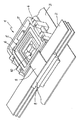
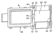
図1は、幾つかの平坦な導体ストリップ2を、基板3、例えば自動車の車体に固定するように意図された固定装置1を示す。この固定装置1は、台座4と、上下に配置され、該台座4の中央凹部7内の固定部分6によって固定された幾つかのホルダ5とを含む。各々のホルダ5は、台座4の外側に延びる保持部分8を有し、この保持部分に、閉鎖可能なフラップ9によって平坦な導体ストリップ2が取り付けられる。台座4は、該台座4の開口部内にボタン留めされたTボルト10を用いて、基板3に固定される。
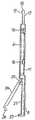
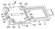
図2及び3から分かるように、ホルダ5は、矩形の保持部分8及び固定部分6に連接した、本質的に平坦な板の形態の基部部分11を有する。この固定部分6は、中央開口部12と、2つの短いフレーム脚部13、14と、2つの長いフレーム脚部15とを有するフレームの形態である。2つの長いフレーム脚部15は、外側が対称的な構成であり、ホルダ5を台座4上に支持するように働く2つの結節状の突出部16を支持する。固定部分6から離れた短いフレーム脚部13は、フレームの面に平行に延び、その自由端においてスナップフック18を支持し、該スナップフック18の止め面19が該フレーム脚部13に面した状態のばね舌部17をその外側に含む。
The present invention will now be described in more detail with respect to embodiments illustrated by way of example in the drawings.
FIG. 1 shows a
As can be seen from FIGS. 2 and 3, the holder 5 has a
固定部分6の短いフレーム脚部14は、フレーム脚部15の延長上にある2つの脚部20を含む保持部分8に接合されており、該保持部分は共通平面内にある支持面21を有する。この脚部20は、開口部22によって互いから分離され、フレーム脚部14に対向する両端部は、脚部23によって互いに連結される。開口部22の上方には、可撓性のヒンジ25によって脚部14に揺動可能に固定されたフラップ24がある。スライドを含まない簡単な成形金型でホルダを製造できるように、この開口部22が設けられる。フラップ24の自由端には、開口部22に向けて脚部23のセグメントに下から係合し、フラップ24を閉じ位置にロックするスナップノーズ26が設けられる。支持面21に沿って延びる延長部を有する脚部23は、支持面21上に配置された平坦な導体ストリップを案内し、支持するために、該支持面から突出し、横方向の支持をもたらす貫通リブ27を形成する。脚部20上には、リブ27から離れ且つ該リブ27と平行にリブ28が設けられ、これらのリブ28は、リブ27と同様にそれぞれの支持面21から突出し、該リブ27に面する該平坦な導体ストラップに対して横方向の支持をもたらす。
平坦な導体ストリップをホルダ5に固定するため、フラップ24が開けられた状態で、支持面21上に導体ストリップが配置される。次に、フラップ24が閉じられ、キャッチノーズ26を用いて脚部23に固定される。このように、平坦な導体ストリップは、ホルダ5の保持部分8によって完全に囲まれ、これにより、該ホルダ5に確実に連結される。
The
To secure the flat conductor strip to the holder 5, the conductor strip is placed on the
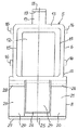
図4は、保持部分30が修正された形であり、平坦な導体ストリップに曲げを与えるのに適するようにされた点でホルダ5とは異なるホルダ29を示す。ホルダ29の固定部分は、ホルダ5のものと類似している。保持部分30は、台形の開口部32の上に配置された台形のフラップ31を有する。フラップ31の短い平行な側部が、可撓性のヒンジ33によって固定部分6のフレーム脚部14に連結される。フラップ31の長い平行な側部には、該フラップ31を図示される閉じ位置に保持するように、保持部分30の外側脚部35の凹部内にスナップ嵌めするスナップバー34が設けられる。フラップ31の側縁36は、脚部35の長手方向軸に対して45度の角度で傾斜されている。
保持部分30内に配置され、閉じられたフラップ31により固定された平坦な導体ストリップを、側縁36の一方の上で90°の角度に折り曲げることによって、曲がりを与えることができる。平坦な導体ストリップが両方の側縁36上で折り曲げられた場合には、該平坦な導体ストリップは、180度の角度の曲がりを与えられる。曲がりのない場合には、開口部32の両側に配置された保持部分30の脚部37は、平坦な導体ストリップを案内し、これを支持するように働く。曲がりのある場合には、それらの突出部のために、脚部37は、平坦な導体ストリップの折り曲げられた縁に対する横方向の保護をもたらす。
FIG. 4 shows a holder 29 which differs from the holder 5 in that the holding
A bend can be provided by folding a flat conductor strip, which is arranged in the holding
図5は、ホルダ38とは別に製造され、次に該ホルダ38に移動可能に連結されたフラップ39を有するホルダ38を示す。ここでの基部部分40は、保持部分において、フラップ39の下を通って延びる閉鎖された板41を含み、ホルダ5に隣接する補強された長い側部において、この板は、互いから離れて配置された2つの支持溝42を有する。支持溝42において、フラップ39の一端に配置された円筒形の支持ピン43が受けられる。支持ピン43は、その周囲の半分以上にわたって支持溝42に係合する。支持溝42のアパーチャは、該支持ピンの直径より小さいので、該支持ピンは、幾何学的に該支持溝42内に保持される。他方、支持溝42の開口部は、弾力のある材料の変形性を利用して支持ピン43を該支持溝42内にボタン留めするのを可能にするのに十分に広い。
FIG. 5 shows the
閉じ位置において、フラップ39は、支持溝42間の中央の基部部分40上に配置され、該フラップ39の上部の凹部45に係合するリブ44によって、支持ピン43により生じる旋回軸における緩みを防止するようにさらに固定される。フラップ39が完全に開いた場合には、凹部45の縁部はリブ44から遠く離れているので、該フラップ39の支持溝42内への挿入が、リブ44によって妨げられることはない。
既に説明された他のホルダにおけるように、フラップ39も同様に、その自由端におけるキャッチと協働するように基部部分40の弾性的に変形可能な脚部47により形成されたスナップ閉鎖46によって、閉じ位置に保持される。
In the closed position, the
As in the other holders already described, the
図6から図8に示されるホルダ48の構造の場合には、基部部分49と別に製造されるフラップ50が、完全に対称的な構成でできている。このことは、組立て前のフラップ50の位置の配向を簡単にし、該フラップ50の自動取付けを容易にする。図5のホルダにおけるように、フラップ50は、基部部分49内の支持溝42a、42b内にボタン留めすることができる支持ピン43a、43bを含む。その対称的な構造のために、フラップ50が4つの支持ピンを有するので、基部部分49には、同様に該支持ピンに関連した4つの支持溝が設けられる。ここでは、固定部分6に隣接する支持溝42a及び支持ピン43aは、フラップ50を揺動可能に取付けるために働き、一方、保持部分51の自由端に配置された支持溝42bは、支持ピン43bを、よってフラップ50を、閉じ位置にしっかりと保持するためにだけ働く。さらに、フラップ50は、保持部分51の自由端に配置され、該フラップ50の縁に沿って延びるレッジ53を把持するばねキャッチ52によって閉じ位置に固定される。レッジ53は、キャッチ52の両側の基部部分49内の凹部55に係合する2つの突出部54を有する。揺動支持として働くフラップ50の他側においては、図において見ることができない突出部54が、基部部分49の支持溝42の間を延びるセグメント56をつかみ、これにより、該フラップ50の揺動支持側が、該基部部分49から緩むのが防止される。
In the case of the structure of the
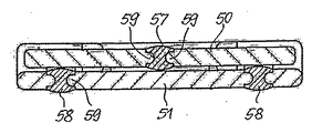
特に図7に見ることができるように、所定の圧力を用いて平坦な導体ストリップを保持部分51内にクランプし、該平坦な導体ストリップが長手方向に移動するのを防止するために、例えば、ゴム又はTPEのような柔らかい弾力のある材料でできた挿入体57、58を、フラップ50内及び該フラップ50によって覆われた基部部分49に配置する。この挿入体57、58は、フラップ50及び基部部分49の支持面の全幅にわたる所定の位置で、クランプされるべき平坦な導体ストリップの長手方向に対し横方向に延びる。挿入体57、58は、フラップ50のスロット及び/又は基部部分49のスロット内に配置され、わずかに凸状の面を有する該フラップ50又は基部部分49の両側において、それらから突出する。スロット内に配置された挿入体の長手方向側部において、挿入体56、57には溝が形成され、これら溝に係合するフラップ50及び基部部分49の突出部59によって、幾何学的に保持される。対称であるという理由により、フラップ50上には挿入体57が中央に配置される。基部部分49では、2つの挿入体58が、中心から同じ距離で配置される。平坦な導体ストリップの厚さによって、フラップ50を閉じるとき、挿入体57、58は、多かれ少なかれスロット内にしっかりと押し付けられ、よって、所定の力で平坦な導体ストリップに作用し、摩擦によって、該平坦な導体ストリップをホルダ内にロックする。
As can be seen in particular in FIG. 7, in order to clamp the flat conductor strip into the holding
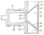
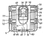
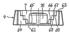
固定装置1の台座4が、図8から図11までに示される。この台座4は、本質的に矩形の角柱形状であり、長手方向の中心面Eに対して対称的に構成される。台座4は、その長い側部に補強リブ60、61が設けられる。
補強リブ60は底面62に垂直に配向され、補強リブ61が平行に配向される。台座4には、上部63及び前端部64で開いた凹部7がある。凹部7は底面65を有し、その上方に位置する2つの平面において、底面に平行な階段状面66、67が階段68、69により形成され、凹部7を上部63に向かって、面Eに平行な方向に向かって拡大する。補強リブ60の内側には、階段68、69の領域において台座4を底面62から上部63まで完全に貫通する溝70が設けられる。溝70は、平行な側壁71、72を有する。側壁72には、ブロック形状の凹部が横方向に並んで形成され、この凹部は、底面62の所まで延び、各々が階段の高さのおよそ半分に配置された端面75を有し、階段状面66、67から及びこれに平行な上部63から離れて延びる。端面75は、図11に見ることができる。端面74と各々がより深い位置にある隣接する階段状面66、67又は底面65との間には、切り欠き73が凹部7に向けて開いている。並んで配置された幾つかの切り欠き73の代わりに、代替的に、対応して配置された端面を有する単一の切り欠きを側壁72に設けてもよく、アパーチャ開口部を凹部7に設けてもよい。
The
The reinforcing
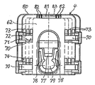
階段68、69から離れて凹部7の中央には、凹部7の底部において固定開口部76を部分的に囲む壁75がある。壁75は、開口部の上に配置されたラッチ77を支持する。ラッチ77に対向して、開口部76の縁部に案内ストラット78が設けられ、これを用いて台座4を基板3に固定するボルト10を受けるための固定開口部79を境界付ける。台座4がTボルト10上に位置させられたとき、ラッチ77により、ばね作用が生じ、該Tボルト10が固定開口部79内に係合されるとすぐに、ロック位置に再び嵌まる。ロック位置において、ラッチ77は、Tボルト10を固定開口部79内にロックする、図13を参照されたい。
図8から図11までに見られるように、台座4の後端部80において、幅が上から下に2段階で増加する開口部81がある。各々の階段セグメントは、ホルダの舌部を受けるように意図されている。階段においては、舌部の端部に配置されたスナップフックに係合できる凹部82がある。対応する凹部83が、開口部81の上縁部に設けられる。
Apart from the
As can be seen from FIGS. 8 to 11, at the
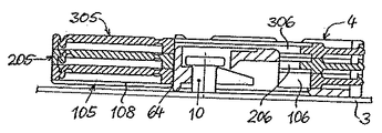
図12から図15まで、幾つかのホルダ105、205及び305の台座4への連結が示される。ホルダ105、205及び305は、図2及び図3に示されるホルダ5とほぼ同じ構造でできている。しかしながら、それらは、互いに対向する階段68、69の距離に適合されたそれらの固定部分の幅、又は凹部7の上部開口部の幅について異なっている。ホルダ105の固定部分106は、最小の幅を有し、階段68の間に位置させるためのものである。組立て中、固定部分106を有するホルダ105は、横方向の突出部116が溝70に係合する状態で、上方から台座4の凹部7に置かれる。この作業において、固定部分106は、舌部117の端部が凹部7の内部に配置された該凹部7内の位置にある。固定部分106が底面65に載るとすぐに、ホルダ105が台座4の後端部80に向けて移動される。その後、突出部116は切り欠き73に入り、舌部117のスナップフック118は開口部81の底部セグメントに入り、その結果、該舌部117は、ばね作用により下方に折れる。図12に示されるように、保持部分108が台座4の前端部64に当接するとき、最終位置に到達する。この位置において、スナップフック118は、開口部81の凹部82に係合し、これにより、ホルダ105が台座4にしっかりと保持される。この位置における突出部116は、それらの端面74の下の切り欠き73内に配置され、これにより、凹部7からの持ち上げに逆らって、該ホルダ5が幾何学的に固定される。
12 to 15, the connection of
スナップフック118の舌部117に上から圧力をかけて該舌部177を凹部82から取り出し、同時に保持部分108によってホルダ5を前方に引くことによって、該ホルダ105を台座4からはずすことができる。他のホルダがない場合には、もう一度突出部116が溝70内に配置されるとすぐに、ホルダ105を台座4から上方に取り出すことができる。
ホルダ205及び305の取付けは、先に説明された方法で同様に行うことができ、固定部分206を有するホルダ205は、階段69の間に配置され、ホルダ305の固定部分306は、凹部7の開口部内に配置される。固定部分206及び306の幅は、対応して大きくなり、舌部217、317の幅は、対応して小さくなる。したがって、幾つかの固定部分の異なる寸法から、当業者であれば、どのようなシーケンスでホルダを次々に取り付けるべきかを容易に理解することができる。
The
The mounting of the
図15は、2つのホルダ105及び205だけが台座4内に挿入された適用例を示す。ホルダ305の受け部は空である。したがって、ホルダ305が配置された階段状面67、溝70、及び突出部316を受けるための切り欠き73が、容易に認識できる。
FIG. 15 shows an application example in which only two
1:固定装置
2:平坦な導体ストリップ
3:基板
4:台座
5、29、38、48、105、205、305:ホルダ
6、106、206、306:固定部分
7、12、42:凹部
8、51:保持部分
9、24、39、50:フラップ
10:固定ピン
11、40、49:基部部分
16、54:突出部
21:支持面
43:支持ピン
70:溝
73:切り欠き
1: fixing device 2: flat conductor strip 3: substrate 4:
Claims (22)
Applications Claiming Priority (1)
| Application Number | Priority Date | Filing Date | Title |
|---|---|---|---|
| DE10312015A DE10312015B4 (en) | 2003-03-18 | 2003-03-18 | Fastening device for elongate, flat objects, in particular ribbon cables |
Publications (1)
| Publication Number | Publication Date |
|---|---|
| JP2004282994A true JP2004282994A (en) | 2004-10-07 |
Family
ID=32797958
Family Applications (1)
| Application Number | Title | Priority Date | Filing Date |
|---|---|---|---|
| JP2004069070A Ceased JP2004282994A (en) | 2003-03-18 | 2004-03-11 | Fixing device for long flat object, particularly for flat conductor strip |
Country Status (5)
| Country | Link |
|---|---|
| US (1) | US7048592B2 (en) |
| EP (1) | EP1460322B1 (en) |
| JP (1) | JP2004282994A (en) |
| DE (2) | DE10312015B4 (en) |
| ES (1) | ES2342164T3 (en) |
Cited By (1)
| Publication number | Priority date | Publication date | Assignee | Title |
|---|---|---|---|---|
| JP2008186706A (en) * | 2007-01-30 | 2008-08-14 | Fujikura Ltd | Connector for flat harness |
Families Citing this family (2)
| Publication number | Priority date | Publication date | Assignee | Title |
|---|---|---|---|---|
| DE102005020011A1 (en) | 2005-04-27 | 2006-11-23 | Newfrey Llc, Newark | Clip and fastening system with a clip |
| US7976333B2 (en) | 2009-09-29 | 2011-07-12 | Flex-Cable | Laminar electrical connector |
Family Cites Families (11)
| Publication number | Priority date | Publication date | Assignee | Title |
|---|---|---|---|---|
| US3715705A (en) * | 1971-03-29 | 1973-02-06 | Thomas & Betts Corp | Multicompartment connector |
| CH549988A (en) * | 1972-06-16 | 1974-06-14 | Bratschi Silent Gliss | FASTENING DEVICE. |
| US4356799A (en) * | 1978-04-19 | 1982-11-02 | Eaton Corporation | Spring retainer-valve selector |
| US4913656A (en) * | 1989-04-07 | 1990-04-03 | Rogers Corporation | Electrical connector |
| US5151560A (en) * | 1990-12-10 | 1992-09-29 | Amp Incorporated | Grounding connector |
| US5817983A (en) * | 1997-02-25 | 1998-10-06 | Raychem Corporation | arrangement for holding elongate substrates |
| JPH11122759A (en) | 1997-10-17 | 1999-04-30 | Fujikura Ltd | Clip for flat cable |
| US6771516B1 (en) * | 1999-12-27 | 2004-08-03 | Micron Technology, Inc. | Method and apparatus for fastening circuit boards to computer chassis |
| JP2002010452A (en) * | 2000-06-21 | 2002-01-11 | Yazaki Corp | Support construction for clamp to flat cable |
| DE10045765C1 (en) * | 2000-09-15 | 2002-05-02 | Leoni Bordnetz Sys Gmbh & Co | Deflection device for a ribbon cable |
| DE10051120A1 (en) * | 2000-10-14 | 2002-04-25 | Raymond A & Cie | Device for retaining and/or fixing of flat objects, especially ribbon cable for motor vehicle bodywork parts, includes base plate from which extend two elastically splayed extensions, the ends of which are joined via a three-part web |
-
2003
- 2003-03-18 DE DE10312015A patent/DE10312015B4/en not_active Expired - Fee Related
-
2004
- 2004-03-11 JP JP2004069070A patent/JP2004282994A/en not_active Ceased
- 2004-03-12 EP EP04005931A patent/EP1460322B1/en not_active Expired - Fee Related
- 2004-03-12 DE DE502004011115T patent/DE502004011115D1/en not_active Expired - Lifetime
- 2004-03-12 ES ES04005931T patent/ES2342164T3/en not_active Expired - Lifetime
- 2004-03-17 US US10/801,677 patent/US7048592B2/en not_active Expired - Fee Related
Cited By (1)
| Publication number | Priority date | Publication date | Assignee | Title |
|---|---|---|---|---|
| JP2008186706A (en) * | 2007-01-30 | 2008-08-14 | Fujikura Ltd | Connector for flat harness |
Also Published As
| Publication number | Publication date |
|---|---|
| DE502004011115D1 (en) | 2010-06-17 |
| DE10312015B4 (en) | 2006-10-19 |
| US7048592B2 (en) | 2006-05-23 |
| EP1460322B1 (en) | 2010-05-05 |
| EP1460322A1 (en) | 2004-09-22 |
| US20040235362A1 (en) | 2004-11-25 |
| ES2342164T3 (en) | 2010-07-02 |
| DE10312015A1 (en) | 2004-10-07 |
Similar Documents
| Publication | Publication Date | Title |
|---|---|---|
| US6943297B2 (en) | Low voltage device used as an electrical outlet base plate | |
| JPH079343Y2 (en) | Connector with terminal locking device | |
| US4922056A (en) | Surface mounted box | |
| US7207529B2 (en) | Clamp for holding of flat objects | |
| JP2004122809A (en) | Floor carpet and fastener of wire harness | |
| KR20020030260A (en) | Child car seat and belt locking apparatus used therefor | |
| HU221471B (en) | Anchoring clip for duct, especially for electric equipment | |
| EP2778442B1 (en) | Fastening method and apparatus | |
| US6494412B2 (en) | Device for holding and/or attaching flat objects | |
| US11933436B2 (en) | Clamp assembly | |
| JP2835675B2 (en) | Locking device for electronic unit | |
| JP2004282994A (en) | Fixing device for long flat object, particularly for flat conductor strip | |
| JP3821897B2 (en) | Electrical equipment fixing device | |
| US20020106239A1 (en) | Spring-loaded wedge dead end connector having elements for coupling together and preventing removal of conductor-gripping jaws | |
| TWI743124B (en) | Housing system for electrical connectors and electrical connector having the same | |
| AU2002251878A1 (en) | Spring-loaded wedge dead end connector | |
| US5590909A (en) | File cover restraining device | |
| US7472460B2 (en) | Clamping apparatus | |
| JP3039368B2 (en) | Sheet material holder and partition device using the same | |
| DK2236886T3 (en) | installation section | |
| JPH06227434A (en) | Holder for trunk lid torsion bar spring | |
| KR200141592Y1 (en) | Locking device for a disconnecting console tray in a vehicle | |
| KR100186701B1 (en) | Clip | |
| GB2203002A (en) | Cable clamp | |
| JPH10174256A (en) | Locking tool of electric wire |
Legal Events
| Date | Code | Title | Description |
|---|---|---|---|
| A621 | Written request for application examination |
Free format text: JAPANESE INTERMEDIATE CODE: A621 Effective date: 20070124 |
|
| A131 | Notification of reasons for refusal |
Free format text: JAPANESE INTERMEDIATE CODE: A131 Effective date: 20080225 |
|
| A601 | Written request for extension of time |
Free format text: JAPANESE INTERMEDIATE CODE: A601 Effective date: 20080523 |
|
| A602 | Written permission of extension of time |
Free format text: JAPANESE INTERMEDIATE CODE: A602 Effective date: 20080528 |
|
| A521 | Written amendment |
Free format text: JAPANESE INTERMEDIATE CODE: A523 Effective date: 20080822 |
|
| A131 | Notification of reasons for refusal |
Free format text: JAPANESE INTERMEDIATE CODE: A131 Effective date: 20081006 |
|
| A521 | Written amendment |
Free format text: JAPANESE INTERMEDIATE CODE: A523 Effective date: 20081225 |
|
| A01 | Written decision to grant a patent or to grant a registration (utility model) |
Free format text: JAPANESE INTERMEDIATE CODE: A01 Effective date: 20090126 |
|
| A045 | Written measure of dismissal of application [lapsed due to lack of payment] |
Free format text: JAPANESE INTERMEDIATE CODE: A045 Effective date: 20090525 |