EP1843042A1 - Schwenkmotor - Google Patents
Schwenkmotor Download PDFInfo
- Publication number
- EP1843042A1 EP1843042A1 EP07006110A EP07006110A EP1843042A1 EP 1843042 A1 EP1843042 A1 EP 1843042A1 EP 07006110 A EP07006110 A EP 07006110A EP 07006110 A EP07006110 A EP 07006110A EP 1843042 A1 EP1843042 A1 EP 1843042A1
- Authority
- EP
- European Patent Office
- Prior art keywords
- cylinder
- motor shaft
- component
- ribs
- adapter
- Prior art date
- Legal status (The legal status is an assumption and is not a legal conclusion. Google has not performed a legal analysis and makes no representation as to the accuracy of the status listed.)
- Withdrawn
Links
- 230000000712 assembly Effects 0.000 description 1
- 238000000429 assembly Methods 0.000 description 1
- 238000010276 construction Methods 0.000 description 1
- 230000007423 decrease Effects 0.000 description 1
- 230000000694 effects Effects 0.000 description 1
- 238000001125 extrusion Methods 0.000 description 1
- 239000012530 fluid Substances 0.000 description 1
- 238000004519 manufacturing process Methods 0.000 description 1
- 238000000034 method Methods 0.000 description 1
- 239000003381 stabilizer Substances 0.000 description 1
Images

Classifications
-
- F—MECHANICAL ENGINEERING; LIGHTING; HEATING; WEAPONS; BLASTING
- F04—POSITIVE - DISPLACEMENT MACHINES FOR LIQUIDS; PUMPS FOR LIQUIDS OR ELASTIC FLUIDS
- F04C—ROTARY-PISTON, OR OSCILLATING-PISTON, POSITIVE-DISPLACEMENT MACHINES FOR LIQUIDS; ROTARY-PISTON, OR OSCILLATING-PISTON, POSITIVE-DISPLACEMENT PUMPS
- F04C9/00—Oscillating-piston machines or pumps
- F04C9/002—Oscillating-piston machines or pumps the piston oscillating around a fixed axis
-
- F—MECHANICAL ENGINEERING; LIGHTING; HEATING; WEAPONS; BLASTING
- F15—FLUID-PRESSURE ACTUATORS; HYDRAULICS OR PNEUMATICS IN GENERAL
- F15B—SYSTEMS ACTING BY MEANS OF FLUIDS IN GENERAL; FLUID-PRESSURE ACTUATORS, e.g. SERVOMOTORS; DETAILS OF FLUID-PRESSURE SYSTEMS, NOT OTHERWISE PROVIDED FOR
- F15B15/00—Fluid-actuated devices for displacing a member from one position to another; Gearing associated therewith
- F15B15/08—Characterised by the construction of the motor unit
- F15B15/12—Characterised by the construction of the motor unit of the oscillating-vane or curved-cylinder type
-
- F—MECHANICAL ENGINEERING; LIGHTING; HEATING; WEAPONS; BLASTING
- F01—MACHINES OR ENGINES IN GENERAL; ENGINE PLANTS IN GENERAL; STEAM ENGINES
- F01C—ROTARY-PISTON OR OSCILLATING-PISTON MACHINES OR ENGINES
- F01C21/00—Component parts, details or accessories not provided for in groups F01C1/00 - F01C20/00
- F01C21/08—Rotary pistons
-
- F—MECHANICAL ENGINEERING; LIGHTING; HEATING; WEAPONS; BLASTING
- F01—MACHINES OR ENGINES IN GENERAL; ENGINE PLANTS IN GENERAL; STEAM ENGINES
- F01C—ROTARY-PISTON OR OSCILLATING-PISTON MACHINES OR ENGINES
- F01C21/00—Component parts, details or accessories not provided for in groups F01C1/00 - F01C20/00
- F01C21/10—Outer members for co-operation with rotary pistons; Casings
-
- F—MECHANICAL ENGINEERING; LIGHTING; HEATING; WEAPONS; BLASTING
- F04—POSITIVE - DISPLACEMENT MACHINES FOR LIQUIDS; PUMPS FOR LIQUIDS OR ELASTIC FLUIDS
- F04C—ROTARY-PISTON, OR OSCILLATING-PISTON, POSITIVE-DISPLACEMENT MACHINES FOR LIQUIDS; ROTARY-PISTON, OR OSCILLATING-PISTON, POSITIVE-DISPLACEMENT PUMPS
- F04C2230/00—Manufacture
- F04C2230/20—Manufacture essentially without removing material
- F04C2230/23—Manufacture essentially without removing material by permanently joining parts together
- F04C2230/231—Manufacture essentially without removing material by permanently joining parts together by welding
-
- F—MECHANICAL ENGINEERING; LIGHTING; HEATING; WEAPONS; BLASTING
- F04—POSITIVE - DISPLACEMENT MACHINES FOR LIQUIDS; PUMPS FOR LIQUIDS OR ELASTIC FLUIDS
- F04C—ROTARY-PISTON, OR OSCILLATING-PISTON, POSITIVE-DISPLACEMENT MACHINES FOR LIQUIDS; ROTARY-PISTON, OR OSCILLATING-PISTON, POSITIVE-DISPLACEMENT PUMPS
- F04C2240/00—Components
- F04C2240/70—Use of multiplicity of similar components; Modular construction
Definitions
- the invention relates to a fluid-operated pivoting motor according to the preamble of claim 1.
- a fluid operated swing motor having a winged motor shaft and a cylinder with axially extending ribs.
- the wings and the ribs define together with end caps work spaces that are supplied arbitrarily with pressure medium and thereby generate a relative movement between the motor shaft and cylinder.
- the torsional moment of the slewing motor include the wing or rib length and the radial extent of the wings or ribs and the average radius of the ribs or wings.
- An engine-side increase in the torsional moment is possible if one of the enumerated parameters is increased. Additionally you can check the number of working chambers by an inevitable increasing number of wings and ribs, but with the disadvantage that the pivoting angle decreases.
- An increase in the pressure of the pressure medium degrades the extrusion behavior and the durability of the standard lines and seals used in the ribs and wings.
- the object of the present invention is to provide a swing motor concept that allows for a very large bandwidth with regard to the executable torsional moment.
- At least one of the main assemblies cylinder or motor shaft has a base member and at least one adapter component for extending the working spaces.
- the adapter components are used, wherein the end-side cover can be used independently of the length of the swivel motor so that standardized components can be used.
- a cylinder made of a base member and adapter components can be much easier to produce, in particular to produce the ribs and the inner wall by a clearing process.
- the smallest angular errors of the clearances have an immediate effect.
- the tool costs increase extremely.
- the basic component of the cylinder is designed at the end with a contact surface to a cover, wherein the adapter component of the cylinder for the basic component of the cylinder has a contour similar to the contact surface with the cover.
- the contact surface of the base component to the cover and the adapter component is formed by a paragraph.
- the basic component of the motor shaft is designed with a bearing seat surface for a pivot bearing in both lids, wherein the adapter component of the motor shaft for the base member of the motor shaft has a receptacle with a diameter as for the bearing seat surface of the second pivot bearing in the second cover. Also in the case of the motor shaft, similar to the cylinder, the effective length of the motor shaft can be increased by simply pushing on the adapter pieces.
- a plurality of axially arranged in series disc seals are executed in the wings and ribs. This sectional arrangement of the disc seals facilitates the assembly enormous.
- the effective length of an adapter component of the cylinder and / or the motor shaft is equal to the effective length of the basic component of the cylinder and / or the motor shaft designed so that you have to stockpile only a dimension of disc seals.
- the welded connections between the covers and the base component and the at least one adapter component of the cylinder are designed radially on a lateral surface of the cylinder.
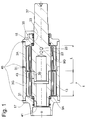
- FIG. 1 The synopsis of Figures 1 and 2 describes a pivot motor 1, which has a cylinder 3, on the inner wall 5 axially extending ribs 7 are executed.
- a motor shaft 9 is pivotally mounted, which has parallel to the ribs extending wings 11.
- a disc seal 13 is arranged, which have identical dimensions.
- the swivel motor is closed by a first cover 15 and a second cover 17, so that alternating work spaces 19; 21 are present, each via transverse openings 23; 25 are connected in pairs in the motor shaft.
- the first cover 15 is in each case a pressure port 27; 29 ( Figure 2) for a pair of working rooms.
- the cylinder 3 as a main assembly of the swing motor includes a base member 3G and at least one adapter member 3A.
- the basic component 3G is used regardless of the number of adapter components 3A and determined with the distance between the inside of the lid 17 and the end of the rib a effective length L.
- a shoulder 31 is formed so that axially extending contact surfaces on the one hand to cover 17 and the adapter component 3A present.
- the adapter component 3A has the same outer diameter as the cover 17 in the area of the contact surface.
- the adapter component 3A has the same contours as the basic component 3G to the cover 17, so that the adapter component 3A into the basic component 3G insert the cylinder and can provide an arbitrarily long arrangement of adapter components 3a.
- the main assembly motor shaft comprises a base member 9G with the two transverse openings 23; 25, a bearing seat surface 33 for a first pivot bearing 35 and a mounting boss 37, z. B. for a stabilizer, not shown.
- the basic component 9G of the motor shaft On a shoulder in the direction of the second cover 17, the basic component 9G of the motor shaft has a bearing seat surface 39 for a second pivot bearing 41. If, as in the illustrated embodiment, the motor shaft is extended by an adapter component 9A, the bearing seat surface 39 engages in a receptacle 43, the inner diameter of which is adapted to the diameter of the bearing seat surface 39 and constitutes a torsion-proof connection.
- the effective length L of the adapter components 3A, 9A of the cylinder 3 and the motor shaft 9 are equal to the effective length L of the basic components 3G; 9G, so that the disc seals 13 can be installed in axial row arrangement.
- the base member 3G, the adapter member 3A of the cylinder and the covers 15; 17 are each connected to each other by radially extending welds 45 on the lateral surface.
- the same principle is used for the connection between the parts of the motor shaft.
Landscapes
- Engineering & Computer Science (AREA)
- Mechanical Engineering (AREA)
- General Engineering & Computer Science (AREA)
- Physics & Mathematics (AREA)
- Fluid Mechanics (AREA)
- Connection Of Motors, Electrical Generators, Mechanical Devices, And The Like (AREA)
Abstract
Description
- Die Erfindung betrifft einen druckmittelbetriebenen Schwenkmotor nach dem Oberbegriff von Patentanspruch 1.
- Aus der
DE 43 37 815 C1 ist ein druckmittelbetriebener Schwenkmotor bekannt, der eine mit Flügeln bestückte Motorwelle und einen Zylinder mit axial verlaufenden Rippen aufweist. Die Flügel und die Rippen begrenzen zusammen mit endseitigen Deckeln Arbeitsräume, die willkürlich mit Druckmittel versorgt werden und dadurch eine Relativbewegung zwischen Motorwelle und Zylinder erzeugen. - In die Berechnung des Torsionsmoments des Schwenkmotors gehen u. a. die Flügel- oder Rippenlänge und die radiale Erstreckung der Flügel oder Rippen sowie der mittlere Radius der Rippen oder Flügel ein. Eine motorseitige Steigerung des Torsionsmoments ist möglich, wenn einer der aufgezählten Parameter erhöht wird. Zusätzlich kann man die Anzahl der Arbeitskammern durch eine zwangsläufige zunehmende Zahl von Flügel und Rippen steigern, jedoch mit dem Nachteil, dass der Schwenkwinkel abnimmt. Eine Druckerhöhung des Druckmediums verschlechtert das Extrusionsverhalten und die Haltbarkeit der standardmäßig verwendeten Leitungen und Dichtungen in den Rippen und Flügeln.
- Eine Lösung des beschriebenen Widerspruchs könnte in der Konstruktion des Schwenkmotors nach der
DE 10 2004 002 550 A1 gesehen werden. Ein Problem besteht jedoch darin, dass der benötigte radiale Bauraum beträchtlich ist und der Fertigungsaufwand für den inneren Zylinder, der am Innendurchmesser die Rippen und am Außendurchmesser Flügel wie eine Motorwelle aufweist, sehr beträchtlich ist. Es handelt sich im Vergleich zum Schwenkmotor nach derDE 43 37 815 C1 um ein völlig anderes Bauprinzip, so dass Bauteile zwischen diesen beiden Schwenkmotortypen nicht kompatibel sind. - Die Aufgabe der vorliegenden Erfindung besteht darin, ein Schwenkmotorkonzept zu bieten, dass hinsichtlich des ausführbaren Torsionsmoments eine sehr große Bandbreite ermöglicht.
- Erfindungsgemäß wird die Aufgabe dadurch gelöst, dass mindestens eine der Hauptbaugruppen Zylinder oder Motorwelle ein Grundbauteil und mindestens ein Adapterbauteil zur Verlängerung der Arbeitsräume aufweist.
- Je nach gefordertem Torsionsmoment werden die Adapterbauteile verwendet, wobei die endseitigen Deckel unabhängig von der Länge des Schwenkmotors einsetzbar sind, so dass standardisierte Bauteile zur Anwendung kommen können. Im Vergleich zu einem einteiligen Zylinder mit einer vergrößerten Länge lässt sich ein Zylinder aus einem Grundbauteil und Adapterbauteilen sehr viel leichter herstellen, insbesondere die Rippen und die Innenwandung durch ein Räumverfahren erzeugen. Bei einem extrem langen Zylinder wirken sich kleinste Winkelfehler der Räumahle unmittelbar aus. Des Weiteren steigen die Werkzeugkosten extrem an.
- Des Weiteren ist vorgesehen, dass das Grundbauteil des Zylinders endseitig mit einer Kontaktfläche zu einem Deckel ausgeführt ist, wobei das Adapterbauteil des Zylinders für das Grundbauteil des Zylinders einen Konturenverlauf gleichartig wie die Kontaktfläche zum Deckel aufweist. Diese besondere Ausgestaltung ermöglicht das einfache Aufstecken auch mehrerer Adapterbauteile.
- Gemäß einem vorteilhaften Unteranspruch wird die Kontaktfläche des Grundbauteils zum Deckel und zum Adapterbauteil von einem Absatz gebildet.
- Das Grundbauteil der Motorwelle ist mit einer Lagersitzfläche für ein Schwenklager in beiden Deckeln ausgeführt, wobei das Adapterbauteil der Motorwelle für das Grundbauteil der Motorwelle eine Aufnahme mit einem Durchmesser wie für die Lagersitzfläche des zweiten Schwenklagers in dem zweiten Deckel aufweist. Auch bei der Motorwelle kann ähnlich wie beim Zylinder durch einfaches Aufschieben der Adapterstücke die Wirklänge der Motorwelle vergrößert werden.
- Vorteilhafterweise sind in den Flügeln und Rippen mehrere axial in Reihe angeordnete Scheibendichtungen ausgeführt. Diese abschnittsweise Anordnung der Scheibendichtungen erleichtert die Montage ungemein.
- Um die Teilevielzahl zu begrenzen, ist die Wirklänge eines Adapterbauteils des Zylinders und/oder der Motorwelle gleich der Wirklänge des Grundbauteils des Zylinders und/oder der Motorwelle ausgeführt, so dass man nur eine Abmessung von Scheibendichtungen bevorraten muss.
- Für eine einfache Montageeinrichtung sind die Schweißverbindungen zwischen den Deckeln und dem Grundbauteil und dem mindestens einen Adapterbauteil des Zylinders radial an einer Mantelfläche des Zylinders ausgeführt.
- Anhand der folgenden Figurenbeschreibung soll die Erfindung näher erläutert werden.
- Es zeigt:
- Fig. 1
- Schwenkmotor im Längsschnitt
- Fig. 2
- Schwenkmotor im Querschnitt
- Die Zusammenschau der Figuren 1 und 2 beschreibt einen Schwenkmotor 1, der einen Zylinder 3 aufweist, an dessen Innenwandung 5 axial verlaufende Rippen 7 ausgeführt sind. Im Zylinder 3 ist eine Motorwelle 9 schwenkbar gelagert, die parallel zu den Rippen verlaufende Flügel 11 aufweist. In jedem Flügel 11 und jeder Rippe 7 ist eine Scheibendichtung 13 angeordnet, die identische Abmessungen aufweisen. Endseitig wird der Schwenkmotor von einem ersten Deckel 15 und einem zweiten Deckel 17 verschlossen, so dass abwechselnd Arbeitsräume 19; 21 vorliegen, die jeweils über Queröffnungen 23; 25 in der Motorwelle paarweise miteinander verbunden sind. Im ersten Deckel 15 ist jeweils ein Druckanschluss 27; 29 (Fig. 2) für ein Arbeitsraumpaar angeordnet.
- Zur Anpassung des Schwenkmotors an ein größeres Anwendungsspektrum ist der Schwenkmotor modular aufgebaut. Der Zylinder 3 als eine Hauptbaugruppe des Schwenkmotors umfasst ein Grundbauteil 3G und mindestens ein Adapterbauteil 3A. Das Grundbauteil 3G kommt unabhängig von der Anzahl der Adapterbauteile 3A zur Anwendung und bestimmt mit dem Abstand zwischen der Innenseite des Deckels 17 und dem Ende der Rippe eine Wirklänge L. An beiden Enden des Grundbauteils 3G ist ein Absatz 31 angeformt, so dass axial verlaufende Kontaktflächen einerseits zum Deckel 17 und zum Adapterbauteil 3A vorliegen. Das Adapterbauteil 3A verfügt im Bereich der Kontaktfläche über denselben Außendurchmesser wie der Deckel 17. Am anderen Ende in Richtung des Deckels 15 weist das Adapterbauteil 3A den gleichartigen Konturenverlauf wie das Grundbauteil 3G zum Deckel 17 auf, so dass man das Adapterbauteil 3A in das Grundbauteil 3G des Zylinders einschieben und eine beliebig lange Anordnung von Adapterbauteilen 3a vorsehen kann.
- Auch die Hauptbaugruppe Motorwelle umfasst ein Grundbauteil 9G mit den beiden Queröffnungen 23; 25, eine Lagersitzfläche 33 für ein erstes Schwenklager 35 und einem Befestigungsansatz 37, z. B. für einen nicht dargestellten Stabilisator. Auf einem Absatz in Richtung des zweiten Deckels 17 verfügt das Grundbauteil 9G der Motorwelle über eine Lagersitzfläche 39 für ein zweites Schwenklager 41. Wenn, wie in der dargestellten Ausführung auch die Motorwelle um ein Adapterbauteil 9A verlängert ist, greift die Lagersitzfläche 39 in eine Aufnahme 43, deren Innendurchmesser dem Durchmesser der Lagersitzfläche 39 angepasst ist und eine verdrehsichere Verbindung darstellt.
- Die Wirklänge L der Adapterbauteile 3A, 9A des Zylinders 3 und der Motorwelle 9 gleichen der Wirklänge L der Grundbauteile 3G; 9G, so dass die Scheibendichtungen 13 in axialer Reihenanordnung verbaut werden können.
- Das Grundbauteil 3G, das Adapterbauteil 3A des Zylinders und die Deckel 15; 17 sind jeweils durch radial verlaufende Schweißverbindungen 45 an der Mantelfläche miteinander verbunden. Für die Verbindung zwischen den Teilen der Motorwelle wird das gleiche Prinzip verwendet.
Claims (7)
- Schwenkmotor, umfassend einen Zylinder mit axial verlaufende Rippen an dessen Innenwandung, eine Motorwelle mit außenseitigen Flügeln, die parallel zu den Rippen ausgeführt sind, sowie endseitig am Zylinder fixierte Deckel, die zusammen mit den Rippen des Zylinders und den Flügeln der Motorwelle Arbeitsräume begrenzen, die gegeneinander durch Scheibendichtungen abgedichtet sind,
dadurch gekennzeichnet,
dass mindestens eine der Hauptbaugruppen Zylinder (3) oder Motorwelle (9) ein Grundbauteil (3G; 9G) und mindestens ein Adapterbauteil (3A; 9A) zur Verlängerung der Arbeitsräume (19; 21) aufweist. - Schwenkmotor nach Anspruch 1,
dadurch gekennzeichnet,
dass das Grundbauteil (3G) des Zylinders (3) endseitig mit einer Kontaktfläche zu einem Deckel (15, 17) ausgeführt ist, wobei das Adapterbauteil (3A) des Zylinders (3) für das Grundbauteil (3G) des Zylinders (3) einen Konturenverlauf gleichartig wie die Kontaktfläche zum Deckel (15; 17) aufweist. - Schwenkmotor nach Anspruch 2,
dadurch gekennzeichnet,
dass die Kontaktfläche des Grundbauteils (3G) zum Deckel und zum Adapterbauteil (3A) von einem Absatz (31) gebildet wird. - Schwenkmotor nach Anspruch 1,
dadurch gekennzeichnet,
dass das Grundbauteil (9G) der Motorwelle (9) mit einer Lagersitzfläche (33; 39) für ein Schwenklager (35; 41) in beiden Deckeln (15; 17) ausgeführt ist, wobei das Adapterbauteil (9A) der Motorwelle (9) für das Grundbauteil (9G) der Motorwelle (9) eine Aufnahme (43) mit einem Durchmesser wie die Lagersitzfläche (39) für das zweite Schwenklager (41) in dem zweiten Deckel (17) aufweist. - Schwenkmotor nach Anspruch 1,
dadurch gekennzeichnet,
dass in den Flügeln (11) und Rippen (9) mehrere axial in Reihe angeordnete Scheibendichtungen (13) ausgeführt sind. - Schwenkmotor nach Anspruch 1,
dadurch gekennzeichnet,
dass die Wirklänge (L) eines Adapterbauteils (3A; 9A) des Zylinders (3) und/oder der Motorwelle (9) gleich der Wirklänge (L) des Grundbauteils (3G; 9G) des Zylinders (3) und/oder der Motorwelle (9) ausgeführt ist. - Schwenkmotor nach Anspruch 1,
dadurch gekennzeichnet,
dass Schweißverbindungen (45) zwischen den Deckeln (15; 17) und dem Grundbauteil (3G) und dem mindestens einen Adapterbauteil (3A) des Zylinders (3) radial an einer Mantelfläche des Zylinders (3) ausgeführt sind.
Applications Claiming Priority (1)
| Application Number | Priority Date | Filing Date | Title |
|---|---|---|---|
| DE200610016469 DE102006016469A1 (de) | 2006-04-07 | 2006-04-07 | Schwenkmotor |
Publications (1)
| Publication Number | Publication Date |
|---|---|
| EP1843042A1 true EP1843042A1 (de) | 2007-10-10 |
Family
ID=38229325
Family Applications (1)
| Application Number | Title | Priority Date | Filing Date |
|---|---|---|---|
| EP07006110A Withdrawn EP1843042A1 (de) | 2006-04-07 | 2007-03-24 | Schwenkmotor |
Country Status (2)
| Country | Link |
|---|---|
| EP (1) | EP1843042A1 (de) |
| DE (1) | DE102006016469A1 (de) |
Cited By (3)
| Publication number | Priority date | Publication date | Assignee | Title |
|---|---|---|---|---|
| EP3369929A1 (de) * | 2017-03-03 | 2018-09-05 | PistonPower ApS | Druckverstärker |
| US20220034226A1 (en) * | 2018-09-24 | 2022-02-03 | Rapson Gmbh | Piston machine, modular construction system for a piston machine, and method for producing a piston machine |
| CN116464601A (zh) * | 2023-03-10 | 2023-07-21 | 哈尔滨工业大学 | 一种双叶片式摆动液压马达 |
Families Citing this family (1)
| Publication number | Priority date | Publication date | Assignee | Title |
|---|---|---|---|---|
| DE102008030361A1 (de) | 2008-06-26 | 2009-12-31 | Kinshofer Gmbh | Wankstabilisatorsystem sowie Torsionsmotor zur Verstellung eines aktiven Wankstabilisators |
Citations (6)
| Publication number | Priority date | Publication date | Assignee | Title |
|---|---|---|---|---|
| GB2156001A (en) * | 1984-03-09 | 1985-10-02 | Festo Kg | Piston and cylinder actuators |
| FR2588322A1 (fr) * | 1985-10-03 | 1987-04-10 | Bitar Joseph | Machine hydraulique de structure modulaire |
| DE3730045A1 (de) * | 1987-09-08 | 1989-03-16 | Blohm Voss Ag | Mit druckmittel betriebener schwenkfluegelmotor |
| DE3902730A1 (de) * | 1989-01-31 | 1990-08-02 | Reinhold Dr Schilp | Digitalmotor |
| EP0394720A1 (de) * | 1989-04-28 | 1990-10-31 | Balzers-Pfeiffer GmbH | Pumpe zur Förderung von Gasen und zur Erzeugung eines Differenzdruckes |
| DE102004011852A1 (de) * | 2004-03-09 | 2005-09-01 | Zf Friedrichshafen Ag | Aggregat, insbesondere Schwenkmotor |
Family Cites Families (2)
| Publication number | Priority date | Publication date | Assignee | Title |
|---|---|---|---|---|
| DE4337815C1 (de) * | 1993-11-05 | 1995-02-16 | Fichtel & Sachs Ag | Schwenkmotor |
| AU2002246270A1 (en) * | 2002-04-15 | 2003-11-17 | Zoran Pavlovic | Oscillating-rotor engine |
-
2006
- 2006-04-07 DE DE200610016469 patent/DE102006016469A1/de not_active Withdrawn
-
2007
- 2007-03-24 EP EP07006110A patent/EP1843042A1/de not_active Withdrawn
Patent Citations (6)
| Publication number | Priority date | Publication date | Assignee | Title |
|---|---|---|---|---|
| GB2156001A (en) * | 1984-03-09 | 1985-10-02 | Festo Kg | Piston and cylinder actuators |
| FR2588322A1 (fr) * | 1985-10-03 | 1987-04-10 | Bitar Joseph | Machine hydraulique de structure modulaire |
| DE3730045A1 (de) * | 1987-09-08 | 1989-03-16 | Blohm Voss Ag | Mit druckmittel betriebener schwenkfluegelmotor |
| DE3902730A1 (de) * | 1989-01-31 | 1990-08-02 | Reinhold Dr Schilp | Digitalmotor |
| EP0394720A1 (de) * | 1989-04-28 | 1990-10-31 | Balzers-Pfeiffer GmbH | Pumpe zur Förderung von Gasen und zur Erzeugung eines Differenzdruckes |
| DE102004011852A1 (de) * | 2004-03-09 | 2005-09-01 | Zf Friedrichshafen Ag | Aggregat, insbesondere Schwenkmotor |
Cited By (4)
| Publication number | Priority date | Publication date | Assignee | Title |
|---|---|---|---|---|
| EP3369929A1 (de) * | 2017-03-03 | 2018-09-05 | PistonPower ApS | Druckverstärker |
| US20220034226A1 (en) * | 2018-09-24 | 2022-02-03 | Rapson Gmbh | Piston machine, modular construction system for a piston machine, and method for producing a piston machine |
| US11852017B2 (en) * | 2018-09-24 | 2023-12-26 | Rapson Gmbh | Piston machine, modular construction system for a piston machine, and method for producing a piston machine |
| CN116464601A (zh) * | 2023-03-10 | 2023-07-21 | 哈尔滨工业大学 | 一种双叶片式摆动液压马达 |
Also Published As
| Publication number | Publication date |
|---|---|
| DE102006016469A1 (de) | 2007-10-11 |
Similar Documents
| Publication | Publication Date | Title |
|---|---|---|
| DE4337815C1 (de) | Schwenkmotor | |
| EP2496852B1 (de) | Buchse für eine antriebseinheit, sowie antriebseinheit | |
| EP2815127B1 (de) | Drehkolbenpumpe | |
| DE602004001084T2 (de) | Kreuzgelenk mit entlüftender Dichtung | |
| DE10243696B3 (de) | Schwenkmotor | |
| WO2013093900A1 (de) | Maul- oder klauenförmige spaltdichtung | |
| WO2011064290A2 (de) | Flügelzellenpumpe | |
| EP2711552B1 (de) | Zahnradmaschine mit von der Kreisform abweichendem Niederdruckanschluss | |
| EP2657525B1 (de) | Zahnradmaschine mit einer Axialdichtung, die sich in den Bereich der radialen Außenoberfläche des zugeordneten Lagerkörpers erstreckt | |
| EP2707629B1 (de) | Vorrichtung zum abdichten eines pumpraums einer drehkolbenpumpe, sowie drehkolbenpumpe mit selbiger | |
| EP1628019B1 (de) | Schwenkmotor mit einem Druckbegrenzungsventil | |
| DE102004010432B3 (de) | Dichtungseinrichtung für einen radialen Schwenkmotor | |
| DE102006016469A1 (de) | Schwenkmotor | |
| DE3000477C2 (de) | ||
| DE102006021862B4 (de) | Gelenkanordnung für ein Fahrzeug | |
| DE102014212255A1 (de) | Außenzahnradmaschine mit Lagerkörpern, die geradlinig gleitbeweglich aneinander abgestützt sind | |
| DE60121003T2 (de) | Kolben für eine hydraulisch verstärkte zahnstangenlenkung | |
| EP4072737A1 (de) | Reinigungsvorrichtung | |
| DE10243697A1 (de) | Schwenkmotor | |
| DE102004034217A1 (de) | Geteilter Stabilisator mit optimierter Federrate | |
| EP1614905B1 (de) | Schwenkmotor | |
| DE102015204754A1 (de) | Nockenwellenversteller mit Nase an Rotorinnenseite | |
| EP1043506B1 (de) | Schwenkmotor | |
| DE102008004768A1 (de) | Druckmittel betätigtes Aggregat | |
| DE102005002913B4 (de) | Absperrvorrichtung zum Absperren einer Rohrleitung |
Legal Events
| Date | Code | Title | Description |
|---|---|---|---|
| PUAI | Public reference made under article 153(3) epc to a published international application that has entered the european phase |
Free format text: ORIGINAL CODE: 0009012 |
|
| 17P | Request for examination filed |
Effective date: 20070811 |
|
| AK | Designated contracting states |
Kind code of ref document: A1 Designated state(s): AT BE BG CH CY CZ DE DK EE ES FI FR GB GR HU IE IS IT LI LT LU LV MC MT NL PL PT RO SE SI SK TR |
|
| AX | Request for extension of the european patent |
Extension state: AL BA HR MK YU |
|
| 17Q | First examination report despatched |
Effective date: 20071211 |
|
| R17C | First examination report despatched (corrected) |
Effective date: 20080116 |
|
| AKX | Designation fees paid |
Designated state(s): AT BE BG CH CY CZ DE DK EE ES FI FR GB GR HU IE IS IT LI LT LU LV MC MT NL PL PT RO SE SI SK TR |
|
| STAA | Information on the status of an ep patent application or granted ep patent |
Free format text: STATUS: THE APPLICATION IS DEEMED TO BE WITHDRAWN |
|
| 18D | Application deemed to be withdrawn |
Effective date: 20111001 |