EP1842448A2 - Packaging and application device - Google Patents
Packaging and application device Download PDFInfo
- Publication number
- EP1842448A2 EP1842448A2 EP07300917A EP07300917A EP1842448A2 EP 1842448 A2 EP1842448 A2 EP 1842448A2 EP 07300917 A EP07300917 A EP 07300917A EP 07300917 A EP07300917 A EP 07300917A EP 1842448 A2 EP1842448 A2 EP 1842448A2
- Authority
- EP
- European Patent Office
- Prior art keywords
- reservoir
- application face
- cavity
- application
- product
- Prior art date
- Legal status (The legal status is an assumption and is not a legal conclusion. Google has not performed a legal analysis and makes no representation as to the accuracy of the status listed.)
- Granted
Links
Images


Classifications
-
- A—HUMAN NECESSITIES
- A45—HAND OR TRAVELLING ARTICLES
- A45D—HAIRDRESSING OR SHAVING EQUIPMENT; EQUIPMENT FOR COSMETICS OR COSMETIC TREATMENTS, e.g. FOR MANICURING OR PEDICURING
- A45D34/00—Containers or accessories specially adapted for handling liquid toiletry or cosmetic substances, e.g. perfumes
- A45D34/04—Appliances specially adapted for applying liquid, e.g. using roller or ball
-
- A—HUMAN NECESSITIES
- A45—HAND OR TRAVELLING ARTICLES
- A45D—HAIRDRESSING OR SHAVING EQUIPMENT; EQUIPMENT FOR COSMETICS OR COSMETIC TREATMENTS, e.g. FOR MANICURING OR PEDICURING
- A45D2200/00—Details not otherwise provided for in A45D
- A45D2200/05—Details of containers
- A45D2200/054—Means for supplying liquid to the outlet of the container
- A45D2200/055—Piston or plunger for supplying the liquid to the applicator
-
- A—HUMAN NECESSITIES
- A45—HAND OR TRAVELLING ARTICLES
- A45D—HAIRDRESSING OR SHAVING EQUIPMENT; EQUIPMENT FOR COSMETICS OR COSMETIC TREATMENTS, e.g. FOR MANICURING OR PEDICURING
- A45D2200/00—Details not otherwise provided for in A45D
- A45D2200/10—Details of applicators
- A45D2200/1009—Applicators comprising a pad, tissue, sponge, or the like
- A45D2200/1018—Applicators comprising a pad, tissue, sponge, or the like comprising a pad, i.e. a cushion-like mass of soft material, with or without gripping means
Definitions
- the present invention relates to packaging and application devices comprising a reservoir containing at least one product to be dispensed and an application element integral with the reservoir at least during the application.
- WO 02/085733 discloses a device comprising a support and a compressible application element fixedly mounted on one face of the support.
- An annular groove is formed between the face of the applicator member facing the carrier and the carrier, so as to provide increased flexibility to the peripheral region of the applicator member.
- the product can accumulate during the application on the periphery of the application element, which can lead to a makeup result that is not as homogeneous as desirable, especially with very colored products including the appearance is very dependent on the quality of the deposit formed on the lips.
- the invention aims to meet all or part of these needs.
- the applicator head has both flexibility and ability to charge the region to make up product in a relatively homogeneous manner.
- the cavity may allow the constitution of a stock of product and may also serve to recover the product.
- the cavity can be used to level the layer of product deposited during application.
- the cantilevered portion may be obtained by a flexible portion of the applicator head and a configuration of the reservoir such that the flexibility of this portion makes it possible to modify the orientation of at least a portion of the application face when this last portion is subjected to stress, especially when it is manually brought against a surface to make up, including the lips.
- the flexible portion may advantageously be formed near the reservoir, at a distance from a free distal end of the application face.
- the portion of the application face whose orientation can be modified can be arranged facing a portion of the container having a recess or a slope less than the inclination, excluding stress, of this portion relative to the longitudinal axis of the container.
- the cavity may be distinct from a capillary slot, having for example a diameter of between 1 and 5 mm, preferably of approximately 3 mm.
- the cavity may be oval.
- the applicator head may in particular allow to deposit several layers of product to increase the gloss of the lips, for example.
- the applicator head can be flocked or not.
- the flocking can advantageously be performed with bristles longer than 1 mm, for example a length of 1.2 mm, so that the end of the flocking hairs defines a plane distinct from a plane in which the cavity is defined.
- the bristles When the applicator head is flocked, the bristles may be substantially identical or different and mixed.
- the cantilever portion is advantageously flexible.
- the cantilever portion may define the entire periphery of the application face.
- the application member may have a thinned area at the base of the cantilevered portion, which may allow it to flex more easily.
- the applicator element may comprise an attachment end to the reservoir, this endpiece being traversable by the feed channel.
- the tip may be relatively rigid or not, can be made if necessary so as to allow the applicator head to pivot about at least one axis, or around at least two axes perpendicular to each other.
- the application element can be molded into at least two materials, one rigid and the other flexible.
- the tip may be, for example, molded into the flexible material.
- the cavity is through and the supply channel can lead into the cavity.
- the cavity which can allow the accumulation of a supply of product, can be supplied with product from the opposite side to the application face, or alternatively be supplied with product through a lateral orifice.
- the cavity may advantageously be non-centered relative to the application face.
- the reservoir may comprise at least one advance covering at least partially the application element.
- a gap may be provided between the application element and the advance, the latter being for example substantially in contact with any flocking of the application element.
- the advance may at least partially cover the cavity, if any.
- the application face may have a tapered shape, especially upwards. This can improve the accuracy of makeup, especially that of the upper lip.
- the application face may have a pear-shaped contour.
- the application face may be generally flat or concave or convex.
- the application face can extend all around the axis of the reservoir.
- the application face can extend in a plane, in the absence of stress. This plane can be oriented obliquely relative to the container, the acute angle formed between the longitudinal axis of the container and the application face being for example between 10 ° and 90 °, preferably between 25 ° and 65 °, better between 35 ° and 40 °.
- the reservoir may comprise a flexible wall.
- the reservoir may also comprise a rigid cylindrical wall in which a piston can slide.
- the product can still be contained in a flexible pouch, the distribution being effected without air intake.
- the aforementioned tip may be centered or eccentric relative to the applicator head.
- the application face may extend generally obliquely with respect to a longitudinal axis of the reservoir.
- the application element can be made, except for flocking, elastomer in one piece by molding material.
- the applicator head can be made for example of silicone, nitrile, EPDM, PU, butyl, latex, thermoplastic elastomer styrene, ethylene, PVC, PU, polyester, EVA, EPDM, etc. , in SEBS or one of the elastomers known under the trade marks CARIFLEX, SANTOPRENE, HYTREL, PEBAX (polyether blockamide).
- the applicator head may have magnetic properties, for example to give a particular orientation to magnetic particles contained in the product or change at least one property of the product.
- the cavity can lead to the application face by an opening of greater section than that of a tank orifice through which the product contained in the tank reaches the cavity.
- the reservoir may contain a product for lip makeup.
- the product contained in the reservoir may be pasty or gelled, having for example a viscosity such that it does not flow by capillarity when the reservoir which contains it is presented upside down.
- the device may comprise a closure member having a closing pin arranged to close an outlet of the product on the application face.
- the pin is for example arranged to engage in the feed channel, to seal or to apply to the applicator head all around the outlet of the product.
- the latter may have a larger dimension greater than or equal to 2 mm, which may have any shape, including oval.
- the inner section of the outlet of the product may have a larger dimension, such as a diameter of less than 5 mm.
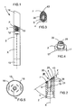
- the packaging and application device 1 represented in FIGS. 1 to 5 comprises a reservoir 2, of longitudinal axis X, containing the product P to be applied, possibly having a transparent portion 3 allowing the user to see the product P .
- the product P is for example pasty or gelled, having a viscosity such that it does not flow by capillarity when the device 1 is presented head down.
- the tank 2 may comprise, in the upper part, a support 4 for an applicator element comprising an applicator head 5 defining an application face 7 intended to come at least partially in contact with the region to be treated.
- the support 4 is traversed by at least one channel 10 for supplying the application face 7 with product.
- the product P can be forced to flow through the feed channel 10 by means of a piston 12 which is screwed onto a threaded rod 13 and which can move in translation in the container 2 when the threaded rod 13 is rotated by means of a control button 15 located in the lower part of the container.
- the container 2 may have a tubular body of non-circular cross section, for example oval.
- the applicator head 5 may be protected, in the absence of use, by a closure cap 16 which can be fixed on the receptacle 2.
- the application face 7 extends obliquely, being generally inclined in the absence of stress of an angle ⁇ with respect to the longitudinal axis X of the tank 2, the angle ⁇ being for example between 10 and 90 °, preferably between 25 ° and 65 °, more preferably between 35 ° and 40 °.
- the rotation of the control knob 15 can be carried out in increments, the reservoir 2 comprising for example, in the lower part, a plurality of tabs 17 arranged around the rod 13, against which two diametrically opposed rubbers 18 can be applied. 15 which can be seen in Figure 5.
- the latter may comprise a central shaft 19 ribbed, arranged to engage in a housing groove 20 provided at the lower end of the rod 13, to ensure a transmission of torque between the control knob 15 and the rod 13.
- the applicator head 5 comprises at least one cantilevered portion 25.
- the cantilevered configuration of the portion 25 is obtained by a flexible portion 21 of the applicator head 5 and by the configuration of the support 4.
- the portion 21 has a flexibility to change the orientation of the portion 25 relative to the longitudinal axis X during use.
- the orientation of the portion 25 is for example modified when it is subjected to stress, being for example manually brought against a surface of the body to be made up, for example the lips.
- the flexible portion 21 is formed near the reservoir 2 at a distance from a free distal end of the application face 7.
- the portion 25 extends above the support 4 by defining with the latter a gap 26 allowing a flexion, for example according to the arrow F of FIG. 2, towards the support 4.
- the portion 25 extends for example opposite a portion 22 of the support 4 having a recess, or a slope less than the inclination, out of stress, of the portion 25 relative to the axis X, as illustrated in FIG. 30.
- the width of the gap 26 is for example a few tenths of millimeters, or even a few millimeters.
- the cantilevered portion 25 may define only a fraction of the periphery of the application face 7 or all of this periphery, as illustrated.
- the gap 26 may have an annular shape, extending all around a hollow tip 30 of the applicator element, for mounting the applicator head on the container 2, and communicating with the supply channel 10 to bring the product to the application face 7.
- the flexibility of the cantilevered portion 25 may be related to the choice of the material used to make the applicator head and / or to the presence thereon of at least one hinge zone or a hinge zone. weakening.
- the applicator head 5 can be made in one piece by molding material, in particular an elastomer, with the endpiece 30.
- the latter can be fixed on the tank 2 in various ways, for example by snapping, force fitting, screwing, gluing or welding.
- the applicator element can be made at least partially with the reservoir 2, for example with the support 4, by injection molding of material or bi-injection.
- the tip 30 opens out onto a cavity 35 of the applicator head 5 which is open on the application face 7.
- This cavity 35 is for example unique and entirely surrounded by the application face 7.
- the cavity 35 extends for example all around the axis of the reservoir and opens permanently on the application face 7 without the intermediary of a valve.
- the applicator head 5 is advantageously flocked at least on the application face 7, as can be seen in particular in FIG.
- the applicator head 5 can also be flocked around its periphery, or even on the underside of the cantilevered portion 25.
- the flocking is for example carried out with bristles longer than 1 mm, for example equal to 1.2 mm, so that the end of the flocking hairs defines a plane distinct from the plane according to which the cavity.
- the user can turn the control knob 15 so as to raise the piston 12 and bring the product P on the application face 7 through the cavity 35.
- the product P can be spread, especially on the lips, in a relatively homogeneous, precise and comfortable manner.
- the channel inside the nozzle 30 opens out on the cavity 35 through a grid 40 which can slow down the flow of product P.
- the applicator head 5 may present, in top view, a tapered shape as seen in FIG. 3, with a tip 43, which is for example located at the upper end of the application face 7.
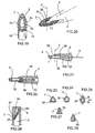
- FIGS. 8 to 26 It can be seen in FIGS. 8 to 26 that various shapes can be given to both the reservoir 2 and the application element.
- the tank 2 may comprise a neck 50 and the end piece 30 may be arranged to be fixed externally on the neck 50.
- the applicator head 5 may protrude laterally from the reservoir 2 when it is observed along the axis X, of a distance d that can be constant or not when moving around the X axis.
- the distance d is for example greater than or equal to 1 mm, or even 2 or 3 mm, or even more.
- the end piece 30 can also be engaged in an annular groove 51 of the reservoir 2, as illustrated in FIG. 9, the neck 50 being for example surrounded by an outer skirt 54 coming from at least partially covering the tip 30 at the outside.
- FIG. 10 illustrates the possibility of producing on the applicator head 5 a hinge zone 55 at the base of the cantilevered portion 25, so as to increase its flexibility relative to the endpiece 30.
- the hinge zone 55 may extend annularly around the tip 30, being formed for example by a groove 56 present on the underside of the applicator head 5.
- FIG. 11 illustrates another embodiment in which the applicator element is snap-fastened on the reservoir 2 and in which the outer surface of the nozzle 30 is part of the continuity of the external surface of the reservoir. 2.
- the applicator head 5 can come, by its underside, and optionally by flocking, in contact with the container 2, except for the cantilevered portion 25 which projects beyond the reservoir 2, as shown in FIG. 12 .
- the periphery of the applicator head 5 does not substantially exceed the reservoir 2 when it is observed along the X axis and the endpiece 30 is received in an annular groove 58 of the reservoir 2, delimited radially by a tubular skirt 60 whose apex is at a distance from the underside of the cantilevered portion 25.
- FIG. 14 illustrates in particular the possibility of producing the applicator element with at least one sealing lip 65 engaging on the reservoir 2 to ensure a tight fitting of the applicator element on the reservoir 2.
- the cantilever portion 25 may extend laterally only on one side of the tank 2, as shown in FIG.
- FIG. 16 shows an applicator head comprising, like that of FIG. 10, a weakened area 55, the dimensions of the cantilevered portion 25 nevertheless being different.
- FIG. 17 illustrates the possibility for the cavity 35 to have an outwardly flared shape, the cavity 35 being able to be flocked or not internally.
- the tip 30 may or may not be inclined relative to the cantilever portion 25 of the applicator head.
- connection of the end piece 30 to the applicator head can take place in a central region thereof or in an eccentric manner.
- the tip 30 may be sufficiently flexible, regardless of how the applicator head 5 is made, so that it can pivot about two axes A and B perpendicular to each other and perpendicular to the axis C of the tip 30.
- the cavity 35 which opens onto the application face 7 can be supplied with product by its side which is opposite to the application face 7, which is the case of the examples which have just been described.
- the supply of the cavity 35 may be effected by an orifice 70 which opens laterally into the cavity 35, the latter being through.
- Such a configuration may be useful in particular when the applicator element is mounted at the end of a reservoir with the Z axis of the cavity 35 oriented substantially perpendicular to the longitudinal axis of the reservoir 2, as illustrated in the figures. 20 and 21.
- the applicator head 5 may comprise two branches 73 and 74 which meet at their two ends and which define the cavity 35 between them.
- the longitudinal axes of the branches 73 and 74 may extend in a plane parallel to the X axis, for example.
- the branches 73 and 74 and / or the cavity 35 may be at least partially covered by an advance 80 of the tank 2.
- This advance 80 may extend to a non-zero distance of the branches 73 and 74, so as to provide a gap 82 therewith.
- This gap 82 may allow flexibility of the applicator head 5 in a direction substantially parallel to the Z axis.
- the width of the gap 82 may correspond substantially to the height of the flocking, for example.
- the arrival of product on the application face 7, which may be the face of the applicator head 5 opposite the advance 80, can be performed as in the illustrated example by means of a light 100 of the nozzle 30, the latter serving to fix the applicator element on the reservoir 2.
- the arrival of the product may be effected by a flow thereof outside the application element, for example in a channel formed between the applicator head 5 and the advanced 80, the endpiece 30 being for example full or nonexistent.
- the reservoir 2 comprises two advances 80 and 84 disposed on either side of the applicator head 5. These advances 80 and 84 may be symmetrical or non-symmetrical relative to one another. at a median plane for the tank 2.
- the application face 7 may have various shapes, as well as the cavity 35, as can be seen in FIGS. 23 to 27.
- the contour of the application face 7 may in particular be generally triangular, as shown in FIG. 23, circular as shown in FIG. 24 or oblong, in particular oval, as represented in FIG. 25.
- the application face may have a pear-shaped contour.
- the cavity 35 may have an opening through which it opens on the application face 7, of generally polygonal shape, in particular triangular or square as shown in FIGS. 23 and 26 respectively, circular as shown in FIG. 24, or oblong, in particular oval, as shown in FIG. 25, or even in the form of a slot, as illustrated in FIG. 27.
- the cavity 35 may define an outlet orifice of the product on the application face having a larger dimension m greater than or greater than equal to 2 mm and / or less than 5 mm, being for example equal to 3 mm.
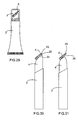
- the application face 7 may also have a contour having, when viewed from above, a variable width, for example passing through a minimum between its upper and lower ends, as illustrated in FIG. 27.
- the packaging and application device may or may not comprise a removable closure member and it may for example comprise a hollow sealing pin 90 whose lower end 91 is applied against the application face 7 around of the cavity 35, as shown in FIG. 28, so as to reduce the risk Product flow outwardly on the application face 7.
- the sealing pin 90 can engage the supply channel 10 to seal it.
- the tank 2 may comprise a rigid or flexible wall and for example be in the form of a flexible tube, as shown in Figure 29. To distribute the product, the user then presses on the wall of the tube.
- the applicator head 5 may have a thickness which decreases towards its upper end.
- FIG. 30 also shows the gap 26 formed with the support 4 and in FIG. 31 the cantilevered portion 25 that protrudes laterally upwards from the support 4.
- the applicator head can be made in many other ways.
- the supply side of the application face can be made with a permanent communication or not between the application face and the inside of the tank.
- the reservoir may be equipped with a pump or a valve, the applicator element being able to be secured to a control member to actuate to cause the dispensing of a dose of product.
- the latter can be contained in a flexible pouch protected from the air, if necessary.
- the applicator head may be made of a material loaded with magnetic particles in order to have magnetic properties.
Abstract
Description
La présente invention concerne les dispositifs de conditionnement et d'application comportant un réservoir contenant au moins un produit à distribuer et un élément d'application solidaire du réservoir au moins durant l'application.The present invention relates to packaging and application devices comprising a reservoir containing at least one product to be dispensed and an application element integral with the reservoir at least during the application.
Le brevet
Le brevet
Par ailleurs, la demande internationale
Les dispositifs connus pour le maquillage des lèvres n'offrent pas entière satisfaction.Known devices for lip makeup do not offer complete satisfaction.
En particulier, le produit peut s'accumuler pendant l'application sur le pourtour de l'élément d'application, ce qui peut conduire à un résultat de maquillage qui n'est pas aussi homogène que souhaitable, notamment avec des produits très colorés dont l'aspect est très dépendant de la qualité du dépôt formé sur les lèvres.In particular, the product can accumulate during the application on the periphery of the application element, which can lead to a makeup result that is not as homogeneous as desirable, especially with very colored products including the appearance is very dependent on the quality of the deposit formed on the lips.
Il existe par conséquent un besoin pour améliorer encore les dispositifs de conditionnement et d'application, afin notamment de réaliser un maquillage de la peau ou des lèvres plus homogène.There is therefore a need to further improve the packaging and application devices, in particular to achieve a makeup of the skin or lips more homogeneous.
Il existe également un besoin pour accroître le confort du maquillage, des lèvres notamment.There is also a need to increase the comfort of makeup, including lips.
L'invention vise à répondre à tout ou partie de ces besoins.The invention aims to meet all or part of these needs.
Elle y parvient grâce à un dispositif de conditionnement et d'application d'au moins un produit cosmétique, y compris de soin, comportant :
- un réservoir contenant le produit à distribuer,
- un élément d'application comportant une tête applicatrice solidaire du réservoir au moins durant l'application, présentant une face d'application destinée à venir au contact de la région à traiter, et comportant une cavité débouchant sur la face d'application,
- au moins un canal d'alimentation de la face d'application en produit provenant du réservoir, la tête applicatrice comportant :
- au moins une portion s'étendant en porte-à-faux jusqu'à la périphérie de la tête applicatrice et définissant au moins partiellement la face d'application.
- a reservoir containing the product to be dispensed,
- an applicator element comprising an applicator head secured to the reservoir at least during application, having an application face intended to come in contact with the region to be treated, and having a cavity opening on the application face,
- at least one feed channel of the product application face from the reservoir, the applicator head comprising:
- at least one portion extending cantilevered to the periphery of the applicator head and at least partially defining the application face.
Grâce à la présence de la cavité et de la portion en porte-à-faux, la tête applicatrice présente à la fois souplesse et capacité à charger la région à maquiller en produit d'une manière relativement homogène. La cavité peut permettre la constitution d'une réserve de produit et peut également servir à récupérer le produit. La cavité peut permettre de niveler la couche de produit déposée lors de l'application.Thanks to the presence of the cavity and the cantilevered portion, the applicator head has both flexibility and ability to charge the region to make up product in a relatively homogeneous manner. The cavity may allow the constitution of a stock of product and may also serve to recover the product. The cavity can be used to level the layer of product deposited during application.
La portion en porte-à-faux peut être obtenue par une portion flexible de la tête applicatrice et une configuration du réservoir telle que la flexibilité de cette portion permette de modifier l'orientation d'une portion au moins de la face d'application lorsque cette dernière portion est soumise à une contrainte, notamment lorsqu'elle est amenée manuellement contre une surface à maquiller, notamment les lèvres.The cantilevered portion may be obtained by a flexible portion of the applicator head and a configuration of the reservoir such that the flexibility of this portion makes it possible to modify the orientation of at least a portion of the application face when this last portion is subjected to stress, especially when it is manually brought against a surface to make up, including the lips.
La portion flexible peut avantageusement être formée à proximité du réservoir, à distance d'une extrémité distale libre de la face d'application.The flexible portion may advantageously be formed near the reservoir, at a distance from a free distal end of the application face.
La portion de la face d'application dont l'orientation peut être modifiée peut être disposée en regard d'une partie du récipient présentant un décrochement ou une pente inférieure à l'inclinaison, hors contrainte, de cette portion relativement à l'axe longitudinal du récipient.The portion of the application face whose orientation can be modified can be arranged facing a portion of the container having a recess or a slope less than the inclination, excluding stress, of this portion relative to the longitudinal axis of the container.
La cavité peut être distincte d'une fente capillaire, ayant par exemple un diamètre compris entre 1 et 5 mm, de préférence d'environ 3 mm.The cavity may be distinct from a capillary slot, having for example a diameter of between 1 and 5 mm, preferably of approximately 3 mm.
La cavité peut être ovale.The cavity may be oval.
La tête applicatrice peut notamment permettre de déposer plusieurs couches de produit afin d'accroître la brillance des lèvres, par exemple.The applicator head may in particular allow to deposit several layers of product to increase the gloss of the lips, for example.
La tête applicatrice peut être floquée ou non.The applicator head can be flocked or not.
Lorsque la tête applicatrice est floquée, le flocage peut être avantageusement réalisé avec des poils de longueur supérieure à 1 mm, par exemple une longueur de 1,2 mm, de telle sorte que l'extrémité des poils de flocage définisse un plan distinct d'un plan dans lequel est définie la cavité.When the applicator head is flocked, the flocking can advantageously be performed with bristles longer than 1 mm, for example a length of 1.2 mm, so that the end of the flocking hairs defines a plane distinct from a plane in which the cavity is defined.
Lorsque la tête applicatrice est floquée, les poils peuvent être sensiblement identiques ou différents et mélangés.When the applicator head is flocked, the bristles may be substantially identical or different and mixed.
La portion en porte-à-faux est avantageusement flexible.The cantilever portion is advantageously flexible.
La portion en porte-à-faux peut définir tout le pourtour de la face d'application.The cantilever portion may define the entire periphery of the application face.
L'élément d'application peut comporter une zone amincie à la base de la portion en porte-à-faux, ce qui peut permettre à celle-ci de fléchir plus facilement.The application member may have a thinned area at the base of the cantilevered portion, which may allow it to flex more easily.
L'élément d'application peut comporter un embout de fixation au réservoir, cet embout pouvant être traversé par le canal d'alimentation. L'embout peut être relativement rigide ou non, pouvant être réalisé le cas échéant de manière à permettre à la tête applicatrice de pivoter autour d'au moins un axe, voire autour d'au moins deux axes perpendiculaires entre eux. L'élément d'application peut être moulé en au moins deux matériaux, l'un rigide l'autre flexible. L'embout peut être, par exemple, moulé dans le matériau flexible.The applicator element may comprise an attachment end to the reservoir, this endpiece being traversable by the feed channel. The tip may be relatively rigid or not, can be made if necessary so as to allow the applicator head to pivot about at least one axis, or around at least two axes perpendicular to each other. The application element can be molded into at least two materials, one rigid and the other flexible. The tip may be, for example, molded into the flexible material.
Dans un exemple de mise en oeuvre de l'invention, la cavité est traversante et le canal d'alimentation peut déboucher dans la cavité.In an exemplary implementation of the invention, the cavity is through and the supply channel can lead into the cavity.
La cavité, qui peut permettre l'accumulation d'une réserve de produit, peut être alimentée en produit par le côté opposé à la face d'application, ou en variante être alimentée en produit par un orifice latéral.The cavity, which can allow the accumulation of a supply of product, can be supplied with product from the opposite side to the application face, or alternatively be supplied with product through a lateral orifice.
La cavité peut avantageusement être non centrée relativement à la face d'application.The cavity may advantageously be non-centered relative to the application face.
Le réservoir peut comporter au moins une avancée recouvrant au moins partiellement l'élément d'application.The reservoir may comprise at least one advance covering at least partially the application element.
Un interstice peut être ménagé entre l'élément d'application et l'avancée, cette dernière étant par exemple sensiblement au contact d'un flocage éventuel de l'élément d'application.A gap may be provided between the application element and the advance, the latter being for example substantially in contact with any flocking of the application element.
L'avancée peut recouvrir au moins partiellement la cavité, le cas échéant.The advance may at least partially cover the cavity, if any.
La face d'application peut présenter une forme effilée, notamment vers le haut. Cela peut améliorer la précision du maquillage, notamment celui de la lèvre supérieure.The application face may have a tapered shape, especially upwards. This can improve the accuracy of makeup, especially that of the upper lip.
La face d'application peut présenter un contour piriforme.The application face may have a pear-shaped contour.
La face d'application peut être généralement plane ou concave ou convexe.The application face may be generally flat or concave or convex.
La face d'application peut s'étendre tout autour de l'axe du réservoir.The application face can extend all around the axis of the reservoir.
La face d'application peut s'étendre selon un plan, en l'absence de contrainte. Ce plan peut être orienté obliquement relativement au récipient, l'angle aigu formé entre l'axe longitudinal du récipient et la face d'application étant par exemple compris entre 10° et 90°, de préférence entre 25° et 65°, mieux entre 35° et 40°.The application face can extend in a plane, in the absence of stress. This plane can be oriented obliquely relative to the container, the acute angle formed between the longitudinal axis of the container and the application face being for example between 10 ° and 90 °, preferably between 25 ° and 65 °, better between 35 ° and 40 °.
Le réservoir peut comporter une paroi souple. Le réservoir peut encore comporter une paroi cylindrique rigide, dans laquelle peut coulisser un piston.The reservoir may comprise a flexible wall. The reservoir may also comprise a rigid cylindrical wall in which a piston can slide.
Le produit peut encore être contenu dans une poche souple, la distribution s'effectuant sans reprise d'air.The product can still be contained in a flexible pouch, the distribution being effected without air intake.
L'embout précité peut être centré ou excentré relativement à la tête applicatrice.The aforementioned tip may be centered or eccentric relative to the applicator head.
La face d'application peut s'étendre généralement obliquement par rapport à un axe longitudinal du réservoir.The application face may extend generally obliquely with respect to a longitudinal axis of the reservoir.
L'élément d'application peut être réalisé, hormis le flocage éventuel, en élastomère d'une seule pièce par moulage de matière.The application element can be made, except for flocking, elastomer in one piece by molding material.
La tête applicatrice peut être réalisée par exemple en silicone, nitrile, EPDM, PU, butyle, latex, en élastomère thermoplastique de styrène, d'éthylène, de PVC, de PU, de polyester, d'EVA, d'EPDM, etc., en SEBS ou l'un des élastomères connus sous les marques CARIFLEX, SANTOPRENE, HYTREL, PEBAX (polyéther blockamide).The applicator head can be made for example of silicone, nitrile, EPDM, PU, butyl, latex, thermoplastic elastomer styrene, ethylene, PVC, PU, polyester, EVA, EPDM, etc. , in SEBS or one of the elastomers known under the trade marks CARIFLEX, SANTOPRENE, HYTREL, PEBAX (polyether blockamide).
La tête applicatrice peut présenter des propriétés magnétiques, afin par exemple de conférer une orientation particulière à des particules magnétiques contenues dans le produit ou changer au moins une propriété du produit.The applicator head may have magnetic properties, for example to give a particular orientation to magnetic particles contained in the product or change at least one property of the product.
La cavité peut déboucher sur la face d'application par une ouverture de section supérieure à celle d'un orifice du réservoir par lequel le produit contenu dans le réservoir gagne la cavité.The cavity can lead to the application face by an opening of greater section than that of a tank orifice through which the product contained in the tank reaches the cavity.
Le réservoir peut contenir un produit pour le maquillage des lèvres.The reservoir may contain a product for lip makeup.
Le produit contenu dans le réservoir peut être pâteux ou gélifié, ayant par exemple une viscosité telle qu'il ne s'écoule pas par capillarité lorsque le réservoir qui le contient est présenté tête en bas.The product contained in the reservoir may be pasty or gelled, having for example a viscosity such that it does not flow by capillarity when the reservoir which contains it is presented upside down.
Le dispositif peut comporter un organe de fermeture ayant un picot d'obturation disposé de manière à fermer un orifice de sortie du produit sur la face d'application.The device may comprise a closure member having a closing pin arranged to close an outlet of the product on the application face.
Le picot est par exemple agencé pour s'engager dans le canal d'alimentation, afin de l'obturer ou pour s'appliquer sur la tête applicatrice tout autour de l'orifice de sortie du produit. Ce dernier peut présenter une plus grande dimension supérieure ou égale à 2 mm, pouvant présenter une forme quelconque, notamment ovale.The pin is for example arranged to engage in the feed channel, to seal or to apply to the applicator head all around the outlet of the product. The latter may have a larger dimension greater than or equal to 2 mm, which may have any shape, including oval.
La section interne de l'orifice de sortie du produit peut avoir une plus grande dimension, notamment un diamètre inférieur à 5 mm, par exemple.The inner section of the outlet of the product may have a larger dimension, such as a diameter of less than 5 mm.
L'invention pourra être mieux comprise à la lecture de la description détaillée qui va suivre, d'exemples de mise en oeuvre non limitatifs de celle-ci, et à l'examen du dessin annexé, sur lequel :
- la figure 1 représente en élévation, de façon schématique, un exemple de dispositif de conditionnement et d'application selon l'invention,
- la figure 2 est une coupe longitudinale partielle du dispositif de la figure 1,
- la figure 3 est une vue schématique selon la flèche III de la figure 2,
- la figure 4 représente de manière schématique, en perspective, l'extrémité inférieure du corps du récipient de la figure 1, le bouton de commande du piston étant enlevé,
- la figure 5 est une vue de dessus du bouton de manoeuvre du piston,
- la figure 6 est une vue analogue à la figure 2 d'une variante de réalisation,
- la figure 7 est une vue de dessus selon la flèche VII de la figure 6,
- les figures 8 à 11, 13, 14, 16 et 17 sont des coupes longitudinales et partielles de variantes de réalisation de l'applicateur,
- les figures 12 et 15 sont des vues en élévation, partielles, de variantes de réalisation,
- la figure 18 représente isolément, en vue de dessous, l'élément d'application,
- les figures 19 et 20 représentent de façon partielle, en perspective, d'autres exemples de têtes applicatrices,
- les figures 21 et 22 sont des coupes longitudinales, partielles et schématiques, de variantes de réalisation du dispositif,
- les figures 23 à 27 sont des vues de face de la tête applicatrice, selon d'autres variantes de réalisation,
- la figure 28 est une coupe longitudinale partielle d'un organe de fermeture, et
- les figures 29 à 31 représentent en élévation, avec coupe longitudinale partielle, d'autres variantes.
- FIG. 1 represents in elevation, schematically, an example of a packaging and application device according to the invention,
- FIG. 2 is a partial longitudinal section of the device of FIG. 1,
- FIG. 3 is a schematic view along arrow III of FIG. 2,
- FIG. 4 schematically shows, in perspective, the lower end of the body of the container of FIG. 1, the control knob of the piston being removed,
- FIG. 5 is a plan view of the piston operating knob,
- FIG. 6 is a view similar to FIG. 2 of an alternative embodiment;
- FIG. 7 is a view from above according to arrow VII of FIG. 6,
- FIGS. 8 to 11, 13, 14, 16 and 17 are longitudinal and partial sections of variant embodiments of the applicator,
- FIGS. 12 and 15 are partial elevational views of alternative embodiments,
- FIG. 18 represents in isolation, in a view from below, the application element,
- FIGS. 19 and 20 partially show, in perspective, other examples of applicator heads,
- FIGS. 21 and 22 are longitudinal, partial and schematic sections of alternative embodiments of the device,
- FIGS. 23 to 27 are front views of the applicator head, according to other embodiments,
- FIG. 28 is a partial longitudinal section of a closure member, and
- Figures 29 to 31 show in elevation, with partial longitudinal section, other variants.
Le dispositif de conditionnement et d'application 1 représenté aux figures 1 à 5 comporte un réservoir 2, d'axe longitudinal X, contenant le produit P à appliquer, ayant éventuellement une portion transparente 3 permettant à l'utilisateur d'apercevoir le produit P.The packaging and application device 1 represented in FIGS. 1 to 5 comprises a
Le produit P est par exemple pâteux ou gélifié, ayant une viscosité telle qu'il ne s'écoule pas par capillarité lorsque le dispositif 1 est présenté tête en bas.The product P is for example pasty or gelled, having a viscosity such that it does not flow by capillarity when the device 1 is presented head down.
Le réservoir 2 peut comporter, en partie supérieure, un support 4 pour un élément d'application comportant une tête applicatrice 5 définissant une face d'application 7 destinée à venir au moins partiellement au contact de la région à traiter.The
Le support 4 est traversé par au moins un canal 10 d'alimentation de la face d'application 7 en produit. Le produit P peut être forcé à s'écouler par le canal d'alimentation 10 grâce à un piston 12 qui est vissé sur une tige filetée 13 et qui peut se déplacer en translation dans le récipient 2 lorsque la tige filetée 13 est entraînée en rotation au moyen d'un bouton de commande 15 situé en partie inférieure du récipient.The
Le récipient 2 peut présenter un corps tubulaire de section transversale non circulaire, par exemple ovale.The
La tête applicatrice 5 peut être protégée, en l'absence d'utilisation, par un capuchon de fermeture 16 qui peut se fixer sur le récipient 2.The
Dans l'exemple considéré, la face d'application 7 s'étend de façon oblique, étant généralement inclinée en l'absence de contrainte d'un angle α par rapport à l'axe longitudinal X du réservoir 2, l'angle α étant par exemple compris entre 10 et 90°, de préférence entre 25° et 65°, encore mieux entre 35° et 40°.In the example considered, the
La rotation du bouton de commande 15 peut s'effectuer par incréments, le réservoir 2 comportant par exemple, en partie inférieure, une pluralité de languettes 17 disposées autour de la tige 13, contre lesquelles peuvent s'appliquer deux frotteurs 18 diamétralement opposés du bouton de commande 15, que l'on peut voir sur la figure 5. Ce dernier peut comporter un fût central 19 nervuré, agencé pour s'engager dans un logement rainuré 20 prévu à l'extrémité inférieure de la tige 13, afin d'assurer une transmission du couple entre le bouton de commande 15 et la tige 13.The rotation of the
La tête applicatrice 5 comporte au moins une portion en porte-à-faux 25.The
La configuration en porte-à-faux de la portion 25 est obtenue par une portion flexible 21 de la tête applicatrice 5 et par la configuration du support 4. La portion 21 présente une flexibilité permettant de modifier l'orientation de la portion 25 relativement à l'axe longitudinal X durant l'utilisation.The cantilevered configuration of the
L'orientation de la portion 25 est par exemple modifiée lorsque celle-ci est soumise à une contrainte, étant par exemple amenée manuellement contre une surface du corps à maquiller, par exemple les lèvres.The orientation of the
Dans l'exemple décrit, la portion flexible 21 est formée à proximité du réservoir 2 à distance d'une extrémité distale libre de la face d'application 7.In the example described, the
La portion 25 s'étend au-dessus du support 4 en définissant avec ce dernier un intervalle 26 autorisant une flexion par exemple selon la flèche F de la figure 2, en rapprochement du support 4.The
La portion 25 s'étend par exemple en regard d'une partie 22 du support 4 présentant un décrochement, ou une pente inférieure à l'inclinaison, hors contrainte, de la portion 25 relativement à l'axe X, comme illustré sur la figure 30.The
La largeur de l'intervalle 26 est par exemple de quelques dixièmes de millimètres, voire de quelques millimètres.The width of the
La portion en porte-à-faux 25 peut ne définir qu'une fraction du pourtour de la face d'application 7 ou la totalité de ce pourtour, comme illustré.The cantilevered
L'intervalle 26 peut présenter une forme annulaire, s'étendant tout autour d'un embout creux 30 de l'élément d'application, servant au montage de la tête applicatrice sur le récipient 2, et communiquant avec le canal d'alimentation 10 pour amener le produit vers la face d'application 7.The
La flexibilité de la portion en porte-à-faux 25 peut être liée au choix du matériau servant à réaliser la tête applicatrice et/ou à la présence sur celle-ci d'au moins une zone formant charnière ou d'une zone d'affaiblissement.The flexibility of the cantilevered
La tête applicatrice 5 peut être réalisée d'une seule pièce par moulage de matière, notamment d'un élastomère, avec l'embout 30.The
Ce dernier peut être fixé sur le réservoir 2 de diverses manières, par exemple par encliquetage, montage à force, vissage, collage ou soudage.The latter can be fixed on the
Le cas échéant, l'élément d'application peut être réalisé au moins partiellement avec le réservoir 2, par exemple avec le support 4, par moulage par injection de matière ou par bi-injection.If necessary, the applicator element can be made at least partially with the
Dans l'exemple de la figure 2, l'embout 30 débouche sur une cavité 35 de la tête applicatrice 5 qui est ouverte sur la face d'application 7.In the example of FIG. 2, the
Cette cavité 35 est par exemple unique et entièrement entourée par la face d'application 7.This
La cavité 35 s'étend par exemple tout autour de l'axe du réservoir et débouche de manière permanente sur la face d'application 7 sans l'intermédiaire d'une valve.The
La tête applicatrice 5 est avantageusement floquée au moins sur la face d'application 7, comme on le voit notamment sur la figure 3.The
La tête applicatrice 5 peut également être floquée sur son pourtour, voire également sur la face inférieure de la portion en porte-à-faux 25.The
Le flocage est par exemple réalisé avec des poils d'une longueur supérieure à 1 mm, par exemple égale à 1,2 mm, de telle sorte que l'extrémité des poils de flocage définisse un plan distinct du plan selon lequel s'étend la cavité.The flocking is for example carried out with bristles longer than 1 mm, for example equal to 1.2 mm, so that the end of the flocking hairs defines a plane distinct from the plane according to which the cavity.
Pour utiliser le dispositif 1, lorsque le produit P est à appliquer sur les lèvres, l'utilisateur peut tourner le bouton de commande 15 de façon à faire remonter le piston 12 et amener du produit P sur la face d'application 7 à travers la cavité 35.To use the device 1, when the product P is to be applied to the lips, the user can turn the
Le produit P peut être étalé, sur les lèvres notamment, d'une façon relativement homogène, précise et confortable.The product P can be spread, especially on the lips, in a relatively homogeneous, precise and comfortable manner.
Dans la variante des figures 6 et 7, le canal intérieur à l'embout 30 débouche sur la cavité 35 au travers d'une grille 40 qui peut freiner l'écoulement de produit P.In the variant of FIGS. 6 and 7, the channel inside the
La tête applicatrice 5 peut présenter, en vue de dessus, une forme effilée comme on le voit sur la figure 3, avec une pointe 43, laquelle est par exemple située à l'extrémité supérieure de la face d'application 7.The
On voit sur les figures 8 à 26 que l'on peut donner diverses formes tant au réservoir 2 qu'à l'élément d'application.It can be seen in FIGS. 8 to 26 that various shapes can be given to both the
Par exemple, comme illustré à la figure 8, le réservoir 2 peut comporter un col 50 et l'embout 30 peut être agencé pour se fixer extérieurement sur le col 50.For example, as illustrated in FIG. 8, the
On voit également sur cette figure qu'indépendamment de la manière dont l'élément d'application est fixé sur le réservoir 2, la tête applicatrice 5 peut déborder latéralement du réservoir 2 lorsque celui-ci est observé selon l'axe X, d'une distance d qui peut être constante ou non lorsque l'on se déplace autour de l'axe X.It can also be seen in this figure that regardless of how the applicator element is fixed on the
La distance d est par exemple supérieure ou égale à 1 mm, voire à 2 ou 3 mm, voire plus encore.The distance d is for example greater than or equal to 1 mm, or even 2 or 3 mm, or even more.
L'embout 30 peut encore être engagé dans une gorge annulaire 51 du réservoir 2, comme illustré à la figure 9, le col 50 étant par exemple entouré d'une jupe extérieure 54 venant recouvrir extérieurement au moins partiellement l'embout 30.The
On a illustré sur la figure 10 la possibilité de réaliser sur la tête applicatrice 5 une zone formant charnière 55 à la base de la portion en porte-à-faux 25, de façon à accroître sa flexibilité relativement à l'embout 30.FIG. 10 illustrates the possibility of producing on the applicator head 5 a
La zone formant charnière 55 peut s'étendre annulairement autour de l'embout 30, étant par exemple formée par une gorge 56 présente sur la face inférieure de la tête applicatrice 5.The
On a illustré à la figure 11 une autre réalisation dans laquelle l'élément d'application est fixé par encliquetage sur le réservoir 2 et dans laquelle la surface extérieure de l'embout 30 vient s'inscrire dans la continuité de la surface extérieure du réservoir 2.FIG. 11 illustrates another embodiment in which the applicator element is snap-fastened on the
La tête applicatrice 5 peut venir, par sa face inférieure, et le cas échéant par un flocage éventuel, au contact du récipient 2, sauf pour la portion en porte-à-faux 25 qui déborde du réservoir 2, comme illustré à la figure 12.The
Dans l'exemple de la figure 13, la périphérie de la tête applicatrice 5 ne dépasse pas sensiblement du réservoir 2 lorsque celui-ci est observé selon l'axe X et l'embout 30 est reçu dans une gorge annulaire 58 du réservoir 2, délimitée radialement par une jupe tubulaire 60 dont le sommet se situe à une certaine distance de la face inférieure de la portion en porte-à-faux 25.In the example of FIG. 13, the periphery of the
La figure 14 illustre notamment la possibilité de réaliser l'élément d'application avec au moins une lèvre d'étanchéité 65 venant s'engager sur le réservoir 2 pour assurer un montage étanche de l'élément d'application sur le réservoir 2.FIG. 14 illustrates in particular the possibility of producing the applicator element with at least one sealing
La portion en porte-à-faux 25 peut ne s'étendre latéralement que d'un seul côté du réservoir 2, comme illustré à la figure 15.The
La figure 16 représente une tête applicatrice comportant, tout comme celle de la figure 10, une zone affaiblie 55, les dimensions de la portion en porte-à-faux 25 étant néanmoins différentes.FIG. 16 shows an applicator head comprising, like that of FIG. 10, a weakened
On a illustré sur la figure 17 la possibilité pour la cavité 35 de présenter une forme évasée vers l'extérieur, la cavité 35 pouvant être floquée ou non intérieurement.FIG. 17 illustrates the possibility for the
L'embout 30 peut être ou non incliné par rapport à la portion en porte-à-faux 25 de la tête applicatrice.The
On voit sur la figure 18 que le raccordement de l'embout 30 à la tête applicatrice peut s'effectuer dans une région centrale de celle-ci ou de manière excentrée.It can be seen in FIG. 18 that the connection of the
Le cas échéant, l'embout 30 peut être suffisamment flexible, indépendamment de la manière dont est réalisée la tête applicatrice 5, pour que celle-ci puisse pivoter autour de deux axes A et B perpendiculaires entre eux et perpendiculaires à l'axe C de l'embout 30.If necessary, the
La cavité 35 qui débouche sur la face d'application 7 peut être alimentée en produit par son côté qui est opposé à la face d'application 7, ce qui est le cas des exemples qui viennent d'être décrits.The
En variante, comme illustré à la figure 19, l'alimentation de la cavité 35 peut s'effectuer par un orifice 70 qui débouche latéralement dans la cavité 35, cette dernière étant traversante.Alternatively, as shown in Figure 19, the supply of the
Une telle configuration peut être utile notamment lorsque l'élément d'application est monté à l'extrémité d'un réservoir avec l'axe Z de la cavité 35 orienté sensiblement perpendiculairement à l'axe longitudinal du réservoir 2, comme illustré sur les figures 20 et 21.Such a configuration may be useful in particular when the applicator element is mounted at the end of a reservoir with the Z axis of the
On voit sur ces figures que la tête applicatrice 5 peut comporter deux branches 73 et 74 qui se rejoignent à leurs deux extrémités et qui définissent entre elles la cavité 35. Les axes longitudinaux des branches 73 et 74 peuvent s'étendre dans un plan parallèle à l'axe X, par exemple.It can be seen from these figures that the
Les branches 73 et 74 et/ou la cavité 35 peuvent être au moins partiellement recouvertes par une avancée 80 du réservoir 2.The
Cette avancée 80 peut s'étendre à une distance non nulle des branches 73 et 74, de manière à ménager un intervalle 82 avec celles-ci. Cet intervalle 82 peut permettre une flexibilité de la tête applicatrice 5 dans une direction sensiblement parallèle à l'axe Z.This
La largeur de l'intervalle 82 peut correspondre sensiblement à la hauteur du flocage, par exemple.The width of the
L'arrivée de produit sur la face d'application 7, qui peut être la face de la tête applicatrice 5 opposée à l'avancée 80, peut s'effectuer comme dans l'exemple illustré au moyen d'une lumière 100 de l'embout 30, ce dernier servant à la fixation de l'élément d'application sur le réservoir 2.The arrival of product on the
En variante, l'arrivée du produit peut s'effectuer par un écoulement de celui-ci à l'extérieur de l'élément d'application, par exemple dans un canal formé entre la tête applicatrice 5 et l'avancée 80, l'embout 30 étant par exemple plein, voire inexistant.Alternatively, the arrival of the product may be effected by a flow thereof outside the application element, for example in a channel formed between the
Dans l'exemple de la figure 22, le réservoir 2 comporte deux avancées 80 et 84 disposées de part et d'autre de la tête applicatrice 5. Ces avancées 80 et 84 peuvent être symétriques ou non l'une de l'autre par rapport à un plan médian pour le réservoir 2.In the example of FIG. 22, the
La face d'application 7 peut présenter diverses formes, de même que la cavité 35, comme on peut le voir sur les figures 23 à 27.The
Le contour de la face d'application 7 peut notamment être généralement triangulaire, comme représenté sur la figure 23, circulaire comme représenté sur la figure 24 ou oblong, notamment ovale, comme représenté sur la figure 25. La face d'application peut présenter un contour piriforme.The contour of the
La cavité 35 peut présenter une ouverture par laquelle elle débouche sur la face d'application 7, de forme généralement polygonale, notamment triangulaire ou carrée comme représenté sur les figures 23 et 26 respectivement, circulaire comme représenté sur la figure 24, ou oblongue, notamment ovale, comme représenté sur la figure 25, voire sous la forme d'une fente, comme illustré sur la figure 27. La cavité 35 peut définir un orifice de sortie du produit sur la face d'application ayant une plus grande dimension m supérieure ou égale à 2 mm et/ou inférieure à 5 mm, étant par exemple égale à 3 mm.The
La face d'application 7 peut également présenter un contour ayant, lorsqu'observé de dessus, une largeur variable, passant par exemple par un minimum entre ses extrémités supérieure et inférieure, comme illustré sur la figure 27.The
Le dispositif de conditionnement et d'application peut comporter ou non un organe de fermeture amovible et celui-ci peut par exemple comporter un picot d'obturation creux 90 dont l'extrémité inférieure 91 vient s'appliquer contre la face d'application 7 autour de la cavité 35, comme illustré sur la figure 28, de façon à réduire le risque d'écoulement de produit vers l'extérieur sur la face d'application 7. En variante, le picot d'obturation 90 peut s'engager dans le canal d'alimentation 10 pour l'obturer.The packaging and application device may or may not comprise a removable closure member and it may for example comprise a
Le réservoir 2 peut comporter une paroi rigide ou souple et par exemple se présenter sous la forme d'un tube souple, comme illustré à la figure 29. Pour distribuer le produit, l'utilisateur appuie alors sur la paroi du tube.The
Dans les exemples des figures 30 et 31, on voit que la tête applicatrice 5 peut présenter une épaisseur qui diminue vers son extrémité supérieure.In the examples of Figures 30 and 31, we see that the
On voit également dans l'exemple de la figure 30 l'intervalle 26 formé avec le support 4 et sur la figure 31, la portion en porte-à-faux 25 qui déborde latéralement vers le haut du support 4.FIG. 30 also shows the
Bien entendu, l'invention n'est pas limitée aux exemples qui viennent d'être décrits.Of course, the invention is not limited to the examples which have just been described.
En particulier, on peut réaliser la tête applicatrice de nombreuses autres manières.In particular, the applicator head can be made in many other ways.
L'alimentation de la face d'application peut s'effectuer avec une communication permanente ou non entre la face d'application et l'intérieur du réservoir.The supply side of the application face can be made with a permanent communication or not between the application face and the inside of the tank.
Le réservoir peut être équipé d'une pompe ou d'une valve, l'élément d'application pouvant être solidaire d'un organe de commande à actionner pour provoquer la distribution d'une dose de produit. Ce dernier peut être contenu dans une poche souple à l'abri de l'air, le cas échéant.The reservoir may be equipped with a pump or a valve, the applicator element being able to be secured to a control member to actuate to cause the dispensing of a dose of product. The latter can be contained in a flexible pouch protected from the air, if necessary.
La tête applicatrice peut être réalisée dans une matière chargée en particules magnétiques, afin de présenter des propriétés magnétiques.The applicator head may be made of a material loaded with magnetic particles in order to have magnetic properties.
L'expression « comportant un » doit être comprise comme étant synonyme de « comportant au moins un », sauf si le contraire est spécifié.The expression "having one" shall be understood as being synonymous with "having at least one", unless the opposite is specified.
Claims (40)
Applications Claiming Priority (1)
| Application Number | Priority Date | Filing Date | Title |
|---|---|---|---|
| FR0651171A FR2899076B1 (en) | 2006-04-03 | 2006-04-03 | PACKAGING AND APPLICATION DEVICE |
Publications (3)
| Publication Number | Publication Date |
|---|---|
| EP1842448A2 true EP1842448A2 (en) | 2007-10-10 |
| EP1842448A3 EP1842448A3 (en) | 2011-01-12 |
| EP1842448B1 EP1842448B1 (en) | 2017-07-12 |
Family
ID=37216111
Family Applications (1)
| Application Number | Title | Priority Date | Filing Date |
|---|---|---|---|
| EP07300917.7A Not-in-force EP1842448B1 (en) | 2006-04-03 | 2007-04-03 | Packaging and application device |
Country Status (3)
| Country | Link |
|---|---|
| EP (1) | EP1842448B1 (en) |
| ES (1) | ES2641823T3 (en) |
| FR (1) | FR2899076B1 (en) |
Cited By (3)
| Publication number | Priority date | Publication date | Assignee | Title |
|---|---|---|---|---|
| FR3028156A1 (en) * | 2014-11-10 | 2016-05-13 | Oreal | DEVICE FOR PACKAGING AND APPLYING A COSMETIC PRODUCT |
| FR3028155A1 (en) * | 2014-11-10 | 2016-05-13 | Oreal | DEVICE FOR APPLYING A COSMETIC PRODUCT |
| WO2016189168A1 (en) * | 2015-05-28 | 2016-12-01 | L'oreal | Cosmetic applicator |
Citations (7)
| Publication number | Priority date | Publication date | Assignee | Title |
|---|---|---|---|---|
| US3032803A (en) * | 1960-10-12 | 1962-05-08 | Walshauser Joseph John | Applicator device |
| US6280108B1 (en) * | 1998-12-24 | 2001-08-28 | John B. Haining | Suntan lotion applicator |
| FR2805720A1 (en) * | 2000-03-03 | 2001-09-07 | Oreal | Cosmetic applicator comprises body containing pump and sliding cover with upper externally threaded neck with internal hemispherical housing in which applicator is housed |
| EP1169939A1 (en) * | 2000-06-28 | 2002-01-09 | L'oreal | Cosmetic applicator comprising two assembled parts, one of them being flock-coated |
| EP1440629A1 (en) * | 2003-01-23 | 2004-07-28 | L'oreal | Applicator for applying a substance on a part of the human body |
| EP1745717A2 (en) * | 2005-07-19 | 2007-01-24 | L'oreal | Applicator and device for storing and applying comprising such an applicator |
| EP1810712A1 (en) * | 2004-11-08 | 2007-07-25 | Mitsubishi Pencil Co., Ltd. | Liquid applicator |
-
2006
- 2006-04-03 FR FR0651171A patent/FR2899076B1/en not_active Expired - Fee Related
-
2007
- 2007-04-03 ES ES07300917.7T patent/ES2641823T3/en active Active
- 2007-04-03 EP EP07300917.7A patent/EP1842448B1/en not_active Not-in-force
Patent Citations (7)
| Publication number | Priority date | Publication date | Assignee | Title |
|---|---|---|---|---|
| US3032803A (en) * | 1960-10-12 | 1962-05-08 | Walshauser Joseph John | Applicator device |
| US6280108B1 (en) * | 1998-12-24 | 2001-08-28 | John B. Haining | Suntan lotion applicator |
| FR2805720A1 (en) * | 2000-03-03 | 2001-09-07 | Oreal | Cosmetic applicator comprises body containing pump and sliding cover with upper externally threaded neck with internal hemispherical housing in which applicator is housed |
| EP1169939A1 (en) * | 2000-06-28 | 2002-01-09 | L'oreal | Cosmetic applicator comprising two assembled parts, one of them being flock-coated |
| EP1440629A1 (en) * | 2003-01-23 | 2004-07-28 | L'oreal | Applicator for applying a substance on a part of the human body |
| EP1810712A1 (en) * | 2004-11-08 | 2007-07-25 | Mitsubishi Pencil Co., Ltd. | Liquid applicator |
| EP1745717A2 (en) * | 2005-07-19 | 2007-01-24 | L'oreal | Applicator and device for storing and applying comprising such an applicator |
Cited By (5)
| Publication number | Priority date | Publication date | Assignee | Title |
|---|---|---|---|---|
| FR3028156A1 (en) * | 2014-11-10 | 2016-05-13 | Oreal | DEVICE FOR PACKAGING AND APPLYING A COSMETIC PRODUCT |
| FR3028155A1 (en) * | 2014-11-10 | 2016-05-13 | Oreal | DEVICE FOR APPLYING A COSMETIC PRODUCT |
| WO2016189168A1 (en) * | 2015-05-28 | 2016-12-01 | L'oreal | Cosmetic applicator |
| FR3036594A1 (en) * | 2015-05-28 | 2016-12-02 | Oreal | COSMETIC APPLICATOR |
| US11490712B2 (en) | 2015-05-28 | 2022-11-08 | L'oreal | Cosmetic applicator |
Also Published As
| Publication number | Publication date |
|---|---|
| EP1842448B1 (en) | 2017-07-12 |
| FR2899076A1 (en) | 2007-10-05 |
| ES2641823T3 (en) | 2017-11-14 |
| FR2899076B1 (en) | 2008-07-04 |
| EP1842448A3 (en) | 2011-01-12 |
Similar Documents
| Publication | Publication Date | Title |
|---|---|---|
| CA2306328C (en) | Device for packaging and application of a product with a spinning component comprising a slit | |
| EP1557111B1 (en) | Applicator with an applying element mounted on a recipient containing a product to be applied | |
| EP1169939B1 (en) | Cosmetic applicator comprising two assembled parts, one of them being flock-coated | |
| EP0975526B1 (en) | Dispensing cap with improved tightness | |
| EP1336353B1 (en) | Applicator comprising an applicator element configured to apply a product to the skin | |
| EP1745717B1 (en) | Device for storing and applying a product | |
| EP0916469B1 (en) | Flow reducer device, especially for a container holding a cosmetic product and method for producing | |
| FR2951920A1 (en) | DEVICE FOR CONDITIONING AND APPLYING A COSMETIC PRODUCT ON LIP. | |
| FR2989256A1 (en) | DEVICE FOR PACKAGING AND APPLYING A COSMETIC OR CARE PRODUCT ON LIP | |
| EP2016855A1 (en) | Packaging and application device for applying a product to the skin or the lips | |
| EP1174190A1 (en) | Packaging and variable dosage dispensing device | |
| EP1797789B1 (en) | Applicator with a product reserve, in particular for nail varnish | |
| FR2882505A1 (en) | Pasty or creamy product e.g. sunscreen cream, storing, distributing and applying tube for skin, has hollow compartment including peripheral wall that is directly connected to shell end or supported by side wall at end of shell | |
| FR2884157A1 (en) | HEAD OF DISTRIBUTION | |
| FR2979099A1 (en) | PRODUCT DISPENSING HEAD FOR A CONTAINER AND ASSOCIATED DISTRIBUTION DEVICE | |
| FR2727609A1 (en) | Liquid or paste product applicator | |
| EP1842448B1 (en) | Packaging and application device | |
| FR2845875A1 (en) | DEVICE COMPRISING A MECHANISM FOR DRIVING A STICK OR A MOBILE PISTON IN A BASE PART | |
| FR3066682A1 (en) | SPOON-LIKE APPLICATOR | |
| FR3016274A1 (en) | SPINNING DEVICE WITH VARIABLE GEOMETRY WIPING LIP | |
| FR2883139A1 (en) | DEVICE FOR PACKAGING AND APPLYING A COSMETIC PRODUCT | |
| EP1834542B1 (en) | A packaging and applicator device | |
| FR3051642A1 (en) | ARTICULATED COSMETIC PRODUCT APPLICATOR AND ASSOCIATED PACKAGING AND APPLICATION ASSEMBLY | |
| EP2014569B1 (en) | Device for packaging and applying a cosmetic product | |
| FR3073373B1 (en) | HEAD OF APPLICATION AND DISTRIBUTION OF COSMETIC PRODUCT, AND ASSOCIATED PACKAGING DEVICE |
Legal Events
| Date | Code | Title | Description |
|---|---|---|---|
| PUAI | Public reference made under article 153(3) epc to a published international application that has entered the european phase |
Free format text: ORIGINAL CODE: 0009012 |
|
| 17P | Request for examination filed |
Effective date: 20070403 |
|
| AK | Designated contracting states |
Kind code of ref document: A2 Designated state(s): AT BE BG CH CY CZ DE DK EE ES FI FR GB GR HU IE IS IT LI LT LU LV MC MT NL PL PT RO SE SI SK TR |
|
| AX | Request for extension of the european patent |
Extension state: AL BA HR MK YU |
|
| PUAL | Search report despatched |
Free format text: ORIGINAL CODE: 0009013 |
|
| AK | Designated contracting states |
Kind code of ref document: A3 Designated state(s): AT BE BG CH CY CZ DE DK EE ES FI FR GB GR HU IE IS IT LI LT LU LV MC MT NL PL PT RO SE SI SK TR |
|
| AX | Request for extension of the european patent |
Extension state: AL BA HR MK RS |
|
| AKX | Designation fees paid |
Designated state(s): AT BE BG CH CY CZ DE DK EE ES FI FR GB GR HU IE IS IT LI LT LU LV MC MT NL PL PT RO SE SI SK TR |
|
| GRAP | Despatch of communication of intention to grant a patent |
Free format text: ORIGINAL CODE: EPIDOSNIGR1 |
|
| STAA | Information on the status of an ep patent application or granted ep patent |
Free format text: STATUS: GRANT OF PATENT IS INTENDED |
|
| RIC1 | Information provided on ipc code assigned before grant |
Ipc: A45D 34/04 20060101AFI20170113BHEP |
|
| INTG | Intention to grant announced |
Effective date: 20170206 |
|
| GRAS | Grant fee paid |
Free format text: ORIGINAL CODE: EPIDOSNIGR3 |
|
| GRAA | (expected) grant |
Free format text: ORIGINAL CODE: 0009210 |
|
| STAA | Information on the status of an ep patent application or granted ep patent |
Free format text: STATUS: THE PATENT HAS BEEN GRANTED |
|
| AK | Designated contracting states |
Kind code of ref document: B1 Designated state(s): AT BE BG CH CY CZ DE DK EE ES FI FR GB GR HU IE IS IT LI LT LU LV MC MT NL PL PT RO SE SI SK TR |
|
| REG | Reference to a national code |
Ref country code: GB Ref legal event code: FG4D Free format text: NOT ENGLISH |
|
| REG | Reference to a national code |
Ref country code: CH Ref legal event code: EP |
|
| REG | Reference to a national code |
Ref country code: AT Ref legal event code: REF Ref document number: 907512 Country of ref document: AT Kind code of ref document: T Effective date: 20170715 |
|
| REG | Reference to a national code |
Ref country code: IE Ref legal event code: FG4D Free format text: LANGUAGE OF EP DOCUMENT: FRENCH |
|
| REG | Reference to a national code |
Ref country code: DE Ref legal event code: R096 Ref document number: 602007051593 Country of ref document: DE |
|
| REG | Reference to a national code |
Ref country code: ES Ref legal event code: FG2A Ref document number: 2641823 Country of ref document: ES Kind code of ref document: T3 Effective date: 20171114 |
|
| REG | Reference to a national code |
Ref country code: NL Ref legal event code: MP Effective date: 20170712 |
|
| REG | Reference to a national code |
Ref country code: LT Ref legal event code: MG4D |
|
| REG | Reference to a national code |
Ref country code: AT Ref legal event code: MK05 Ref document number: 907512 Country of ref document: AT Kind code of ref document: T Effective date: 20170712 |
|
| PG25 | Lapsed in a contracting state [announced via postgrant information from national office to epo] |
Ref country code: FI Free format text: LAPSE BECAUSE OF FAILURE TO SUBMIT A TRANSLATION OF THE DESCRIPTION OR TO PAY THE FEE WITHIN THE PRESCRIBED TIME-LIMIT Effective date: 20170712 Ref country code: SE Free format text: LAPSE BECAUSE OF FAILURE TO SUBMIT A TRANSLATION OF THE DESCRIPTION OR TO PAY THE FEE WITHIN THE PRESCRIBED TIME-LIMIT Effective date: 20170712 Ref country code: NL Free format text: LAPSE BECAUSE OF FAILURE TO SUBMIT A TRANSLATION OF THE DESCRIPTION OR TO PAY THE FEE WITHIN THE PRESCRIBED TIME-LIMIT Effective date: 20170712 Ref country code: LT Free format text: LAPSE BECAUSE OF FAILURE TO SUBMIT A TRANSLATION OF THE DESCRIPTION OR TO PAY THE FEE WITHIN THE PRESCRIBED TIME-LIMIT Effective date: 20170712 Ref country code: AT Free format text: LAPSE BECAUSE OF FAILURE TO SUBMIT A TRANSLATION OF THE DESCRIPTION OR TO PAY THE FEE WITHIN THE PRESCRIBED TIME-LIMIT Effective date: 20170712 |
|
| PG25 | Lapsed in a contracting state [announced via postgrant information from national office to epo] |
Ref country code: IS Free format text: LAPSE BECAUSE OF FAILURE TO SUBMIT A TRANSLATION OF THE DESCRIPTION OR TO PAY THE FEE WITHIN THE PRESCRIBED TIME-LIMIT Effective date: 20171112 Ref country code: LV Free format text: LAPSE BECAUSE OF FAILURE TO SUBMIT A TRANSLATION OF THE DESCRIPTION OR TO PAY THE FEE WITHIN THE PRESCRIBED TIME-LIMIT Effective date: 20170712 Ref country code: BG Free format text: LAPSE BECAUSE OF FAILURE TO SUBMIT A TRANSLATION OF THE DESCRIPTION OR TO PAY THE FEE WITHIN THE PRESCRIBED TIME-LIMIT Effective date: 20171012 Ref country code: PL Free format text: LAPSE BECAUSE OF FAILURE TO SUBMIT A TRANSLATION OF THE DESCRIPTION OR TO PAY THE FEE WITHIN THE PRESCRIBED TIME-LIMIT Effective date: 20170712 Ref country code: GR Free format text: LAPSE BECAUSE OF FAILURE TO SUBMIT A TRANSLATION OF THE DESCRIPTION OR TO PAY THE FEE WITHIN THE PRESCRIBED TIME-LIMIT Effective date: 20171013 |
|
| REG | Reference to a national code |
Ref country code: FR Ref legal event code: PLFP Year of fee payment: 12 |
|
| REG | Reference to a national code |
Ref country code: DE Ref legal event code: R097 Ref document number: 602007051593 Country of ref document: DE |
|
| PG25 | Lapsed in a contracting state [announced via postgrant information from national office to epo] |
Ref country code: CZ Free format text: LAPSE BECAUSE OF FAILURE TO SUBMIT A TRANSLATION OF THE DESCRIPTION OR TO PAY THE FEE WITHIN THE PRESCRIBED TIME-LIMIT Effective date: 20170712 Ref country code: DK Free format text: LAPSE BECAUSE OF FAILURE TO SUBMIT A TRANSLATION OF THE DESCRIPTION OR TO PAY THE FEE WITHIN THE PRESCRIBED TIME-LIMIT Effective date: 20170712 Ref country code: RO Free format text: LAPSE BECAUSE OF FAILURE TO SUBMIT A TRANSLATION OF THE DESCRIPTION OR TO PAY THE FEE WITHIN THE PRESCRIBED TIME-LIMIT Effective date: 20170712 |
|
| PLBE | No opposition filed within time limit |
Free format text: ORIGINAL CODE: 0009261 |
|
| STAA | Information on the status of an ep patent application or granted ep patent |
Free format text: STATUS: NO OPPOSITION FILED WITHIN TIME LIMIT |
|
| PG25 | Lapsed in a contracting state [announced via postgrant information from national office to epo] |
Ref country code: EE Free format text: LAPSE BECAUSE OF FAILURE TO SUBMIT A TRANSLATION OF THE DESCRIPTION OR TO PAY THE FEE WITHIN THE PRESCRIBED TIME-LIMIT Effective date: 20170712 Ref country code: SK Free format text: LAPSE BECAUSE OF FAILURE TO SUBMIT A TRANSLATION OF THE DESCRIPTION OR TO PAY THE FEE WITHIN THE PRESCRIBED TIME-LIMIT Effective date: 20170712 |
|
| 26N | No opposition filed |
Effective date: 20180413 |
|
| PG25 | Lapsed in a contracting state [announced via postgrant information from national office to epo] |
Ref country code: SI Free format text: LAPSE BECAUSE OF FAILURE TO SUBMIT A TRANSLATION OF THE DESCRIPTION OR TO PAY THE FEE WITHIN THE PRESCRIBED TIME-LIMIT Effective date: 20170712 |
|
| PG25 | Lapsed in a contracting state [announced via postgrant information from national office to epo] |
Ref country code: MT Free format text: LAPSE BECAUSE OF FAILURE TO SUBMIT A TRANSLATION OF THE DESCRIPTION OR TO PAY THE FEE WITHIN THE PRESCRIBED TIME-LIMIT Effective date: 20170712 |
|
| PG25 | Lapsed in a contracting state [announced via postgrant information from national office to epo] |
Ref country code: MC Free format text: LAPSE BECAUSE OF FAILURE TO SUBMIT A TRANSLATION OF THE DESCRIPTION OR TO PAY THE FEE WITHIN THE PRESCRIBED TIME-LIMIT Effective date: 20170712 |
|
| REG | Reference to a national code |
Ref country code: CH Ref legal event code: PL |
|
| REG | Reference to a national code |
Ref country code: BE Ref legal event code: MM Effective date: 20180430 |
|
| REG | Reference to a national code |
Ref country code: IE Ref legal event code: MM4A |
|
| PG25 | Lapsed in a contracting state [announced via postgrant information from national office to epo] |
Ref country code: LU Free format text: LAPSE BECAUSE OF NON-PAYMENT OF DUE FEES Effective date: 20180403 |
|
| PG25 | Lapsed in a contracting state [announced via postgrant information from national office to epo] |
Ref country code: CH Free format text: LAPSE BECAUSE OF NON-PAYMENT OF DUE FEES Effective date: 20180430 Ref country code: LI Free format text: LAPSE BECAUSE OF NON-PAYMENT OF DUE FEES Effective date: 20180430 Ref country code: BE Free format text: LAPSE BECAUSE OF NON-PAYMENT OF DUE FEES Effective date: 20180430 |
|
| PG25 | Lapsed in a contracting state [announced via postgrant information from national office to epo] |
Ref country code: IE Free format text: LAPSE BECAUSE OF NON-PAYMENT OF DUE FEES Effective date: 20180403 |
|
| PGFP | Annual fee paid to national office [announced via postgrant information from national office to epo] |
Ref country code: SE Payment date: 20190416 Year of fee payment: 15 |
|
| PG25 | Lapsed in a contracting state [announced via postgrant information from national office to epo] |
Ref country code: TR Free format text: LAPSE BECAUSE OF FAILURE TO SUBMIT A TRANSLATION OF THE DESCRIPTION OR TO PAY THE FEE WITHIN THE PRESCRIBED TIME-LIMIT Effective date: 20170712 |
|
| PGFP | Annual fee paid to national office [announced via postgrant information from national office to epo] |
Ref country code: GB Payment date: 20200325 Year of fee payment: 14 |
|
| PG25 | Lapsed in a contracting state [announced via postgrant information from national office to epo] |
Ref country code: HU Free format text: LAPSE BECAUSE OF FAILURE TO SUBMIT A TRANSLATION OF THE DESCRIPTION OR TO PAY THE FEE WITHIN THE PRESCRIBED TIME-LIMIT; INVALID AB INITIO Effective date: 20070403 Ref country code: PT Free format text: LAPSE BECAUSE OF FAILURE TO SUBMIT A TRANSLATION OF THE DESCRIPTION OR TO PAY THE FEE WITHIN THE PRESCRIBED TIME-LIMIT Effective date: 20170712 |
|
| PG25 | Lapsed in a contracting state [announced via postgrant information from national office to epo] |
Ref country code: CY Free format text: LAPSE BECAUSE OF FAILURE TO SUBMIT A TRANSLATION OF THE DESCRIPTION OR TO PAY THE FEE WITHIN THE PRESCRIBED TIME-LIMIT Effective date: 20170712 |
|
| PGFP | Annual fee paid to national office [announced via postgrant information from national office to epo] |
Ref country code: FR Payment date: 20200312 Year of fee payment: 14 |
|
| PGFP | Annual fee paid to national office [announced via postgrant information from national office to epo] |
Ref country code: DE Payment date: 20200325 Year of fee payment: 14 |
|
| PGFP | Annual fee paid to national office [announced via postgrant information from national office to epo] |
Ref country code: IT Payment date: 20200312 Year of fee payment: 14 |
|
| REG | Reference to a national code |
Ref country code: ES Ref legal event code: FD2A Effective date: 20210826 |
|
| REG | Reference to a national code |
Ref country code: DE Ref legal event code: R119 Ref document number: 602007051593 Country of ref document: DE |
|
| GBPC | Gb: european patent ceased through non-payment of renewal fee |
Effective date: 20210403 |
|
| PG25 | Lapsed in a contracting state [announced via postgrant information from national office to epo] |
Ref country code: FR Free format text: LAPSE BECAUSE OF NON-PAYMENT OF DUE FEES Effective date: 20210430 Ref country code: GB Free format text: LAPSE BECAUSE OF NON-PAYMENT OF DUE FEES Effective date: 20210403 Ref country code: DE Free format text: LAPSE BECAUSE OF NON-PAYMENT OF DUE FEES Effective date: 20211103 |
|
| PG25 | Lapsed in a contracting state [announced via postgrant information from national office to epo] |
Ref country code: ES Free format text: LAPSE BECAUSE OF NON-PAYMENT OF DUE FEES Effective date: 20200404 |
|
| PG25 | Lapsed in a contracting state [announced via postgrant information from national office to epo] |
Ref country code: IT Free format text: LAPSE BECAUSE OF NON-PAYMENT OF DUE FEES Effective date: 20200403 |