EP1839966A1 - Device for mounting a safety belt tensioning device - Google Patents
Device for mounting a safety belt tensioning device Download PDFInfo
- Publication number
- EP1839966A1 EP1839966A1 EP07005984A EP07005984A EP1839966A1 EP 1839966 A1 EP1839966 A1 EP 1839966A1 EP 07005984 A EP07005984 A EP 07005984A EP 07005984 A EP07005984 A EP 07005984A EP 1839966 A1 EP1839966 A1 EP 1839966A1
- Authority
- EP
- European Patent Office
- Prior art keywords
- reinforcing element
- belt tensioning
- backrest
- tensioning device
- belt
- Prior art date
- Legal status (The legal status is an assumption and is not a legal conclusion. Google has not performed a legal analysis and makes no representation as to the accuracy of the status listed.)
- Granted
Links
Images


Classifications
-
- B—PERFORMING OPERATIONS; TRANSPORTING
- B60—VEHICLES IN GENERAL
- B60R—VEHICLES, VEHICLE FITTINGS, OR VEHICLE PARTS, NOT OTHERWISE PROVIDED FOR
- B60R22/00—Safety belts or body harnesses in vehicles
- B60R22/18—Anchoring devices
- B60R22/24—Anchoring devices secured to the side, door, or roof of the vehicle
-
- B—PERFORMING OPERATIONS; TRANSPORTING
- B60—VEHICLES IN GENERAL
- B60R—VEHICLES, VEHICLE FITTINGS, OR VEHICLE PARTS, NOT OTHERWISE PROVIDED FOR
- B60R22/00—Safety belts or body harnesses in vehicles
- B60R22/34—Belt retractors, e.g. reels
- B60R22/46—Reels with means to tension the belt in an emergency by forced winding up
- B60R22/4628—Reels with means to tension the belt in an emergency by forced winding up characterised by fluid actuators, e.g. pyrotechnic gas generators
Definitions
- the invention relates to a device for holding a belt tensioning device in the region of a pillar of a motor vehicle and a support element for a backrest of a rear seat, with a welded to a body part of the motor vehicle reinforcing element.
- Such a device is for example from the EP 1 449 747 A2 known.
- the belt tensioning device is mounted on a support plate.
- the reinforcing element is designed like a frame and has an opening for insertion of the belt tensioning device.
- the carrier plate is screwed to the reinforcing element and closes the opening.
- the carrier plate has a locking pin for supporting the backrest. This leads first to the fact that the backrest is either locked with the locking pin or is released from this and the backrest can be folded. Thus, the inclination angle of the backrest can not be adjusted.
- this design has a plurality of components which are complex to manufacture and assemble.
- the invention is based on the problem, a device of the type mentioned in such a way that it allows easy connection differently shaped support elements of the backrest and the belt tensioning device and is particularly inexpensive to produce.
- the reinforcing element has an upwardly open, the dimensions of the belt tensioning device corresponding receptacle that the belt tensioning device is attached directly to the reinforcing element.
- the device according to the invention requires no support plate for holding the belt tensioning device, since the belt tensioning device is connected directly to the reinforcing element. This contributes to the reduction of the components and thus to the reduction of the manufacturing costs of the device according to the invention.
- the installation of the belt tensioning device takes place in a particularly simple manner from above into the receptacle of the reinforcing element.
- holding forces of the belt tensioning device are introduced into the reinforcing element. This avoids that the connection of the belt tensioning device is loaded on the reinforcing element by forces acting on the backrest forces. This contributes to the further reduction of the manufacturing costs of the device according to the invention.
- Another advantage of this design is in that the belt tensioning device and the support element of the backrest can be designed in a particularly diverse manner.
- the device according to the invention is structurally particularly simple when the reinforcing element is U-shaped in cross-section in the belt tensioning device and when the belt tensioning device is attached to a base and when projecting from the base legs are fastened with their free ends to the body part of the motor vehicle ,
- Another advantage of this design is that the reinforcing element attached to the body part has a particularly high stability.
- the reinforcing element is made of sheet metal.
- the belt tensioning device could exclusively comprise a belt retractor.
- the device according to the invention allows a diverse design of the belt tensioning device, when the belt tensioning device comprises a structural unit of belt retractor and pyrotechnic element of a belt tensioner and when the structural unit is arranged in the upwardly open receptacle. This can be arranged depending on an intended equipment variant of the motor vehicle optionally belt tensioning devices with or without belt tensioner on the reinforcing element.
- connection of the reinforcing element to the body part has according to another advantageous Development of the invention has a particularly high stability, when the reinforcing element has a flange for connection to a wheel housing of the motor vehicle.
- connection of the reinforcing element to the body part, it contributes, according to another advantageous embodiment of the invention, when the flange is arranged directly on a holder of a strut opposite side of the wheel housing.
- This design has the advantage that the connection of the holder of the shock absorber in any case leads to a reinforcement of the body part, which can be supported particularly reliably on the backrest acting forces and holding forces of the belt tensioning device.
- the reinforcing element has an additional reinforcement.
- the additional reinforcement is formed as welded to the reinforcing element sheet.
- the attachment of the supporting element for the backrest to the reinforcing element is particularly simple according to another advantageous embodiment of the invention, when the support element of the backrest attached to the reinforcing element and the backrest facing arm has.
- the arm is screwed to the support element.
- a riveted connection can also be used.
- the backrest facing arm could directly support the backrest in one embodiment.
- the device according to the invention allows flexibility of the motor vehicle when an adjusting device for adjusting the angle of inclination of the backrest is arranged at the free end of the arm.
- the backrest be kept unrestrained and in another trim level, the adjustment allow adjustment of the angle of inclination of the backrest.
- FIG. 1 shows a partial area of a motor vehicle in the area of a pillar 1 and a wheel housing 2 of a rear left wheel with a device 3 for holding a belt tensioning device 4 a guide 6 held belt 7.
- the guide 6 is fixed to the column 1.
- the belt tensioning device 4 has a belt retractor 8 and a belt tensioner 9 with a pyrotechnic element 10.
- the belt tensioning device 4 is fastened directly via a connecting element 11 to a reinforcing element 12 made of sheet metal.
- the reinforcing element 12 has an upwardly open receptacle 13, in which the belt tensioning device 4 is inserted.
- On the reinforcing element 12 also a backrest 5 ab
- Koreander arm 14 is fastened by screws 15.
- the arm 14 holds with its free end an adjusting device 16 for adjusting the inclination angle of the backrest 5.
- the reinforcing element 12 has a first flange 17 for attachment to the wheel housing 2 of the motor vehicle and a second flange 18 for attachment to the column first
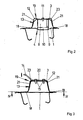
- Figures 2 and 3 show in sectional views through the device for holding the belt tensioning device 4 with adjacent components of the motor vehicle, that the reinforcing element 12 has a U-shaped portion 19.
- the belt tensioning device 4 is fixed, while protruding from the base 20 legs 21 have the second flange 18, with which the reinforcing element 12 is welded to the column 1.
- the reinforcing element 12 designed as an additional reinforcement 23 sheet is welded.
- Figure 4 shows the device 3 with adjacent components of the motor vehicle in a sectional view taken along the line III - III through Figure 2, and that the wheel housing 2 on its side opposite the reinforcing member 12 side holds a holder 22 for connecting a shock absorber, not shown.
- the holder 22 is welded to the wheel housing 2 on the first flange 17 of the reinforcing member 12 opposite side.
Abstract
Description
Die Erfindung betrifft eine Vorrichtung zur Halterung einer Gurtspanneinrichtung im Bereich einer Säule eines Kraftfahrzeuges und eines Abstützelementes für eine Rückenlehne einer Rücksitzbank, mit einem mit einem Karosserieteil des Kraftfahrzeuges verschweißten Verstärkungselement.The invention relates to a device for holding a belt tensioning device in the region of a pillar of a motor vehicle and a support element for a backrest of a rear seat, with a welded to a body part of the motor vehicle reinforcing element.
Eine solche Vorrichtung ist beispielsweise aus der
Der Erfindung liegt das Problem zugrunde, eine Vorrichtung der eingangs genannten Art so weiterzubilden, dass sie eine einfache Anbindung unterschiedlich gestalteter Abstützelemente der Rückenlehne und der Gurtspanneinrichtung ermöglicht und besonders kostengünstig herstellbar ist.The invention is based on the problem, a device of the type mentioned in such a way that it allows easy connection differently shaped support elements of the backrest and the belt tensioning device and is particularly inexpensive to produce.
Dieses Problem wird erfindungsgemäß dadurch gelöst, dass das Verstärkungselement eine nach oben offene, den Abmessungen der Gurtspanneinrichtung entsprechende Aufnahme hat, dass die Gurtspanneinrichtung unmittelbar an dem Verstärkungselement befestigt ist.This problem is inventively solved in that the reinforcing element has an upwardly open, the dimensions of the belt tensioning device corresponding receptacle that the belt tensioning device is attached directly to the reinforcing element.
Durch diese Gestaltung benötigt die erfindungsgemäße Vorrichtung keine Trägerplatte zur Halterung der Gurtspanneinrichtung, da die Gurtspanneinrichtung unmittelbar mit dem Verstärkungselement verbunden wird. Dies trägt zur Reduzierung der Bauteile und damit zur Verringerung der Fertigungskosten der erfindungsgemäßen Vorrichtung bei. Die Montage der Gurtspanneinrichtung erfolgt auf besonders einfache Weise von oben in die Aufnahme des Verstärkungselementes. Weiterhin werden dank der Erfindung Haltekräfte der Gurtspanneinrichtung in das verstärkungselement eingeleitet. Hierdurch wird vermieden, dass die Anbindung der Gurtspanneinrichtung an dem verstärkungselement durch auf die Rückenlehne einwirkende Kräfte belastet wird. Dies trägt zur weiteren Reduzierung der Fertigungskosten der erfindungsgemäßen Vorrichtung bei. Ein weiterer Vorteil dieser Gestaltung besteht darin, dass die Gurtspanneinrichtung und das Abstützelement der Rückenlehne besonders vielfältig gestaltet sein können.With this design, the device according to the invention requires no support plate for holding the belt tensioning device, since the belt tensioning device is connected directly to the reinforcing element. This contributes to the reduction of the components and thus to the reduction of the manufacturing costs of the device according to the invention. The installation of the belt tensioning device takes place in a particularly simple manner from above into the receptacle of the reinforcing element. Furthermore, thanks to the invention, holding forces of the belt tensioning device are introduced into the reinforcing element. This avoids that the connection of the belt tensioning device is loaded on the reinforcing element by forces acting on the backrest forces. This contributes to the further reduction of the manufacturing costs of the device according to the invention. Another advantage of this design is in that the belt tensioning device and the support element of the backrest can be designed in a particularly diverse manner.
Abstützkräfte der Rückenlehne werden gemäß einer vorteilhaften Weiterbildung der Erfindung zuverlässig abgestützt, wenn das Verstärkungselement das Abstützelement der Rückenlehne haltert.Supporting forces of the backrest are reliably supported according to an advantageous development of the invention, when the reinforcing element supports the support element of the backrest.
Die erfindungsgemäße Vorrichtung gestaltet sich konstruktiv besonders einfach, wenn das verstärkungselement im Querschnitt im Bereich der Gurtspanneinrichtung U-förmig gestaltet ist und wenn die Gurtspanneinrichtung an einer Basis befestigt ist und wenn von der Basis abstehende Schenkel mit ihren freien Enden an dem Karosserieteil des Kraftfahrzeuges befestigt sind. Ein weiterer Vorteil dieser Gestaltung besteht darin, dass das an dem Karosserieteil befestigte Verstärkungselement eine besonders hohe Stabilität aufweist. Vorzugsweise ist das Verstärkungselement aus Blech gefertigt.The device according to the invention is structurally particularly simple when the reinforcing element is U-shaped in cross-section in the belt tensioning device and when the belt tensioning device is attached to a base and when projecting from the base legs are fastened with their free ends to the body part of the motor vehicle , Another advantage of this design is that the reinforcing element attached to the body part has a particularly high stability. Preferably, the reinforcing element is made of sheet metal.
Die Gurtspanneinrichtung könnte beispielsweise in einer Ausführungsform ausschließlich einen Gurtaufroller aufweisen. Die erfindungsgemäße Vorrichtung ermöglicht jedoch eine vielfältige Gestaltung der Gurtspanneinrichtung, wenn die Gurtspanneinrichtung eine bauliche Einheit aus Gurtaufroller und pyrotechnischem Element eines Gurtstraffers aufweist und wenn die bauliche Einheit in der nach oben offenen Aufnahme angeordnet ist. Damit lassen sich in Abhängigkeit von einer vorgesehenen Ausstattungsvariante des Kraftfahrzeuges wahlweise Gurtspanneinrichtungen mit oder ohne Gurtstraffer an dem Verstärkungselement anordnen.For example, in one embodiment, the belt tensioning device could exclusively comprise a belt retractor. The device according to the invention, however, allows a diverse design of the belt tensioning device, when the belt tensioning device comprises a structural unit of belt retractor and pyrotechnic element of a belt tensioner and when the structural unit is arranged in the upwardly open receptacle. This can be arranged depending on an intended equipment variant of the motor vehicle optionally belt tensioning devices with or without belt tensioner on the reinforcing element.
Die Anbindung des Verstärkungselementes an dem Karosserieteil weist gemäß einer anderen vorteilhaften Weiterbildung der Erfindung eine besonders hohe Stabilität auf, wenn das Verstärkungselement einen Flansch zur Anbindung an einem Radgehäuse des Kraftfahrzeuges hat.The connection of the reinforcing element to the body part has according to another advantageous Development of the invention has a particularly high stability, when the reinforcing element has a flange for connection to a wheel housing of the motor vehicle.
Zur weiteren Erhöhung der Stabilität der Anbindung des Verstärkungselementes an dem Karosserieteil trägt es gemäß einer anderen vorteilhaften Weiterbildung der Erfindung bei, wenn der Flansch unmittelbar auf der einem Halter eines Federbeins gegenüberliegenden Seite des Radgehäuses angeordnet ist. Diese Gestaltung hat den Vorteil, dass die Anbindung des Halters des Federbeins ohnehin zu einer Verstärkung des Karosserieteils führt, wodurch auf die Rückenlehne einwirkende Kräfte und Haltekräfte der Gurtspanneinrichtung besonders zuverlässig abgestützt werden können.To further increase the stability of the connection of the reinforcing element to the body part, it contributes, according to another advantageous embodiment of the invention, when the flange is arranged directly on a holder of a strut opposite side of the wheel housing. This design has the advantage that the connection of the holder of the shock absorber in any case leads to a reinforcement of the body part, which can be supported particularly reliably on the backrest acting forces and holding forces of the belt tensioning device.
Zur weiteren Erhöhung der Stabilität der Anbindung des Verstärkungselements an dem Karosserieteil trägt es gemäß einer anderen vorteilhaften Weiterbildung der Erfindung bei, wenn das Verstärkungselement eine Zusatzverstärkung aufweist. Vorzugsweise ist die Zusatzverstärkung als mit dem verstärkungselement verschweißtes Blech ausgebildet.To further increase the stability of the connection of the reinforcing element to the body part, it contributes according to another advantageous development of the invention, when the reinforcing element has an additional reinforcement. Preferably, the additional reinforcement is formed as welded to the reinforcing element sheet.
Zur weiteren Erhöhung der Stabilität der Anbindung des Verstärkungselementes an dem Karosserieteil trägt es gemäß einer anderen vorteilhaften Weiterbildung der Erfindung bei, wenn ein zweiter Flansch seitlich neben der nach oben offenen Aufnahme angeordnet und an der Säule befestigt ist.To further increase the stability of the connection of the reinforcing element to the body part, it contributes according to another advantageous embodiment of the invention, when a second flange is arranged laterally next to the upwardly open receptacle and secured to the column.
Die Befestigung des Abstützelementes für die Rückenlehne an dem Verstärkungselement gestaltet sich gemäß einer anderen vorteilhaften Weiterbildung der Erfindung besonders einfach, wenn das Abstützelement der Rückenlehne einen an dem Verstärkungselement befestigten und der Rückenlehne zugewandten Arm hat. Vorzugsweise ist der Arm mit dem Abstützelement verschraubt. Alternativ kann auch eine Nietverbindung zum Einsatz kommen.The attachment of the supporting element for the backrest to the reinforcing element is particularly simple according to another advantageous embodiment of the invention, when the support element of the backrest attached to the reinforcing element and the backrest facing arm has. Preferably, the arm is screwed to the support element. Alternatively, a riveted connection can also be used.
Der der Rückenlehne zugewandte Arm könnte in einer Ausführungsform die Rückenlehne unmittelbar haltern. Die erfindungsgemäße Vorrichtung ermöglicht jedoch eine Flexibilität des Kraftfahrzeuges, wenn an dem freien Ende des Arms eine Verstelleinrichtung zur Verstellung des Neigungswinkels der Rückenlehne angeordnet ist. Damit kann durch eine entsprechende Gestaltung des Arms in einer Ausstattungsvariante die Rückenlehne unverstellbar gehalten sein und in einer anderen Ausstattungsvariante die Verstelleinrichtung eine Verstellung des Neigungswinkels der Rückenlehne ermöglichen.The backrest facing arm could directly support the backrest in one embodiment. However, the device according to the invention allows flexibility of the motor vehicle when an adjusting device for adjusting the angle of inclination of the backrest is arranged at the free end of the arm. Thus, by a corresponding design of the arm in a trim level, the backrest be kept unrestrained and in another trim level, the adjustment allow adjustment of the angle of inclination of the backrest.
Die Erfindung lässt verschiedene Ausführungsformen zu. Zur weiteren Verdeutlichung ihres Grundprinzips ist eine davon in der Zeichnung dargestellt und wird nachfolgend beschrieben. Die Zeichnung zeigt in
- Fig. 1
- einen Teilbereich eines Kraftfahrzeuges im Bereich einer Säule mit einer erfindungsgemäßen Vorrichtung,
- Fig. 2
- die erfindungsgemäße Vorrichtung aus
Figur 1 in einer Schnittdarstellung entlang der Linie II - II, - Fig. 3
- die erfindungsgemäße Vorrichtung aus
Figur 1 in einer Schnittdarstellung entlang der Linie III - III, - Fig. 4
- die erfindungsgemäße Vorrichtung aus
Figur 3 in einer Schnittdarstellung entlang der Linie IV - IV.
- Fig. 1
- a portion of a motor vehicle in the region of a column with a device according to the invention,
- Fig. 2
- 1 shows the device according to the invention in a sectional view along the line II-II,
- Fig. 3
- 1 shows the device according to the invention in a sectional view along the line III-III,
- Fig. 4
- the inventive device of Figure 3 in a sectional view taken along the line IV - IV.
Figur 1 zeigt einen Teilbereich eines Kraftfahrzeuges im Bereich einer als C-Säule ausgebildeten Säule 1 und eines Radgehäuses 2 eines hinteren linken Rades mit einer Vorrichtung 3 zur Halterung einer Gurtspanneinrichtung 4. Die Gurtspanneinrichtung 4 ist hinter einer Rückenlehne 5 einer Rücksitzbank angeordnet und hat einen von einer Führung 6 gehaltenen Gurt 7. Die Führung 6 ist an der Säule 1 befestigt. Die Gurtspanneinrichtung 4 weist einen Gurtaufroller 8 und einen Gurtstraffer 9 mit einem pyrotechnischen Element 10 auf. Die Gurtspanneinrichtung 4 ist unmittelbar über ein Verbindungselement 11 an einem aus Blech gefertigten Verstärkungselement 12 befestigt. Hierfür hat das Verstärkungselement 12 eine nach oben hin offene Aufnahme 13, in die die Gurtspanneinrichtung 4 eingesetzt ist. An dem Verstärkungselement 12 ist zudem ein die Rückenlehne 5 abstützender Arm 14 über Schrauben 15 befestigt. Der Arm 14 haltert mit seinem freien Ende eine Verstelleinrichtung 16 zur Verstellung des Neigungswinkels der Rückenlehne 5. Das Verstärkungselement 12 hat einen ersten Flansch 17 zur Befestigung an dem Radgehäuse 2 des Kraftfahrzeuges und einen zweiten Flansch 18 zur Befestigung an der Säule 1.FIG. 1 shows a partial area of a motor vehicle in the area of a
Die Figuren 2 und 3 zeigen in Schnittdarstellungen durch die Vorrichtung zur Halterung der Gurtspanneinrichtung 4 mit angrenzenden Bauteilen des Kraftfahrzeuges, dass das Verstärkungselement 12 einen U-förmigen Abschnitt 19 aufweist. An einer Basis 20 des U-förmigen Abschnitts 19 ist die Gurtspanneinrichtung 4 befestigt, während von der Basis 20 abstehende Schenkel 21 den zweiten Flansch 18 aufweisen, mit dem das Verstärkungselement 12 an der Säule 1 verschweißt ist. In dem Verstärkungselement 12 ist ein als Zusatzverstärkung 23 ausgebildetes Blech eingeschweißt.Figures 2 and 3 show in sectional views through the device for holding the
Figur 4 zeigt die Vorrichtung 3 mit angrenzenden Bauteilen des Kraftfahrzeuges in einer Schnittdarstellung entlang der Linie III - III durch Figur 2, und dass das Radgehäuse 2 an seiner dem Verstärkungselement 12 gegenüberliegenden Seite einen Halter 22 zur Anbindung eines nicht dargestellten Federbeins haltert. Der Halter 22 ist mit dem Radgehäuse 2 auf der dem ersten Flansch 17 des Verstärkungselementes 12 gegenüberliegenden Seite verschweißt.Figure 4 shows the
- 11
- Säulepillar
- 22
- Radgehäusewheel housing
- 33
- Vorrichtungcontraption
- 44
- Gurtspanneinrichtungbelt tensioning
- 55
- Rückenlehnebackrest
- 66
- Führungguide
- 77
- Gurtbelt
- 88th
- Gurtaufrollerretractor
- 99
- Gurtstrafferpretensioners
- 1010
- pyrotechnisches Elementpyrotechnic element
- 1111
- verbindungselementfastener
- 1212
- Verstärkungselementreinforcing element
- 1313
- Aufnahmeadmission
- 1414
- Armpoor
- 1515
- Schraubescrew
- 1616
- Verstelleinrichtungadjustment
- 17, 1817, 18
- Flanschflange
- 1919
- U-förmiger AbschnittU-shaped section
- 2020
- BasisBase
- 2121
- Schenkelleg
- 2222
- Halterholder
- 2323
- Zusatzverstärkungadditional reinforcement
Claims (11)
Applications Claiming Priority (1)
| Application Number | Priority Date | Filing Date | Title |
|---|---|---|---|
| DE102006013649A DE102006013649A1 (en) | 2006-03-24 | 2006-03-24 | Method for securing seat belt fastening especially for rear seat in vehicle has a chassis mounting bracket with seat belt fastening on the outside |
Publications (2)
| Publication Number | Publication Date |
|---|---|
| EP1839966A1 true EP1839966A1 (en) | 2007-10-03 |
| EP1839966B1 EP1839966B1 (en) | 2008-11-26 |
Family
ID=38109667
Family Applications (1)
| Application Number | Title | Priority Date | Filing Date |
|---|---|---|---|
| EP07005984A Active EP1839966B1 (en) | 2006-03-24 | 2007-03-23 | Device for mounting a safety belt tensioning device |
Country Status (3)
| Country | Link |
|---|---|
| EP (1) | EP1839966B1 (en) |
| AT (1) | ATE415319T1 (en) |
| DE (2) | DE102006013649A1 (en) |
Cited By (2)
| Publication number | Priority date | Publication date | Assignee | Title |
|---|---|---|---|---|
| FR2928320A1 (en) * | 2008-03-04 | 2009-09-11 | Peugeot Citroen Automobiles Sa | Safety belt roller fixing system for lower longeron of motor vehicle's body, has unique support comprising support portion with fixation units for fixing pretensioner and loop strand of safety belt to portion of safety belt roller |
| EP2181899A1 (en) | 2008-11-03 | 2010-05-05 | Peugeot Citroen Automobiles SA | Seatbelt attachment device and vehicle floor equipped with such a device. |
Families Citing this family (2)
| Publication number | Priority date | Publication date | Assignee | Title |
|---|---|---|---|---|
| CN108263335B (en) * | 2018-01-25 | 2021-05-04 | 重庆长安汽车股份有限公司 | Safety belt coiler support assembly |
| KR20220126110A (en) * | 2021-03-08 | 2022-09-15 | 현대자동차주식회사 | Seat belt mounting bracket mounting structure |
Citations (7)
| Publication number | Priority date | Publication date | Assignee | Title |
|---|---|---|---|---|
| EP0639485A1 (en) * | 1993-08-18 | 1995-02-22 | Adam Opel Ag | Fastening of a safety belt and its corresponding components |
| US5769456A (en) * | 1993-12-02 | 1998-06-23 | Autoliv Development Ab | Pre-fitted carrier unit for the functional parts of a safety belt system |
| US5863071A (en) * | 1998-04-08 | 1999-01-26 | Nissan Research & Development, Inc. | Seat belt anchor device for an automobile |
| DE20005145U1 (en) * | 2000-03-21 | 2000-08-10 | Trw Repa Gmbh | Seat belt system pre-assembled on the B-pillar |
| EP1449747A2 (en) * | 2003-02-22 | 2004-08-25 | Adam Opel Ag | Reinforcement means in the region of the C-pillar of a vehicle body |
| EP1498345A2 (en) * | 2003-07-18 | 2005-01-19 | Audi Ag | Pillar of a vehicle chassis |
| FR2862034A1 (en) * | 2003-11-03 | 2005-05-13 | Volkswagen Ag | Passenger restraint system for motor vehicle, has sheet metal section mounting seat belt retractor on upper section of backrest of rear seat, in zone of inner wall of vehicle, so that safety belt is directly retracted by passenger |
Family Cites Families (2)
| Publication number | Priority date | Publication date | Assignee | Title |
|---|---|---|---|---|
| GB2315983A (en) * | 1996-08-08 | 1998-02-18 | Alliedsignal Sistemi Di Sicure | Seat belt pretensioner arming bracket |
| DE10257957B4 (en) * | 2002-12-12 | 2019-06-27 | Volkswagen Ag | Rear restraint system on motor vehicles |
-
2006
- 2006-03-24 DE DE102006013649A patent/DE102006013649A1/en not_active Withdrawn
-
2007
- 2007-03-23 DE DE502007000248T patent/DE502007000248D1/en active Active
- 2007-03-23 AT AT07005984T patent/ATE415319T1/en not_active IP Right Cessation
- 2007-03-23 EP EP07005984A patent/EP1839966B1/en active Active
Patent Citations (7)
| Publication number | Priority date | Publication date | Assignee | Title |
|---|---|---|---|---|
| EP0639485A1 (en) * | 1993-08-18 | 1995-02-22 | Adam Opel Ag | Fastening of a safety belt and its corresponding components |
| US5769456A (en) * | 1993-12-02 | 1998-06-23 | Autoliv Development Ab | Pre-fitted carrier unit for the functional parts of a safety belt system |
| US5863071A (en) * | 1998-04-08 | 1999-01-26 | Nissan Research & Development, Inc. | Seat belt anchor device for an automobile |
| DE20005145U1 (en) * | 2000-03-21 | 2000-08-10 | Trw Repa Gmbh | Seat belt system pre-assembled on the B-pillar |
| EP1449747A2 (en) * | 2003-02-22 | 2004-08-25 | Adam Opel Ag | Reinforcement means in the region of the C-pillar of a vehicle body |
| EP1498345A2 (en) * | 2003-07-18 | 2005-01-19 | Audi Ag | Pillar of a vehicle chassis |
| FR2862034A1 (en) * | 2003-11-03 | 2005-05-13 | Volkswagen Ag | Passenger restraint system for motor vehicle, has sheet metal section mounting seat belt retractor on upper section of backrest of rear seat, in zone of inner wall of vehicle, so that safety belt is directly retracted by passenger |
Cited By (2)
| Publication number | Priority date | Publication date | Assignee | Title |
|---|---|---|---|---|
| FR2928320A1 (en) * | 2008-03-04 | 2009-09-11 | Peugeot Citroen Automobiles Sa | Safety belt roller fixing system for lower longeron of motor vehicle's body, has unique support comprising support portion with fixation units for fixing pretensioner and loop strand of safety belt to portion of safety belt roller |
| EP2181899A1 (en) | 2008-11-03 | 2010-05-05 | Peugeot Citroen Automobiles SA | Seatbelt attachment device and vehicle floor equipped with such a device. |
Also Published As
| Publication number | Publication date |
|---|---|
| DE502007000248D1 (en) | 2009-01-08 |
| ATE415319T1 (en) | 2008-12-15 |
| EP1839966B1 (en) | 2008-11-26 |
| DE102006013649A1 (en) | 2007-09-27 |
Similar Documents
| Publication | Publication Date | Title |
|---|---|---|
| EP0765252B1 (en) | Bench seat for motor vehicles, in particular camping cars | |
| EP1216895B1 (en) | Mounting bracket | |
| DE10345482A1 (en) | Vehicle seat arrangement with energy absorption part | |
| DE102018213279A1 (en) | Load-bearing structural part for a vehicle seat | |
| EP1839966B1 (en) | Device for mounting a safety belt tensioning device | |
| DE102018129034B4 (en) | Front body structure for a motor vehicle | |
| EP3274213B1 (en) | Adaptor assembly für a vehicle seat and vehicle seat | |
| DE102006009601B3 (en) | Fuel tank holding structure for commercial vehicle has brackets attached to chassis and retaining straps with clamps | |
| EP3508373B1 (en) | Belt frame for a vehicle seat | |
| WO2015082537A1 (en) | Seat component with seat belt buckle device | |
| EP1149723B1 (en) | Stabilising device for a dash board arranged position-adjustable in a vehicle | |
| DE102019205307B4 (en) | Belt retractor for mounting in a vehicle seat | |
| EP1712385B1 (en) | Vertical guide rail with fixation means | |
| WO2008083990A1 (en) | Disconnected pedal unit in a mine-proof, especially military vehicle | |
| DE10353449B4 (en) | Bearing, in particular center bearing, for the pivotable articulation of seat backs in a vehicle, in particular for the pivotable articulation of separately convertible seat backs of a rear seat of a motor vehicle | |
| EP3366511A1 (en) | Belt frame for a vehicle seat or a vehicle seat bench | |
| DE102006046877B4 (en) | Mountable bulkhead between the passenger compartment and trunk | |
| EP1132264B1 (en) | Height adjustment device for a vehicle safety belt system | |
| DE102019004287A1 (en) | Anchoring arrangement for anchoring a belt anchoring element for a seat belt on a vehicle component | |
| DE102009018330B3 (en) | Fastening arrangement for reversible belt tensioner, has belt retractor which is driven by electric motor on vehicle, where electric motor and belt retractor are arranged on support frame, and belt tensioner is fixed on vehicle | |
| DE102008024429B4 (en) | support/mounting element | |
| WO2015028459A1 (en) | Seat structure, vehicle seat and method for producing a vehicle seat | |
| EP2700554A1 (en) | Device for self-supporting fastening of a passenger seat and method for manufacturing such a device and a railcar body | |
| DE102021106683B4 (en) | Belt retractor with an electrically operated blocking device | |
| DE202017006707U1 (en) | Belt frame for a vehicle seat |
Legal Events
| Date | Code | Title | Description |
|---|---|---|---|
| PUAI | Public reference made under article 153(3) epc to a published international application that has entered the european phase |
Free format text: ORIGINAL CODE: 0009012 |
|
| AK | Designated contracting states |
Kind code of ref document: A1 Designated state(s): AT BE BG CH CY CZ DE DK EE ES FI FR GB GR HU IE IS IT LI LT LU LV MC MT NL PL PT RO SE SI SK TR |
|
| AX | Request for extension of the european patent |
Extension state: AL BA HR MK YU |
|
| 17P | Request for examination filed |
Effective date: 20080403 |
|
| AKX | Designation fees paid |
Designated state(s): AT BE BG CH CY CZ DE DK EE ES FI FR GB GR HU IE IS IT LI LT LU LV MC MT NL PL PT RO SE SI SK TR |
|
| GRAP | Despatch of communication of intention to grant a patent |
Free format text: ORIGINAL CODE: EPIDOSNIGR1 |
|
| GRAS | Grant fee paid |
Free format text: ORIGINAL CODE: EPIDOSNIGR3 |
|
| GRAA | (expected) grant |
Free format text: ORIGINAL CODE: 0009210 |
|
| AK | Designated contracting states |
Kind code of ref document: B1 Designated state(s): AT BE BG CH CY CZ DE DK EE ES FI FR GB GR HU IE IS IT LI LT LU LV MC MT NL PL PT RO SE SI SK TR |
|
| REG | Reference to a national code |
Ref country code: GB Ref legal event code: FG4D Free format text: NOT ENGLISH |
|
| REG | Reference to a national code |
Ref country code: CH Ref legal event code: EP |
|
| REG | Reference to a national code |
Ref country code: IE Ref legal event code: FG4D Free format text: LANGUAGE OF EP DOCUMENT: GERMAN |
|
| REF | Corresponds to: |
Ref document number: 502007000248 Country of ref document: DE Date of ref document: 20090108 Kind code of ref document: P |
|
| REG | Reference to a national code |
Ref country code: GB Ref legal event code: 732E Free format text: REGISTERED BETWEEN 20090305 AND 20090311 |
|
| PG25 | Lapsed in a contracting state [announced via postgrant information from national office to epo] |
Ref country code: ES Free format text: LAPSE BECAUSE OF FAILURE TO SUBMIT A TRANSLATION OF THE DESCRIPTION OR TO PAY THE FEE WITHIN THE PRESCRIBED TIME-LIMIT Effective date: 20090308 Ref country code: LT Free format text: LAPSE BECAUSE OF FAILURE TO SUBMIT A TRANSLATION OF THE DESCRIPTION OR TO PAY THE FEE WITHIN THE PRESCRIBED TIME-LIMIT Effective date: 20081126 |
|
| NLV1 | Nl: lapsed or annulled due to failure to fulfill the requirements of art. 29p and 29m of the patents act | ||
| PG25 | Lapsed in a contracting state [announced via postgrant information from national office to epo] |
Ref country code: NL Free format text: LAPSE BECAUSE OF FAILURE TO SUBMIT A TRANSLATION OF THE DESCRIPTION OR TO PAY THE FEE WITHIN THE PRESCRIBED TIME-LIMIT Effective date: 20081126 Ref country code: LV Free format text: LAPSE BECAUSE OF FAILURE TO SUBMIT A TRANSLATION OF THE DESCRIPTION OR TO PAY THE FEE WITHIN THE PRESCRIBED TIME-LIMIT Effective date: 20081126 Ref country code: PL Free format text: LAPSE BECAUSE OF FAILURE TO SUBMIT A TRANSLATION OF THE DESCRIPTION OR TO PAY THE FEE WITHIN THE PRESCRIBED TIME-LIMIT Effective date: 20081126 Ref country code: FI Free format text: LAPSE BECAUSE OF FAILURE TO SUBMIT A TRANSLATION OF THE DESCRIPTION OR TO PAY THE FEE WITHIN THE PRESCRIBED TIME-LIMIT Effective date: 20081126 Ref country code: SI Free format text: LAPSE BECAUSE OF FAILURE TO SUBMIT A TRANSLATION OF THE DESCRIPTION OR TO PAY THE FEE WITHIN THE PRESCRIBED TIME-LIMIT Effective date: 20081126 Ref country code: IS Free format text: LAPSE BECAUSE OF FAILURE TO SUBMIT A TRANSLATION OF THE DESCRIPTION OR TO PAY THE FEE WITHIN THE PRESCRIBED TIME-LIMIT Effective date: 20090326 |
|
| REG | Reference to a national code |
Ref country code: IE Ref legal event code: FD4D |
|
| PG25 | Lapsed in a contracting state [announced via postgrant information from national office to epo] |
Ref country code: RO Free format text: LAPSE BECAUSE OF FAILURE TO SUBMIT A TRANSLATION OF THE DESCRIPTION OR TO PAY THE FEE WITHIN THE PRESCRIBED TIME-LIMIT Effective date: 20081126 Ref country code: EE Free format text: LAPSE BECAUSE OF FAILURE TO SUBMIT A TRANSLATION OF THE DESCRIPTION OR TO PAY THE FEE WITHIN THE PRESCRIBED TIME-LIMIT Effective date: 20081126 Ref country code: DK Free format text: LAPSE BECAUSE OF FAILURE TO SUBMIT A TRANSLATION OF THE DESCRIPTION OR TO PAY THE FEE WITHIN THE PRESCRIBED TIME-LIMIT Effective date: 20081126 Ref country code: BG Free format text: LAPSE BECAUSE OF FAILURE TO SUBMIT A TRANSLATION OF THE DESCRIPTION OR TO PAY THE FEE WITHIN THE PRESCRIBED TIME-LIMIT Effective date: 20090226 Ref country code: IE Free format text: LAPSE BECAUSE OF FAILURE TO SUBMIT A TRANSLATION OF THE DESCRIPTION OR TO PAY THE FEE WITHIN THE PRESCRIBED TIME-LIMIT Effective date: 20081126 |
|
| PG25 | Lapsed in a contracting state [announced via postgrant information from national office to epo] |
Ref country code: CZ Free format text: LAPSE BECAUSE OF FAILURE TO SUBMIT A TRANSLATION OF THE DESCRIPTION OR TO PAY THE FEE WITHIN THE PRESCRIBED TIME-LIMIT Effective date: 20081126 Ref country code: PT Free format text: LAPSE BECAUSE OF FAILURE TO SUBMIT A TRANSLATION OF THE DESCRIPTION OR TO PAY THE FEE WITHIN THE PRESCRIBED TIME-LIMIT Effective date: 20090427 Ref country code: SE Free format text: LAPSE BECAUSE OF FAILURE TO SUBMIT A TRANSLATION OF THE DESCRIPTION OR TO PAY THE FEE WITHIN THE PRESCRIBED TIME-LIMIT Effective date: 20090226 |
|
| BERE | Be: lapsed |
Owner name: GM GLOBAL TECHNOLOGY OPERATIONS, INC. Effective date: 20090331 |
|
| PG25 | Lapsed in a contracting state [announced via postgrant information from national office to epo] |
Ref country code: SK Free format text: LAPSE BECAUSE OF FAILURE TO SUBMIT A TRANSLATION OF THE DESCRIPTION OR TO PAY THE FEE WITHIN THE PRESCRIBED TIME-LIMIT Effective date: 20081126 |
|
| PLBE | No opposition filed within time limit |
Free format text: ORIGINAL CODE: 0009261 |
|
| STAA | Information on the status of an ep patent application or granted ep patent |
Free format text: STATUS: NO OPPOSITION FILED WITHIN TIME LIMIT |
|
| PG25 | Lapsed in a contracting state [announced via postgrant information from national office to epo] |
Ref country code: MC Free format text: LAPSE BECAUSE OF NON-PAYMENT OF DUE FEES Effective date: 20090331 |
|
| 26N | No opposition filed |
Effective date: 20090827 |
|
| REG | Reference to a national code |
Ref country code: GB Ref legal event code: 732E Free format text: REGISTERED BETWEEN 20091029 AND 20091104 |
|
| REG | Reference to a national code |
Ref country code: GB Ref legal event code: 732E Free format text: REGISTERED BETWEEN 20091105 AND 20091111 |
|
| PG25 | Lapsed in a contracting state [announced via postgrant information from national office to epo] |
Ref country code: BE Free format text: LAPSE BECAUSE OF NON-PAYMENT OF DUE FEES Effective date: 20090331 |
|
| PG25 | Lapsed in a contracting state [announced via postgrant information from national office to epo] |
Ref country code: AT Free format text: LAPSE BECAUSE OF NON-PAYMENT OF DUE FEES Effective date: 20090323 |
|
| PG25 | Lapsed in a contracting state [announced via postgrant information from national office to epo] |
Ref country code: GR Free format text: LAPSE BECAUSE OF FAILURE TO SUBMIT A TRANSLATION OF THE DESCRIPTION OR TO PAY THE FEE WITHIN THE PRESCRIBED TIME-LIMIT Effective date: 20090227 |
|
| PG25 | Lapsed in a contracting state [announced via postgrant information from national office to epo] |
Ref country code: IT Free format text: LAPSE BECAUSE OF FAILURE TO SUBMIT A TRANSLATION OF THE DESCRIPTION OR TO PAY THE FEE WITHIN THE PRESCRIBED TIME-LIMIT Effective date: 20081126 |
|
| PG25 | Lapsed in a contracting state [announced via postgrant information from national office to epo] |
Ref country code: LU Free format text: LAPSE BECAUSE OF NON-PAYMENT OF DUE FEES Effective date: 20090323 |
|
| REG | Reference to a national code |
Ref country code: DE Ref legal event code: R081 Ref document number: 502007000248 Country of ref document: DE Owner name: GM GLOBAL TECHNOLOGY OPERATIONS LLC (N. D. GES, US Free format text: FORMER OWNER: GM GLOBAL TECHNOLOGY OPERATIONS, INC., DETROIT, MICH., US Effective date: 20110323 Ref country code: DE Ref legal event code: R081 Ref document number: 502007000248 Country of ref document: DE Owner name: GM GLOBAL TECHNOLOGY OPERATIONS LLC (N. D. GES, US Free format text: FORMER OWNER: GM GLOBAL TECHNOLOGY OPERATIONS, INC., DETROIT, US Effective date: 20110323 |
|
| PG25 | Lapsed in a contracting state [announced via postgrant information from national office to epo] |
Ref country code: HU Free format text: LAPSE BECAUSE OF FAILURE TO SUBMIT A TRANSLATION OF THE DESCRIPTION OR TO PAY THE FEE WITHIN THE PRESCRIBED TIME-LIMIT Effective date: 20090527 |
|
| PG25 | Lapsed in a contracting state [announced via postgrant information from national office to epo] |
Ref country code: TR Free format text: LAPSE BECAUSE OF FAILURE TO SUBMIT A TRANSLATION OF THE DESCRIPTION OR TO PAY THE FEE WITHIN THE PRESCRIBED TIME-LIMIT Effective date: 20081126 |
|
| PG25 | Lapsed in a contracting state [announced via postgrant information from national office to epo] |
Ref country code: CY Free format text: LAPSE BECAUSE OF FAILURE TO SUBMIT A TRANSLATION OF THE DESCRIPTION OR TO PAY THE FEE WITHIN THE PRESCRIBED TIME-LIMIT Effective date: 20081126 |
|
| REG | Reference to a national code |
Ref country code: CH Ref legal event code: PL |
|
| PG25 | Lapsed in a contracting state [announced via postgrant information from national office to epo] |
Ref country code: LI Free format text: LAPSE BECAUSE OF NON-PAYMENT OF DUE FEES Effective date: 20110331 Ref country code: CH Free format text: LAPSE BECAUSE OF NON-PAYMENT OF DUE FEES Effective date: 20110331 |
|
| REG | Reference to a national code |
Ref country code: FR Ref legal event code: PLFP Year of fee payment: 10 |
|
| REG | Reference to a national code |
Ref country code: FR Ref legal event code: PLFP Year of fee payment: 11 |
|
| PGFP | Annual fee paid to national office [announced via postgrant information from national office to epo] |
Ref country code: FR Payment date: 20170213 Year of fee payment: 11 |
|
| PGFP | Annual fee paid to national office [announced via postgrant information from national office to epo] |
Ref country code: GB Payment date: 20170322 Year of fee payment: 11 |
|
| PGFP | Annual fee paid to national office [announced via postgrant information from national office to epo] |
Ref country code: DE Payment date: 20180313 Year of fee payment: 12 |
|
| GBPC | Gb: european patent ceased through non-payment of renewal fee |
Effective date: 20180323 |
|
| PG25 | Lapsed in a contracting state [announced via postgrant information from national office to epo] |
Ref country code: GB Free format text: LAPSE BECAUSE OF NON-PAYMENT OF DUE FEES Effective date: 20180323 |
|
| PG25 | Lapsed in a contracting state [announced via postgrant information from national office to epo] |
Ref country code: FR Free format text: LAPSE BECAUSE OF NON-PAYMENT OF DUE FEES Effective date: 20180331 |
|
| REG | Reference to a national code |
Ref country code: DE Ref legal event code: R119 Ref document number: 502007000248 Country of ref document: DE |
|
| PG25 | Lapsed in a contracting state [announced via postgrant information from national office to epo] |
Ref country code: DE Free format text: LAPSE BECAUSE OF NON-PAYMENT OF DUE FEES Effective date: 20191001 |