EP1839914B1 - Spannvorrichtung für eine Gleitschutzkette - Google Patents
Spannvorrichtung für eine Gleitschutzkette Download PDFInfo
- Publication number
- EP1839914B1 EP1839914B1 EP07450025A EP07450025A EP1839914B1 EP 1839914 B1 EP1839914 B1 EP 1839914B1 EP 07450025 A EP07450025 A EP 07450025A EP 07450025 A EP07450025 A EP 07450025A EP 1839914 B1 EP1839914 B1 EP 1839914B1
- Authority
- EP
- European Patent Office
- Prior art keywords
- housing
- tensioning
- rotary lever
- ratchet
- gear
- Prior art date
- Legal status (The legal status is an assumption and is not a legal conclusion. Google has not performed a legal analysis and makes no representation as to the accuracy of the status listed.)
- Active
Links
- 238000004804 winding Methods 0.000 claims description 13
- 210000002105 tongue Anatomy 0.000 claims 7
- 230000000903 blocking effect Effects 0.000 description 8
- 230000002401 inhibitory effect Effects 0.000 description 2
- 238000005452 bending Methods 0.000 description 1
Images
Classifications
-
- B—PERFORMING OPERATIONS; TRANSPORTING
- B60—VEHICLES IN GENERAL
- B60C—VEHICLE TYRES; TYRE INFLATION; TYRE CHANGING; CONNECTING VALVES TO INFLATABLE ELASTIC BODIES IN GENERAL; DEVICES OR ARRANGEMENTS RELATED TO TYRES
- B60C27/00—Non-skid devices temporarily attachable to resilient tyres or resiliently-tyred wheels
- B60C27/06—Non-skid devices temporarily attachable to resilient tyres or resiliently-tyred wheels extending over the complete circumference of the tread, e.g. made of chains or cables
- B60C27/10—Non-skid devices temporarily attachable to resilient tyres or resiliently-tyred wheels extending over the complete circumference of the tread, e.g. made of chains or cables having tensioning means
Definitions
- the invention relates to a tensioning device for a non-skid chain with a housing and an actuator having at least two blocking positions for a retractable by a housing opening in the housing tensioning strand, which is connected within the housing to a biased in the winding direction and rotatably mounted about its axis winding roller;
- the tensioning strand in a first blocking position of the actuating member, can be blocked against movement in its tensioning direction and in a second blocking position against movement against its tensioning direction, and at least one sprocket with an associated pawl element is provided on the winding roller.
- Clamping devices are used in anti-skid chains, in particular snow chains, in order to avoid undesired backward running of the tensioning line against the clamping direction after assembly.
- the tension cord is usually a tensioning cable, but may also be e.g. be designed as a tensioning chain.
- the AT 408 635 B describes a generic tensioning device with an actuator with also three positions.
- Two mutually rotatably connected ratchet wheels are each associated with pawls and have opposite locking directions.
- the actuator acts on the two pawls, wherein in a first detent position engages the pawl in the ratchet associated therewith, while in a second detent position engages the other pawl in the associated ratchet so that the movement released in or against the clamping direction and in or blocked against the opposite direction; in a third position, a release position adjustable therebetween, none of the pawls engages and the blockage is canceled.
- This device is complicated by the two pawls and error-prone; In addition, the operation is complicated by the three positions.
- the AT 006 475 U1 describes a tensioning device with a ratchet wheel and an associated, actuatable by means of an actuator pawl, wherein the actuating member is displaceable relative to the housing and has three positions, but next to a blocking position in which the tensioning strand or the ratchet wheel is completely blocked, a holding position, in which the ratchet wheel is rotatable in the winding direction of the tension cord, and a release position, wherein the blocking is completely eliminated.
- An alternate blocking once for one, once for the other direction can not afford this device.
- a clamping device of the type described above wherein according to the invention two concentrically arranged on an end face of the winding roll, rotatably connected to the winding roll and mutually oppositely oriented sprockets are provided and the actuator is realized as arranged on the sprockets rotary lever, the between two locking positions corresponding end positions is movable, wherein between the rotary lever and sprockets a ratchet disc is provided which is rotationally fixed in the housing and has at least one outer tab and at least one inner tab.
- the tabs are elastically bendable; In the end positions of the rotary lever, either the inner tab (s) or the outer tab (s) are pressed against the corresponding sprocket and come with this blocking engagement.
- the invention allows the use of a single, also firmly arranged in the housing latch element, which improves the operation and the robustness of the device.
- the design of the tabs is selected so that the tab each at least one directed against the associated sprocket ratchet tooth for supporting a tooth of the ring gear and inhibiting the corresponding rotational movement having.
- the rotary lever and the pawl disk with the winding wheel are coaxial and the tabs are designed as attached to a body, partially freestanding circular sectors.
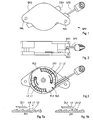
- a tensioning device SPV has a housing GHS consisting of two housing shells HS1, HS2, on which one or more chains can be fastened to suitably designed holding devices HAL, eg with pins and / or hooks (not shown).
- a tensioning cable SPS which can be used for tensioning an anti-skid chain or snow chain, is rolled up inside the tensioning device.
- a rotatably mounted in the housing rotary lever DRH protrudes as an actuator with projections through openings at opposite locations of the housing. By means of the rotary lever can be determined as needed, in which desired direction the tensioning cable is released, while at the same time a movement in the opposite direction is blocked.
- a pulley SER is provided with two concentric, mutually opposing sprockets ZK1, ZK2 located on an end face of the pulley.
- the pulley is used to wind the tension cord and is biased for this purpose with a spring FED in the winding.
- the rotary lever DRH (in Fig. 3 not shown for illustrative reasons) acts on the sprockets ZK1, ZK2 via a coaxial pawl plate KLS.
- the pawl plate is rotatably mounted by means of wing edges FL1, FL2 in corresponding recesses in the interior of the housing shell HS1, while the actuating member is pivotable about the central axis.
- Rotary lever DRH and pawl disc KLS are designed as discs with attached circular sectors, with the ends of individual circular ring sectors protrude as tabs.
- the pawl disc has elastically deformable tabs L1, L2, wherein in each case the outer tabs L1 cooperate with the outer sprocket ZK1, the inner tabs L2 with the inner sprocket ZK2.
- a cover flap DL1 of the rotary lever pushed over the outer tabs L1 and thereby pressed the latter against the sprocket ZK1, so that they engage with their teeth LZ in the sprocket.
- the pulley is blocked in one direction by inhibiting the movement because of the engaging tooth LZ, while the rotation in the other direction in the manner of a ratchet taking advantage of the elastic deformability of the tooth LZ is possible.
- the cover flap is as in Fig. 5a shown the tab L1 free, which elastically returns to its untensioned position and the sprocket ZK1 releases.
Landscapes
- Engineering & Computer Science (AREA)
- Mechanical Engineering (AREA)
- Devices For Conveying Motion By Means Of Endless Flexible Members (AREA)
- Chain Conveyers (AREA)
Description
- Die Erfindung betrifft eine Spannvorrichtung für eine Gleitschutzkette mit einem Gehäuse und einem Betätigungsglied, das zumindest zwei Blockierpositionen für einen durch eine Gehäuseöffnung in das Gehäuse einziehbaren Spannstrang aufweist, der innerhalb des Gehäuses an eine in Aufwickelrichtung vorgespannte und um ihre Achse drehbar gelagerte Wickelrolle angeschlossen ist; dabei ist in einer ersten Blockierposition des Betätigungsglieds der Spannstrang gegen Bewegung in seiner Spannrichtung blockierbar und in einer zweiten Blockierposition gegen Bewegung entgegen seiner Spannrichtung, und an der Wickelrolle ist zumindest ein Zahnkranz mit einem ihm zugeordneten Klinkenelement vorgesehen.
- Spannvorrichtungen werden bei Gleitschutzketten, insbesondere Schneeketten, verwendet, um nach der Montage ein unerwünschtes Rücklaufen des Spannstranges entgegen der Spannrichtung zu vermeiden. Der Spannstrang ist zumeist ein Spannseil, kann jedoch auch z.B. als Spannkette ausgebildet sein.
- Die
AT 408 635 B - Die
AT 006 475 U1 - Es ist Aufgabe der Erfindung, die genannten Nachteile zu überwinden und eine Spannvorrichtung mit zwei Sperrstellungen zu schaffen, bei denen jeweils die Bewegung des Spannstranges in eine Richtung (nämlich in bzw. gegen die Aufwickelrichtung) zugelassen und die andere Richtung blockiert ist.
- Diese Aufgabe wird von einer Spannvorrichtung der eingangs beschriebenen Art gelöst, bei welcher erfindungsgemäß zwei an einer Stirnfläche der Wickelrolle konzentrisch angeordnete, mit der Wickelrolle drehfest verbundene und zueinander gegenläufig orientierte Stirnzahnkränze vorgesehen sind und das Betätigungsglied als über den Zahnkränzen angeordnete Drehhebel realisiert ist, der zwischen zwei den Blockierpositionen entsprechende Endstellungen bewegbar ist, wobei zwischen Drehhebel und Zahnkränzen eine Klinkenscheibe vorgesehen ist, die drehfest im Gehäuse positioniert ist und zumindest eine äußere Lasche sowie zumindest eine innere Lasche aufweist. Die Laschen sind elastisch verbiegbar; in den Endstellungen des Drehhebels werden jeweils entweder die innere(n) Lasche(n) oder die äußeren(n) Lasche(n) gegen den entsprechenden Zahnkranz gedrückt und kommen mit diesem blockierend zum Eingriff.
- Diese Lösung erreicht das gestellte Ziel auf einfache und doch effiziente Weise. Im Gegensatz zu herkömmlichen Vorrichtungen ermöglicht die Erfindung die Verwendung eines einzelnen, zudem fest im Gehäuse angeordneten Klinkenelements, was die Bedienung sowie die Robustheit des Geräts verbessert.
- In einer bevorzugten Ausführungsform der Erfindung, die eine einfache Realisierung der Blockierwirkung in jeweils eine Drehrichtung gestattet, ist die Gestaltung der Laschen so gewählt, dass die Lasche jeweils zumindest einen gegen den zugeordneten Zahnkranz gerichteten Klinkenzahn zum Abstützen eines Zahnes des Zahnkranzes und Hemmung der entsprechenden Drehbewegung aufweist.
- Außerdem ist es günstig, wenn der Drehhebel und die Klinkenscheibe mit dem Wickelrad koaxial sind und die Laschen als an einem Grundkörper angefügte, zum Teil freistehende Kreisringsektoren gestaltet sind.
- Die Erfindung samt ihren Vorzügen und vorteilhaften Ausgestaltungen wird im Folgenden anhand eines nicht einschränkenden Ausführungsbeispiels näher erläutert, das in den beigefügten Zeichnungen dargestellt ist. Die Figuren zeigen
- Fig.1
- eine erfindungsgemäße Spannvorrichtung in Seitenansicht,
- Fig. 2
- die Spannvorrichtung in Ansicht von oben,
- Fig. 3
- eine Seitenansicht der geöffnete Spannvorrichtung mit entfernten Gehäusedeckel und Betätigungsglied,
- Fig. 4
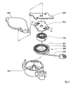
- die Spannvorrichtung in explodierter Darstellung, und
- Fig. 5a und 5b
- zwei Details zur Verdeutlichung des erfindungsgemäßen Wirkprinzips.
- Gemäß
Fig. 1 und 2 weist eine erfindungsgemäße Spannvorrichtung SPV ein Gehäuse GHS, bestehend aus zwei Gehäuseschalen HS1,HS2, auf, an dem an geeignet gestalteten Haltevorrichtungen HAL, z.B. mit (nicht gezeigten) Stiften und/oder Haken, eine oder mehrere Ketten befestigt werden können. Ein Spannseil SPS, das zum Spannen einer Gleitschutzkette oder Schneekette verwendet werden kann, ist im Inneren der Spannvorrichtung aufgerollt. Ein in dem Gehäuse verschwenkbar gelagerter Drehhebel DRH ragt als Betätigungsglied mit Fortsätzen durch Öffnungen an gegenüberliegenden Stellen des Gehäuses heraus. Mittels des Drehhebels kann je nach Bedarf festgelegt werden, in welche gewünschte Richtung das Spannseil freigegeben ist, während zugleich eine Bewegung in die entgegengesetzte Richtung blockiert ist. - Der innere Aufbau geht aus der eröffneten Ansicht
Fig. 3 (Gehäusedeckel HS2 und Drehhebel DRH sind entfernt) und der explodierten Darstellung derFig. 4 hervor. Zum Blockieren des Spannseiles SPS in eine Richtung und Freigabe in die entsprechende Gegenrichtung ist eine Seilrolle SER mit zwei an einer Stirnfläche der Seilrolle befindlichen, konzentrischen, zueinander gegenläufigen Zahnkränzen ZK1,ZK2 vorgesehen. Die Seilrolle dient zum Aufwickeln des Spannstranges und ist zu diesem Zweck mit einer Feder FED in Aufwickelrichtung vorgespannt. - Der Drehhebel DRH (in
Fig. 3 aus darstellerischen Gründen nicht gezeigt) wirkt über eine koaxiale Klinkenscheibe KLS auf die Zahnkränze ZK1,ZK2. Die Klinkenscheibe ist mittels Flügelränder FL1,FL2 in entsprechenden Ausnehmungen im Inneren der Gehäuseschale HS1 drehfest gelagert, während das Betätigungsglied um die zentrale Achse schwenkbar ist. Drehhebel DRH und Klinkenscheibe KLS sind als Scheiben mit angefügten Kreisringsektoren gestaltet, wobei die Enden einzelner Kreisringsektoren als Laschen hervorragen. Die Klinkenscheibe weist elastisch verformbare Laschen L1,L2 auf, wobei jeweils die äußeren Laschen L1 mit dem äußeren Zahnkranz ZK1, die inneren Laschen L2 mit dem inneren Zahnkranz ZK2 zusammenwirken. - Wie aus den Detailbildern der
Fig. 5a, 5b am Beispiel einer Lasche L1 erkennbar ist, weisen die Laschen L1,L2 an ihrem Ende jeweils einen dem Zahnkranz zugewandten Zahn LZ sowie eine gegenüber angeordnete Nocke LN auf. Wegen der Fixierung der Klinkenscheibe im Gehäuse ist die Lasche L1 und insbesondere der Zahn LZ entlang der Drehrichtung des Zahnkranzes unbeweglich, jedoch ist durch (elastisches) Verbiegen der Lasche eine Bewegung zum Zahnkranz hin möglich. Durch Drehung des Drehhebels DRH in eine erste Endstellung wird, wie inFig. 5b gezeigt, eine Decklasche DL1 des Drehhebels über die äußeren Laschen L1 geschoben und dadurch letztere gegen den Zahnkranz ZK1 gedrückt, sodass diese mit ihren Zähnen LZ in den Zahnkranz eingreifen. Dadurch wird die Seilrolle in eine Richtung durch Hemmung der Bewegung wegen des eingreifenden Zahnes LZ blockiert, während die Drehung in die andere Richtung nach Art einer Ratsche unter Ausnutzung der elastischen Verformbarkeit des Zahnes LZ möglich ist. Wird der Drehhebel in die andere Endstellung - im gezeigten Ausführungsbeispiel durch eine Drehung um ca. 40° - gedreht, gibt die Decklasche wie inFig. 5a gezeigt die Lasche L1 frei, die elastisch in ihre ungespannte Position zurückgeht und den Zahnkranz ZK1 freigibt. Dagegen ergibt sich nun in entsprechender Weise, freilich mit umgekehrten Umlaufsinn, das gleiche Spiel mit den inneren Laschen L2 der Klinkenscheibe; diese greifen nun in den inneren Zahnkranz ZK2 ein, und es ergibt sich eine Blockierung in die entgegengesetzte Richtung.
Claims (3)
- Spannvorrichtung (SPV) für eine Gleitschutzkette mit einem Gehäuse (HS1,HS2) und einem Betätigungsglied (DRH), das zumindest zwei Blockierpositionen für einen durch eine Gehäuseöffnung in das Gehäuse einziehbaren Spannstrang (SPS) aufweist, der innerhalb des Gehäuses an eine in Aufwickelrichtung vorgespannte und um ihre Achse drehbar gelagerte Wickelrolle (SER) angeschlossen ist, wobei in einer ersten Blockierposition des Betätigungsglieds der Spannstrang gegen Bewegung in seiner Spannrichtung blockierbar ist und in einer zweiten Blockierposition gegen Bewegung entgegen seiner Spannrichtung, wobei an der Wickelrolle zumindest ein Zahnkranz mit einem ihm zugeordneten Klinkenelement vorgesehen ist,
dadurch gekennzeichnet, dass
zwei an einer Stirnfläche der Wickelrolle konzentrisch angeordnete, mit der Wickelrolle drehfest verbundene und zueinander gegenläufig orientierte Stirnzahnkränze (ZK1,ZK2) vorgesehen sind und das Betätigungsglied als über den Zahnkränzen angeordnete Drehhebel (DRH) realisiert ist, der zwischen zwei den Blockierpositionen entsprechende Endstellungen bewegbar ist, wobei zwischen Drehhebel und Zahnkränzen eine Klinkenscheibe (KLS) vorgesehen ist, die drehfest im Gehäuse positioniert ist und zumindest eine äußere Lasche (L1) sowie zumindest eine innere Lasche (L2) aufweist, wobei die Laschen elastisch verbiegbar sind, und in den Endstellungen jeweils entweder die innere(n) Lasche(n) oder die äußeren(n) Lasche(n) durch den Drehhebel gegen den entsprechenden Zahnkranz gedrückt werden und mit diesem zum Eingriff kommen. - Spannvorrichtung nach Anspruch 1, dadurch gekennzeichnet, dass die Lasche (L1,L2) jeweils zumindest einen genen den zugeordneten Zahnkranz (ZK1,ZK2) gerichteten Klinkenzahn (LZ) zum Abstützen eines Zahnes des Zahnkranzes und Hemmung der entsprechenden Drehbewegung aufweist (Fig. 5b).
- Spannvorrichtung nach Anspruch 1 oder 2, dadurch gekennzeichnet, dass der Drehhebel und die Klinkenscheibe mit dem Wickelrad koaxial sind und die Laschen (L1,L2) als an einem Grundkörper angefügte, zum Teil freistehende Kreisringsektoren gestaltet sind.
Priority Applications (2)
| Application Number | Priority Date | Filing Date | Title |
|---|---|---|---|
| PL07450025T PL1839914T3 (pl) | 2006-03-29 | 2007-02-14 | Urządzenie napinające do łańcucha przeciwpoślizgowego |
| AT07450025T ATE434535T1 (de) | 2006-03-29 | 2007-02-14 | Spannvorrichtung für eine gleitschutzkette |
Applications Claiming Priority (1)
| Application Number | Priority Date | Filing Date | Title |
|---|---|---|---|
| AT0054106A AT502640B1 (de) | 2006-03-29 | 2006-03-29 | Spannvorrichtung für eine gleitschutzkette |
Publications (3)
| Publication Number | Publication Date |
|---|---|
| EP1839914A2 EP1839914A2 (de) | 2007-10-03 |
| EP1839914A3 EP1839914A3 (de) | 2008-05-14 |
| EP1839914B1 true EP1839914B1 (de) | 2009-06-24 |
Family
ID=38135449
Family Applications (1)
| Application Number | Title | Priority Date | Filing Date |
|---|---|---|---|
| EP07450025A Active EP1839914B1 (de) | 2006-03-29 | 2007-02-14 | Spannvorrichtung für eine Gleitschutzkette |
Country Status (4)
| Country | Link |
|---|---|
| EP (1) | EP1839914B1 (de) |
| AT (2) | AT502640B1 (de) |
| DE (1) | DE502007000914D1 (de) |
| PL (1) | PL1839914T3 (de) |
Families Citing this family (3)
| Publication number | Priority date | Publication date | Assignee | Title |
|---|---|---|---|---|
| SI1976715T1 (sl) | 2006-02-02 | 2011-01-31 | Peerless Chain Co | Samonapenjalne sneĺ˝ne verige in metode uporabe |
| EP2186660B1 (de) * | 2008-11-12 | 2011-02-09 | Peerless Chain Company | Selbstfestziehende Zugkraftanordnung mit Spannvorrichtung |
| CN106882001B (zh) * | 2017-02-23 | 2018-08-24 | 杭州萧山恒利塑料制品厂 | 一种自动收缩并锁紧的荆轮扣 |
Family Cites Families (3)
| Publication number | Priority date | Publication date | Assignee | Title |
|---|---|---|---|---|
| AT408635B (de) * | 2000-04-10 | 2002-01-25 | Pewag Austria Gmbh | Spannvorrichtung für eine schneekette |
| ITVE20040010A1 (it) * | 2004-03-30 | 2004-06-30 | Am Srl | Dispositivo di tensionamento e bloccaggio, in particolare per catene da neve. |
| DE102004037332B3 (de) * | 2004-07-28 | 2005-05-25 | Rud-Kettenfabrik Rieger & Dietz Gmbh U. Co. | Spannvorrichtung für eine Gleitschutzkette |
-
2006
- 2006-03-29 AT AT0054106A patent/AT502640B1/de not_active IP Right Cessation
-
2007
- 2007-02-14 DE DE502007000914T patent/DE502007000914D1/de active Active
- 2007-02-14 AT AT07450025T patent/ATE434535T1/de active
- 2007-02-14 PL PL07450025T patent/PL1839914T3/pl unknown
- 2007-02-14 EP EP07450025A patent/EP1839914B1/de active Active
Also Published As
| Publication number | Publication date |
|---|---|
| DE502007000914D1 (de) | 2009-08-06 |
| ATE434535T1 (de) | 2009-07-15 |
| AT502640A4 (de) | 2007-05-15 |
| EP1839914A3 (de) | 2008-05-14 |
| AT502640B1 (de) | 2007-05-15 |
| PL1839914T3 (pl) | 2009-12-31 |
| EP1839914A2 (de) | 2007-10-03 |
Similar Documents
| Publication | Publication Date | Title |
|---|---|---|
| EP0697826B1 (de) | Schuhverschluss | |
| EP2925178B1 (de) | Drehverschluss für einen schuh | |
| DE102006052167B3 (de) | Vorrichtung zum Aufrollen eines Sicherheitsgurtes | |
| DE10031472C1 (de) | Vorrichtung zur Arretierung einer von einem Rotor angetriebenen Welle einer Windkraftanlage | |
| EP1301361B1 (de) | Spannvorrichtung für eine schneekette | |
| WO1998039168A1 (de) | Spannschloss | |
| DE3203750A1 (de) | Spannschloss fuer gurtbaender | |
| DE4411015C2 (de) | Spannmechanismus mit Sicherheitsvorrichtung | |
| DE2750111A1 (de) | Vorrichtung als gleitschutz und zur erhoehung der griffigkeit von fahrzeugraedern auf eis- und schneeflaechen | |
| DE102008048134A1 (de) | Schalter für ein Fahrradgetriebe | |
| EP2151336B1 (de) | Spannschloss | |
| AT502504B1 (de) | Spannvorrichtung für eine gleitschutzkette | |
| EP1935674B1 (de) | Spannvorrichtung für eine Gleitschutzkette | |
| EP0736698B1 (de) | Spannratsche | |
| EP1839914B1 (de) | Spannvorrichtung für eine Gleitschutzkette | |
| DE202009007685U1 (de) | Spannvorrichtung für einen Gurt | |
| EP4041018B1 (de) | Drehverschluss mit spannelement | |
| DE102014108902B4 (de) | Spannschloss für eine Gleitschutzkette | |
| DE2643685C3 (de) | Aufrollvorrichtung für einen Sicherheitsgurt | |
| DE29703911U1 (de) | Spannschloß | |
| DE102016104744B4 (de) | Spannvorrichtung für eine Gleitschutzkette | |
| DE4316340C1 (de) | Schuhverschluß | |
| EP2149668B1 (de) | Endlageneinstellvorrichtung | |
| DE3203151A1 (de) | Antriebsvorrichtung fuer einen verstellmechanismus eines fahrzeugsitzes | |
| AT403886B (de) | Bindung für ein snowboard |
Legal Events
| Date | Code | Title | Description |
|---|---|---|---|
| PUAI | Public reference made under article 153(3) epc to a published international application that has entered the european phase |
Free format text: ORIGINAL CODE: 0009012 |
|
| AK | Designated contracting states |
Kind code of ref document: A2 Designated state(s): AT BE BG CH CY CZ DE DK EE ES FI FR GB GR HU IE IS IT LI LT LU LV MC NL PL PT RO SE SI SK TR |
|
| AX | Request for extension of the european patent |
Extension state: AL BA HR MK YU |
|
| PUAL | Search report despatched |
Free format text: ORIGINAL CODE: 0009013 |
|
| AK | Designated contracting states |
Kind code of ref document: A3 Designated state(s): AT BE BG CH CY CZ DE DK EE ES FI FR GB GR HU IE IS IT LI LT LU LV MC NL PL PT RO SE SI SK TR |
|
| AX | Request for extension of the european patent |
Extension state: AL BA HR MK RS |
|
| 17P | Request for examination filed |
Effective date: 20081103 |
|
| GRAP | Despatch of communication of intention to grant a patent |
Free format text: ORIGINAL CODE: EPIDOSNIGR1 |
|
| AKX | Designation fees paid |
Designated state(s): AT BE BG CH CY CZ DE DK EE ES FI FR GB GR HU IE IS IT LI LT LU LV MC NL PL PT RO SE SI SK TR |
|
| GRAS | Grant fee paid |
Free format text: ORIGINAL CODE: EPIDOSNIGR3 |
|
| GRAA | (expected) grant |
Free format text: ORIGINAL CODE: 0009210 |
|
| AK | Designated contracting states |
Kind code of ref document: B1 Designated state(s): AT BE BG CH CY CZ DE DK EE ES FI FR GB GR HU IE IS IT LI LT LU LV MC NL PL PT RO SE SI SK TR |
|
| REG | Reference to a national code |
Ref country code: GB Ref legal event code: FG4D Free format text: NOT ENGLISH |
|
| REG | Reference to a national code |
Ref country code: CH Ref legal event code: EP |
|
| REG | Reference to a national code |
Ref country code: IE Ref legal event code: FG4D Free format text: LANGUAGE OF EP DOCUMENT: GERMAN |
|
| REF | Corresponds to: |
Ref document number: 502007000914 Country of ref document: DE Date of ref document: 20090806 Kind code of ref document: P |
|
| PG25 | Lapsed in a contracting state [announced via postgrant information from national office to epo] |
Ref country code: FI Free format text: LAPSE BECAUSE OF FAILURE TO SUBMIT A TRANSLATION OF THE DESCRIPTION OR TO PAY THE FEE WITHIN THE PRESCRIBED TIME-LIMIT Effective date: 20090624 Ref country code: LT Free format text: LAPSE BECAUSE OF FAILURE TO SUBMIT A TRANSLATION OF THE DESCRIPTION OR TO PAY THE FEE WITHIN THE PRESCRIBED TIME-LIMIT Effective date: 20090624 |
|
| PG25 | Lapsed in a contracting state [announced via postgrant information from national office to epo] |
Ref country code: SI Free format text: LAPSE BECAUSE OF FAILURE TO SUBMIT A TRANSLATION OF THE DESCRIPTION OR TO PAY THE FEE WITHIN THE PRESCRIBED TIME-LIMIT Effective date: 20090624 Ref country code: SE Free format text: LAPSE BECAUSE OF FAILURE TO SUBMIT A TRANSLATION OF THE DESCRIPTION OR TO PAY THE FEE WITHIN THE PRESCRIBED TIME-LIMIT Effective date: 20090924 Ref country code: LV Free format text: LAPSE BECAUSE OF FAILURE TO SUBMIT A TRANSLATION OF THE DESCRIPTION OR TO PAY THE FEE WITHIN THE PRESCRIBED TIME-LIMIT Effective date: 20090624 |
|
| REG | Reference to a national code |
Ref country code: PL Ref legal event code: T3 |
|
| PG25 | Lapsed in a contracting state [announced via postgrant information from national office to epo] |
Ref country code: IS Free format text: LAPSE BECAUSE OF FAILURE TO SUBMIT A TRANSLATION OF THE DESCRIPTION OR TO PAY THE FEE WITHIN THE PRESCRIBED TIME-LIMIT Effective date: 20091024 Ref country code: ES Free format text: LAPSE BECAUSE OF FAILURE TO SUBMIT A TRANSLATION OF THE DESCRIPTION OR TO PAY THE FEE WITHIN THE PRESCRIBED TIME-LIMIT Effective date: 20091005 Ref country code: EE Free format text: LAPSE BECAUSE OF FAILURE TO SUBMIT A TRANSLATION OF THE DESCRIPTION OR TO PAY THE FEE WITHIN THE PRESCRIBED TIME-LIMIT Effective date: 20090624 |
|
| REG | Reference to a national code |
Ref country code: IE Ref legal event code: FD4D |
|
| PG25 | Lapsed in a contracting state [announced via postgrant information from national office to epo] |
Ref country code: SK Free format text: LAPSE BECAUSE OF FAILURE TO SUBMIT A TRANSLATION OF THE DESCRIPTION OR TO PAY THE FEE WITHIN THE PRESCRIBED TIME-LIMIT Effective date: 20090624 |
|
| PG25 | Lapsed in a contracting state [announced via postgrant information from national office to epo] |
Ref country code: PT Free format text: LAPSE BECAUSE OF FAILURE TO SUBMIT A TRANSLATION OF THE DESCRIPTION OR TO PAY THE FEE WITHIN THE PRESCRIBED TIME-LIMIT Effective date: 20091024 Ref country code: BG Free format text: LAPSE BECAUSE OF FAILURE TO SUBMIT A TRANSLATION OF THE DESCRIPTION OR TO PAY THE FEE WITHIN THE PRESCRIBED TIME-LIMIT Effective date: 20090924 |
|
| PG25 | Lapsed in a contracting state [announced via postgrant information from national office to epo] |
Ref country code: DK Free format text: LAPSE BECAUSE OF FAILURE TO SUBMIT A TRANSLATION OF THE DESCRIPTION OR TO PAY THE FEE WITHIN THE PRESCRIBED TIME-LIMIT Effective date: 20090624 Ref country code: IE Free format text: LAPSE BECAUSE OF FAILURE TO SUBMIT A TRANSLATION OF THE DESCRIPTION OR TO PAY THE FEE WITHIN THE PRESCRIBED TIME-LIMIT Effective date: 20090624 |
|
| PLBE | No opposition filed within time limit |
Free format text: ORIGINAL CODE: 0009261 |
|
| STAA | Information on the status of an ep patent application or granted ep patent |
Free format text: STATUS: NO OPPOSITION FILED WITHIN TIME LIMIT |
|
| 26N | No opposition filed |
Effective date: 20100325 |
|
| BERE | Be: lapsed |
Owner name: PEWAG SCHNEEKETTEN GMBH & CO KG Effective date: 20100228 |
|
| PG25 | Lapsed in a contracting state [announced via postgrant information from national office to epo] |
Ref country code: GR Free format text: LAPSE BECAUSE OF FAILURE TO SUBMIT A TRANSLATION OF THE DESCRIPTION OR TO PAY THE FEE WITHIN THE PRESCRIBED TIME-LIMIT Effective date: 20090925 Ref country code: MC Free format text: LAPSE BECAUSE OF NON-PAYMENT OF DUE FEES Effective date: 20100301 |
|
| PG25 | Lapsed in a contracting state [announced via postgrant information from national office to epo] |
Ref country code: BE Free format text: LAPSE BECAUSE OF NON-PAYMENT OF DUE FEES Effective date: 20100228 |
|
| PGFP | Annual fee paid to national office [announced via postgrant information from national office to epo] |
Ref country code: PL Payment date: 20110128 Year of fee payment: 5 Ref country code: CZ Payment date: 20110210 Year of fee payment: 5 |
|
| PGRI | Patent reinstated in contracting state [announced from national office to epo] |
Ref country code: IT Effective date: 20110501 |
|
| PGRI | Patent reinstated in contracting state [announced from national office to epo] |
Ref country code: IT Effective date: 20110501 |
|
| GBPC | Gb: european patent ceased through non-payment of renewal fee |
Effective date: 20110214 |
|
| PG25 | Lapsed in a contracting state [announced via postgrant information from national office to epo] |
Ref country code: GB Free format text: LAPSE BECAUSE OF NON-PAYMENT OF DUE FEES Effective date: 20110214 |
|
| PGFP | Annual fee paid to national office [announced via postgrant information from national office to epo] |
Ref country code: NL Payment date: 20120228 Year of fee payment: 6 |
|
| PG25 | Lapsed in a contracting state [announced via postgrant information from national office to epo] |
Ref country code: CY Free format text: LAPSE BECAUSE OF FAILURE TO SUBMIT A TRANSLATION OF THE DESCRIPTION OR TO PAY THE FEE WITHIN THE PRESCRIBED TIME-LIMIT Effective date: 20090624 |
|
| PG25 | Lapsed in a contracting state [announced via postgrant information from national office to epo] |
Ref country code: HU Free format text: LAPSE BECAUSE OF FAILURE TO SUBMIT A TRANSLATION OF THE DESCRIPTION OR TO PAY THE FEE WITHIN THE PRESCRIBED TIME-LIMIT Effective date: 20091225 Ref country code: LU Free format text: LAPSE BECAUSE OF NON-PAYMENT OF DUE FEES Effective date: 20100214 |
|
| REG | Reference to a national code |
Ref country code: NL Ref legal event code: T3 |
|
| PG25 | Lapsed in a contracting state [announced via postgrant information from national office to epo] |
Ref country code: CZ Free format text: LAPSE BECAUSE OF NON-PAYMENT OF DUE FEES Effective date: 20120214 Ref country code: TR Free format text: LAPSE BECAUSE OF FAILURE TO SUBMIT A TRANSLATION OF THE DESCRIPTION OR TO PAY THE FEE WITHIN THE PRESCRIBED TIME-LIMIT Effective date: 20090624 |
|
| REG | Reference to a national code |
Ref country code: NL Ref legal event code: V1 Effective date: 20130901 |
|
| PG25 | Lapsed in a contracting state [announced via postgrant information from national office to epo] |
Ref country code: NL Free format text: LAPSE BECAUSE OF NON-PAYMENT OF DUE FEES Effective date: 20130901 |
|
| PGFP | Annual fee paid to national office [announced via postgrant information from national office to epo] |
Ref country code: CH Payment date: 20140218 Year of fee payment: 8 |
|
| PG25 | Lapsed in a contracting state [announced via postgrant information from national office to epo] |
Ref country code: PL Free format text: LAPSE BECAUSE OF NON-PAYMENT OF DUE FEES Effective date: 20130214 |
|
| REG | Reference to a national code |
Ref country code: PL Ref legal event code: LAPE |
|
| PG25 | Lapsed in a contracting state [announced via postgrant information from national office to epo] |
Ref country code: RO Free format text: LAPSE BECAUSE OF FAILURE TO SUBMIT A TRANSLATION OF THE DESCRIPTION OR TO PAY THE FEE WITHIN THE PRESCRIBED TIME-LIMIT Effective date: 20090624 |
|
| REG | Reference to a national code |
Ref country code: CH Ref legal event code: PL |
|
| PG25 | Lapsed in a contracting state [announced via postgrant information from national office to epo] |
Ref country code: CH Free format text: LAPSE BECAUSE OF NON-PAYMENT OF DUE FEES Effective date: 20150228 Ref country code: LI Free format text: LAPSE BECAUSE OF NON-PAYMENT OF DUE FEES Effective date: 20150228 |
|
| REG | Reference to a national code |
Ref country code: FR Ref legal event code: PLFP Year of fee payment: 10 |
|
| REG | Reference to a national code |
Ref country code: FR Ref legal event code: PLFP Year of fee payment: 11 |
|
| REG | Reference to a national code |
Ref country code: FR Ref legal event code: PLFP Year of fee payment: 12 |
|
| PGFP | Annual fee paid to national office [announced via postgrant information from national office to epo] |
Ref country code: AT Payment date: 20240220 Year of fee payment: 18 |
|
| PGFP | Annual fee paid to national office [announced via postgrant information from national office to epo] |
Ref country code: DE Payment date: 20240219 Year of fee payment: 18 |
|
| PGFP | Annual fee paid to national office [announced via postgrant information from national office to epo] |
Ref country code: IT Payment date: 20240228 Year of fee payment: 18 Ref country code: FR Payment date: 20240220 Year of fee payment: 18 |