EP1839234B1 - Systeme de surveillance de transport - Google Patents
Systeme de surveillance de transport Download PDFInfo
- Publication number
- EP1839234B1 EP1839234B1 EP05801444A EP05801444A EP1839234B1 EP 1839234 B1 EP1839234 B1 EP 1839234B1 EP 05801444 A EP05801444 A EP 05801444A EP 05801444 A EP05801444 A EP 05801444A EP 1839234 B1 EP1839234 B1 EP 1839234B1
- Authority
- EP
- European Patent Office
- Prior art keywords
- transport
- unit
- monitoring system
- transport monitoring
- goods
- Prior art date
- Legal status (The legal status is an assumption and is not a legal conclusion. Google has not performed a legal analysis and makes no representation as to the accuracy of the status listed.)
- Not-in-force
Links
Images


Classifications
-
- G—PHYSICS
- G06—COMPUTING; CALCULATING OR COUNTING
- G06K—GRAPHICAL DATA READING; PRESENTATION OF DATA; RECORD CARRIERS; HANDLING RECORD CARRIERS
- G06K19/00—Record carriers for use with machines and with at least a part designed to carry digital markings
- G06K19/06—Record carriers for use with machines and with at least a part designed to carry digital markings characterised by the kind of the digital marking, e.g. shape, nature, code
- G06K19/067—Record carriers with conductive marks, printed circuits or semiconductor circuit elements, e.g. credit or identity cards also with resonating or responding marks without active components
- G06K19/07—Record carriers with conductive marks, printed circuits or semiconductor circuit elements, e.g. credit or identity cards also with resonating or responding marks without active components with integrated circuit chips
- G06K19/0723—Record carriers with conductive marks, printed circuits or semiconductor circuit elements, e.g. credit or identity cards also with resonating or responding marks without active components with integrated circuit chips the record carrier comprising an arrangement for non-contact communication, e.g. wireless communication circuits on transponder cards, non-contact smart cards or RFIDs
-
- G—PHYSICS
- G06—COMPUTING; CALCULATING OR COUNTING
- G06K—GRAPHICAL DATA READING; PRESENTATION OF DATA; RECORD CARRIERS; HANDLING RECORD CARRIERS
- G06K17/00—Methods or arrangements for effecting co-operative working between equipments covered by two or more of main groups G06K1/00 - G06K15/00, e.g. automatic card files incorporating conveying and reading operations
-
- G—PHYSICS
- G06—COMPUTING; CALCULATING OR COUNTING
- G06K—GRAPHICAL DATA READING; PRESENTATION OF DATA; RECORD CARRIERS; HANDLING RECORD CARRIERS
- G06K19/00—Record carriers for use with machines and with at least a part designed to carry digital markings
- G06K19/06—Record carriers for use with machines and with at least a part designed to carry digital markings characterised by the kind of the digital marking, e.g. shape, nature, code
- G06K19/067—Record carriers with conductive marks, printed circuits or semiconductor circuit elements, e.g. credit or identity cards also with resonating or responding marks without active components
- G06K19/07—Record carriers with conductive marks, printed circuits or semiconductor circuit elements, e.g. credit or identity cards also with resonating or responding marks without active components with integrated circuit chips
- G06K19/077—Constructional details, e.g. mounting of circuits in the carrier
- G06K19/07749—Constructional details, e.g. mounting of circuits in the carrier the record carrier being capable of non-contact communication, e.g. constructional details of the antenna of a non-contact smart card
- G06K19/07758—Constructional details, e.g. mounting of circuits in the carrier the record carrier being capable of non-contact communication, e.g. constructional details of the antenna of a non-contact smart card arrangements for adhering the record carrier to further objects or living beings, functioning as an identification tag
-
- G—PHYSICS
- G06—COMPUTING; CALCULATING OR COUNTING
- G06Q—INFORMATION AND COMMUNICATION TECHNOLOGY [ICT] SPECIALLY ADAPTED FOR ADMINISTRATIVE, COMMERCIAL, FINANCIAL, MANAGERIAL OR SUPERVISORY PURPOSES; SYSTEMS OR METHODS SPECIALLY ADAPTED FOR ADMINISTRATIVE, COMMERCIAL, FINANCIAL, MANAGERIAL OR SUPERVISORY PURPOSES, NOT OTHERWISE PROVIDED FOR
- G06Q10/00—Administration; Management
- G06Q10/08—Logistics, e.g. warehousing, loading or distribution; Inventory or stock management
- G06Q10/087—Inventory or stock management, e.g. order filling, procurement or balancing against orders
Definitions
- the invention relates to a transport monitoring system for tap-proof transport of goods.
- the US 2004 / 0069,850 A1 describes a transport device with a closable transport unit, wherein the closing of the transport unit is sensed by a door sensor.
- the goods transported in the transport device have RFID tags, which are read out by means of a transceiver. Each time the door is closed, the inventory within the transport device is evaluated.
- the CA 2411 395 A1 describes a system for automatically enforcing regulatory compliance for a vehicle.
- an operating parameter of the vehicle is detected by a sensor, in particular a speed sensor, and an alarm is triggered when the operating parameter exceeds a certain threshold.
- the WO 03/023439 A2 describes a shipping container with an integrated localization unit.
- the second FIG. 1 shows a transport monitoring system in the prior art.
- FIG. 1 shows a transport monitoring system according to the prior art. In it are transported from a warehouse A goods in a warehouse B. For transport monitoring, the goods W are provided with so-called tags T.
- Tags are identification components that are made a carrier, for example, consist of a product label and a small-sized transponder chip.
- RFID radio frequency identification
- the tags are used to identify the goods provided with them.
- a reading unit or reader has a receiving unit for transmitting and receiving electromagnetic waves. The radiated waves are picked up by a coil provided in the tags.
- Tags receive from the transceiver of the reader a signal pulse for returning an individual response signal to the reader.
- Passive tags do not have their own power supply, but pick up the power of the transmit pulse radiated by the reader, using the recorded power to generate the response signal. Passive tags naturally have a relatively short range.
- Semi-active tags have their own power supply, whereby part of the power required for the response is supplied by the own power supply and another part is obtained from the power of the signal received by the reader.
- the range of semi-active tags is slightly higher than that of passive tags.
- Active tags also have their own power supply, with the power for the product identification response signal being obtained entirely from its own power supply.
- the goods to be transported W are loaded by a reading unit LA from the warehouse A in a transport device, for example in a truck.
- the reading unit LA detects the goods loaded in the truck by means of the tags T attached to the goods W.
- An evaluation unit is connected to the reading unit LA which, for example, updates the stock inventory list of the warehouse A.
- the transport device or the truck brings the goods provided with tags T to a destination warehouse B.
- the goods are unloaded from the truck, passed through a reading unit B and stored in the destination B.
- the reading unit B detects the goods W brought into the warehouse B by means of the tags T attached to the goods W.
- An evaluation unit connected to the reading unit LB updates the inventory of the warehouse B.
- FIG. 1 shown transport monitoring system has some disadvantages. There is a risk that goods are indeed passed through the reading unit LA, but not actually get into the truck or in the transport device. Goods may intentionally or unintentionally pass through the reading unit LA without being invited into the truck. For example, goods W are mistakenly loaded into a wrong truck going to another warehouse. In addition, there is no control over the goods while they are in the transport device on the transport route between the two camps A, B.
- the in the DE 19 844 631 A1 described transport device such as a truck, includes a read / write device for reading tags T, which are attached to goods W within the transport device.
- the reading unit or the reader sends interrogation signals, ⁇ . H. electromagnetic signals, in the transport space of the truck and receives identification data signals from the transponders located in the transport space.
- An evaluation unit attached to the reading unit or to the reader evaluates the received identification data signals. As a result, it is monitored, for example, whether there are still all invited goods in the transport room.
- the attached to the goods mobile disk or tags send to the reading unit identification data and object-specific data.
- the tags attached to the merchandise send other data, such as data indicating the temperature in the shipping container. If, for example, the measured temperature exceeds or falls below a threshold value, this triggers a warning avoidance for the driver of the truck, which initiates the necessary countermeasures.
- the reading unit must emit a query signal permanently or at regular intervals (for example, every 5 minutes) in the transport space of the truck. If it is suspected that goods have been stolen from the transport space, the read / write device can also be activated by the driver to read the tags.
- a disadvantage of in the DE 19 844 631 A1 described transport monitoring system is that in a periodically or permanently transmitted interrogation signal, the use of active tags for monitoring the goods is uncertain. By periodically sending out the interrogation signal, the power supply or battery of the active tags is regularly consumed, so that the battery of the active tags empties over time.
- the batteries of the tags After the batteries of the tags are empty, they can not send back an identification data signal to the reader, which leads to unwanted false messages. If the time intervals between the interrogation signals are increased, for example to a time period of 10 minutes, there is a risk that goods will be stolen from the transport device in the meantime. Although increasing the time period when sending the interrogation signal prolongs the shelf life of the active tags, the loss or theft of goods is usually discovered later.
- FIG. 2 illustrated conventional transport monitoring system Another disadvantage of in FIG. 2 illustrated conventional transport monitoring system is that the system is not tap-proof. If interrogation signals are sent by write / read units into the transport device, they reply to the Tagged tags by returning identification data signals to the reader unit. Since the identification data signals also radiate outside the transport device, for example, to a behind-the-truck vehicle, it is possible for third parties to easily determine from the radiated identification data signals which goods are being transported in the truck.
- Third parties can thus determine whether a theft of the goods is worthwhile. Thus, due to the lack of security against eavesdropping, it can not be guaranteed that the secret transport of certain goods, for example in the military sector, is noticed by third parties.
- FIG. 2 Another disadvantage of in FIG. 2
- the prior art transport apparatus shown is that the interrogation signal sent by the read / write unit and the identification data signals sent back from the tags lead to problems in electromagnetic compatibility. Interrogation signals and the returned identification data signals may interfere with other electronic systems in the transport device. If, for example, the transport device is an aircraft, the intermittently transmitted interrogation signal and the returned identification data signals can disturb the sensitive electronics present there and present a security risk.
- FIG. 2 Another disadvantage of in FIG. 2
- the transport device according to the prior art shown is that it is a local transport monitoring system, in which the driver of the transport device responds to error messages. For example, if goods are stolen with the help of the driver from the transport device, this can not be determined immediately.
- the closure sensor attached to the closing device If, during the loading of the transport unit, it is closed against burglary by a closing device, the closure sensor attached to the closing device generates the activation signal for activating the reading unit. This then sends once a query signal for reading the identification tag in the transport space or in the transport unit and then receives once or a few times the returned from the identification tags identification data signals, which are evaluated in the evaluation.
- the reading unit will not emit any further interrogation signal into the transport unit for reading the identification tags unless it receives another activation signal. This ensures that unauthorized third parties do not receive identification data signals from the transport unit when the transport device is on the transport route. As long as the locking device is firmly closed, a stealing of the goods is excluded from the transport unit, so that does not have to be ensured by periodically sending an interrogation signal that the goods are still within the transport unit. Of course, if desired by the reading unit, an interrogation signal can be sent to the transport unit if the driver actively initiates this or if a central unit sends a corresponding activation signal to the transport device.
- the transport monitoring system is also suitable for goods that are provided with active tags. Due to the rarely received interrogation signals, the battery of the tags attached to the goods is much longer lasting. Active tags have the advantage of a higher range within the transport space. The volume of the transport unit to which the goods are invited may therefore be considerably larger than that in FIG. 2 illustrated transport device According to the state of the art.
- the latter has a transmitting / receiving antenna for emitting the interrogation signal into the transport unit and for receiving the identification data signals from the identification tags
- transmitting / receiving antennas can be provided within the transport unit, which are connected to the reading unit.
- the evaluation unit has at least one interface for wireless data transmission.
- an activation signal for activating the reading unit is transmitted via this interface to the evaluation unit from a remote central unit.
- the central unit sends a message to activate the reading unit while the transport device is on the transport route and receives a message which comprises the identification data signals of the marked goods.
- the central unit can thus determine the type and amount of goods transported in the transport device during transport.
- the transport monitoring system contains as the second activation unit a speed sensor for detecting the travel speed of the transport device, wherein the activation signal for activating the reading unit is not generated until the travel speed of the transport device has exceeded an adjustable speed threshold.
- the transport monitoring system as a further activation unit on a loading sensor for detecting a loading weight of the transport device, wherein the Activation signal is generated only when the load weight has exceeded an adjustable weight threshold.
- the transport unit is preferably a container.
- the identification tags are active tags with their own power supply.
- the identification tags are passive tags without their own power supply.
- the identification tags attached to the goods are each provided with RFID transponders.
- These RFID transponders are preferably attached to a product label.
- these state sensors for detecting the transport state of the goods, wherein the state sensors are connected to the evaluation unit.
- condition sensors preferably include temperature sensors for detecting the temperature within the transport unit.
- the state sensors preferably comprise speed sensors for detecting a traveling speed of the transport device.
- the state sensors preferably further comprise acceleration sensors for detecting the acceleration of the transport device.
- the transport monitoring system comprises a transport unit, in particular a motor vehicle, for example a truck.
- the motor vehicle state sensors are preferably provided, which are connected to the evaluation unit for detecting the transport state of the goods transported in the motor vehicle.
- the condition sensors include tire pressure sensors for detecting the tire pressure of tires of the motor vehicle.
- the evaluation unit of the transport monitoring system preferably comprises an interface to the reading unit and a processor for data processing of the identification data signals received by the reading unit.
- the evaluation unit also has an interface for connecting state sensors and an interface for connecting an activation unit.
- the evaluation unit of the transport monitoring system according to the invention further comprises a GSM unit for exchanging messages with a central unit.
- the evaluation unit additionally contains a GPS unit for detecting the position of the transport device.
- the invention further provides a transport monitoring system for monitoring a goods flow consisting of goods having a plurality of transport devices and having at least one central unit which exchanges messages with the transport devices via an interface.
- Transport device 1 for transporting goods in the illustrated embodiment, a transport unit 2 for receiving goods 3, which are each provided with identification tags 4.
- Transport device 1 shown is a truck.
- the transport unit 2 consists of the load compartment of the truck. In further embodiments, it is at the transport unit 2 to a freight car of a train or to a motor vehicle trailer.
- the transport unit 2 in alternative embodiments may also be a transport container within a ship or within an aircraft.
- the transport unit 2 preferably closed by a door 5.
- a closure sensor 6 attached to a closing device detects whether the transport unit 2 is closed.
- the transport device 1 contains an integrated telematics unit 7.
- the telematics unit 7 is preferably also firmly integrated in the transport unit 2.
- the telematics unit 7 preferably has a fixed housing, which protects the telematics unit 7 from manipulation.
- the telematics unit 7 contains a reading unit 8, an evaluation unit 9 and a radio interface 10.
- the reading unit 8 and the radio interface 10 are not integrated into the telematics unit 7.
- At least one transmitting / receiving antenna 11, which is located within the transport unit 2, is connected to the reading unit 8.
- the transmission / reception antenna 11 is suitable for emitting an interrogation signal into the transport unit 2 and for receiving identification data signals emitted by identification tags 4 within the transport unit 2.
- the closure sensor 6 is connected via a line 12 to the evaluation unit 9.
- the conduit 12 is laid tamper evident within the transport device 1.
- a status sensor 13 is preferably connected to the evaluation unit 9 via a line 14.
- the state sensor 13 is also located within the transport unit 2.
- the state sensors 13 serve to detect the transport state of the goods transported within the transport unit 2.
- the transport unit 2 is loaded at the loading location.
- the transport unit 2 is opened by means of the door 5, and the shutter sensor 6 indicates to the telematics 7 that the transport unit 2 is now open.
- the goods 3 provided with identification tags 4 are loaded into the transport unit 2, and then the door 5 is locked.
- the closure sensor 6 As soon as the closure sensor 6 detects that the door 5 is firmly locked, it sends an activation signal via the line 12 to the evaluation unit 9 or directly to the reading unit 8 to the latter Activation off.
- the reading unit 8 is connected via lines 15 to the evaluation unit 9.
- the evaluation unit 9 activates the reading unit 8 so that it emits an interrogation signal for reading out the identification tags 4 in the transport space enclosed by the transport unit 2.
- the tags 4, which receive the interrogation signal send identification data signals back to the transmitting and receiving antenna 11 of the reading unit 8, which emits the received identification data signals for evaluation thereof to the evaluation unit 9 via the line 15.
- the interrogation signal for reading the tags 4 is sent out only after the transport unit 2 is firmly closed, ie after the inventory within the transport unit 2 no longer changes.
- the reading unit 8 of the transport device 1 according to the invention must emit an interrogation signal only once.
- no further interrogation signal is radiated into the transport space by the reading unit 8, provided that the reading unit 8 does not receive any further activation signal.
- the evaluation unit 9 is connected via a line 16 to a radio interface 10.
- the radio interface 10 is an interface for wireless data transmission with a remote central unit.
- the central unit transmits, if necessary, messages to the transport device 1 according to the invention, wherein the messages may contain an activation signal for activating the reading unit 8. In this way, if necessary, the inventory within the transport unit 2 can be determined.
- the evaluation unit 9 evaluates the received identification data signals and sends, for example, an inventory list, which indicates the current stock loaded in the transport device 1, via the radio interface 10 to a remote central unit. If the central unit sends no further activation signal during transport, no further interrogation signal is emitted by the reading unit 8 into the transport space.
- the transport device 1 While the transport device 1 is on the transport route, it is thus not possible for third parties to listen to further identification data signals so that unauthorized third parties can not determine which goods are in the transport device 1.
- the transport unit 2 If the transport unit 2 is located, for example, inside an aircraft, it can be ensured during the transport in the air that no interrogation signals are emitted in the transport space of the aircraft. This prevents the identification data signals from being emitted during transport in the air and disturbing other electronic systems of the aircraft.
- the evaluation unit 9 can receive activation signals from further sensors. At the in FIG. 3 illustrated embodiment, for example, a speed sensor is additionally provided, which serves to detect the driving speed of the transport device 1. In this case, the read-out of the tags 4 is triggered only after the transport device 1 exceeds an adjustable speed threshold. For example, the inventory within the transport unit 2 is only determined when the truck exceeds the speed of 10 km / h on its departure.
- loading sensors for detecting a loading weight of the transport device 1 are additionally provided, for example.
- the loading sensor generates an activation signal when the loading weight of the transport device 1 exceeds an adjustable weight threshold.
- the interrogation signal is not automatically emitted as required at certain time intervals from the reading unit 8 by means of the transmitting / receiving antenna 11 in the transport space of the transport unit 2.
- the activation signals generated by the various activation units can be logically linked within the evaluation unit 9 by means of a logic device, not shown. For example, an interrogation signal is generated only after the door 5 is tightly closed and the approach speed is more than 10 km / h.
- the identification tags 4 attached to the goods 3 are either active tags with their own power supply or passive tags that do not have their own power supply.
- the identification tags 4 preferably have an RFID transponder, which is preferably attached to a product label.
- the evaluation unit 9 is preferably connected to at least one condition sensor 13.
- 2 temperature sensors for detecting the internal temperature within the transport unit 2 are provided in the transport unit. If, for example, the product 3 is perishable food, it can be determined by means of the temperature sensors 3 whether the desired cool room temperature of the transport unit 2 is present. As soon as the temperature exceeds a certain threshold value and this is detected by the evaluation unit 9, the evaluation unit 9 sends an alarm signal via the radio interface 10 to the central unit and optionally a warning signal to the driver of the transport device 1.
- a state sensor 17 is connected via a line 18 to the evaluation unit 9.
- the state sensor 17 may be, for example, a speed sensor for detecting the travel speed of the transport device 1.
- the state sensor 17 may be an acceleration sensor for detecting the acceleration of the transport device 1.
- the transport device 1 is any transport device, such as a vehicle, a train, an aircraft or a ship.
- the sensor 17 is, for example, a tire pressure sensor for detecting the tire pressure of the tires of the motor vehicle 1.
- FIG. 4 shows a block diagram of a particularly preferred embodiment of the telematics unit 7 within the transport device 1.
- the telematics unit 7 contains a processor 19 for data processing of the identification data signals received by the reading unit 8.
- the reading unit 8 is connected to the processor 19 via an interface 20 of the telematics unit 7.
- the telematics unit 7 preferably has a memory 21 for storing data.
- the activation unit 6, which is formed for example by a closure sensor, is connected via a further interface 22 to the processor 19 of the telematics unit 7.
- the state sensors 13, 17 are connected via further interfaces 23 of the telematics unit 7 the processor 19 connected.
- a GPS module 24 and a GSM module 25 are also connected.
- the GPS module 24 receives via an antenna 26 position data indicating the position of the transport device 1.
- the processor 19 preferably exchanges message packets with a remote central unit via the GSM module 25 and the transmitting / receiving antenna 27 connected thereto.
- the GSM module 25 forms, together with the transmitting / receiving antenna 27, a wireless radio interface 10 as shown in FIG FIG. 3 is shown.
- the telematics unit 7 is powered by its own power supply or battery, for example by the vehicle battery of the truck 1, with voltage.
- the telematics unit 7 is preferably integrated in a housing 28 which protects the telematics unit 7 from manipulation.
- FIG. 5 schematically shows the interconnection of the telematics unit 7 according to the invention within a truck. 1
- the processor 19 From satellite receives the processor 19 by means of the connected GPS module 24, the position data or the coordinates of the transport device 1. About the GSM module 25, the processor 19 receives messages or commands from a remote central unit 34. Conversely, the processor 19 send messages or messages to the remote central unit 34 via the GSM module 25. A closure sensor 6 indicates to the processor 19 whether the door 5 of the transport unit 2 is tightly closed.
- a temperature sensor 13 provided within the transport unit 2 sends to the processor 19 data indicating the temperature within the transport space.
- the processor 19 is connected to a reading unit 8 via a serial interface RS232 and receives a voltage of, for example, 12 volts via a voltage supply line 29 via an independent power supply.
- sensors for example load sensors 30 and a shock sensor 31 are connected to the telematics unit 7.
- the telematics unit 7 is further fed by a battery 32 of the transport device 1, wherein a sensor 33 monitors the state of charge of the battery 32. As a result, it can be established at an early stage whether the state of charge of the battery 32 for supplying power to the telematics unit 7 becomes critical.
- the corresponding alarm message can be sent by the telematics unit 7 to the remote central unit 34.
- a unexpected event occurs, such as the unplanned opening of the transport unit 2, exceeding or falling below a predetermined temperature, a critical state of charge of the battery 32, a heavy impact of the transport device 1, in particular as a result of an accident or the like, causes the telematics unit 7 via the GSM module 25 sends an alarm message to the remote central unit 34.
- This can then cause the corresponding countermeasures, or instruct the driver of the transport device 1 accordingly.
- the goods recipients at the destination can be informed early about the delayed arrival of the goods.
- the data exchange between the telematics unit 7 and the remote central unit 34 can take place, for example, via GSM, W-LAN, Bluetooth, LAN or SAT-COM or other suitable transmission protocols.
- FIG. 6 shows a diagram for explaining the operation of the transport monitoring system according to the invention.
- goods can be transported by means of a transport device 1 from a place of departure to a destination.
- the transport device 1 at the departure which is located at a predefined waypoint 0 of a transport plan, loaded.
- the control center 34 sends the transport plan to the telematics unit 7 of the transport device 1 via a wireless data connection, for example via the GSM interface.
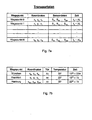
- FIGS. 7a, 7b show examples of such a transport plan.
- the goods 3 are loaded into the transport unit 2 of the transport device 1, and after the transport device 2 is closed, the reading unit 8 sends the interrogation signal into the transport space.
- the goods 3 loaded into the transport unit 2 are identified by means of the identification data signals, and the telematics unit 7 sends, for example, an inventory list to the remote central unit 34. For example, once the transport device 1 has started to move, a departure message is sent to the center 34.
- the telematics unit 7 receives at the beginning of the transport process a fixed transport plan from the center 34.
- Per waypoint a complete sensor configuration in the form of sensor data is given.
- a time window is optionally determined as a tolerance range.
- the sensor data S indicate the desired state at the respective waypoint.
- FIG. 7b shows a simple example of a transportation plan.
- the cargo is to be transported from Kunststoff via Frankfurt to Hamburg, whereby the door should remain closed over the entire journey.
- the room temperature within the transport unit 2 should be lowered after loading for cooling the goods and be at most Frankfurt at 25 ° C.
- the transport starting from Kunststoff should start at 14 o'clock + - 30 minutes.
- the transport device 1 should reach 22 hours + -1 hour according to the transport plan Hamburg. If the sensor data at the respective waypoint deviates from the desired sensor target data, an alarm signal is generated by the telematics unit 7 according to the invention and transmitted to the central unit 34. For example, if it is determined at the waypoint Frankfurt that the temperature is more than 25 ° C within the transport unit 2, a corresponding alarm signal is sent to the control center.
- a warning signal is also sent to the control panel.
- a timestamp is generated by the telematics unit 7, and a warning signal is sent to the center if the timestamps are not within the time-tolerance range.
- priorities may be assigned to the various messages. For example, opening the door may result in a high priority alarm signal, while a slight overshoot of the temperature threshold may result in a low priority message.
- the transport device 1 moves first to the waypoint A of the transport plan.
- watchboxes defined by a geographical point with a radius. Entry or exit from such a geographical area becomes headquarters 34 signaled by a corresponding message. In this case, there is a plan time monitoring that monitors whether the corresponding watch boxes or areas are reached by the transport device 1 at certain predefined times.
- the given transport plan provides that the vehicle, starting from the waypoint A, moves over the route 2 to the waypoint B. If the vehicle erroneously drives another route, for example via the waypoint C and the waypoint D, the telematics unit 7 sends a deviation message to the center 34.
- the transport device 1 can send various alarm messages to the center 34 on the basis of the data obtained with the state sensors , In the in FIG. 6 the transport device 1 sends a shock alarm, which reports a violent shock to the transport unit 2, to the center 34.
- the telematics unit 7 in the illustrated example also a door-open alarm to the control panel 34, which indicates in that the transport unit 2 has been opened so as to escape from the transport plan.
- a transport end message is sent to the control center 34.
- FIG. 8 shows a possible data structure, the exchanged between the center 34 and the transport device 1 messages.
- the message comprises a start and an end identifier.
- the message also contains headers or header data.
- This header data comprises a unique identifier of the transmitting telematics unit 7 (TU-ID) and, for example, a data field indicating the number N of user data packets transmitted in the data frame.
- TU-ID transmitting telematics unit 7
- each user data packet may include a waypoint of the transport plan.
- the transport device 1 at each waypoint send a corresponding payload data 1 to the center 34, which includes the current sensor data coordinates and time data.
- the comparison of corresponding data with the specified target transport plan takes place within the control center 34.
- the comparison between the setpoint and the current actual data takes place within the telematics unit 7 and only at a detected deviation, an alarm signal or an alarm message is sent to the control center 34.
- the data volume of the data sent to the control center 34 from the various transport devices 1 is considerably reduced. Only when deviations occur does the control center receive corresponding messages from the various transport devices 1.
- Each user data packet in turn includes a header with corresponding payload data or payload.
- the user data packet header comprises a unique identifier of which job, or of which process on the terminal, the corresponding message is generated.
- payloads of different processes can be embedded, but an optimization of the data transfer is achieved by filling a data frame with data from different queries.
- the user data packets can be arranged in any order in the message or the frame.
- newly implemented state sensors send corresponding payload packets for their logon to the center 34 without changing the existing mechanism. This ensures universal expandability.
- the data transfer framework, as in FIG. 8 can be disassembled and reassembled by means of certain routines, so that the dispatch via SMS or GPRS is facilitated.
- the user data transmitted in the user data packets may include position data, status sensor data, time data, but also inventory lists of the goods transported in the transport device 1.
- the messages are transmitted between the center 34 and the transport devices 1 via a predetermined data transmission protocol, for example a TDCP data transmission protocol.
- a predetermined data transmission protocol for example a TDCP data transmission protocol.
- the control center 34 can also send command messages for activating actuators within the transport device 1.
- the center 34 can send a command for locking the transport unit 2 to the transport device 1.
- the telematics unit 7 activates the locking device after receiving a corresponding command and closes the door 5 on the transport unit 2. This is a remote locking, such as a Containers, by the central unit 34 possible.
- the head office is always able to obtain a complete overview of the transport status of the transported goods.
- the recipients of the corresponding goods can be informed continuously about the transport process.
- a deviation from the transport plan represents a so-called event, which leads to the generation of a deviation message, which is sent to the control center 34.
- the center 34 may transmit messages to the driver with suggestions for solutions.
- the center 34 preferably intervenes only if deviations from the transport plan are detected (management by exception). Event-controlled alarming takes place after all safety-critical events, deviations in the planned transport process being reported in real time or in real time.
- the contents of all transport units 2 are automatically inventoried.
- the data transmission between the transport devices 1 and the center 34 preferably by means of encrypted data transmission.
- FIG. 9 shows the exchange between a telematics unit 7 and a center 34 via a wireless radio link, for example via satellite.
- the center 34 sends the predefined transport plan to the telematics unit 7.
- the state sensors of the transport device 1 are activated.
- a closure sensor 6 notifies the evaluation unit 9 that the transport unit 2 is closed, and an additional reading unit activation signal sent from the center 34 is logically ANDed with the activation signal of the shutter sensor 6, and then the reading unit 8 is activated to send the interrogation signal into the transport space.
- the reading unit 8 is activated to send out the interrogation signal.
- the identification data signals sent back from the tags 4 are evaluated by the evaluation unit 9 and compiled into an inventory list.
- the inventory list is sent from the telematics unit 7 to the control center 34. For example, after a sensor reports the exceeding of a certain driving speed, the transport device 1 sends a departure message to the Central 34.
- position messages are sent to the control center 34 at the waypoints or upon request. If the telematics unit 7 recognizes a position deviation from the predefined transport plan, a position deviation message is sent to the control center 34. If a state deviation is detected by the evaluation unit 9 by means of the detected sensor data, status deviation messages are also sent to the control center 34.
- the transport device 1 Once the transport device 1 has reached the destination, it sends an arrival message to the control center 34. This sends, for example, an activation signal for activating the reading unit 8, and the read and processed identification data signals are returned by the transport device 1 as an inventory list to the center 34.
- the inventory list sent from the place of departure and the inventory lists sent at the destination are compared by the control center 34. If it is determined that the two inventory lists are identical, it is recognized that no goods have been lost during the transport process. Conversely, if it is determined that the inventory list at the destination deviates from the inventory list at the departure location, this is detected by the control center 34 and, for example, reported to the driver.
- control center 34 After receiving the inventory list at the destination, the control center 34 sends, for example, a message for actuating an actuator in the transport device 1. For example, the locking of the door of the transport unit 2 is opened. Subsequently, for example, the state sensors can be deactivated by the center 34 in order to save energy.
- the transport monitoring system according to the invention fully automatically monitors the transport state by means of contactless sensor technology.
- a separate mechanism reports deviations from the transportation plan, whereby deviations from the transportation plan can trigger predefined actions.
- the transport monitoring system according to the invention can be flexibly configured for the respective field of use. Since interrogation signals and corresponding identification data signals are generated during the transport process only in response to an activation signal, the transport monitoring system according to the invention is tamper-proof and also allows the use of active tags 4. In one preferred embodiment, the violent opening of the tightly closed transport unit 2 is reported via other state sensors.
- the transport monitoring system according to the invention is particularly suitable for the transport of goods in aircraft, since no interference affecting flight safety.
- the goods are any objects, especially animals that are tagged.
- the transport monitoring system according to the invention is thus suitable, for example, for cattle transport tracking.
Claims (21)
- Système de surveillance de transport destiné au transport protégé contre les interceptions de marchandises (3) munies de tags d'identification (4) qui mémorisent des données d'identification des marchandises (3),
le système de surveillance de transport comprenant:(a) une unité de transport (2) fermable destinée à recevoir les marchandises (3) munies des tags d'identification (4) ;(b) au moins une unité d'activation (6, 30) pour générer un signal d'activation au moment de la fermeture de l'unité de transport (2),
caractérisé par(c) une interface radio (10) destinée à recevoir, d'une unité centrale (34), des informations comprenant un autre signal d'activation ;(d) une unité d'évaluation (9) comprenant un dispositif logique qui combine les signaux d'activation par une opération logique ET pour activer une unité de lecture (8) ;(e) l'unité de lecture (8) étant agencée de manière à émettre, après une activation, un signal d'interrogation unique vers l'unité de transport (2) pour la lecture des tags d'identification (4), et à recevoir les signaux de données d'identification ensuite envoyés par les tags d'identification (4), l'unité de lecture (8) n'émettant pas d'autre signal d'interrogation pour la lecture des tags d'identification (4) vers l'unité de transport (2), à moins qu'elle ne reçoive un autre signal d'activation, de manière à interdire à des tiers non autorisés la possibilité d'intercepter des signaux de données d'identification permettant de connaître la nature des marchandises contenues dans l'unité de transport (2) ; et(f) l'unité d'évaluation (9) analysant les signaux de données d'identification reçus de l'unité de lecture (8). - Système de surveillance de transport selon la revendication 1, caractérisé en ce que l'unité de lecture (8) comporte une antenne émettrice/réceptrice (11) pour émettre le signal d'interrogation vers l'unité de transport (2) et pour recevoir les signaux de données d'identification des tags d'identification (4).
- Système de surveillance de transport selon la revendication 1, caractérisé en ce que l'unité d'évaluation (9) comporte au moins une interface (10) pour la transmission de données sans fil.
- Système de surveillance de transport selon la revendication 1, caractérisé en ce qu'un capteur de vitesse destiné à la détection d'une vitesse du système de surveillance de transport est prévu comme première unité d'activation qui génère un signal d'activation lorsque la vitesse dépasse une valeur seuil de vitesse paramétrable.
- Système de surveillance de transport selon la revendication 1, caractérisé en ce qu'un capteur de charge (30) destiné à la détection d'un poids de charge du système de surveillance de transport est prévu comme deuxième unité d'activation qui génère un signal d'activation lorsque le poids de charge dépasse une valeur seuil de poids paramétrable.
- Système de surveillance de transport selon la revendication 1, caractérisé en ce que l'unité de transport (2) est un conteneur.
- Système de surveillance de transport selon la revendication 1, caractérisé en ce que les tags d'identification (4) sont des tags actifs ayant leur alimentation électrique propre.
- Système de surveillance de transport selon la revendication 1, caractérisé en ce que les tags d'identification (4) sont des tags passifs n'ayant pas d'alimentation électrique propre.
- Système de surveillance de transport selon la revendication 1, caractérisé en ce que les tags d'identification (4) contiennent chacun un transpondeur RFID.
- Système de surveillance de transport selon la revendication 9, caractérisé en ce qu'une étiquette de marchandise est apposée sur chacun des transpondeurs RFID.
- Système de surveillance de transport selon la revendication 1, caractérisé en ce que des capteurs d'état (13) pour détecter l'état de transport des marchandises (3) sont raccordés à l'unité d'évaluation (9).
- Système de surveillance de transport selon la revendication 11, caractérisé en ce que les capteurs d'état (13) comprennent des capteurs de température pour détecter la température à l'intérieur de l'unité de transport (2).
- Système de surveillance de transport selon la revendication 11, caractérisé en ce que les capteurs d'état (13) comprennent des capteurs de vitesse pour détecter une vitesse du système de surveillance de transport.
- Système de surveillance de transport selon la revendication 11, caractérisé en ce que les capteurs d'état (13) comprennent des capteurs d'accélération pour détecter l'accélération du système de surveillance de transport.
- Système de surveillance de transport selon la revendication 1, caractérisé en ce que le système de surveillance de transport est un véhicule automobile.
- Système de surveillance de transport selon la revendication 15, caractérisé en ce que le véhicule automobile comporte des capteurs d'état (17) qui sont raccordés à l'unité d'évaluation (9) pour détecter l'état de transport des marchandises (3).
- Système de surveillance de transport selon la revendication 16, caractérisé en ce que les capteurs d'état (17) comprennent des capteurs de pression de pneumatiques pour détecter la pression des pneumatiques du véhicule automobile.
- Système de surveillance de transport selon la revendication 1, caractérisé en ce que l'unité d'évaluation (9) comporte
une interface vers l'unité de lecture (8) et
un processeur (19) de traitement de données des signaux de données d'identification reçus de l'unité de lecture (8). - Système de surveillance de transport selon la revendication 18, caractérisé en ce que l'unité d'évaluation (9) comprend en plus
une interface pour le raccordement de capteurs d'état (13, 17) et
une interface pour le raccordement d'au moins une unité d'activation (6). - Système de surveillance de transport selon la revendication 1, caractérisé en ce que l'unité d'évaluation (9) comporte en plus une unité GSM (25) pour échanger des informations avec une unité centrale (34).
- Système de surveillance de transport selon la revendication 1, caractérisé en ce que l'unité d'évaluation comporte une unité GPS (= global positioning System) (24) pour détecter la position du dispositif de transport.
Applications Claiming Priority (2)
| Application Number | Priority Date | Filing Date | Title |
|---|---|---|---|
| DE102005001034A DE102005001034A1 (de) | 2005-01-07 | 2005-01-07 | Transportüberwachungssystem |
| PCT/DE2005/001791 WO2006072225A1 (fr) | 2005-01-07 | 2005-10-07 | Systeme de surveillance de transport |
Publications (2)
| Publication Number | Publication Date |
|---|---|
| EP1839234A1 EP1839234A1 (fr) | 2007-10-03 |
| EP1839234B1 true EP1839234B1 (fr) | 2011-01-12 |
Family
ID=35589373
Family Applications (1)
| Application Number | Title | Priority Date | Filing Date |
|---|---|---|---|
| EP05801444A Not-in-force EP1839234B1 (fr) | 2005-01-07 | 2005-10-07 | Systeme de surveillance de transport |
Country Status (5)
| Country | Link |
|---|---|
| US (1) | US7866555B2 (fr) |
| EP (1) | EP1839234B1 (fr) |
| AT (1) | ATE495507T1 (fr) |
| DE (2) | DE102005001034A1 (fr) |
| WO (1) | WO2006072225A1 (fr) |
Families Citing this family (42)
| Publication number | Priority date | Publication date | Assignee | Title |
|---|---|---|---|---|
| DE102005002748B4 (de) * | 2005-01-20 | 2011-07-28 | Infineon Technologies AG, 81669 | Behälter und Verfahren zum automatischen Prüfen der Vollständigkeit des Inhalts des Behälters |
| DE102006057645A1 (de) * | 2006-12-05 | 2008-06-26 | Deutsche Post Ag | Sensor-Transponder-Einheit und Verfahren zu ihrem Betreiben |
| DE102007011208A1 (de) * | 2007-03-06 | 2008-09-11 | Deutsche Telekom Ag | Rollcontainer |
| DE102008022891A1 (de) * | 2008-05-08 | 2009-11-12 | Kahl Sicherheit Consulting Gmbh | Transportables Kontrollsystem |
| US20090309731A1 (en) * | 2008-06-16 | 2009-12-17 | Kwok Wai Chan | Method and system for tracking objects using Global Positioning System (GPS) receiver built in the Active Radio Frequency ID (RFID) receiver |
| ITNA20090028A1 (it) * | 2009-05-26 | 2010-11-27 | Kiranet S R L | Contenitore intelligente dotato di sistema rfid in grado di tracciare, individuare e riconoscere oggetti. |
| DE102009023541A1 (de) * | 2009-05-30 | 2010-12-02 | Holthausen Elektronik Gmbh | Verfahren und Vorrichtung zur automatisierten Verfolgung eines Warenkreislaufes |
| US9958198B2 (en) | 2009-07-13 | 2018-05-01 | Carrier Corporation | Embedded cargo sensors for a refrigeration system |
| EP2454533B1 (fr) | 2009-07-13 | 2019-11-13 | Carrier Corporation | Système de réfrigération de transport, unité de réfrigération de transport et procédé pour ceux-ci |
| US8344869B2 (en) * | 2010-06-15 | 2013-01-01 | Honda Motor Co., Ltd. | Door open detection for use with TPMS and smart entry system |
| US20120089409A1 (en) * | 2010-10-01 | 2012-04-12 | Uttam Pawar | Apparatus, method, and system to track goods and services |
| US9189661B1 (en) * | 2010-12-06 | 2015-11-17 | Globaltrak, Llc | Apparatus for establishing a mesh network for reefer sensor architecture |
| DE102011114612A1 (de) * | 2011-06-21 | 2013-05-16 | Würth Industrie Service GmbH & Co. KG | Verfahren zur Abwicklung von Kanban-Aufträgen und RFID-Palettenbox |
| US8862313B2 (en) * | 2011-08-09 | 2014-10-14 | Continental Automotive Systems, Inc | Smart trailer RFID system |
| EP2801049B1 (fr) | 2012-01-08 | 2018-11-14 | ImagiStar LLC | Système et procédé d'auto-évaluation d'articles comme étant en saillie ou décalés |
| CN103456146B (zh) * | 2012-05-28 | 2016-04-27 | 哈尔滨工业大学深圳研究生院 | 智能车载云报警服务系统及方法 |
| EP2763088A1 (fr) * | 2013-01-30 | 2014-08-06 | Trailcon Oy | Stockage de pièces pour pièces de rechange |
| DE102013101990A1 (de) * | 2013-02-28 | 2014-08-28 | Eberhard Göbel GmbH & Co. KG | Mietwagen und Verfahren zur Durchführung eines Mietvorganges eines Mietwagens |
| DE102013004537A1 (de) | 2013-03-15 | 2013-09-19 | Daimler Ag | Vorrichtung und Verfahren zur Ladungsüberwachung |
| CA2813285A1 (fr) | 2013-04-18 | 2014-10-18 | Bluenica Corporation | Dispositif de detection et procede pour surveiller des marchandises perissables |
| GB2520926B (en) * | 2013-11-11 | 2017-05-10 | Tradenet Commercial Networking Ltd | A method and system of tracking vessels |
| GB2522004B (en) * | 2013-11-11 | 2021-05-19 | Tradenet Commercial Networking Ltd | A method and system for tracking shipping cargo |
| US9234757B2 (en) | 2013-11-29 | 2016-01-12 | Fedex Corporate Services, Inc. | Determining node location using a variable power characteristic of a node in a wireless node network |
| US10453023B2 (en) | 2014-05-28 | 2019-10-22 | Fedex Corporate Services, Inc. | Methods and node apparatus for adaptive node communication within a wireless node network |
| EP3201841A1 (fr) | 2014-09-29 | 2017-08-09 | Avery Dennison Corporation | Étiquette rfid de suivi de pneus |
| GB2532760A (en) * | 2014-11-27 | 2016-06-01 | Skf Ab | Condition monitoring system, condition monitoring unit and method for monitoring a condition of a bearing unit for a vehicle |
| US11238397B2 (en) | 2015-02-09 | 2022-02-01 | Fedex Corporate Services, Inc. | Methods, apparatus, and systems for generating a corrective pickup notification for a shipped item using a mobile master node |
| US9985839B2 (en) | 2015-07-08 | 2018-05-29 | Fedex Corporate Services, Inc. | Systems, apparatus, and methods of event monitoring for an event candidate within a wireless node network based upon sighting events, sporadic events, and benchmark checkpoint events |
| CN106467069A (zh) * | 2015-08-14 | 2017-03-01 | 辽宁中软信息技术有限公司 | 运输车辆监管服务系统 |
| US10896402B2 (en) * | 2015-09-29 | 2021-01-19 | Verizon Patent And Licensing Inc. | Short-range wireless determination of a vehicle's asset inventory |
| JP6957496B2 (ja) | 2016-03-23 | 2021-11-02 | フェデックス コーポレイト サービシズ,インコーポレイティド | 無線ノードネットワーク内のノードのブロードキャスト設定を自動調整するための無線ノードベースの方法、その方法を実行する命令を含む非一時的コンピュータ可読媒体、および無線ノードネットワークにおける自動調整ブロードキャストノード装置 |
| DE102016220254B4 (de) | 2016-10-17 | 2021-09-30 | Volkswagen Aktiengesellschaft | Vorrichtung zum Bestimmen eines Beladungszustands eines Lieferfahrzeugs |
| US11487985B2 (en) * | 2016-12-14 | 2022-11-01 | Trackonomy Systems, Inc. | Vehicle centric logistics management |
| FR3061585B1 (fr) * | 2016-12-30 | 2020-10-09 | Sophie Dubois | Dispositif de controle de presence d’articles dans un contenant ainsi qu’un contenant equipe d’un tel dispositif |
| FR3070795B1 (fr) * | 2017-09-06 | 2020-09-11 | Air Liquide | Vehicule pour le transport et l'inventaire d'objets |
| EP3471012A1 (fr) * | 2017-10-16 | 2019-04-17 | Lions Track GmbH | Véhicule, système de suivi de marchandises et procédé de suivi de marchandises |
| CN109040175A (zh) * | 2018-06-21 | 2018-12-18 | 贾若然 | 一种对物流过程中物品状态监控系统及其使用方法 |
| US10891582B2 (en) * | 2018-10-23 | 2021-01-12 | Sap Se | Smart inventory for logistics |
| DE202019104332U1 (de) | 2019-06-25 | 2019-08-16 | Blumenbecker Technik Gmbh | Beladungssensorik für eine Transporteinheit |
| WO2020259727A1 (fr) * | 2019-06-25 | 2020-12-30 | Blumenbecker Technik Gmbh | Système de capteurs de charge pour une unité de transport |
| US11663889B2 (en) | 2020-05-25 | 2023-05-30 | Trackonomy Systems, Inc. | Detecting tampering in assets and authenticating authorized users |
| US11481716B2 (en) * | 2020-06-10 | 2022-10-25 | Inlecom Group Bvba | Route auditing for physical internet container routing |
Family Cites Families (17)
| Publication number | Priority date | Publication date | Assignee | Title |
|---|---|---|---|---|
| DE3942009C2 (de) * | 1989-12-20 | 1994-03-03 | Deutsche Aerospace | System zur Kontrolle und Überwachung der Verteilung von Gütern |
| DE19844631A1 (de) * | 1998-09-29 | 2000-04-06 | Gantner Electronic Gmbh Schrun | System zur Überwachung, Steuerung, Verfolgung und Handling von Objekten |
| US6459367B1 (en) * | 1999-10-04 | 2002-10-01 | Randall D. Green | Automated vehicle regulation compliance enforcing system |
| JP2002037413A (ja) * | 2000-07-19 | 2002-02-06 | Leading Information Technology Institute | 物流システム |
| DE10042150A1 (de) * | 2000-08-26 | 2002-03-07 | Kemas Ges Fuer Elektronik Elek | Aufbewahrungseinrichtung zur zugriffskontrollierten Ausgabe und Rücknahme von Gegenständen, insbesondere mit hohen Sicherheitsanforderungen |
| DE10044658A1 (de) * | 2000-09-06 | 2002-03-14 | Herrmann Datensysteme Gmbh | Einrichtung zur Überwachung und Registrierung von System- und Umgebungszuständen |
| CA2411395C (fr) | 2000-10-04 | 2010-07-13 | Randall D. Green | Systeme automatise de controle du respect de la reglementation applicable aux vehicules |
| US7034683B2 (en) * | 2000-11-06 | 2006-04-25 | Loran Technologies, Inc. | Electronic vehicle product and personnel monitoring |
| DE10113072C5 (de) * | 2001-03-15 | 2011-05-26 | Stobbe, Anatoli, Dipl.-Ing. | System zur Lagerung und Ausgabe von Objekten |
| WO2003015039A2 (fr) * | 2001-08-07 | 2003-02-20 | Mars Incorporated | Systeme de verification de distribution automatique |
| WO2003023439A2 (fr) | 2001-09-10 | 2003-03-20 | Digital Angel Corporation | Contenant d'expedition dote d'un dispositif de localisation et de detection |
| US20040069850A1 (en) * | 2002-01-31 | 2004-04-15 | De Wilde Eric D. | Truck cargo management rfid tags and interrogators |
| DE50205359D1 (de) * | 2002-10-04 | 2006-01-26 | Siemens Schweiz Ag Zuerich | Verfahren zur Überwachung von Gütern |
| WO2005060404A2 (fr) * | 2003-12-12 | 2005-07-07 | United States Postal Service | Systemes et procedes relatifs a des parcs de vehicules intelligents |
| DE102004016548A1 (de) * | 2004-03-31 | 2005-10-27 | Francotyp-Postalia Ag & Co. Kg | Verfahren und Anordnung zur Überwachung der Ladung einer Transporteinrichtung |
| US7273172B2 (en) * | 2004-07-14 | 2007-09-25 | United Parcel Service Of America, Inc. | Methods and systems for automating inventory and dispatch procedures at a staging area |
| CN101052980A (zh) * | 2004-10-29 | 2007-10-10 | 美国联合包裹服务公司 | 使用无线激活装置跟踪物品的系统和方法 |
-
2005
- 2005-01-07 DE DE102005001034A patent/DE102005001034A1/de not_active Withdrawn
- 2005-10-07 US US11/813,373 patent/US7866555B2/en not_active Expired - Fee Related
- 2005-10-07 EP EP05801444A patent/EP1839234B1/fr not_active Not-in-force
- 2005-10-07 AT AT05801444T patent/ATE495507T1/de active
- 2005-10-07 DE DE502005010864T patent/DE502005010864D1/de active Active
- 2005-10-07 WO PCT/DE2005/001791 patent/WO2006072225A1/fr active Application Filing
Also Published As
| Publication number | Publication date |
|---|---|
| ATE495507T1 (de) | 2011-01-15 |
| US20090026263A1 (en) | 2009-01-29 |
| WO2006072225A1 (fr) | 2006-07-13 |
| DE102005001034A1 (de) | 2006-07-20 |
| DE502005010864D1 (de) | 2011-02-24 |
| EP1839234A1 (fr) | 2007-10-03 |
| US7866555B2 (en) | 2011-01-11 |
Similar Documents
| Publication | Publication Date | Title |
|---|---|---|
| EP1839234B1 (fr) | Systeme de surveillance de transport | |
| US7379805B2 (en) | Wirelessly enabled trailer locking/unlocking | |
| EP1406207B1 (fr) | Méthode de suivi de biens | |
| CA2738689C (fr) | Procedes et systemes d'automatisation d'operations d'inventaire et de distribution au niveau d'une aire d'entreposage temporaire | |
| US7656273B2 (en) | Mobile portal for RFID luggage handling applications | |
| EP2102796A1 (fr) | Procédé et système de contrôle d'un récipient | |
| DE102005049688B4 (de) | Funkbasierende Zustandskontrolle in Transportbehältern | |
| EP2121476A2 (fr) | Récipient utilisé pour envoyer des objets et procédé pour produire ledit récipient | |
| DE102013200430A1 (de) | System zur Übermittlung von Gepäckstücken | |
| EP2100474A1 (fr) | Unité capteur-transpondeur et son procédé de fonctionnement | |
| US20120112902A1 (en) | System For Multiple Layered Security Within A Cargo Container | |
| US20210079710A1 (en) | System and method for controlling movable barrier operation at a secured premises | |
| EP3774538B1 (fr) | Chariot de service intelligent et système de support de chariot | |
| EP1847079A1 (fr) | Systeme et procede pour surveiller des objets groupes | |
| DE102016015444A1 (de) | Fahrzeugschloss nebst Verfahren für ein zugangskontrolliertes Beladen und/oder Entladen | |
| EP1544830A1 (fr) | Méthode et dispositif de poursuite d'objets | |
| DE19911302A1 (de) | Verfahren zur Dokumentation und zeitnahen Überwachung von Be- und Entladevorgängen eines Transportbehälters | |
| EP3860913B1 (fr) | Procédé et ensemble de détection de la fourniture en bonne et due forme d'objets | |
| AT503930B1 (de) | Verfahren zur automatischen identifikation und ortung von objekten | |
| EP2026091A1 (fr) | Procédé destiné à l'identification et la localisation automatique d'objets | |
| DE102009018898A1 (de) | Verfahren und Vorrichtung zur Positionsbestimmung | |
| CA2252997A1 (fr) | Methode et systeme de surveillance du transport et de localisation d'objets en mouvement |
Legal Events
| Date | Code | Title | Description |
|---|---|---|---|
| PUAI | Public reference made under article 153(3) epc to a published international application that has entered the european phase |
Free format text: ORIGINAL CODE: 0009012 |
|
| 17P | Request for examination filed |
Effective date: 20070807 |
|
| AK | Designated contracting states |
Kind code of ref document: A1 Designated state(s): AT BE BG CH CY CZ DE DK EE ES FI FR GB GR HU IE IS IT LI LT LU LV MC NL PL PT RO SE SI SK TR |
|
| RIN1 | Information on inventor provided before grant (corrected) |
Inventor name: RAMPF, ALFRED Inventor name: FEUCHTMUELLER, HARTMUT Inventor name: EPPLE, MATTHIAS Inventor name: NEUERBURG, HANS-JUERGEN Inventor name: SCHMID, ROLF, HERMANN |
|
| 17Q | First examination report despatched |
Effective date: 20071213 |
|
| DAX | Request for extension of the european patent (deleted) | ||
| GRAP | Despatch of communication of intention to grant a patent |
Free format text: ORIGINAL CODE: EPIDOSNIGR1 |
|
| GRAS | Grant fee paid |
Free format text: ORIGINAL CODE: EPIDOSNIGR3 |
|
| GRAA | (expected) grant |
Free format text: ORIGINAL CODE: 0009210 |
|
| AK | Designated contracting states |
Kind code of ref document: B1 Designated state(s): AT BE BG CH CY CZ DE DK EE ES FI FR GB GR HU IE IS IT LI LT LU LV MC NL PL PT RO SE SI SK TR |
|
| REG | Reference to a national code |
Ref country code: GB Ref legal event code: FG4D Free format text: NOT ENGLISH |
|
| REG | Reference to a national code |
Ref country code: CH Ref legal event code: EP |
|
| REG | Reference to a national code |
Ref country code: IE Ref legal event code: FG4D Free format text: LANGUAGE OF EP DOCUMENT: GERMAN |
|
| REF | Corresponds to: |
Ref document number: 502005010864 Country of ref document: DE Date of ref document: 20110224 Kind code of ref document: P |
|
| REG | Reference to a national code |
Ref country code: DE Ref legal event code: R096 Ref document number: 502005010864 Country of ref document: DE Effective date: 20110224 |
|
| REG | Reference to a national code |
Ref country code: NL Ref legal event code: VDEP Effective date: 20110112 |
|
| LTIE | Lt: invalidation of european patent or patent extension |
Effective date: 20110112 |
|
| PG25 | Lapsed in a contracting state [announced via postgrant information from national office to epo] |
Ref country code: ES Free format text: LAPSE BECAUSE OF FAILURE TO SUBMIT A TRANSLATION OF THE DESCRIPTION OR TO PAY THE FEE WITHIN THE PRESCRIBED TIME-LIMIT Effective date: 20110423 Ref country code: LV Free format text: LAPSE BECAUSE OF FAILURE TO SUBMIT A TRANSLATION OF THE DESCRIPTION OR TO PAY THE FEE WITHIN THE PRESCRIBED TIME-LIMIT Effective date: 20110112 Ref country code: GR Free format text: LAPSE BECAUSE OF FAILURE TO SUBMIT A TRANSLATION OF THE DESCRIPTION OR TO PAY THE FEE WITHIN THE PRESCRIBED TIME-LIMIT Effective date: 20110413 Ref country code: IS Free format text: LAPSE BECAUSE OF FAILURE TO SUBMIT A TRANSLATION OF THE DESCRIPTION OR TO PAY THE FEE WITHIN THE PRESCRIBED TIME-LIMIT Effective date: 20110512 Ref country code: SE Free format text: LAPSE BECAUSE OF FAILURE TO SUBMIT A TRANSLATION OF THE DESCRIPTION OR TO PAY THE FEE WITHIN THE PRESCRIBED TIME-LIMIT Effective date: 20110112 Ref country code: PT Free format text: LAPSE BECAUSE OF FAILURE TO SUBMIT A TRANSLATION OF THE DESCRIPTION OR TO PAY THE FEE WITHIN THE PRESCRIBED TIME-LIMIT Effective date: 20110512 Ref country code: LT Free format text: LAPSE BECAUSE OF FAILURE TO SUBMIT A TRANSLATION OF THE DESCRIPTION OR TO PAY THE FEE WITHIN THE PRESCRIBED TIME-LIMIT Effective date: 20110112 |
|
| REG | Reference to a national code |
Ref country code: IE Ref legal event code: FD4D |
|
| PG25 | Lapsed in a contracting state [announced via postgrant information from national office to epo] |
Ref country code: SI Free format text: LAPSE BECAUSE OF FAILURE TO SUBMIT A TRANSLATION OF THE DESCRIPTION OR TO PAY THE FEE WITHIN THE PRESCRIBED TIME-LIMIT Effective date: 20110112 Ref country code: FI Free format text: LAPSE BECAUSE OF FAILURE TO SUBMIT A TRANSLATION OF THE DESCRIPTION OR TO PAY THE FEE WITHIN THE PRESCRIBED TIME-LIMIT Effective date: 20110112 Ref country code: CY Free format text: LAPSE BECAUSE OF FAILURE TO SUBMIT A TRANSLATION OF THE DESCRIPTION OR TO PAY THE FEE WITHIN THE PRESCRIBED TIME-LIMIT Effective date: 20110112 Ref country code: BG Free format text: LAPSE BECAUSE OF FAILURE TO SUBMIT A TRANSLATION OF THE DESCRIPTION OR TO PAY THE FEE WITHIN THE PRESCRIBED TIME-LIMIT Effective date: 20110412 Ref country code: PL Free format text: LAPSE BECAUSE OF FAILURE TO SUBMIT A TRANSLATION OF THE DESCRIPTION OR TO PAY THE FEE WITHIN THE PRESCRIBED TIME-LIMIT Effective date: 20110112 Ref country code: NL Free format text: LAPSE BECAUSE OF FAILURE TO SUBMIT A TRANSLATION OF THE DESCRIPTION OR TO PAY THE FEE WITHIN THE PRESCRIBED TIME-LIMIT Effective date: 20110112 |
|
| PG25 | Lapsed in a contracting state [announced via postgrant information from national office to epo] |
Ref country code: IE Free format text: LAPSE BECAUSE OF FAILURE TO SUBMIT A TRANSLATION OF THE DESCRIPTION OR TO PAY THE FEE WITHIN THE PRESCRIBED TIME-LIMIT Effective date: 20110112 Ref country code: EE Free format text: LAPSE BECAUSE OF FAILURE TO SUBMIT A TRANSLATION OF THE DESCRIPTION OR TO PAY THE FEE WITHIN THE PRESCRIBED TIME-LIMIT Effective date: 20110112 Ref country code: DK Free format text: LAPSE BECAUSE OF FAILURE TO SUBMIT A TRANSLATION OF THE DESCRIPTION OR TO PAY THE FEE WITHIN THE PRESCRIBED TIME-LIMIT Effective date: 20110112 |
|
| PLBE | No opposition filed within time limit |
Free format text: ORIGINAL CODE: 0009261 |
|
| STAA | Information on the status of an ep patent application or granted ep patent |
Free format text: STATUS: NO OPPOSITION FILED WITHIN TIME LIMIT |
|
| PG25 | Lapsed in a contracting state [announced via postgrant information from national office to epo] |
Ref country code: SK Free format text: LAPSE BECAUSE OF FAILURE TO SUBMIT A TRANSLATION OF THE DESCRIPTION OR TO PAY THE FEE WITHIN THE PRESCRIBED TIME-LIMIT Effective date: 20110112 Ref country code: RO Free format text: LAPSE BECAUSE OF FAILURE TO SUBMIT A TRANSLATION OF THE DESCRIPTION OR TO PAY THE FEE WITHIN THE PRESCRIBED TIME-LIMIT Effective date: 20110112 Ref country code: CZ Free format text: LAPSE BECAUSE OF FAILURE TO SUBMIT A TRANSLATION OF THE DESCRIPTION OR TO PAY THE FEE WITHIN THE PRESCRIBED TIME-LIMIT Effective date: 20110112 |
|
| 26N | No opposition filed |
Effective date: 20111013 |
|
| PG25 | Lapsed in a contracting state [announced via postgrant information from national office to epo] |
Ref country code: IT Free format text: LAPSE BECAUSE OF FAILURE TO SUBMIT A TRANSLATION OF THE DESCRIPTION OR TO PAY THE FEE WITHIN THE PRESCRIBED TIME-LIMIT Effective date: 20110112 |
|
| REG | Reference to a national code |
Ref country code: DE Ref legal event code: R097 Ref document number: 502005010864 Country of ref document: DE Effective date: 20111013 |
|
| BERE | Be: lapsed |
Owner name: DEUTSCHE TELEKOM A.G. Effective date: 20111031 |
|
| PG25 | Lapsed in a contracting state [announced via postgrant information from national office to epo] |
Ref country code: MC Free format text: LAPSE BECAUSE OF NON-PAYMENT OF DUE FEES Effective date: 20111031 |
|
| REG | Reference to a national code |
Ref country code: CH Ref legal event code: PL |
|
| PG25 | Lapsed in a contracting state [announced via postgrant information from national office to epo] |
Ref country code: LI Free format text: LAPSE BECAUSE OF NON-PAYMENT OF DUE FEES Effective date: 20111031 Ref country code: BE Free format text: LAPSE BECAUSE OF NON-PAYMENT OF DUE FEES Effective date: 20111031 Ref country code: CH Free format text: LAPSE BECAUSE OF NON-PAYMENT OF DUE FEES Effective date: 20111031 |
|
| REG | Reference to a national code |
Ref country code: AT Ref legal event code: MM01 Ref document number: 495507 Country of ref document: AT Kind code of ref document: T Effective date: 20111007 |
|
| PG25 | Lapsed in a contracting state [announced via postgrant information from national office to epo] |
Ref country code: AT Free format text: LAPSE BECAUSE OF NON-PAYMENT OF DUE FEES Effective date: 20111007 |
|
| PG25 | Lapsed in a contracting state [announced via postgrant information from national office to epo] |
Ref country code: LU Free format text: LAPSE BECAUSE OF NON-PAYMENT OF DUE FEES Effective date: 20111007 |
|
| PG25 | Lapsed in a contracting state [announced via postgrant information from national office to epo] |
Ref country code: TR Free format text: LAPSE BECAUSE OF FAILURE TO SUBMIT A TRANSLATION OF THE DESCRIPTION OR TO PAY THE FEE WITHIN THE PRESCRIBED TIME-LIMIT Effective date: 20110112 |
|
| PG25 | Lapsed in a contracting state [announced via postgrant information from national office to epo] |
Ref country code: HU Free format text: LAPSE BECAUSE OF FAILURE TO SUBMIT A TRANSLATION OF THE DESCRIPTION OR TO PAY THE FEE WITHIN THE PRESCRIBED TIME-LIMIT Effective date: 20110112 |
|
| REG | Reference to a national code |
Ref country code: FR Ref legal event code: PLFP Year of fee payment: 11 |
|
| REG | Reference to a national code |
Ref country code: FR Ref legal event code: PLFP Year of fee payment: 12 |
|
| REG | Reference to a national code |
Ref country code: FR Ref legal event code: PLFP Year of fee payment: 13 |
|
| REG | Reference to a national code |
Ref country code: FR Ref legal event code: PLFP Year of fee payment: 14 |
|
| PGFP | Annual fee paid to national office [announced via postgrant information from national office to epo] |
Ref country code: DE Payment date: 20211020 Year of fee payment: 17 Ref country code: GB Payment date: 20211022 Year of fee payment: 17 |
|
| PGFP | Annual fee paid to national office [announced via postgrant information from national office to epo] |
Ref country code: FR Payment date: 20211021 Year of fee payment: 17 |
|
| REG | Reference to a national code |
Ref country code: DE Ref legal event code: R119 Ref document number: 502005010864 Country of ref document: DE |
|
| GBPC | Gb: european patent ceased through non-payment of renewal fee |
Effective date: 20221007 |
|
| PG25 | Lapsed in a contracting state [announced via postgrant information from national office to epo] |
Ref country code: FR Free format text: LAPSE BECAUSE OF NON-PAYMENT OF DUE FEES Effective date: 20221031 Ref country code: DE Free format text: LAPSE BECAUSE OF NON-PAYMENT OF DUE FEES Effective date: 20230503 |
|
| PG25 | Lapsed in a contracting state [announced via postgrant information from national office to epo] |
Ref country code: GB Free format text: LAPSE BECAUSE OF NON-PAYMENT OF DUE FEES Effective date: 20221007 |