EP1838967B1 - Temperature-controlled variable fluidic resistance device - Google Patents
Temperature-controlled variable fluidic resistance device Download PDFInfo
- Publication number
- EP1838967B1 EP1838967B1 EP06718617.1A EP06718617A EP1838967B1 EP 1838967 B1 EP1838967 B1 EP 1838967B1 EP 06718617 A EP06718617 A EP 06718617A EP 1838967 B1 EP1838967 B1 EP 1838967B1
- Authority
- EP
- European Patent Office
- Prior art keywords
- flow
- temperature
- fluid
- restriction element
- restrictor
- Prior art date
- Legal status (The legal status is an assumption and is not a legal conclusion. Google has not performed a legal analysis and makes no representation as to the accuracy of the status listed.)
- Ceased
Links
Images

Classifications
-
- F—MECHANICAL ENGINEERING; LIGHTING; HEATING; WEAPONS; BLASTING
- F16—ENGINEERING ELEMENTS AND UNITS; GENERAL MEASURES FOR PRODUCING AND MAINTAINING EFFECTIVE FUNCTIONING OF MACHINES OR INSTALLATIONS; THERMAL INSULATION IN GENERAL
- F16K—VALVES; TAPS; COCKS; ACTUATING-FLOATS; DEVICES FOR VENTING OR AERATING
- F16K99/00—Subject matter not provided for in other groups of this subclass
- F16K99/0001—Microvalves
-
- F—MECHANICAL ENGINEERING; LIGHTING; HEATING; WEAPONS; BLASTING
- F15—FLUID-PRESSURE ACTUATORS; HYDRAULICS OR PNEUMATICS IN GENERAL
- F15C—FLUID-CIRCUIT ELEMENTS PREDOMINANTLY USED FOR COMPUTING OR CONTROL PURPOSES
- F15C1/00—Circuit elements having no moving parts
- F15C1/02—Details, e.g. special constructional devices for circuits with fluid elements, such as resistances, capacitive circuit elements; devices preventing reaction coupling in composite elements ; Switch boards; Programme devices
- F15C1/04—Means for controlling fluid streams to fluid devices, e.g. by electric signals or other signals, no mixing taking place between the signal and the flow to be controlled
-
- F—MECHANICAL ENGINEERING; LIGHTING; HEATING; WEAPONS; BLASTING
- F16—ENGINEERING ELEMENTS AND UNITS; GENERAL MEASURES FOR PRODUCING AND MAINTAINING EFFECTIVE FUNCTIONING OF MACHINES OR INSTALLATIONS; THERMAL INSULATION IN GENERAL
- F16K—VALVES; TAPS; COCKS; ACTUATING-FLOATS; DEVICES FOR VENTING OR AERATING
- F16K13/00—Other constructional types of cut-off apparatus; Arrangements for cutting-off
- F16K13/08—Arrangements for cutting-off not used
- F16K13/10—Arrangements for cutting-off not used by means of liquid or granular medium
-
- F—MECHANICAL ENGINEERING; LIGHTING; HEATING; WEAPONS; BLASTING
- F16—ENGINEERING ELEMENTS AND UNITS; GENERAL MEASURES FOR PRODUCING AND MAINTAINING EFFECTIVE FUNCTIONING OF MACHINES OR INSTALLATIONS; THERMAL INSULATION IN GENERAL
- F16K—VALVES; TAPS; COCKS; ACTUATING-FLOATS; DEVICES FOR VENTING OR AERATING
- F16K99/00—Subject matter not provided for in other groups of this subclass
- F16K99/0001—Microvalves
- F16K99/0003—Constructional types of microvalves; Details of the cutting-off member
- F16K99/0021—No-moving-parts valves
-
- F—MECHANICAL ENGINEERING; LIGHTING; HEATING; WEAPONS; BLASTING
- F16—ENGINEERING ELEMENTS AND UNITS; GENERAL MEASURES FOR PRODUCING AND MAINTAINING EFFECTIVE FUNCTIONING OF MACHINES OR INSTALLATIONS; THERMAL INSULATION IN GENERAL
- F16K—VALVES; TAPS; COCKS; ACTUATING-FLOATS; DEVICES FOR VENTING OR AERATING
- F16K99/00—Subject matter not provided for in other groups of this subclass
- F16K99/0001—Microvalves
- F16K99/0003—Constructional types of microvalves; Details of the cutting-off member
- F16K99/0032—Constructional types of microvalves; Details of the cutting-off member using phase transition or influencing viscosity
-
- F—MECHANICAL ENGINEERING; LIGHTING; HEATING; WEAPONS; BLASTING
- F16—ENGINEERING ELEMENTS AND UNITS; GENERAL MEASURES FOR PRODUCING AND MAINTAINING EFFECTIVE FUNCTIONING OF MACHINES OR INSTALLATIONS; THERMAL INSULATION IN GENERAL
- F16K—VALVES; TAPS; COCKS; ACTUATING-FLOATS; DEVICES FOR VENTING OR AERATING
- F16K99/00—Subject matter not provided for in other groups of this subclass
- F16K99/0001—Microvalves
- F16K99/0034—Operating means specially adapted for microvalves
- F16K99/0036—Operating means specially adapted for microvalves operated by temperature variations
-
- F—MECHANICAL ENGINEERING; LIGHTING; HEATING; WEAPONS; BLASTING
- F16—ENGINEERING ELEMENTS AND UNITS; GENERAL MEASURES FOR PRODUCING AND MAINTAINING EFFECTIVE FUNCTIONING OF MACHINES OR INSTALLATIONS; THERMAL INSULATION IN GENERAL
- F16K—VALVES; TAPS; COCKS; ACTUATING-FLOATS; DEVICES FOR VENTING OR AERATING
- F16K99/00—Subject matter not provided for in other groups of this subclass
- F16K2099/0082—Microvalves adapted for a particular use
- F16K2099/0084—Chemistry or biology, e.g. "lab-on-a-chip" technology
-
- G—PHYSICS
- G01—MEASURING; TESTING
- G01N—INVESTIGATING OR ANALYSING MATERIALS BY DETERMINING THEIR CHEMICAL OR PHYSICAL PROPERTIES
- G01N30/00—Investigating or analysing materials by separation into components using adsorption, absorption or similar phenomena or using ion-exchange, e.g. chromatography or field flow fractionation
- G01N30/02—Column chromatography
- G01N30/26—Conditioning of the fluid carrier; Flow patterns
- G01N30/28—Control of physical parameters of the fluid carrier
- G01N30/30—Control of physical parameters of the fluid carrier of temperature
- G01N2030/3038—Control of physical parameters of the fluid carrier of temperature temperature control of column exit, e.g. of restrictors
-
- G—PHYSICS
- G01—MEASURING; TESTING
- G01N—INVESTIGATING OR ANALYSING MATERIALS BY DETERMINING THEIR CHEMICAL OR PHYSICAL PROPERTIES
- G01N30/00—Investigating or analysing materials by separation into components using adsorption, absorption or similar phenomena or using ion-exchange, e.g. chromatography or field flow fractionation
- G01N30/02—Column chromatography
- G01N30/26—Conditioning of the fluid carrier; Flow patterns
- G01N30/28—Control of physical parameters of the fluid carrier
- G01N30/32—Control of physical parameters of the fluid carrier of pressure or speed
- G01N2030/324—Control of physical parameters of the fluid carrier of pressure or speed speed, flow rate
-
- G—PHYSICS
- G01—MEASURING; TESTING
- G01N—INVESTIGATING OR ANALYSING MATERIALS BY DETERMINING THEIR CHEMICAL OR PHYSICAL PROPERTIES
- G01N30/00—Investigating or analysing materials by separation into components using adsorption, absorption or similar phenomena or using ion-exchange, e.g. chromatography or field flow fractionation
- G01N30/02—Column chromatography
- G01N30/60—Construction of the column
- G01N30/6095—Micromachined or nanomachined, e.g. micro- or nanosize
-
- Y—GENERAL TAGGING OF NEW TECHNOLOGICAL DEVELOPMENTS; GENERAL TAGGING OF CROSS-SECTIONAL TECHNOLOGIES SPANNING OVER SEVERAL SECTIONS OF THE IPC; TECHNICAL SUBJECTS COVERED BY FORMER USPC CROSS-REFERENCE ART COLLECTIONS [XRACs] AND DIGESTS
- Y10—TECHNICAL SUBJECTS COVERED BY FORMER USPC
- Y10T—TECHNICAL SUBJECTS COVERED BY FORMER US CLASSIFICATION
- Y10T137/00—Fluid handling
- Y10T137/0318—Processes
- Y10T137/0391—Affecting flow by the addition of material or energy
-
- Y—GENERAL TAGGING OF NEW TECHNOLOGICAL DEVELOPMENTS; GENERAL TAGGING OF CROSS-SECTIONAL TECHNOLOGIES SPANNING OVER SEVERAL SECTIONS OF THE IPC; TECHNICAL SUBJECTS COVERED BY FORMER USPC CROSS-REFERENCE ART COLLECTIONS [XRACs] AND DIGESTS
- Y10—TECHNICAL SUBJECTS COVERED BY FORMER USPC
- Y10T—TECHNICAL SUBJECTS COVERED BY FORMER US CLASSIFICATION
- Y10T137/00—Fluid handling
- Y10T137/6416—With heating or cooling of the system
Definitions
- This invention relates generally to control of fluid in analytical processes and more particularly to fluid control by the use of a temperature controlled variable fluidic resistance element in liquid chromatography.
- Liquid flow control systems typically utilize a flow sensor coupled to a variable resistance element such as a needle or pinch valve. While these mechanical valves work very well for the large-scale applications that these flow controllers are used for (i.e. controlling flows >100 uL/min), for precise, rapid control of flows of ⁇ 100 uL/min, these mechanical valves are difficult to construct and are unreliable. Typically, these valves work by restricting the port through which liquid passes. As the control flow rates are decreased to flows ⁇ 100 uL/min, dimensions of these restriction paths become very small, and controlling manufacturing tolerances to allow linear control of valves in this region are difficult. In addition, these valves use moving parts which have finite lifetimes due to wear issues.
- LeBlanc et al LeBlanc, J.C., Rev.Sci.Instrum. Vol. 62, No. 6, June 1991, 1642-1646 .
- the apparatus of Leblanc used a length of small diameter tubing immersed in a water bath at the exit of a HPLC instrument to control fluid flow through a column. By changing the temperature of the water bath in response to the flow rate monitored by a flow sensor, Leblanc was able to demonstrate flow control by changing the viscosity of the fluid.
- Leblanc demonstrated flow control via manipulation of a fluid's viscosity through a restrictor, the control was limited by a large thermal mass and resulting time constant of the water bath. In addition, the temperature range controlled by the method of Leblanc was further limited to the physical limitations of the water bath.
- a fluid-pressure source in fluid communication with a flow sensor, which, in turn, is in fluid communication with a variable restrictor.
- the flow sensor and variable restrictor are in communication with a flow controller.
- a needle valve is used as a variable restrictor. While needle valve restrictors work well for large-scale systems, to control low flow rates (i.e. ⁇ 50 uL/min), in smaller scales, the miniature dimensions of such needle valves systems make them difficult and expensive to construct as high-tolerance machining equipment is needed. Additionally, for high-pressure systems (i.e. >500 psi), reliable liquid seals are required to prevent leakage of valve to atmospheric pressure. Unfortunately, these needle-valve systems have moving parts that can wear with use.
- US-A-4989626 discloses an apparatus for opening and closing a channel for a liquid, by solidifying or melting this liquid by heating or cooling.
- the present invention provides a variable fluidic restriction element that is amenable to virtually all flow ranges and particularly low flow ranges (i.e. ⁇ 100 uL/min), with no moving parts providing a longer lifetime than prior art mechanical devices.
- the apparatus according to the invention advantageously solves problems associated with variable restriction flow control devices by providing temperature-controlled variable-restriction devices that use properties of the viscosity of solvents to adjust flow control within a liquid flow system.
- a thermally controlled variable-restrictor device retains the unique fluid control possibilities that can be achieved by temperature-induced viscosity changes (i.e. a solid-state flow control device, no moving parts, no seals), while allowing fast variable fluid control by employing a thermo-electric heater-cooler in intimate contact with the variable fluid restrictor to effect rapid thermal changes in the flowing fluid allowing faster flow control than is possible with prior art approaches such as a water bath.
- the permeability and flow rate of fluids through the variable fluidic restrictor according to the invention can be manipulated by changing the temperature of the variable fluidic restrictor.
- variable fluidic restrictor allows rapid thermal changes with thermoelectric devices such as Peltier elements or resistive heaters. Because of the low thermal mass, rapid, sub-second changes can be made to the permeability of the variable fluidic restrictor.
- variable restrictor device In addition to the variable restrictor device according to the invention, several illustrative embodiments will be described using the low mass fast-responding thermally-controlled variable restrictor according to the invention.
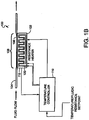
- FIG. 1A a schematic of a thermally-controlled variable restrictor 100 according to the invention is shown.
- This illustrative embodiment uses a single-stage Peltier thermo-electric heat pump 102 to heat or cool a length of tubing 104 having a flattened section 106 to effect a restriction element 108 in contact with a hot or cold face of the Peltier thermo-electric heat pump 102.
- the Peltier thermo-electric heat pump 102 in this illustrative embodiment, is used to heat or cool the restriction element 108, it is contemplated within the scope of the invention that the restriction element's 108 temperature could also be controlled by passing an electric current through the restriction element 108, or through an electrically resistive element in thermal contact with the restriction element 108.
- a temperature controller 110 uses a restriction element thermocouple 112 to monitor the temperature of the restriction element 108.
- the restriction element thermocouple 112 facilitates feedback to control the current applied to the Peltier thermo-electric heat pump 102 (and/or resistive heater, or cold/heat source(s)) maintaining a substantially constant restriction element temperature set point and hence substantially constant fluidic resistance set point.
- a resistive heater 120 can be used alone without a Peltier thermo-electric heat pump 102 relying on passive cooling to lower the temperature of the fluids within the restriction element 108, or in conjunction with the Peltier thermo-electric heat pump 102 where the heat pump 102 cools a thermal block in thermal contact with the flattened section 106 of tubing forming the fluidic restriction element 108.
- the resistive heater overcomes the cooling thermal current provided by the cold face of the Peltier thermo-electric heat pump 102 to heat the fluidic restriction.
- This alternative illustrative embodiment provides a more rapid thermal change by using a large thermal accumulator.
- several fluidic restriction elements can be cooled by a single Peltier thermo-electric heat pump and their individual temperatures can be controlled by individual resistance heaters that are in thermal contact with the individual fluidic restriction elements.
- the flattened length of tubing 106 forms the restriction element 108.
- various restriction elements can be used, such as, but not limited to, tubing with various internal geometric shapes, small-bore tubing, tubing packed with particles, a frit or the like.
- illustrative embodiments described here are mainly concerned with controlling flow in the ⁇ L/min to nL/min range, fixed restriction elements that will generate sufficient restriction in this flow regime are necessarily of small dimensions.
- microfluidic or MEMS-based planar structures such as planar serpentine channels or channels filled with a porous medium such as bed of particles or porous monolithic structure are within the scope of the invention.
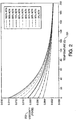
- FIG. 2 is a graphic representation between temperature 201 and viscosity 203 of water/acetonitrile mixtures representing how the viscosity decreases as the temperature is increased.
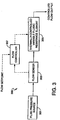
- FIG. 3 a schematic showing flow control system 300 employing the temperature-controlled variable restrictor according to the invention is shown.
- a number of commercial fluid flow controllers employ a design having a fluid pressure source 301 in fluid communication to a flow sensor 303, which is in fluid communication with a variable restrictor 305.
- the flow sensor 303 and variable restrictor 305 are in communication with a flow controller 307.
- a needle valve is used as a variable restrictor.
- the variable restrictor 305 is a thermally controlled variable restrictor, which in one illustrative embodiment uses a Peltier thermo-electric heat pump to vary its temperature.
- the temperature-controlled variable restrictor according to the invention is a solid-state system that is inherently sealed having no moving parts.
- the thermally controlled variable restrictor 305 according to the invention is able to be scaled to small flow rates very easily.
- variable restrictor 305 can be used within a flow control system 300 having a flow sensor 303 in fluid communication with a variable restrictor 305 according to the invention.
- commercially available low-flow flow rate sensors such as ⁇ -FLOW Mass Flow Meter, available from Bronkhorst, RUURLO, The Netherlands, Liquid Micro Mass Flow Meter SLG1430, available from Sensirion, Zurichm, Switzerland, or the like may be used in the flow control system 300.
- variable restrictor device within the illustrative examples are shown in single fluidic circuits, it should be appreciated by those skilled in the art that the variable restrictor device can be utilized in a parallel configuration within solvent gradient systems and such parallel configurations can be used to form a selected solvent gradient composition. Likewise, it will be appreciated that multiple variable restrictor device according to the invention can be utilized within a serial configuration within flow control systems.
- variable restrictor device within the illustrative examples are shown utilizing thermo-electric heat pumps or resistive electric elements to vary temperatures, it should be appreciated by those skilled in the art that temperature changes can be effected by the used of heated or cool gases or liquids.
- variable restrictor device within the illustrative examples are shown to vary flow rates by temperature induced viscosity changes in fluids flowing through such a device, it should be appreciated by those skilled in the art the fluid flow can be additionally effected by temperature induced physical changes in the configuration of fluid channels.
- variable restrictor device within the illustrative examples utilize a flow controller in communication with a flow sensor and a thermo-electric heat pump to adjust flow rate, it should be appreciated by those skilled in the art that fluid flow can be controlled by pre-selected temperatures within the thermal faces of the thermo-electric heat pump.
Landscapes
- Engineering & Computer Science (AREA)
- General Engineering & Computer Science (AREA)
- Mechanical Engineering (AREA)
- Chemical & Material Sciences (AREA)
- Dispersion Chemistry (AREA)
- Theoretical Computer Science (AREA)
- Physics & Mathematics (AREA)
- Fluid Mechanics (AREA)
- Flow Control (AREA)
- Fluid-Pressure Circuits (AREA)
- Control Of Temperature (AREA)
Applications Claiming Priority (2)
| Application Number | Priority Date | Filing Date | Title |
|---|---|---|---|
| US64580405P | 2005-01-21 | 2005-01-21 | |
| PCT/US2006/001564 WO2006078634A2 (en) | 2005-01-21 | 2006-01-18 | Temperature-controlled variable fluidic resistance device |
Publications (3)
| Publication Number | Publication Date |
|---|---|
| EP1838967A2 EP1838967A2 (en) | 2007-10-03 |
| EP1838967A4 EP1838967A4 (en) | 2011-11-02 |
| EP1838967B1 true EP1838967B1 (en) | 2017-12-13 |
Family
ID=36692781
Family Applications (1)
| Application Number | Title | Priority Date | Filing Date |
|---|---|---|---|
| EP06718617.1A Ceased EP1838967B1 (en) | 2005-01-21 | 2006-01-18 | Temperature-controlled variable fluidic resistance device |
Country Status (4)
| Country | Link |
|---|---|
| US (1) | US20080302423A1 (enExample) |
| EP (1) | EP1838967B1 (enExample) |
| JP (1) | JP2008528886A (enExample) |
| WO (1) | WO2006078634A2 (enExample) |
Cited By (1)
| Publication number | Priority date | Publication date | Assignee | Title |
|---|---|---|---|---|
| CN108778440A (zh) * | 2015-03-18 | 2018-11-09 | 弗朗索伊斯·帕尔曼蒂耶 | 高功效的色谱分离方法 |
Families Citing this family (15)
| Publication number | Priority date | Publication date | Assignee | Title |
|---|---|---|---|---|
| DE102008032098A1 (de) * | 2008-07-08 | 2010-02-25 | Hte Ag The High Throughput Experimentation Company | Teststand mit steuerbaren oder regelbaren Restriktoren |
| DE102008032097A1 (de) * | 2008-07-08 | 2010-01-14 | Hte Ag The High Throughput Experimentation Company | Teststand mit Gruppen von Restriktoren |
| EP2349569A1 (de) | 2008-07-08 | 2011-08-03 | HTE Aktiengesellschaft The High Throughput Experimentation Company | Teststand mit steuerbaren oder regelbaren restriktoren |
| EP2409204A2 (en) * | 2009-03-20 | 2012-01-25 | Avantium Holding B.v. | Flow controller assembly for microfluidic applications and system for performing a plurality of experiments in parallel |
| WO2013028450A1 (en) | 2011-08-19 | 2013-02-28 | Waters Technologies Corporation | Column manager with a multi-zone thermal system for use in liquid chromatography |
| CN103149949B (zh) * | 2013-01-09 | 2016-08-03 | 上海空间推进研究所 | 一种基于帕尔贴效应的气体微流量控制器 |
| WO2014158340A1 (en) * | 2013-03-12 | 2014-10-02 | Waters Technologies Corporation | Matching thermally modulated variable restrictors to chromatography separation columns |
| EP2972291A4 (en) * | 2013-03-12 | 2016-10-26 | Waters Technologies Corp | VARIABLE RESTRICTOR WITH THERMAL MODULATION |
| WO2014189738A2 (en) | 2013-05-22 | 2014-11-27 | Waters Technologies Corporation | Thermally modulated variable restrictor for normalization of dynamic split ratios |
| KR101573573B1 (ko) * | 2013-06-07 | 2015-12-07 | 성균관대학교산학협력단 | 유압액추에이터의 제어장치 |
| CN103807502A (zh) * | 2013-12-16 | 2014-05-21 | 浙江大学 | 热控可变流阻 |
| WO2015183290A1 (en) | 2014-05-29 | 2015-12-03 | Agilent Technologies, Inc. | Apparatus and method for introducing a sample into a separation unit of a chromatography system |
| US9764323B2 (en) | 2014-09-18 | 2017-09-19 | Waters Technologies Corporation | Device and methods using porous media in fluidic devices |
| CN105954448B (zh) * | 2016-06-22 | 2020-06-26 | 山东省计量科学研究院 | 一种恒温电导检测装置及检测方法 |
| US10935149B2 (en) * | 2018-03-15 | 2021-03-02 | University Of Washington | Temperature-actuated valve, fluidic device, and related methods of use |
Family Cites Families (10)
| Publication number | Priority date | Publication date | Assignee | Title |
|---|---|---|---|---|
| JPH0814337B2 (ja) * | 1988-11-11 | 1996-02-14 | 株式会社日立製作所 | 流体自体の相変化を利用した流路の開閉制御弁及び開閉制御方法 |
| US5316262A (en) * | 1992-01-31 | 1994-05-31 | Suprex Corporation | Fluid restrictor apparatus and method for making the same |
| US5975856A (en) * | 1997-10-06 | 1999-11-02 | The Aerospace Corporation | Method of pumping a fluid through a micromechanical valve having N-type and P-type thermoelectric elements for heating and cooling a fluid between an inlet and an outlet |
| DE19847952C2 (de) * | 1998-09-01 | 2000-10-05 | Inst Physikalische Hochtech Ev | Fluidstromschalter |
| JP3548858B2 (ja) * | 2001-01-22 | 2004-07-28 | 独立行政法人産業技術総合研究所 | 流量の制御方法及びそれに用いるマイクロバルブ |
| US6672076B2 (en) * | 2001-02-09 | 2004-01-06 | Bsst Llc | Efficiency thermoelectrics utilizing convective heat flow |
| US6557575B1 (en) * | 2001-11-19 | 2003-05-06 | Waters Investments Limited | Fluid flow control freeze/thaw valve for narrow bore capillaries or microfluidic devices |
| US6622746B2 (en) * | 2001-12-12 | 2003-09-23 | Eastman Kodak Company | Microfluidic system for controlled fluid mixing and delivery |
| JP4221184B2 (ja) * | 2002-02-19 | 2009-02-12 | 日本碍子株式会社 | マイクロ化学チップ |
| GB2414287B (en) * | 2002-12-09 | 2007-08-15 | Waters Investments Ltd | Peltier based freeze-thaw valves and method of use |
-
2006
- 2006-01-18 EP EP06718617.1A patent/EP1838967B1/en not_active Ceased
- 2006-01-18 US US11/814,434 patent/US20080302423A1/en not_active Abandoned
- 2006-01-18 JP JP2007552210A patent/JP2008528886A/ja active Pending
- 2006-01-18 WO PCT/US2006/001564 patent/WO2006078634A2/en not_active Ceased
Cited By (1)
| Publication number | Priority date | Publication date | Assignee | Title |
|---|---|---|---|---|
| CN108778440A (zh) * | 2015-03-18 | 2018-11-09 | 弗朗索伊斯·帕尔曼蒂耶 | 高功效的色谱分离方法 |
Also Published As
| Publication number | Publication date |
|---|---|
| WO2006078634A3 (en) | 2007-08-30 |
| EP1838967A2 (en) | 2007-10-03 |
| WO2006078634A2 (en) | 2006-07-27 |
| EP1838967A4 (en) | 2011-11-02 |
| US20080302423A1 (en) | 2008-12-11 |
| JP2008528886A (ja) | 2008-07-31 |
Similar Documents
| Publication | Publication Date | Title |
|---|---|---|
| EP1838967B1 (en) | Temperature-controlled variable fluidic resistance device | |
| JP3548858B2 (ja) | 流量の制御方法及びそれに用いるマイクロバルブ | |
| US8156964B2 (en) | Fast acting valve apparatuses | |
| CN101641596A (zh) | 微流体气相色谱系统体系结构 | |
| Ranjit et al. | Entropy generation on electromagnetohydrodynamic flow through a porous asymmetric micro-channel | |
| JP4741562B2 (ja) | 基板熱管理の方法 | |
| Schepperle et al. | Noninvasive platinum thin-film microheater/temperature sensor array for predicting and controlling flow boiling in microchannels | |
| Cao et al. | A micromachined Joule–Thomson cryogenic cooler with parallel two-stage expansion | |
| EP1261984B1 (en) | Substrate thermal management system | |
| JP2007523351A (ja) | オンチップ温度制御型液体クロマトグラフィー方法およびデバイス | |
| Cheng et al. | A bidirectional Knudsen pump with superior thermal management for micro-gas chromatography applications | |
| WO2015103086A1 (en) | Heated rotary valve for chromatography | |
| Jeong et al. | Experimental investigation of a heat switch based on the precise regulation of a liquid bridge | |
| US10401332B2 (en) | System and method for reducing chromatographic band broadening in separation devices | |
| JP2007247404A (ja) | マイクロポンプ | |
| Gui et al. | Microfluidic phase change valve with a two-level cooling/heating system | |
| US20040011977A1 (en) | Micro-fluidic valves | |
| US10274463B2 (en) | Static spatial thermal gradients for chromatography at the analytical scale | |
| Henning | Comprehensive model for thermopneumatic actuators and microvalves | |
| CN215987043U (zh) | 一种并行流体压力控制器 | |
| US5626166A (en) | Temperature control valve without moving parts | |
| Chang et al. | A Venturi microregulator array module for distributed pressure control | |
| Pharas et al. | Bi-directional gas pump driven by a thermoelectric material | |
| Brosten et al. | A numerical flow model and experimental results of a cryogenic micro-valve for distributed cooling applications | |
| Schnepf et al. | Closed-Loop, Axial Temperature Control of Etched Silicon Microcolumn for Tunable Thermal Gradient Gas Chromatography |
Legal Events
| Date | Code | Title | Description |
|---|---|---|---|
| PUAI | Public reference made under article 153(3) epc to a published international application that has entered the european phase |
Free format text: ORIGINAL CODE: 0009012 |
|
| 17P | Request for examination filed |
Effective date: 20070718 |
|
| AK | Designated contracting states |
Kind code of ref document: A2 Designated state(s): AT BE BG CH CY CZ DE DK EE ES FI FR GB GR HU IE IS IT LI LT LU LV MC NL PL PT RO SE SI SK TR |
|
| AX | Request for extension of the european patent |
Extension state: AL BA HR MK YU |
|
| R17D | Deferred search report published (corrected) |
Effective date: 20070830 |
|
| DAX | Request for extension of the european patent (deleted) | ||
| RBV | Designated contracting states (corrected) |
Designated state(s): DE FR GB |
|
| RAP1 | Party data changed (applicant data changed or rights of an application transferred) |
Owner name: WATERS TECHNOLOGIES CORPORATION |
|
| A4 | Supplementary search report drawn up and despatched |
Effective date: 20110929 |
|
| RIC1 | Information provided on ipc code assigned before grant |
Ipc: F16K 99/00 20060101ALI20110923BHEP Ipc: F15C 1/04 20060101AFI20110923BHEP Ipc: F16K 13/10 20060101ALI20110923BHEP |
|
| 17Q | First examination report despatched |
Effective date: 20130108 |
|
| GRAP | Despatch of communication of intention to grant a patent |
Free format text: ORIGINAL CODE: EPIDOSNIGR1 |
|
| INTG | Intention to grant announced |
Effective date: 20160411 |
|
| GRAS | Grant fee paid |
Free format text: ORIGINAL CODE: EPIDOSNIGR3 |
|
| GRAA | (expected) grant |
Free format text: ORIGINAL CODE: 0009210 |
|
| AK | Designated contracting states |
Kind code of ref document: B1 Designated state(s): DE FR GB |
|
| REG | Reference to a national code |
Ref country code: GB Ref legal event code: FG4D |
|
| REG | Reference to a national code |
Ref country code: DE Ref legal event code: R096 Ref document number: 602006054323 Country of ref document: DE |
|
| REG | Reference to a national code |
Ref country code: FR Ref legal event code: PLFP Year of fee payment: 13 |
|
| REG | Reference to a national code |
Ref country code: DE Ref legal event code: R097 Ref document number: 602006054323 Country of ref document: DE |
|
| PLBE | No opposition filed within time limit |
Free format text: ORIGINAL CODE: 0009261 |
|
| STAA | Information on the status of an ep patent application or granted ep patent |
Free format text: STATUS: NO OPPOSITION FILED WITHIN TIME LIMIT |
|
| 26N | No opposition filed |
Effective date: 20180914 |
|
| PGFP | Annual fee paid to national office [announced via postgrant information from national office to epo] |
Ref country code: FR Payment date: 20181220 Year of fee payment: 14 |
|
| PG25 | Lapsed in a contracting state [announced via postgrant information from national office to epo] |
Ref country code: FR Free format text: LAPSE BECAUSE OF NON-PAYMENT OF DUE FEES Effective date: 20200131 |
|
| P01 | Opt-out of the competence of the unified patent court (upc) registered |
Effective date: 20230612 |
|
| PGFP | Annual fee paid to national office [announced via postgrant information from national office to epo] |
Ref country code: GB Payment date: 20231219 Year of fee payment: 19 |
|
| PGFP | Annual fee paid to national office [announced via postgrant information from national office to epo] |
Ref country code: DE Payment date: 20231219 Year of fee payment: 19 |
|
| REG | Reference to a national code |
Ref country code: DE Ref legal event code: R119 Ref document number: 602006054323 Country of ref document: DE |
|
| GBPC | Gb: european patent ceased through non-payment of renewal fee |
Effective date: 20250118 |
|
| PG25 | Lapsed in a contracting state [announced via postgrant information from national office to epo] |
Ref country code: DE Free format text: LAPSE BECAUSE OF NON-PAYMENT OF DUE FEES Effective date: 20250801 |
|
| PG25 | Lapsed in a contracting state [announced via postgrant information from national office to epo] |
Ref country code: GB Free format text: LAPSE BECAUSE OF NON-PAYMENT OF DUE FEES Effective date: 20250118 |