EP1837462A2 - Electric door opener - Google Patents
Electric door opener Download PDFInfo
- Publication number
- EP1837462A2 EP1837462A2 EP06026394A EP06026394A EP1837462A2 EP 1837462 A2 EP1837462 A2 EP 1837462A2 EP 06026394 A EP06026394 A EP 06026394A EP 06026394 A EP06026394 A EP 06026394A EP 1837462 A2 EP1837462 A2 EP 1837462A2
- Authority
- EP
- European Patent Office
- Prior art keywords
- actuating
- pawl
- lever
- door opener
- point
- Prior art date
- Legal status (The legal status is an assumption and is not a legal conclusion. Google has not performed a legal analysis and makes no representation as to the accuracy of the status listed.)
- Granted
Links
- 230000000903 blocking effect Effects 0.000 claims description 27
- 230000002035 prolonged effect Effects 0.000 claims description 2
- 238000000034 method Methods 0.000 description 4
- 230000005540 biological transmission Effects 0.000 description 2
- 241001295925 Gegenes Species 0.000 description 1
- 230000000052 comparative effect Effects 0.000 description 1
- 230000003247 decreasing effect Effects 0.000 description 1
- 239000002655 kraft paper Substances 0.000 description 1
- 238000004904 shortening Methods 0.000 description 1
- 230000007704 transition Effects 0.000 description 1
- 230000001960 triggered effect Effects 0.000 description 1
Images


Classifications
-
- E—FIXED CONSTRUCTIONS
- E05—LOCKS; KEYS; WINDOW OR DOOR FITTINGS; SAFES
- E05B—LOCKS; ACCESSORIES THEREFOR; HANDCUFFS
- E05B47/00—Operating or controlling locks or other fastening devices by electric or magnetic means
- E05B47/0046—Electric or magnetic means in the striker or on the frame; Operating or controlling the striker plate
- E05B47/0047—Striker rotating about an axis parallel to the wing edge
Definitions
- Such an electric door opener is regularly mounted on or behind a closing strip or a striking plate, which has a passage opening into which engages the latch of the door lock in the closed position.
- the locking lug of the opener trap then forms the latch catch, wherein the door can be opened in the blocking position of the pawl only by pulling back the latch case, for example a pusher or a key of the door lock.
- the pivotable ⁇ ffnerfalle released by pressing the Entriegelungsantriebes so the door can be opened from the outside even in the pre-pressed closed position of the latch, so that the door can be pressed from the outside without lock latch actuation, if, for example, in Inside of a building the release drive is triggered.
- the unlocking drive is, for example, an electromagnetic drive (for example a lifting magnet), which transfers the pawl from the blocking position into the release position.
- the actuating plunger presses on the pawl or pulls on the pawl to transfer them from the blocking position to the release position.
- the pawl is then transferred under the action of the spring from the release position back into the blocking position.
- the plunger regularly acts directly along the actuation axis on an engagement point on the actuation axis on the detent pawl.
- relatively high spring forces of the spring are required.
- This in turn requires relatively strong lifting magnets in order to overcome the counterforce of the spring in the course of unlocking.
- in the blocking position of the blocking lever is pressed with its blocking edge by, for example, the force of a rubber seal the door with a relatively high force against the locking edge on the pawl, so that these must be overcome upon actuation of the solenoid.
- very strong lifting magnets are often required, which have corresponding sizes. -
- the invention wants to remedy the situation.
- the invention has for its object to provide an electric door opener of the type described above, which allows a simple and compact design proper unlocking of the door opener.
- the invention teaches in a generic electric door opener of the type described above, that the actuating plunger during the actuating stroke or during a first Betuschistssteilhubes at least at a first application point of the pawl engages, which is spaced to form an elongated lever arm by a predetermined amount of the actuating axis, in the direction away from the pivot axis of the pawl.
- the invention is based on the recognition that with an actuating drive, for example with a solenoid, predetermined power or predetermined operating force, the release of the pawl can be done reliably even with large opposing forces when the connection of the actuating plunger to the pawl under extension of the Lever arm takes place.
- Lever here means the distance between the point and the pivot axis of the pawl. This is achieved by the actuating tappet no longer working directly along its actuating axis against the pawl, so that the point of the pawl is no longer on the operating axis. Rather, it is achieved in the context of the invention that the point on the pawl has an increased distance from the pivot axis, so that a total of an extended lever arm is used. This is achieved for example by appropriate design of the actuating plunger or by connecting an actuating element or a transmission element to the actuating plunger, which may be formed, for example, L-shaped or angular.
- an offset between on the one hand the actuating axis of the actuating plunger and on the other hand the point of application to the pawl is generated by this configuration of the actuating plunger or by connecting an actuating element. This offset corresponds to the Hebelarmverinrung.
- the actuating tappet engages after the first operating part stroke during at least one second operating part stroke at least at a second point of the pawl, which in the region of the actuating axis is located or spaced to form a shortened lever arm by a predetermined amount of the actuating axis, in the direction of the pivot axis of the pawl out.
- the invention is based on the recognition that due to the general leverage laws with the above-described enlargement of the lever arm in the region of the first point of attack a correspondingly enlarged actuating stroke is required to pivot the pawl to the predetermined pivot angle.
- a relatively short operating stroke can be used again overall.
- the invention has recognized that the above-described high release forces must be applied to a particular extent at the beginning of the triggering or unlocking process and consequently during the first Bet Oberistssteilhubes, while it is then sufficient in the course of the triggering process regularly, with relatively low release forces work because, for example, the triggering counteracting friction force between pawl and locking lever has already been overcome, so that then only has to be worked against the force of the tension spring.
- the actuating plunger with the interposition of an actuating element for example an actuating head or an actuating lever works on the pawl, wherein this actuating element has a first, corresponding to the first point of application actuating surface and optionally a second, corresponding to the second point of application actuating surface.
- an actuator connected to the actuating tappet consequently serves to "displace" the point of action away from the actuating axis, either to extend the lever arm or to shorten the lever arm.
- the actuating element is designed as a T-shaped actuating head, for example.
- Such an essentially T-shaped actuating head then preferably has in its end regions of the T-bar two spaced-apart actuating surfaces, which correspond to the two spaced engagement points on the pawl.
- the actuating head can be rigidly connected to the actuating plunger according to a first embodiment of the invention. It is possible to work with a separately manufactured actuator head, which is fixed or detachably connected to the actuating plunger. But it is also possible to use an integrally formed on the actuating plunger actuating head.
- the actuating element is designed as a relative to the actuating plunger and / or to the pawl movable actuating lever.
- the actuating lever is pivotally hinged to the pawl and is also pivotally supported on the ⁇ ffnergephaseuse.
- the spring which acts on the pawl, between the pawl on the one hand and the operating lever on the other hand is arranged.
- the actuating lever is designed as an actuating spring, for example leaf spring, which preferably is attached to the ⁇ ffnergephaseuse.
- the pawl is in its initial position with its first point near the attachment point of the leaf spring to the bearing housing on the leaf spring.
- On the opposite end of the leaf spring now acts the actuating plunger.
- the leaf spring transmits the release force in the area of the first point of attack with increased lever arm.
- the leaf spring rests against the pawl in a second point, which is closer to the pivot axis of the pawl.
- an electric door opener is shown with Bertd Wegbarer latch 1, wherein such an electric door opener, for example, is attached to the back of a strike plate or on a closing strip in the region of a passage opening of the closing strip.
- the electric door opener has a ⁇ ffnergephaseuse 2 and a pivotally mounted in the ⁇ ffnergephaseuse (spring-loaded) ⁇ ffnerfalle 3 with a locking lug 4, which is engaged behind by the latch in pre-pressed closed position.
- a pivotally mounted (spring-loaded) blocking lever 5 and acting on the blocking lever 5 (spring-loaded) pawl 6 is provided in the ⁇ ffnergephinuse 2 .
- Fig. 3 shows the door opener in the blocking position, in which case the blocking lever 5 with its locking edge 8 or locking lug against a corresponding locking edge 9 or locking nose of the pawl 6 is applied, so that the blocking lever 5 can not be pivoted down and the opener 3 accordingly is blocked against pivoting.
- Fig. 3 shows the door opener in the blocking position, in which case the blocking lever 5 with its locking edge 8 or locking lug against a corresponding locking edge 9 or locking nose of the pawl 6 is applied, so that the blocking lever 5 can not be pivoted down and the opener 3 accordingly is blocked against pivoting.
- the effective lever arm is greater by the amount ⁇ L 1 than in the case where the actuating tappet would work directly against the pawl on its actuating axis. It then follows, taking into account the general leverage laws that at a given power or operating force of the solenoid 7, an increased force can be applied to the pawl during the first operating part stroke.
- the actuating plunger 13 acts after the first operating part during a second Betjanssteilhubes at a second point A 2 of the pawl 6, which is spaced to form a shortened lever arm L 2 by a predetermined amount .DELTA.L 2 of the actuating axis, and Although in the direction of the pivot axis 10 of the pawl 6 back.
- this second point is spaced by the amount .DELTA.L 2 of the actuating axis 12, so that is now working with a shortened lever arm L 2 .
- the actuating plunger 13 operates with the interposition of an actuating element 14 on the pawl 6, this actuator 14 is responsible for the offset of the point or the points A 1 , A 2 and consequently for the extension and / or shortening of the lever arm.
- the actuating element 14 in the exemplary embodiments, a first, corresponding to the first point of application A 1 actuating surface B 1 and a second, with the second point of application A 2 corresponding actuating surface B 2 .
- the actuating element 14 is designed as an actuating head 14, which is rigidly connected to the actuating plunger 13. 2 to 4 that the actuating head 14 here (together with the actuating plunger) is T-shaped, wherein the two actuating surfaces B 1 , B 2 are each connected end to the T-bar. It is understood that the configuration of the actuating surfaces B 1 , B 2 and the shape of the pawl 6 are coordinated with each other in order to achieve the desired operating characteristic. It is expedient if - as shown in FIGS. 3 and 4 - the pawl 6 is formed curved overall or profiled or has each other at a predetermined angle employed areas. In this way it is ensured that a perfect power transmission takes place.
- the surfaces of the pawl 6 and the actuating head 14 to match so that a continuous transition between the first actuating stroke and the second actuating stroke, so that, for example, with a (steadily) decreasing lever arm is used.
- the actuating element 14 is designed in each case as an actuating lever 14a, 14b.
- Fig. 5 shows an embodiment in which the actuating lever 14a is pivotally hinged as a rigid lever to the pawl 6 and beyond pivotally supported on the ⁇ ffnergephaseuse 2.
- the pawl 6 acted upon spring 11 is here between the actuating lever 14a on the one hand and pawl 6 on the other hand arranged.
- This configuration makes it possible to work with relatively weak springs and yet to generate high restoring forces. It can be seen in Fig. 5 that at the beginning of the tripping operation of the actuating plunger 13 engages the actuating lever 14a at a first point A 1 with extended lever arm, namely in the region of the pivot point D between the actuating lever 14a and pawl 6.
- Fig. 6 shows a further embodiment of the invention, in which the actuating element is designed as an actuating spring 14b in the embodiment as a leaf spring.
- This actuating spring 14b is also supported on the opener housing 2 or fastened to the opener housing.
- the actuating tappet 13 first works via the leaf spring 14b at a first point of application A 1 on the pawl 6, which provides for an enlarged lever arm.
- the leaf spring strikes in a region closer to the pivot axis A 2 to the pawl, so that you can then work with reduced lever arm.
- Reduced lever means here, reduced with respect to the initially extended lever arm, wherein the reduced lever arm is still greater than or equal to the "conventional" lever arm with lying on the operating axis point.
Landscapes
- Lock And Its Accessories (AREA)
Abstract
Description
Die Erfindung betrifft einen elektrischen Türöffner für ein Türschloss mit zurückdrückbarer Schlossfalle mit
- einem Öffnergehäuse,
- einer schwenkbar gelagerten Öffnerfalle mit einer Sperrnase, welche von der Schlossfalle in vorgedrückter Schließstellung hintergriffen wird,
- einem schwenkbar gelagerten Blockierhebel und einer auf den Blockierhebel wirkenden Sperrklinke, welche durch Betätigung eines Entriegelungsantriebes aus einer Sperrstellung in eine Freigabestellung bringbar ist, wobei der Blockierhebel die Öffnerfalle in Sperrstellung der Sperrklinke blockiert und in Freigabestellung der Sperrklinke freigibt,
- a normally closed housing,
- a pivotally mounted Öffnerfalle with a locking nose, which is engaged behind by the latch in pre-pressed closed position,
- a pivotally mounted blocking lever and a locking pawl acting on the blocking lever, which can be brought from a blocking position into a release position by actuating an unlocking drive, wherein the blocking lever blocks the opening latch in the blocking position of the pawl and releases it in the release position of the pawl,
Ein solcher elektrischer Türöffner wird regelmäßig an bzw. hinter einer Schließleiste bzw. einem Schließblech montiert, welches eine Durchtrittsöffnung aufweist, in welche die Schlossfalle des Türschlosses in Schließstellung eingreift. Die Sperrnase der Öffnerfalle bildet dann die Fallenrast, wobei sich die Tür in Sperrstellung der Sperrklinke nur durch Zurückziehen der Schlossfalle über zum Beispiel einen Drücker oder einen Schlüssel des Türschlosses öffnen lässt. Wird die schwenkbare Öffnerfalle jedoch durch Betätigung des Entriegelungsantriebes freigegeben, so lässt sich die Tür auch in vorgedrückter Schließstellung der Schlossfalle von außen öffnen, so dass die Tür von außen auch ohne Schlossfallenbetätigung aufgedrückt werden kann, wenn zum Beispiel im Inneren eines Gebäudes der Entriegelungsantrieb ausgelöst wird. Bei dem Entriegelungsantrieb handelt es sich beispielsweise um einen elektromagnetischen Antrieb (zum Beispiel einen Hubmagneten), welcher die Sperrklinke aus der Sperrstellung in die Freigabestellung überführt. Dazu drückt der Betätigungsstößel auf die Sperrklinke bzw. zieht an der Sperrklinke, um diese aus der Sperrstellung in die Freigabestellung zu überführen. Nach Betätigung des Betätigungsantriebes und folglich nach Zurückziehen des Betätigungsstößels wird die Sperrklinke dann unter der Wirkung der Feder aus der Freigabestellung zurück in die Sperrstellung überführt.Such an electric door opener is regularly mounted on or behind a closing strip or a striking plate, which has a passage opening into which engages the latch of the door lock in the closed position. The locking lug of the opener trap then forms the latch catch, wherein the door can be opened in the blocking position of the pawl only by pulling back the latch case, for example a pusher or a key of the door lock. However, if the pivotable Öffnerfalle released by pressing the Entriegelungsantriebes, so the door can be opened from the outside even in the pre-pressed closed position of the latch, so that the door can be pressed from the outside without lock latch actuation, if, for example, in Inside of a building the release drive is triggered. The unlocking drive is, for example, an electromagnetic drive (for example a lifting magnet), which transfers the pawl from the blocking position into the release position. For this purpose, the actuating plunger presses on the pawl or pulls on the pawl to transfer them from the blocking position to the release position. After actuation of the actuating drive and thus after retraction of the actuating plunger, the pawl is then transferred under the action of the spring from the release position back into the blocking position.
Bei den aus der Praxis bekannten elektrischen Türöffnern wirkt der Stößel regelmäßig unmittelbar entlang der Betätigungsachse auf einen auf der Betätigungsachse liegenden Angriffspunkt an der Sperrklinke. Um eine einwandfreie Rückführung der Sperrklinke zu gewährleisten, sind verhältnismäßig hohe Federkräfte der Feder erforderlich. Dieses verlangt wiederum verhältnismäßig starke Hubmagneten, um im Zuge der Entriegelung die Gegenkraft der Feder zu überwinden. Hinzu kommt, dass in Sperrstellung der Blockierhebel mit seiner Blockierkante durch beispielsweise die Kraft einer Gummidichtung der Tür mit verhältnismäßig hoher Kraft gegen die Sperrkante an der Sperrklinke gedrückt wird, so dass auch diese bei Betätigung des Hubmagneten überwunden werden muss. Um eine einwandfreie Funktion zu gewährleisten, sind daher häufig sehr starke Hubmagneten erforderlich, die dementsprechende Baugrößen aufweisen. - Hier will die Erfindung Abhilfe schaffen.In the case of the electric door openers known from practice, the plunger regularly acts directly along the actuation axis on an engagement point on the actuation axis on the detent pawl. To ensure proper return of the pawl, relatively high spring forces of the spring are required. This in turn requires relatively strong lifting magnets in order to overcome the counterforce of the spring in the course of unlocking. In addition, in the blocking position of the blocking lever is pressed with its blocking edge by, for example, the force of a rubber seal the door with a relatively high force against the locking edge on the pawl, so that these must be overcome upon actuation of the solenoid. To ensure proper operation, therefore, very strong lifting magnets are often required, which have corresponding sizes. - Here the invention wants to remedy the situation.
Der Erfindung liegt die Aufgabe zugrunde, einen elektrischen Türöffner der eingangs beschriebenen Art zu schaffen, welcher bei einfachem und kompaktem Aufbau eine einwandfreie Entriegelung des Türöffners ermöglicht.The invention has for its object to provide an electric door opener of the type described above, which allows a simple and compact design proper unlocking of the door opener.
Zur Lösung dieser Aufgabe lehrt die Erfindung bei einem gattungsgemäßen elektrischen Türöffner der eingangs beschriebenen Art, dass der Betätigungsstößel während des Betätigungshubes oder während eines ersten Betätigungsteilhubes zumindest an einem ersten Angriffspunkt der Sperrklinke angreift, welcher unter Bildung eines verlängerten Hebelarmes um ein vorgegebenes Maß von der Betätigungsachse beabstandet ist, und zwar in Richtung von der Schwenkachse der Sperrklinke weg. - Dabei geht die Erfindung von der Erkenntnis aus, dass mit einem Betätigungsantrieb, zum Beispiel mit einem Hubmagneten, vorgegebener Leistung bzw. vorgegebener Betätigungskraft die Auslösung der Sperrklinke auch bei großen Gegenkräften zuverlässig erfolgen kann, wenn die Anbindung des Betätigungsstößels an die Sperrklinke unter Verlängerung des Hebelarmes erfolgt. Hebelarm meint hier den Abstand zwischen dem Angriffspunkt und der Schwenkachse der Sperrklinke. Dieses gelingt dadurch, dass der Betätigungsstößel nicht mehr unmittelbar entlang seiner Betätigungsachse gegen die Sperrklinke arbeitet, so dass der Angriffspunkt der Sperrklinke nicht mehr auf der Betätigungsachse liegt. Vielmehr wird im Rahmen der Erfindung erreicht, dass der Angriffspunkt auf der Sperrklinke einen vergrößerten Abstand von der Schwenkachse besitzt, so dass insgesamt mit einem verlängerten Hebelarm gearbeitet wird. Dieses gelingt beispielsweise durch entsprechende Ausgestaltung des Betätigungsstößels bzw. durch Anschluss eines Betätigungselementes bzw. eines Übertragungselementes an den Betätigungsstößel, welches zum Beispiel L-förmig oder auch winkelförmig ausgebildet sein kann. Jedenfalls wird durch diese Ausgestaltung des Betätigungsstößels bzw. durch Anschluss eines Betätigungselementes ein Versatz zwischen einerseits der Betätigungsachse des Betätigungsstößels und andererseits dem Angriffspunkt an der Sperrklinke erzeugt. Dieser Versatz entspricht der Hebelarmverlängerung.To solve this problem, the invention teaches in a generic electric door opener of the type described above, that the actuating plunger during the actuating stroke or during a first Betätigungssteilhubes at least at a first application point of the pawl engages, which is spaced to form an elongated lever arm by a predetermined amount of the actuating axis, in the direction away from the pivot axis of the pawl. - The invention is based on the recognition that with an actuating drive, for example with a solenoid, predetermined power or predetermined operating force, the release of the pawl can be done reliably even with large opposing forces when the connection of the actuating plunger to the pawl under extension of the Lever arm takes place. Lever here means the distance between the point and the pivot axis of the pawl. This is achieved by the actuating tappet no longer working directly along its actuating axis against the pawl, so that the point of the pawl is no longer on the operating axis. Rather, it is achieved in the context of the invention that the point on the pawl has an increased distance from the pivot axis, so that a total of an extended lever arm is used. This is achieved for example by appropriate design of the actuating plunger or by connecting an actuating element or a transmission element to the actuating plunger, which may be formed, for example, L-shaped or angular. In any case, an offset between on the one hand the actuating axis of the actuating plunger and on the other hand the point of application to the pawl is generated by this configuration of the actuating plunger or by connecting an actuating element. This offset corresponds to the Hebelarmverlängerung.
Nach einem weiteren Vorschlag der Erfindung, welchem besondere Bedeutung zukommt, greift der Betätigungsstößel nach dem ersten Betätigungsteilhub während zumindest eines zweiten Betätigungsteilhubes zumindest an einem zweiten Angriffspunkt der Sperrklinke an, welcher im Bereich der Betätigungsachse liegt oder unter Bildung eines verkürzten Hebelarmes um ein vorgegebenes Maß von der Betätigungsachse beabstandet ist, und zwar in Richtung zur Schwenkachse der Sperrklinke hin. Dabei geht die Erfindung von der Erkenntnis aus, dass aufgrund der allgemeinen Hebelgesetze mit der oben beschriebenen Vergrößerung des Hebelarmes im Bereich des ersten Angriffspunktes ein entsprechend vergrößerter Betätigungshub erforderlich ist, um die Sperrklinke um den vorgegebenen Schwenkwinkel zu verschwenken. Wird nun im Bereich eines ersten Betätigungshubes mit einem vergrößerten Hebelarm und dann im Bereich eines zweiten Betätigungshubes mit einem verkürzten Hebelarm gearbeitet, so kann insgesamt wieder mit einem verhältnismäßig kurzen Betätigungshub gearbeitet werden. Dabei hat die Erfindung erkannt, dass die oben beschriebenen hohen Auslösekräfte in besonderem Maße zu Beginn des Auslöse- bzw. Entriegelungsvorganges und folglich während des ersten Betätigungsteilhubes aufgebracht werden müssen, während es dann im weiteren Verlauf des Auslösevorganges regelmäßig ausreichend ist, mit verhältnismäßig geringen Auslösekräften zu arbeiten, da beispielsweise die der Auslösung entgegenwirkende Reibungskraft zwischen Sperrklinke und Blockierhebel bereits überwunden wurde, so dass dann nur noch gegen die Kraft der Spannfeder gearbeitet werden muss.According to a further proposal of the invention, which is of particular importance, the actuating tappet engages after the first operating part stroke during at least one second operating part stroke at least at a second point of the pawl, which in the region of the actuating axis is located or spaced to form a shortened lever arm by a predetermined amount of the actuating axis, in the direction of the pivot axis of the pawl out. The invention is based on the recognition that due to the general leverage laws with the above-described enlargement of the lever arm in the region of the first point of attack a correspondingly enlarged actuating stroke is required to pivot the pawl to the predetermined pivot angle. If a shortened lever arm is then used in the region of a first actuating stroke with an enlarged lever arm and then in the region of a second actuating stroke, a relatively short operating stroke can be used again overall. In this case, the invention has recognized that the above-described high release forces must be applied to a particular extent at the beginning of the triggering or unlocking process and consequently during the first Betätigungssteilhubes, while it is then sufficient in the course of the triggering process regularly, with relatively low release forces work because, for example, the triggering counteracting friction force between pawl and locking lever has already been overcome, so that then only has to be worked against the force of the tension spring.
Um die Auslösung der Sperrklinke unter Berücksichtigung des beschriebenen verlängerten Hebelarmes und ggf. unter Berücksichtigung des verkürzten Hebelarmes zu gewährleisten, ist es zweckmäßig, wenn der Betätigungsstößel unter Zwischenschaltung eines Betätigungselementes, zum Beispiel eines Betätigungskopfes oder eines Betätigungshebels auf die Sperrklinke arbeitet,
wobei dieses Betätigungselement eine erste, mit dem ersten Angriffspunkt korrespondierende Betätigungsfläche und ggf. eine zweite, mit dem zweiten Angriffspunkt korrespondierende Betätigungsfläche aufweist. Ein solches an dem Betätigungsstößel angeschlossenes Betätigungselement dient folglich der "Verschiebung" des Angriffspunktes von der Betätigungsachse weg, entweder zur Verlängerung des Hebelarmes oder zur Verkürzung des Hebelarmes. Insofern kann es sich - wie oben bereits beschrieben - um ein L-förmiges oder winkelförmiges Betätigungselement handeln, welches auch Bestandteil des Betätigungsstößels sein kann. Für die zweistufige bzw. mehrstufige Auslösung unter Berücksichtigung eines ersten Angriffspunktes und eines zweiten Angriffspunktes kann es zweckmäßig sein, wenn das Betätigungselement als zum Beispiel T-förmiger Betätigungskopf ausgebildet ist. Ein solcher im Wesentlichen T-förmig ausgebildeter Betätigungskopf weist dann vorzugsweise in seinen Endbereichen des T-Steges zwei voneinander beabstandete Betätigungsflächen auf, welche mit den beiden beabstandeten Angriffspunkten auf der Sperrklinke korrespondieren.In order to ensure the release of the pawl taking into account the described extended lever arm and possibly taking into account the shortened lever arm, it is expedient if the actuating plunger with the interposition of an actuating element, for example an actuating head or an actuating lever works on the pawl,
wherein this actuating element has a first, corresponding to the first point of application actuating surface and optionally a second, corresponding to the second point of application actuating surface. Such an actuator connected to the actuating tappet consequently serves to "displace" the point of action away from the actuating axis, either to extend the lever arm or to shorten the lever arm. In this respect, it can - as already described above - be an L-shaped or angular actuator, which may also be part of the actuating plunger. For the two-stage or multi-stage triggering taking into account a first point of attack and a second point of application, it may be expedient if the actuating element is designed as a T-shaped actuating head, for example. Such an essentially T-shaped actuating head then preferably has in its end regions of the T-bar two spaced-apart actuating surfaces, which correspond to the two spaced engagement points on the pawl.
Der Betätigungskopf kann nach einer ersten Ausführungsform der Erfindung starr an den Betätigungsstößel angeschlossen sein. Dabei besteht die Möglichkeit, mit einem separat gefertigten Betätigungskopf zu arbeiten, welcher fest oder auch lösbar mit dem Betätigungsstößel verbunden wird. Es besteht aber auch die Möglichkeit, einen einstückig an den Betätigungsstößel angeformten Betätigungskopf einzusetzen.The actuating head can be rigidly connected to the actuating plunger according to a first embodiment of the invention. It is possible to work with a separately manufactured actuator head, which is fixed or detachably connected to the actuating plunger. But it is also possible to use an integrally formed on the actuating plunger actuating head.
Nach einer abgewandelten Ausführungsform der Erfindung ist das Betätigungselement als relativ zu dem Betätigungsstößel und/oder zu der Sperrklinke beweglicher Betätigungshebel ausgebildet. Dabei besteht die Möglichkeit, dass der Betätigungshebel schwenkbar an die Sperrklinke angelenkt ist und außerdem drehpunktartig an dem Öffnergehäuse abgestützt ist. Bei einer solchen Ausführungsform ist es zweckmäßig, wenn die Feder, welche auf die Sperrklinke wirkt, zwischen Sperrklinke einerseits und Betätigungshebel andererseits angeordnet ist.According to a modified embodiment of the invention, the actuating element is designed as a relative to the actuating plunger and / or to the pawl movable actuating lever. There is the possibility that the actuating lever is pivotally hinged to the pawl and is also pivotally supported on the Öffnergehäuse. In such an embodiment, it is expedient if the spring which acts on the pawl, between the pawl on the one hand and the operating lever on the other hand is arranged.
In anderer Ausgestaltung besteht die Möglichkeit, dass der Betätigungshebel als Betätigungsfeder, zum Beispiel Blattfeder ausgebildet ist, welche vorzugsweise an dem Öffnergehäuse befestigt ist. Die Sperrklinke liegt dabei in ihrer Ausgangsstellung mit ihrem ersten Angriffspunkt in der Nähe des Befestigungspunktes der Blattfeder an dem Lagergehäuse an der Blattfeder an. Auf das gegenüberliegende Ende der Blattfeder wirkt nun der Betätigungsstößel. Zu Beginn der Auslösebewegung überträgt die Blattfeder die Auslösekraft in den Bereich des ersten Angriffspunktes mit vergrößertem Hebelarm. Im weiteren Verlauf der Auslösebewegung besteht dann die Möglichkeit, dass die Blattfeder in einem zweiten Angriffspunkt, welcher näher an der Schwenkachse der Sperrklinke liegt, gegen die Sperrklinke anliegt.In another embodiment, there is the possibility that the actuating lever is designed as an actuating spring, for example leaf spring, which preferably is attached to the Öffnergehäuse. The pawl is in its initial position with its first point near the attachment point of the leaf spring to the bearing housing on the leaf spring. On the opposite end of the leaf spring now acts the actuating plunger. At the beginning of the release movement, the leaf spring transmits the release force in the area of the first point of attack with increased lever arm. In the further course of the release movement then there is the possibility that the leaf spring rests against the pawl in a second point, which is closer to the pivot axis of the pawl.
Im Folgenden wird die Erfindung anhand von lediglich Ausführungsbeispiele ndarstellenden Zeichnungen näher erläutert. Es zeigen
- Fig. 1
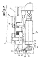
- einen elektrischen Türöffner in einer perspektivischen Darstellung mit geöffnetem Öffnergehäuse,
- Fig. 2
- die Hebelmechanik des Türöffners nach Fig. 1 ohne Öffnergehäuse in einer Rückansicht,
- Fig. 3
- einen vergrößerten Ausschnitt aus dem Gegenstand nach Fig. 1 in einer ersten Funktionsstellung,
- Fig. 4
- den Gegenstand nach Fig. 3 in einer zweiten Funktionsstellung,
- Fig. 5
- den Gegenstand nach Fig. 3 in einer abgewandelten Ausführungsform und
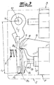
- Fig. 6
- den Gegenstand nach Fig. 3 in einer weiteren Ausführungsform.
- Fig. 1
- an electric door opener in a perspective view with an opener housing,
- Fig. 2
- the lever mechanism of the door opener according to FIG. 1 without normally closed housing in a rear view,
- Fig. 3
- an enlarged detail of the article of FIG. 1 in a first functional position,
- Fig. 4
- the article of FIG. 3 in a second functional position,
- Fig. 5
- the article of Fig. 3 in a modified embodiment and
- Fig. 6
- the article of Fig. 3 in a further embodiment.
In den Figuren ist ein elektrischer Türöffner mit zurückdrückbarer Schlossfalle 1 dargestellt, wobei ein solcher elektrischer Türöffner beispielsweise rückseitig an einem Schließblech bzw. an einer Schließleiste im Bereich einer Durchtrittsöffnung der Schließleiste befestigt wird. Der elektrische Türöffner weist ein Öffnergehäuse 2 sowie eine in dem Öffnergehäuse schwenkbar gelagerte (federbelastete) Öffnerfalle 3 mit einer Sperrnase 4 auf, welche von der Schlossfalle in vorgedrückter Schließstellung hintergriffen wird. Ferner ist in dem Öffnergehäuse 2 ein schwenkbar gelagerter (federbelasteter) Blockierhebel 5 sowie eine auf den Blockierhebel 5 wirkende (federbelastete) Sperrklinke 6 vorgesehen. Auf die Sperrklinke arbeitet ein Entriegelungsantrieb 7, so dass durch Betätigung des Entriegelungsantriebes 7 die Sperrklinke 6 aus einer Sperrstellung in eine Freigabestellung gebracht wird, wobei der Blockierhebel 5 die Öffnerfalle 3 in Sperrstellung der Sperrklinke 6 blockiert und in Freigabestellung der Sperrklinke 6 freigibt. Dieses wird bei einer vergleichenden Betrachtung der Fig. 3 und 4 deutlich. Fig. 3 zeigt den Türöffner in Sperrstellung, wobei hier der Blockierhebel 5 mit seiner Sperrkante 8 bzw. Sperrnase gegen eine korrespondierende Sperrkante 9 bzw. Sperrnase der Sperrklinke 6 anliegt, so dass der Blockierhebel 5 nicht nach unten verschwenkt werden kann und die Öffnerfalle 3 folglich gegen Verschwenken blockiert ist. Demgegenüber zeigt Fig. 4 den Türöffner in Freigabestellung, d. h. die Sperrklinke 6 wurde über den Entriegelungsantrieb 7 um die Schwenkachse 10 verschwenkt, und zwar gegen die Kraft der Sperrklinkenfeder 11, so dass nun die Sperrkante 8 des Blockierhebels 5 und die Sperrkante 9 der Sperrklinke 6 nicht mehr in Eingriff sind und folglich der Blockierhebel 5 nach unten bewegbar ist. In dieser Freigabestellung lässt sich nun die Öffnerfalle 3 zum Öffnen der Tür verschwenken.In the figures, an electric door opener is shown with zurückdrückbarer latch 1, wherein such an electric door opener, for example, is attached to the back of a strike plate or on a closing strip in the region of a passage opening of the closing strip. The electric door opener has a
Ferner zeigen die Fig. 2 bis 4, dass der Entriegelungsantrieb 7 bzw. Hubmagnet zum Verschwenken der Sperrklinke 6 um die Schwenkachse 10 gegen die Kraft der Feder 11 einen im Wesentlichen linear entlang einer Betätigungsachse 12 verschiebbaren Betätigungsstößel 13 aufweist. Erfindungsgemäß ist nun vorgesehen, dass der Betätigungsstößel 13 während eines ersten Betätigungsteilhubes an einem ersten Angriffspunkt A1 der Sperrklinke 6 angreift, welcher unter Bildung eines verlängerten Hebelarmes L1 um ein vorgegebenes Maß ΔL1 von der Betätigungsachse 12 beabstandet ist, und zwar in Richtung von der Schwenkachse 10 der Sperrklinke 6 weg. Dieses ergibt sich insbesondere aus Fig. 3. Es ist erkennbar, dass der effektive Hebelarm um das Maß ΔL1 größer ist, als in dem Fall, in dem der Betätigungsstößel unmittelbar auf seiner Betätigungsachse gegen die Sperrklinke arbeiten würde. Daraus ergibt sich dann unter Berücksichtigung der allgemeinen Hebelgesetze, dass bei vorgegebener Leistung bzw. Betätigungskraft des Hubmagneten 7 eine erhöhte Kraft auf die Sperrklinke während des ersten Betätigungsteilhubes aufgebracht werden kann.2 to 4 that the
Ferner ist im Ausführungsbeispiel vorgesehen, dass der Betätigungsstößel 13 nach dem ersten Betätigungsteilhub während eines zweiten Betätigungsteilhubes an einem zweiten Angriffspunkt A2 der Sperrklinke 6 angreift, welcher unter Bildung eines verkürzten Hebelarmes L2 um ein vorgegebenes Maß ΔL2 von der Betätigungsachse beabstandet ist, und zwar in Richtung zur Schwenkachse 10 der Sperrklinke 6 hin. Dieses ergibt sich aus Fig. 4. Hier ist erkennbar, dass dieser zweite Angriffspunkt um das Maß ΔL2 von der Betätigungsachse 12 beabstandet ist, so dass nun mit einem verkürzten Hebelarm L2 gearbeitet wird. Daraus ergibt sich unter Berücksichtigung der allgemeinen Hebelgesetze, dass während dieses zweiten Betätigungshubes mit verringerter Kraft auf die Sperrklinke 6 gearbeitet wird, wobei jedoch ein vorgegebener Schwenkwinkel mit verringertem Betätigungshub realisiert werden kann. Insgesamt wird folglich zur Optimierung der Auslösung zweistufig (oder mehrstufig) gearbeitet, wobei zu Beginn des Auslösevorganges mit erhöhter Kraft gearbeitet wird, um insbesondere die Reibungskräfte zwischen den Sperrkanten 9, 8 der Sperrklinke 6 und des Blockierhebels 5 zu überwinden. Nachdem diese Kräfte einmal überwunden wurden, ist es dann während des zweiten Betätigungshubes ausreichend, mit verringerter Auslösekraft zu arbeiten, so dass dann insgesamt mit einem verhältnismäßig geringen Betätigungshub gearbeitet werden kann.
Der Betätigungsstößel 13 arbeitet unter Zwischenschaltung eines Betätigungselementes 14 auf die Sperrklinke 6, wobei dieses Betätigungselement 14 für den Versatz des Angriffspunktes bzw. der Angriffspunkte A1, A2 und folglich für die Verlängerung und/oder Verkürzung des Hebelarmes verantwortlich ist. Insofern weist das Betätigungselement 14 in den Ausführungsbeispielen eine erste, mit dem ersten Angriffspunkt A1 korrespondierende Betätigungsfläche B1 und eine zweite, mit dem zweiten Angriffspunkt A2 korrespondierende Betätigungsfläche B2 auf.Furthermore, it is provided in the embodiment that the actuating
The actuating
Im Ausführungsbeispiel nach den Fig. 1 bis 4 ist das Betätigungselement 14 als Betätigungskopf 14 ausgebildet, welcher starr an dem Betätigungsstößel 13 angeschlossen ist. Dabei zeigen insbesondere die Fig. 2 bis 4, dass der Betätigungskopf 14 hier (gemeinsam mit dem Betätigungsstößel) T-förmig ausgebildet ist, wobei die beiden Betätigungsflächen B1, B2 jeweils endseitig an den T-Steg angeschlossen sind. Es versteht sich, dass die Ausgestaltung der Betätigungsflächen B1, B2 und die Form der Sperrklinke 6 aufeinander abgestimmt werden, um die gewünschte Betätigungscharakteristik zu erreichen. Dabei ist es zweckmäßig, wenn - wie in den Fig. 3 und 4 dargestellt - die Sperrklinke 6 insgesamt gekrümmt ausgebildet oder profiliert ausgebildet ist oder zueinander unter einem vorgegebenen Winkel angestellte Bereiche aufweist. Auf diese Weise wird gewährleistet, dass eine einwandfreie Kraftübertragung erfolgt. Grundsätzlich besteht auch die Möglichkeit, die Flächen der Sperrklinke 6 und des Betätigungskopfes 14 so aufeinander abzustimmen, dass ein kontinuierlicher Übergang zwischen dem ersten Betätigungshub und dem zweiten Betätigungshub erfolgt, so dass beispielsweise mit einem (stetig) abnehmenden Hebelarm gearbeitet wird.In the embodiment according to FIGS. 1 to 4, the
Bei den abgewandelten Ausführungsformen nach Fig. 5 und 6 ist das Betätigungselement 14 jeweils als Betätigungshebel 14a, 14b ausgebildet.In the modified embodiments according to FIGS. 5 and 6, the
Zunächst zeigt Fig. 5 eine Ausführungsform, bei welcher der Betätigungshebel 14a als starrer Hebel schwenkbar an die Sperrklinke 6 angelenkt und darüber hinaus drehpunktartig an dem Öffnergehäuse 2 abgestützt ist. Die die Sperrklinke 6 beaufschlagende Feder 11 ist hier zwischen Betätigungshebel 14a einerseits und Sperrklinke 6 andererseits angeordnet. Diese Ausgestaltung ermöglicht es, mit verhältnismäßig schwachen Federn zu arbeiten und dennoch hohe Rückstellkräfte zu erzeugen. Dabei ist in Fig. 5 erkennbar, dass zu Beginn des Auslösevorganges der Betätigungsstößel 13 über den Betätigungshebel 14a an einem ersten Angriffspunkt A1 mit verlängertem Hebelarm angreift, nämlich im Bereich des Drehpunktes D zwischen Betätigungshebel 14a und Sperrklinke 6. Im weiteren Verlauf der Bewegung kommt dann das diesem Drehpunkt abgewandte Ende des Betätigungshebels 14a unter Zwischenschaltung der Feder 11 mit der Sperrklinke 6 zur Anlage, so dass dann mit verringertem Hebelarm am Angriffspunkt A2 gearbeitet wird. Dabei kann es zweckmäßig sein, wenn an dem Öffnergehäuse 2 eine zusätzliche Blattfeder 15 befestigt ist, welche gegen den Drehpunkt D zwischen Sperrklinke 6 und Betätigungshebel 14a anliegt, wobei hier nach vorteilhafter Weiterbildung eine Rastnase 16 vorgesehen sein kann.First, Fig. 5 shows an embodiment in which the
Schließlich zeigt Fig. 6 eine weitere Ausführungsform der Erfindung, bei welcher das Betätigungselement als Betätigungsfeder 14b in der Ausführungsform als Blattfeder ausgebildet ist. Auch diese Betätigungsfeder 14b ist an dem Öffnergehäuse 2 abgestützt bzw. an dem Öffnergehäuse befestigt. Es ist wiederum erkennbar, dass zu Beginn des Auslösevorganges der Betätigungsstößel 13 über die Blattfeder 14b zunächst an einem ersten Angriffspunkt A1 auf die Sperrklinke 6 arbeitet, welcher für einen vergrößerten Hebelarm sorgt. Während des weiteren Betätigungshubes besteht dann die Möglichkeit, dass dann die Blattfeder in einem der Schwenkachse näher liegenden Bereich A2 an die Sperrklinke anschlägt, so dass dann mit verringertem Hebelarm gearbeitet werden kann. Verringerter Hebelarm meint hier, verringert gegenüber dem zunächst verlängerten Hebelarm, wobei der verringerte Hebelarm immer noch größer oder gleich dem "herkömmlichen" Hebelarm bei auf der Betätigungsachse liegendem Angriffspunkt ist.Finally, Fig. 6 shows a further embodiment of the invention, in which the actuating element is designed as an actuating spring 14b in the embodiment as a leaf spring. This actuating spring 14b is also supported on the
Claims (10)
dass der Betätigungsstößel (13) während des Betätigungshubes oder während eines ersten Betätigungsteilhubes zumindest an einem ersten Angriffspunkt (A1) der Sperrklinke (6) angreift, welcher unter Bildung eines verlängerten Hebelarmes (L1) um ein vorgegebenes Maß (ΔL1) von der Betätigungsachse (12) in Richtung von der Schwenkachse der Sperrklinke weg beabstandet ist.Electric door opener for a door lock with push-back latch (1) with
that the actuating plunger (13) during the operating stroke or during a first Betätigungssteilhubes at least at a first point (A 1 ) of the pawl (6) engages, which by forming a prolonged lever arm (L 1 ) by a predetermined amount (.DELTA.L 1 ) of the Actuating axis (12) is spaced in the direction away from the pivot axis of the pawl.
Applications Claiming Priority (1)
| Application Number | Priority Date | Filing Date | Title |
|---|---|---|---|
| DE200610013034 DE102006013034B3 (en) | 2006-03-20 | 2006-03-20 | An electrically operated door opener has a pivoting latch and a blocking lever and holding link member by which the spring loaded latch is held until the release actuator is operated |
Publications (3)
| Publication Number | Publication Date |
|---|---|
| EP1837462A2 true EP1837462A2 (en) | 2007-09-26 |
| EP1837462A3 EP1837462A3 (en) | 2008-10-01 |
| EP1837462B1 EP1837462B1 (en) | 2012-05-16 |
Family
ID=37950186
Family Applications (1)
| Application Number | Title | Priority Date | Filing Date |
|---|---|---|---|
| EP20060026394 Active EP1837462B1 (en) | 2006-03-20 | 2006-12-20 | Electric door opener |
Country Status (2)
| Country | Link |
|---|---|
| EP (1) | EP1837462B1 (en) |
| DE (1) | DE102006013034B3 (en) |
Citations (1)
| Publication number | Priority date | Publication date | Assignee | Title |
|---|---|---|---|---|
| EP0851077A1 (en) | 1996-12-30 | 1998-07-01 | NUOVA F.E.B. - Fabbrica Elettroapparecchiature Bologna S.r.l. | A Lock unit |
Family Cites Families (4)
| Publication number | Priority date | Publication date | Assignee | Title |
|---|---|---|---|---|
| DE8611467U1 (en) * | 1986-04-25 | 1986-06-12 | Fritz Fuss Kg, 7470 Albstadt | Electric door opener |
| DE19630411C2 (en) * | 1996-07-26 | 1998-10-08 | Fuss Fritz Gmbh & Co | Locking / releasing device for a swing latch of a door opener |
| DE19856624C2 (en) * | 1998-12-08 | 2003-05-15 | Fuss Fritz Gmbh & Co | Electric door opener |
| AU2002952629A0 (en) * | 2002-11-13 | 2002-11-28 | Securicom (Nsw) Pty Ltd | Solenoid operated latching strike |
-
2006
- 2006-03-20 DE DE200610013034 patent/DE102006013034B3/en active Active
- 2006-12-20 EP EP20060026394 patent/EP1837462B1/en active Active
Patent Citations (1)
| Publication number | Priority date | Publication date | Assignee | Title |
|---|---|---|---|---|
| EP0851077A1 (en) | 1996-12-30 | 1998-07-01 | NUOVA F.E.B. - Fabbrica Elettroapparecchiature Bologna S.r.l. | A Lock unit |
Also Published As
| Publication number | Publication date |
|---|---|
| EP1837462A3 (en) | 2008-10-01 |
| DE102006013034B3 (en) | 2007-05-10 |
| EP1837462B1 (en) | 2012-05-16 |
Similar Documents
| Publication | Publication Date | Title |
|---|---|---|
| EP0653010B1 (en) | Blocking device for a motor vehicle door | |
| DE19906997C2 (en) | Motor vehicle door lock, hood lock or flap lock | |
| EP1485558A1 (en) | Lock, especially for automotive doors, flaps or the like | |
| EP1460211A2 (en) | Motor vehicle lock | |
| EP2673435B1 (en) | Locking system for a two-leaf door assembly with panic function | |
| EP1692356B1 (en) | Door opener | |
| EP2987931B1 (en) | Motor vehicle lock | |
| DE102011108438A1 (en) | Lock for e.g. closure elements of motor car, has actuating lever whose actuation causes temporary transfer of coupling element in open-by-wire position when coupling element is in unlocking and locking positions | |
| DE10140385B4 (en) | Servo lock holder for a door lock, in particular motor vehicle door lock | |
| EP3640419B1 (en) | Motor vehicle lock for a motor vehicle door | |
| DE10360225B3 (en) | Electrically operated door opener | |
| EP1683936B1 (en) | Lock with latch and latch drive | |
| DE202009016137U1 (en) | Espagnolette lock with panic function and multiple locking | |
| EP3628801B1 (en) | Lock device for a door and a method for opening a door | |
| AT9709U1 (en) | LOCK | |
| EP1837462B1 (en) | Electric door opener | |
| EP2453086B1 (en) | Connecting rod for the fixed leaf of double-leafed windows or doors without mullion | |
| EP1700981A2 (en) | Remotely controlled door opener | |
| EP1339932A2 (en) | Device for actuating a lock on a door, tail-gate or similar, in particular on a motor vehicle | |
| EP3536882A1 (en) | Lock for a wing | |
| DE102004034529B3 (en) | Electromechanical door lock | |
| DE102009048845A1 (en) | Operating device, particularly locking device, for covers, for e.g. building doors, building window, motor vehicle doors, motor vehicle flaps, has locking gear with rotary latch and safety catch, and drive | |
| DE102012010438B4 (en) | Door opener with locking latch | |
| DE10337593B4 (en) | Gate, especially for garages | |
| DE102007052238B4 (en) | Device for closing doors |
Legal Events
| Date | Code | Title | Description |
|---|---|---|---|
| PUAI | Public reference made under article 153(3) epc to a published international application that has entered the european phase |
Free format text: ORIGINAL CODE: 0009012 |
|
| AK | Designated contracting states |
Kind code of ref document: A2 Designated state(s): AT BE BG CH CY CZ DE DK EE ES FI FR GB GR HU IE IS IT LI LT LU LV MC NL PL PT RO SE SI SK TR |
|
| AX | Request for extension of the european patent |
Extension state: AL BA HR MK YU |
|
| PUAL | Search report despatched |
Free format text: ORIGINAL CODE: 0009013 |
|
| AK | Designated contracting states |
Kind code of ref document: A3 Designated state(s): AT BE BG CH CY CZ DE DK EE ES FI FR GB GR HU IE IS IT LI LT LU LV MC NL PL PT RO SE SI SK TR |
|
| AX | Request for extension of the european patent |
Extension state: AL BA HR MK RS |
|
| 17P | Request for examination filed |
Effective date: 20081202 |
|
| AKX | Designation fees paid |
Designated state(s): AT BE BG CH CY CZ DE DK EE ES FI FR GB GR HU IE IS IT LI LT LU LV MC NL PL PT RO SE SI SK TR |
|
| 17Q | First examination report despatched |
Effective date: 20090716 |
|
| GRAP | Despatch of communication of intention to grant a patent |
Free format text: ORIGINAL CODE: EPIDOSNIGR1 |
|
| GRAS | Grant fee paid |
Free format text: ORIGINAL CODE: EPIDOSNIGR3 |
|
| GRAA | (expected) grant |
Free format text: ORIGINAL CODE: 0009210 |
|
| AK | Designated contracting states |
Kind code of ref document: B1 Designated state(s): AT BE BG CH CY CZ DE DK EE ES FI FR GB GR HU IE IS IT LI LT LU LV MC NL PL PT RO SE SI SK TR |
|
| REG | Reference to a national code |
Ref country code: GB Ref legal event code: FG4D Free format text: NOT ENGLISH |
|
| REG | Reference to a national code |
Ref country code: CH Ref legal event code: EP |
|
| REG | Reference to a national code |
Ref country code: AT Ref legal event code: REF Ref document number: 558185 Country of ref document: AT Kind code of ref document: T Effective date: 20120615 |
|
| REG | Reference to a national code |
Ref country code: IE Ref legal event code: FG4D Free format text: LANGUAGE OF EP DOCUMENT: GERMAN |
|
| REG | Reference to a national code |
Ref country code: DE Ref legal event code: R096 Ref document number: 502006011434 Country of ref document: DE Effective date: 20120712 |
|
| REG | Reference to a national code |
Ref country code: NL Ref legal event code: T3 |
|
| REG | Reference to a national code |
Ref country code: LT Ref legal event code: MG4D Effective date: 20120516 |
|
| PG25 | Lapsed in a contracting state [announced via postgrant information from national office to epo] |
Ref country code: PL Free format text: LAPSE BECAUSE OF FAILURE TO SUBMIT A TRANSLATION OF THE DESCRIPTION OR TO PAY THE FEE WITHIN THE PRESCRIBED TIME-LIMIT Effective date: 20120516 Ref country code: CY Free format text: LAPSE BECAUSE OF FAILURE TO SUBMIT A TRANSLATION OF THE DESCRIPTION OR TO PAY THE FEE WITHIN THE PRESCRIBED TIME-LIMIT Effective date: 20120516 Ref country code: FI Free format text: LAPSE BECAUSE OF FAILURE TO SUBMIT A TRANSLATION OF THE DESCRIPTION OR TO PAY THE FEE WITHIN THE PRESCRIBED TIME-LIMIT Effective date: 20120516 Ref country code: LT Free format text: LAPSE BECAUSE OF FAILURE TO SUBMIT A TRANSLATION OF THE DESCRIPTION OR TO PAY THE FEE WITHIN THE PRESCRIBED TIME-LIMIT Effective date: 20120516 Ref country code: SE Free format text: LAPSE BECAUSE OF FAILURE TO SUBMIT A TRANSLATION OF THE DESCRIPTION OR TO PAY THE FEE WITHIN THE PRESCRIBED TIME-LIMIT Effective date: 20120516 Ref country code: IS Free format text: LAPSE BECAUSE OF FAILURE TO SUBMIT A TRANSLATION OF THE DESCRIPTION OR TO PAY THE FEE WITHIN THE PRESCRIBED TIME-LIMIT Effective date: 20120916 |
|
| PG25 | Lapsed in a contracting state [announced via postgrant information from national office to epo] |
Ref country code: GR Free format text: LAPSE BECAUSE OF FAILURE TO SUBMIT A TRANSLATION OF THE DESCRIPTION OR TO PAY THE FEE WITHIN THE PRESCRIBED TIME-LIMIT Effective date: 20120817 Ref country code: SI Free format text: LAPSE BECAUSE OF FAILURE TO SUBMIT A TRANSLATION OF THE DESCRIPTION OR TO PAY THE FEE WITHIN THE PRESCRIBED TIME-LIMIT Effective date: 20120516 Ref country code: PT Free format text: LAPSE BECAUSE OF FAILURE TO SUBMIT A TRANSLATION OF THE DESCRIPTION OR TO PAY THE FEE WITHIN THE PRESCRIBED TIME-LIMIT Effective date: 20120917 Ref country code: LV Free format text: LAPSE BECAUSE OF FAILURE TO SUBMIT A TRANSLATION OF THE DESCRIPTION OR TO PAY THE FEE WITHIN THE PRESCRIBED TIME-LIMIT Effective date: 20120516 |
|
| PG25 | Lapsed in a contracting state [announced via postgrant information from national office to epo] |
Ref country code: CZ Free format text: LAPSE BECAUSE OF FAILURE TO SUBMIT A TRANSLATION OF THE DESCRIPTION OR TO PAY THE FEE WITHIN THE PRESCRIBED TIME-LIMIT Effective date: 20120516 Ref country code: RO Free format text: LAPSE BECAUSE OF FAILURE TO SUBMIT A TRANSLATION OF THE DESCRIPTION OR TO PAY THE FEE WITHIN THE PRESCRIBED TIME-LIMIT Effective date: 20120516 Ref country code: DK Free format text: LAPSE BECAUSE OF FAILURE TO SUBMIT A TRANSLATION OF THE DESCRIPTION OR TO PAY THE FEE WITHIN THE PRESCRIBED TIME-LIMIT Effective date: 20120516 Ref country code: SK Free format text: LAPSE BECAUSE OF FAILURE TO SUBMIT A TRANSLATION OF THE DESCRIPTION OR TO PAY THE FEE WITHIN THE PRESCRIBED TIME-LIMIT Effective date: 20120516 Ref country code: EE Free format text: LAPSE BECAUSE OF FAILURE TO SUBMIT A TRANSLATION OF THE DESCRIPTION OR TO PAY THE FEE WITHIN THE PRESCRIBED TIME-LIMIT Effective date: 20120516 |
|
| PG25 | Lapsed in a contracting state [announced via postgrant information from national office to epo] |
Ref country code: IT Free format text: LAPSE BECAUSE OF FAILURE TO SUBMIT A TRANSLATION OF THE DESCRIPTION OR TO PAY THE FEE WITHIN THE PRESCRIBED TIME-LIMIT Effective date: 20120516 |
|
| PLBE | No opposition filed within time limit |
Free format text: ORIGINAL CODE: 0009261 |
|
| STAA | Information on the status of an ep patent application or granted ep patent |
Free format text: STATUS: NO OPPOSITION FILED WITHIN TIME LIMIT |
|
| 26N | No opposition filed |
Effective date: 20130219 |
|
| PG25 | Lapsed in a contracting state [announced via postgrant information from national office to epo] |
Ref country code: ES Free format text: LAPSE BECAUSE OF FAILURE TO SUBMIT A TRANSLATION OF THE DESCRIPTION OR TO PAY THE FEE WITHIN THE PRESCRIBED TIME-LIMIT Effective date: 20120827 |
|
| REG | Reference to a national code |
Ref country code: DE Ref legal event code: R097 Ref document number: 502006011434 Country of ref document: DE Effective date: 20130219 |
|
| BERE | Be: lapsed |
Owner name: CARL FUHR G.M.B.H. & CO. KG Effective date: 20121231 |
|
| PG25 | Lapsed in a contracting state [announced via postgrant information from national office to epo] |
Ref country code: MC Free format text: LAPSE BECAUSE OF NON-PAYMENT OF DUE FEES Effective date: 20121231 Ref country code: BG Free format text: LAPSE BECAUSE OF FAILURE TO SUBMIT A TRANSLATION OF THE DESCRIPTION OR TO PAY THE FEE WITHIN THE PRESCRIBED TIME-LIMIT Effective date: 20120816 |
|
| REG | Reference to a national code |
Ref country code: CH Ref legal event code: PL |
|
| REG | Reference to a national code |
Ref country code: IE Ref legal event code: MM4A |
|
| PG25 | Lapsed in a contracting state [announced via postgrant information from national office to epo] |
Ref country code: BE Free format text: LAPSE BECAUSE OF NON-PAYMENT OF DUE FEES Effective date: 20121231 |
|
| PG25 | Lapsed in a contracting state [announced via postgrant information from national office to epo] |
Ref country code: CH Free format text: LAPSE BECAUSE OF NON-PAYMENT OF DUE FEES Effective date: 20121231 Ref country code: LI Free format text: LAPSE BECAUSE OF NON-PAYMENT OF DUE FEES Effective date: 20121231 Ref country code: IE Free format text: LAPSE BECAUSE OF NON-PAYMENT OF DUE FEES Effective date: 20121220 |
|
| PG25 | Lapsed in a contracting state [announced via postgrant information from national office to epo] |
Ref country code: TR Free format text: LAPSE BECAUSE OF FAILURE TO SUBMIT A TRANSLATION OF THE DESCRIPTION OR TO PAY THE FEE WITHIN THE PRESCRIBED TIME-LIMIT Effective date: 20120516 |
|
| PG25 | Lapsed in a contracting state [announced via postgrant information from national office to epo] |
Ref country code: LU Free format text: LAPSE BECAUSE OF NON-PAYMENT OF DUE FEES Effective date: 20121220 |
|
| PG25 | Lapsed in a contracting state [announced via postgrant information from national office to epo] |
Ref country code: HU Free format text: LAPSE BECAUSE OF FAILURE TO SUBMIT A TRANSLATION OF THE DESCRIPTION OR TO PAY THE FEE WITHIN THE PRESCRIBED TIME-LIMIT Effective date: 20061220 |
|
| REG | Reference to a national code |
Ref country code: FR Ref legal event code: PLFP Year of fee payment: 10 |
|
| REG | Reference to a national code |
Ref country code: FR Ref legal event code: PLFP Year of fee payment: 11 |
|
| REG | Reference to a national code |
Ref country code: FR Ref legal event code: PLFP Year of fee payment: 12 |
|
| PGFP | Annual fee paid to national office [announced via postgrant information from national office to epo] |
Ref country code: GB Payment date: 20231220 Year of fee payment: 18 |
|
| PGFP | Annual fee paid to national office [announced via postgrant information from national office to epo] |
Ref country code: NL Payment date: 20231220 Year of fee payment: 18 Ref country code: FR Payment date: 20231221 Year of fee payment: 18 Ref country code: DE Payment date: 20231115 Year of fee payment: 18 Ref country code: AT Payment date: 20231221 Year of fee payment: 18 |