EP1837451A2 - Balken - Google Patents
Balken Download PDFInfo
- Publication number
- EP1837451A2 EP1837451A2 EP07250686A EP07250686A EP1837451A2 EP 1837451 A2 EP1837451 A2 EP 1837451A2 EP 07250686 A EP07250686 A EP 07250686A EP 07250686 A EP07250686 A EP 07250686A EP 1837451 A2 EP1837451 A2 EP 1837451A2
- Authority
- EP
- European Patent Office
- Prior art keywords
- joist
- joists
- flange
- web
- holes
- Prior art date
- Legal status (The legal status is an assumption and is not a legal conclusion. Google has not performed a legal analysis and makes no representation as to the accuracy of the status listed.)
- Withdrawn
Links
- 239000000853 adhesive Substances 0.000 claims abstract description 16
- 230000001070 adhesive effect Effects 0.000 claims abstract description 16
- 239000002184 metal Substances 0.000 claims abstract description 10
- 238000005452 bending Methods 0.000 claims abstract description 6
- 230000007935 neutral effect Effects 0.000 claims abstract description 4
- 229910000831 Steel Inorganic materials 0.000 claims description 7
- 239000010959 steel Substances 0.000 claims description 7
- 229920002635 polyurethane Polymers 0.000 claims description 5
- 239000004814 polyurethane Substances 0.000 claims description 5
- 239000002023 wood Substances 0.000 claims description 3
- 238000013008 moisture curing Methods 0.000 claims description 2
- 238000009428 plumbing Methods 0.000 claims description 2
- 238000009966 trimming Methods 0.000 claims description 2
- 239000002131 composite material Substances 0.000 description 2
Images

Classifications
-
- E—FIXED CONSTRUCTIONS
- E04—BUILDING
- E04C—STRUCTURAL ELEMENTS; BUILDING MATERIALS
- E04C3/00—Structural elongated elements designed for load-supporting
- E04C3/02—Joists; Girders, trusses, or trusslike structures, e.g. prefabricated; Lintels; Transoms; Braces
- E04C3/29—Joists; Girders, trusses, or trusslike structures, e.g. prefabricated; Lintels; Transoms; Braces built-up from parts of different material, i.e. composite structures
- E04C3/292—Joists; Girders, trusses, or trusslike structures, e.g. prefabricated; Lintels; Transoms; Braces built-up from parts of different material, i.e. composite structures the materials being wood and metal
-
- E—FIXED CONSTRUCTIONS
- E04—BUILDING
- E04B—GENERAL BUILDING CONSTRUCTIONS; WALLS, e.g. PARTITIONS; ROOFS; FLOORS; CEILINGS; INSULATION OR OTHER PROTECTION OF BUILDINGS
- E04B5/00—Floors; Floor construction with regard to insulation; Connections specially adapted therefor
- E04B5/48—Special adaptations of floors for incorporating ducts, e.g. for heating or ventilating
-
- E—FIXED CONSTRUCTIONS
- E04—BUILDING
- E04C—STRUCTURAL ELEMENTS; BUILDING MATERIALS
- E04C3/00—Structural elongated elements designed for load-supporting
- E04C3/02—Joists; Girders, trusses, or trusslike structures, e.g. prefabricated; Lintels; Transoms; Braces
- E04C3/29—Joists; Girders, trusses, or trusslike structures, e.g. prefabricated; Lintels; Transoms; Braces built-up from parts of different material, i.e. composite structures
- E04C3/291—Joists; Girders, trusses, or trusslike structures, e.g. prefabricated; Lintels; Transoms; Braces built-up from parts of different material, i.e. composite structures with apertured web
-
- E—FIXED CONSTRUCTIONS
- E04—BUILDING
- E04C—STRUCTURAL ELEMENTS; BUILDING MATERIALS
- E04C3/00—Structural elongated elements designed for load-supporting
- E04C3/02—Joists; Girders, trusses, or trusslike structures, e.g. prefabricated; Lintels; Transoms; Braces
- E04C3/04—Joists; Girders, trusses, or trusslike structures, e.g. prefabricated; Lintels; Transoms; Braces of metal
- E04C2003/0404—Joists; Girders, trusses, or trusslike structures, e.g. prefabricated; Lintels; Transoms; Braces of metal beams, girders, or joists characterised by cross-sectional aspects
- E04C2003/0443—Joists; Girders, trusses, or trusslike structures, e.g. prefabricated; Lintels; Transoms; Braces of metal beams, girders, or joists characterised by cross-sectional aspects characterised by substantial shape of the cross-section
- E04C2003/0473—U- or C-shaped
Definitions
- This invention relates to joists, a term intended to cover similar structural components such as beams, struts or ties.
- a joist has a metal member providing a web and having an upper surface bonded by adhesive to an upper timber chord and a lower surface bonded by adhesive to a lower timber chord.
- the adhesive may be a polyurethane adhesive suitable for bonding wood to steel.
- a moisture curing polyurethane adhesive with a coverage of 400g/m 2 has been found to be particularly suitable.
- the metal member has an upper flange projecting at 90° from an upper edge of the web, and a lower flange also projecting at 90° from the lower edge of the web, the upper surface then being provided by the upper surface of the upper flange and the lower surface being provided by the lower surface of the lower flange.
- the upper surface may also comprise the vertical surface of a continuous lip projecting upwardly from the outer extremity of the upper flange and the lower surface may also comprise the vertical surface of a continuous lip projecting downwardly from the outer extremity of the lower flange. It will be appreciated that the upper and lower metal flanges, and the upper and lower lips when present, also contribute to the enhanced stiffness of the joist.
- the upper chord is rectangular in cross-section, having a horizontal dimension corresponding to the horizontal dimension of the upper flange and the lower chord is similarly rectangular in cross-section having a horizontal dimension corresponding to the horizontal dimension of the lower flange.
- the web, the upper flange, the lower flange, the upper lip and the lower lip are preferably formed by bending a single piece of metal, such as galvanised steel, into a substantially u-shaped cross-section, the flanges defining the end limbs of the u-shape.
- a portion of the length of the web may have a series of holes for the passage of electrical cables, plumbing pipes or conduits, and these holes may be formed with lips to prevent such cables pipes or ducts snagging on the edges of the holes.
- a portion of the length of the joist at one end thereof is preferably devoid of holes so that this length can form an edge of a stairwell, where holes in joists are not required.
- a plurality of joists of differing lengths but each in accordance with the invention may be provided so that the user can select joists of appropriate length, trimming one or both ends as necessary.
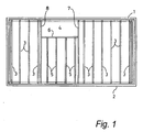
- a domestic building (such as a house of block of flats) has opposed side walls 1 and 2 spanned by conventional joists 3.
- the joist ends are attached to the walls 1 and 2 either by conventional joist hangers or by the ends of the joists being built into the walls, in conventional fashion.
- the building has a rectangular stairwell 4 to accommodate a staircase, the stairwell 4 having a length parallel to the wall 1 of 2400mm and width perpendicular to the wall 1 of 1000mm. It can be seen that over the length of the stairwell there are four joists 5 shorter in length than the normal length joists 3 spanning the walls 1 and 2.
- the ends of these shorter joists 5 are connected (e.g. by conventional joist hangers) to a transverse joist 6 defining the stairwell edge parallel to the wall 1.
- the ends of this transverse joist 6 are in turn connected (e.g. by conventional joist hangers) to the pair of respective joists 7 and 8 defining the ends of the stairwell space.
- This pair of joists 7 and 8 must therefore be designed to withstand greater bending moments than the remaining joists, because part of the loading applied to the floor laid over the shorter joists 5 will be transmitted to the pair of joists 7 and 8 through the intermediary of the transverse joist 6.
- a pair of conventional joists (like the joists 3) have sometimes been placed side by side and screwed together to form a composite joist to serve as each of the joists 7 and 8.
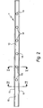
- the invention provides a joist of special design to serve as each of the joists 7 and 8 and Figures 2 to 5 show one such joist 7.
- the joist 7 comprises a galvanised steel channel member folded from 11 ⁇ 2mm sheet steel so as to have a central vertical web 10 with a height dimension of 218mm and two horizontal flanges 11 and 12 with a width dimension of 72mm from the extremities of which project two out-turned vertical lips 13 and 14 with a height dimension of 15mm.
- a strip of timber 15 of rectangular section (72mm wide x 35mm deep) is attached by a polyurethane adhesive to the whole of the upper surface of the upper flange and also to the adjacent surface of the upturned lip 13.
- the strip of timber 15 has a width corresponding to the width of the flange 11 and forms an upper chord of the joist.
- a second and identical timber strip 16 of rectangular section (72mm wide x 35mm deep) is attached by the same adhesive to the whole of the lower surface of the lower flange 12 and also to the adjacent surface of the down-turned lip 14.
- the timber strip 16 has a width corresponding to the width of the lower flange 12 and forms a lower chord of the joist.
- the adhesive is sufficiently strong to bond the wood to the steel so that the shear forces on this interface are resisted, imparting substantial stiffness to the composite joist.
- a series of six circular holes 18 of 80mm diameter are formed in the web 10, the holes 18 being at a regular spacing of 600mm, this distance also being the distance between an end of the joist (the right hand end in Figure 2) and the nearest hole 18.
- the other end of the joist has a length 19 of 1200mm devoid of holes.
- Each hole 18 has a lip 20 which is curved in section as best seen in Figure 5, the lip 20 projecting 10mm from the web 10 on the same side thereof as the upper and lower flanges 11,12.
- the holes 18 allow for the passage through the joist of cables, pipes or ducting which can be passed through the holes 18 without the risk of snagging on the edges of the holes as a result of the provision of the lips 20.
- the holes 18 are centred on the neutral axis of the joist so as to minimise loss of stiffness or resistance to bending.
- the joist 7 spans the walls 1 and 2 in a position defining one end of the stairwell 4, as shown in Figure 1.
- the ends of the joist 7 are supported on the walls 1 and 2 either by joist hangers or by the ends of the joists being built into the walls 1 and 2. In either event, the ends of the joist 7 can be trimmed on site, it being understood that the length 19 of the joist which is devoid of holes is positioned so as to define the edge of the stairwell space and that the flat side of the joist (the right-hand side in Figure 4) faces towards the stairwell 4.
- joist lengths may vary from 3600mm to 5400mm in steps of 600mm, each joist having a length at one end devoid of holes and being trimmable at each end to suit the floor being constructed.
Landscapes
- Engineering & Computer Science (AREA)
- Architecture (AREA)
- Civil Engineering (AREA)
- Structural Engineering (AREA)
- Chemical & Material Sciences (AREA)
- Composite Materials (AREA)
- Life Sciences & Earth Sciences (AREA)
- Wood Science & Technology (AREA)
- Physics & Mathematics (AREA)
- Electromagnetism (AREA)
- Floor Finish (AREA)
- Rod-Shaped Construction Members (AREA)
Applications Claiming Priority (1)
| Application Number | Priority Date | Filing Date | Title |
|---|---|---|---|
| GB0605819A GB2436335B (en) | 2006-03-23 | 2006-03-23 | Joists |
Publications (2)
| Publication Number | Publication Date |
|---|---|
| EP1837451A2 true EP1837451A2 (de) | 2007-09-26 |
| EP1837451A3 EP1837451A3 (de) | 2008-06-04 |
Family
ID=36384023
Family Applications (1)
| Application Number | Title | Priority Date | Filing Date |
|---|---|---|---|
| EP07250686A Withdrawn EP1837451A3 (de) | 2006-03-23 | 2007-02-20 | Balken |
Country Status (3)
| Country | Link |
|---|---|
| EP (1) | EP1837451A3 (de) |
| GB (1) | GB2436335B (de) |
| ZA (1) | ZA200701806B (de) |
Cited By (6)
| Publication number | Priority date | Publication date | Assignee | Title |
|---|---|---|---|---|
| WO2020165362A1 (fr) * | 2019-02-15 | 2020-08-20 | Goahead Sprl | Pièce de couplage et ensemble de constructions préfabriquées comportant la pièce de couplage |
| WO2020171756A1 (en) * | 2019-02-18 | 2020-08-27 | Patrick Johansson | Building stud, wall structure comprising such a building stud and a method for forming a wall structure |
| SE543391C2 (sv) * | 2019-02-18 | 2020-12-29 | Atricon Ab | Byggregel, väggkonstruktion innefattande en sådan byggregel samt förfarande för att bilda en väggkonstruktion |
| CN112770989A (zh) * | 2018-09-18 | 2021-05-07 | 艾勒技术公司 | 混合式智能复合集装箱和操作该集装箱的方法 |
| CN115667643A (zh) * | 2020-06-01 | 2023-01-31 | 阿特瑞康股份公司 | 建筑立柱、包括该建筑立柱的墙壁结构和用于形成墙壁结构的方法 |
| SE2230047A1 (en) * | 2022-02-18 | 2023-08-19 | Atricon Ab | Building stud and related method |
Families Citing this family (2)
| Publication number | Priority date | Publication date | Assignee | Title |
|---|---|---|---|---|
| DE102018204201A1 (de) * | 2018-03-20 | 2019-09-26 | Peri Gmbh | Schalungsträger mit einem durch ein Innenfachwerk ausgesteiften Hohlprofilsteg als Gurtverbinder |
| AU2023473814A1 (en) * | 2023-11-20 | 2025-09-25 | Sekisui House, Ltd. | Floor structure |
Citations (1)
| Publication number | Priority date | Publication date | Assignee | Title |
|---|---|---|---|---|
| US20020166306A1 (en) | 2001-05-09 | 2002-11-14 | Stuart Wilson | Structural beam |
Family Cites Families (7)
| Publication number | Priority date | Publication date | Assignee | Title |
|---|---|---|---|---|
| US4034957A (en) * | 1976-02-17 | 1977-07-12 | Symons Corporation | Concrete formwork including I-beam support |
| SE429667B (sv) * | 1979-06-18 | 1983-09-19 | Nielsen Hilmer R | Byggelement samt prefabricerad sektion uppbyggd av dessa element |
| US4862667A (en) * | 1987-09-18 | 1989-09-05 | Melland Robert C | Metal structural fastener/stiffener with integral prongs |
| AU650614B2 (en) * | 1988-05-04 | 1994-06-30 | Tecbeam Pty Ltd | Composite building element |
| CA2077170A1 (en) * | 1992-08-28 | 1994-03-01 | Warren Eberschlag | Lightweight metal construction framing components |
| CA2494821C (en) * | 2002-08-05 | 2014-10-14 | Jeffrey A. Anderson | Metal framing member and method of manufacture |
| JP2006257853A (ja) * | 2005-03-18 | 2006-09-28 | Hokkaido | 薄鋼板と木材の複合梁 |
-
2006
- 2006-03-23 GB GB0605819A patent/GB2436335B/en not_active Expired - Fee Related
-
2007
- 2007-02-20 EP EP07250686A patent/EP1837451A3/de not_active Withdrawn
- 2007-02-28 ZA ZA200701806A patent/ZA200701806B/en unknown
Patent Citations (1)
| Publication number | Priority date | Publication date | Assignee | Title |
|---|---|---|---|---|
| US20020166306A1 (en) | 2001-05-09 | 2002-11-14 | Stuart Wilson | Structural beam |
Cited By (14)
| Publication number | Priority date | Publication date | Assignee | Title |
|---|---|---|---|---|
| CN112770989A (zh) * | 2018-09-18 | 2021-05-07 | 艾勒技术公司 | 混合式智能复合集装箱和操作该集装箱的方法 |
| CN112770989B (zh) * | 2018-09-18 | 2022-10-28 | 艾勒技术公司 | 混合式智能复合集装箱和操作该集装箱的方法 |
| BE1027053B1 (fr) * | 2019-02-15 | 2020-09-14 | Goahead Sprl | Pièce de couplage et ensemble de constructions préfabriquées comportant la pièce de couplage |
| WO2020165362A1 (fr) * | 2019-02-15 | 2020-08-20 | Goahead Sprl | Pièce de couplage et ensemble de constructions préfabriquées comportant la pièce de couplage |
| AU2020224564B2 (en) * | 2019-02-18 | 2022-10-20 | Atricon Ab | Building stud, wall structure comprising such a building stud and a method for forming a wall structure |
| CN113646493A (zh) * | 2019-02-18 | 2021-11-12 | 阿特瑞康股份公司 | 建筑壁骨、包括这种建筑壁骨的墙壁结构和用于形成墙壁结构的方法 |
| SE543391C2 (sv) * | 2019-02-18 | 2020-12-29 | Atricon Ab | Byggregel, väggkonstruktion innefattande en sådan byggregel samt förfarande för att bilda en väggkonstruktion |
| WO2020171756A1 (en) * | 2019-02-18 | 2020-08-27 | Patrick Johansson | Building stud, wall structure comprising such a building stud and a method for forming a wall structure |
| US11814844B2 (en) | 2019-02-18 | 2023-11-14 | Atricon Ab | Building stud, wall structure comprising such a building stud and a method for forming a wall structure |
| CN115667643A (zh) * | 2020-06-01 | 2023-01-31 | 阿特瑞康股份公司 | 建筑立柱、包括该建筑立柱的墙壁结构和用于形成墙壁结构的方法 |
| US12428835B2 (en) | 2020-06-01 | 2025-09-30 | Atricon Ab | Building stud, wall structure comprising such a building stud and a method for forming a wall structure |
| SE2230047A1 (en) * | 2022-02-18 | 2023-08-19 | Atricon Ab | Building stud and related method |
| WO2023158353A1 (en) * | 2022-02-18 | 2023-08-24 | Atricon Ab | Foldable building stud from retracted storage position to an expanded mounting position, and related method therefor |
| SE545883C2 (en) * | 2022-02-18 | 2024-03-05 | Atricon Ab | Building stud comprising flange members and an interconnecting web member and related method |
Also Published As
| Publication number | Publication date |
|---|---|
| GB2436335B (en) | 2008-08-06 |
| ZA200701806B (en) | 2010-05-26 |
| GB2436335A (en) | 2007-09-26 |
| GB0605819D0 (en) | 2006-05-03 |
| EP1837451A3 (de) | 2008-06-04 |
Similar Documents
| Publication | Publication Date | Title |
|---|---|---|
| EP1837451A2 (de) | Balken | |
| CA2121965C (en) | Composite structural steel wall reinforced with concrete and mold therefor | |
| US20220213684A1 (en) | Modular composite action panel and structural systems using same | |
| US6571527B1 (en) | Elongate structural member comprising a zigzag web and two chords wherein one chord comprises a channel with inwardly directed lips on the channel ends | |
| CA2491194A1 (en) | Floor system with steel joists having openings with edge reinforcements and method | |
| US20140338282A1 (en) | Modular joist brace bracket | |
| US4361999A (en) | Self-supporting transverse partition wall support | |
| US20090120028A1 (en) | Insulating panel and method for building and insulating walls and ceilings | |
| US5544459A (en) | Duct chase frame for joists | |
| EP1443156A1 (de) | Struktur aus Hauptprofilen und dazu quer liegende Hilfsprofile | |
| US2945328A (en) | Floor joist and assembly | |
| EP0110849A1 (de) | Eine Oberfläche bildende Platte | |
| US2090632A (en) | Wall support | |
| GB2220217A (en) | Ceilings | |
| US20060000182A1 (en) | Wall stud assembly for modular walls | |
| GB2340141A (en) | Cold rolled steel joist | |
| EP2261434B1 (de) | Dachsparren | |
| WO2006052603A2 (en) | Modular building system and componentry | |
| AU2009100419A4 (en) | Open web lateral load distributing joist assembly | |
| GB2341400A (en) | Mounting plasterboard panels | |
| AU2008100096A4 (en) | Concrete Beam for Composite Suspended Concrete Floor System | |
| NO20092929A1 (no) | Trehulldekket | |
| EP3211148A1 (de) | Bodenteil für einen isolationsboden | |
| AU2018100227A4 (en) | Improvements in Joists | |
| WO2006077484A1 (en) | Flooring system with concrete slabs supported by trusses |
Legal Events
| Date | Code | Title | Description |
|---|---|---|---|
| PUAI | Public reference made under article 153(3) epc to a published international application that has entered the european phase |
Free format text: ORIGINAL CODE: 0009012 |
|
| AK | Designated contracting states |
Kind code of ref document: A2 Designated state(s): AT BE BG CH CY CZ DE DK EE ES FI FR GB GR HU IE IS IT LI LT LU LV MC NL PL PT RO SE SI SK TR |
|
| AX | Request for extension of the european patent |
Extension state: AL BA HR MK YU |
|
| PUAL | Search report despatched |
Free format text: ORIGINAL CODE: 0009013 |
|
| AK | Designated contracting states |
Kind code of ref document: A3 Designated state(s): AT BE BG CH CY CZ DE DK EE ES FI FR GB GR HU IE IS IT LI LT LU LV MC NL PL PT RO SE SI SK TR |
|
| AX | Request for extension of the european patent |
Extension state: AL BA HR MK RS |
|
| 17P | Request for examination filed |
Effective date: 20080910 |
|
| 17Q | First examination report despatched |
Effective date: 20081023 |
|
| AKX | Designation fees paid |
Designated state(s): AT BE BG CH CY CZ DE DK EE ES FI FR GB GR HU IE IS IT LI LT LU LV MC NL PL PT RO SE SI SK TR |
|
| STAA | Information on the status of an ep patent application or granted ep patent |
Free format text: STATUS: THE APPLICATION IS DEEMED TO BE WITHDRAWN |
|
| 18D | Application deemed to be withdrawn |
Effective date: 20110901 |