EP1836764B1 - Stromversorgungsvorrichtung für einen elektromotor, verfahren zum betreiben eines elektromotors - Google Patents
Stromversorgungsvorrichtung für einen elektromotor, verfahren zum betreiben eines elektromotors Download PDFInfo
- Publication number
- EP1836764B1 EP1836764B1 EP05850155A EP05850155A EP1836764B1 EP 1836764 B1 EP1836764 B1 EP 1836764B1 EP 05850155 A EP05850155 A EP 05850155A EP 05850155 A EP05850155 A EP 05850155A EP 1836764 B1 EP1836764 B1 EP 1836764B1
- Authority
- EP
- European Patent Office
- Prior art keywords
- electric motor
- motor
- motor vehicle
- emergency
- safety position
- Prior art date
- Legal status (The legal status is an assumption and is not a legal conclusion. Google has not performed a legal analysis and makes no representation as to the accuracy of the status listed.)
- Expired - Lifetime
Links
Images

Classifications
-
- H—ELECTRICITY
- H02—GENERATION; CONVERSION OR DISTRIBUTION OF ELECTRIC POWER
- H02P—CONTROL OR REGULATION OF ELECTRIC MOTORS, ELECTRIC GENERATORS OR DYNAMO-ELECTRIC CONVERTERS; CONTROLLING TRANSFORMERS, REACTORS OR CHOKE COILS
- H02P3/00—Arrangements for stopping or slowing electric motors, generators, or dynamo-electric converters
- H02P3/06—Arrangements for stopping or slowing electric motors, generators, or dynamo-electric converters for stopping or slowing an individual dynamo-electric motor or dynamo-electric converter
- H02P3/18—Arrangements for stopping or slowing electric motors, generators, or dynamo-electric converters for stopping or slowing an individual dynamo-electric motor or dynamo-electric converter for stopping or slowing an AC motor
- H02P3/24—Arrangements for stopping or slowing electric motors, generators, or dynamo-electric converters for stopping or slowing an individual dynamo-electric motor or dynamo-electric converter for stopping or slowing an AC motor by applying DC to the motor
-
- H—ELECTRICITY
- H02—GENERATION; CONVERSION OR DISTRIBUTION OF ELECTRIC POWER
- H02P—CONTROL OR REGULATION OF ELECTRIC MOTORS, ELECTRIC GENERATORS OR DYNAMO-ELECTRIC CONVERTERS; CONTROLLING TRANSFORMERS, REACTORS OR CHOKE COILS
- H02P3/00—Arrangements for stopping or slowing electric motors, generators, or dynamo-electric converters
Definitions
- the invention relates to a power supply device for a run in a normal operation and / or in an emergency operation electric motor, in particular for an actuator in a motor vehicle, and a method for operating an electric motor in a normal operation and / or emergency operation, in particular for an actuator in a motor vehicle.
- a three-phase asynchronous motor is an electric motor that is operated with three-phase current. Seen electrically, an asynchronous motor is a short-circuited three-phase transformer whose secondary winding (a rotor) is rotatably mounted. By an operating voltage applied to a stator winding, a rotating magnetic field is generated inside the machine, which induces a current in the short-circuited inner winding (armature). This current itself builds up a magnetic field around the rotor. Both magnetic fields interact in such a way that ultimately a torque is generated.
- a three-phase synchronous motor is an electric motor, which is also operated with three-phase current. He has outside a winding that generates a magnetic rotating field.
- the rotor carries either permanent magnets or a field winding for field generation.
- the rotor with the excitation hurries in the synchronous motor to the rotating field.
- the synchronous machine has no slip, in contrast to the three-phase asynchronous motor, since no voltages must be induced in the rotor. Therefore, you can rely on their operation at the rigid network to their constant speed.
- the electric motors are usually controlled electronically using electronic control devices, wherein operating states (system states) of the controlled by means of the electric motor to be controlled and / or the actuator to be adjusted system are monitored. If the monitored operating conditions are within certain specifiable limits, the monitored system operates in a state which is usually referred to as the normal state.
- system states operating states of the controlled by means of the electric motor to be controlled and / or the actuator to be adjusted system are monitored. If the monitored operating conditions are within certain specifiable limits, the monitored system operates in a state which is usually referred to as the normal state.
- control device generally provides a control for emergency or emergency operation in order to avoid damage to the controlled system ,
- Such an emergency operation may be, for example, an adjustment of the adjustable by the actuator component in a safety position, also referred to as fail-safe position.
- a safety position also referred to as fail-safe position.
- Known here is, for example, an electronic camshaft adjustment in a motor vehicle internal combustion engine, in which the electric motor of the actuator is disconnected from a controller in an error and the electric motor, the camshaft - if possible with a target target speed - adjusted so in the fail-safe position that the internal combustion engine can be operated at least still with emergency running properties.
- the approach of the fail-safe position or the adjustment in the fail-safe position can be effected for example by a return spring on the actuator.
- the disadvantage of this is that the return spring leads to an oversizing of the adjustment.
- Another disadvantage is that in normal operation, the (electric) motor has to overcome the spring force, which leads to a higher load during normal operation and / or higher drive costs of the adjustment.
- the approach of the fail-safe position can be further effected for example by a second parallel (electric) motor.
- a second parallel (electric) motor is associated with a high technical overhead and / or considerable additional costs.
- the fail-safe position can also be effected, for example, by short-circuiting the (electric) motor, which causes the motor to brake.
- the braking principle is based on an induced reverse voltage of the motor and is therefore speed-dependent. At lower speeds no braking torque is available, which keeps the adjustment system in the fail-safe position, if this is achieved.
- the object is achieved by the method according to claim 1.
- units and / or devices designated as such may be implemented both as physical units and / or devices and as purely functional, virtual units and / or devices, or both in hardware and in software.
- the power supply unit of the electric motor in particular a three-phase motor, such as a three-phase asynchronous motor or a three-phase synchronous motor, may preferably be set up such that a stator of the electric motor can be supplied with three-phase current in normal operation.
- the emergency running power supply device of the electric motor can furthermore preferably be set up in such a way that the stator, in particular at least two or three phases of the stator, is supplied with direct current in emergency operation, wherein the stator supplied with direct current during emergency operation then has a non-rotating and / or stationary magnetic field in emergency operation can train.
- the non-rotating and / or stationary magnetic field generated by the stator by means of the applied direct current particularly preferably generates a braking torque in the electric motor which decelerates the electric motor, in particular a rotor of the electric motor, rotational speed independently and / or to a standstill.
- a motor vehicle actuator When the electric motor is being decelerated, a motor vehicle actuator is particularly preferably moved to a safety position, in particular an emergency running position or a fail-safe position.
- the braking torque and thereby the travel or adjustment speed is thus directly dependent on the current flowing in the phases.
- the motor vehicle actuator is held in the safety position by the non-rotating and / or stationary magnetic field and / or by the braking torque generated thereby. Maintaining the safety position over time is expedient to ensure with a minimum power consumption, in order to minimize the energy consumption, to optimally adjust the braking torque and to protect the electric motor against overtemperature.
- the current consumption ie the direct current and / or thus the braking torque, with which the electric motor can be braked is, and / or a travel speed when moving the motor vehicle actuator into the safety position, is adjustable.
- At least one or more relays and / or one or more limiting resistors can be provided.
- at least one or more transistors in particular controllable transistors, such as FETs or low-side FETs, can be provided.
- the transistors can be driven pulse-width modulated (PWM) at 20 kHz.
- controllable transistor (s) also to be or are used in a normal mode in a power output stage, in particular in the case of the electric motor and / or the motor vehicle actuator.
- the power supply unit has an AC power source or a DC power source, in particular a battery, such as a motor vehicle battery, in particular for a motor vehicle onboard supply, with a power output stage, in particular an open DC-AC power amplifier, for example an inverter.
- a battery such as a motor vehicle battery
- a power output stage in particular an open DC-AC power amplifier, for example an inverter.
- the electric motor is a three-phase motor, such as an asynchronous motor or a synchronous motor, in particular for a motor vehicle actuator, such as a parallel shift transmission (PSG) or a camshaft adjuster.
- a motor vehicle actuator such as a parallel shift transmission (PSG) or a camshaft adjuster.
- the emergency power supply unit also has a direct current source, in particular a battery, such as a motor vehicle battery, in particular for a motor vehicle onboard supply.
- a direct current source in particular a battery, such as a motor vehicle battery, in particular for a motor vehicle onboard supply.
- the power supply unit and the emergency power supply unit are the same. Use DC power source.
- the apparatus may particularly preferably have a switching unit which, in particular in the case of a predefinable system state of a complete system comprising the electric motor, such as, for example, the parallel shift transmission (PSG) or the camshaft adjusting system with the motor vehicle actuator, switches from normal-running operation to emergency operation mode. in particular by shorting the Electric motor, in particular the entire system is brought into a safety state.
- a switching unit which, in particular in the case of a predefinable system state of a complete system comprising the electric motor, such as, for example, the parallel shift transmission (PSG) or the camshaft adjusting system with the motor vehicle actuator, switches from normal-running operation to emergency operation mode. in particular by shorting the Electric motor, in particular the entire system is brought into a safety state.
- the device may have a condition monitoring device which monitors the system states and / or detects a predefinable system state, in particular an error state.
- the device or its developments can or can be particularly preferably used for a method of a motor vehicle actuator in a safety position and / or to hold a motor vehicle actuator in a safety position (emergency operation concept).
- the motor vehicle actuator When the electric motor is being decelerated, the motor vehicle actuator is moved to the safety position, the fail-safe position, or the motor vehicle actuator is held in the safety position by the braking torque in the electric motor.
- the electric motor of a motor vehicle actuator is used as a DC brake in emergency or in fail-safe positions.
- a predefinable situation of an overall system which can be adjusted by the motor vehicle actuator is detected and the electric motor is switched from normal-running operation to emergency operation in the case of a recognized predefinable situation.
- Fig.1 is a first embodiment, a braking method or emergency concept with relays for electric motors for motor vehicle actuators in normal or emergency mode, illustrates.
- Fig.1 shows a circuit 100 for an electric motor in a motor vehicle actuator for a normal and for an emergency operation, for example, for an electronic camshaft adjustment.
- Fig.1 shows, in normal operation 101, a three-phase motor 110, in this case an asynchronous motor 110, by means of a battery 120, such as a motor vehicle on-board battery 120, and a (power) output stage 130, in this case an open DC-AC stage 130, with Three-phase powered.
- Fig.1 shows the corresponding interconnection of the phases 131, 132, 133 of the asynchronous motor 110 for the normal operation 101st
- This circuit 100 further provides an emergency operation 102 with appropriate interconnection, in which when an error occurs the asynchronous motor 110 is disconnected from a controller (not shown) and the motor vehicle actuator is moved into a fail-safe position.
- the circuit 100 provides a short circuit 150, by which the power output stage 130 is short-circuited at the error occurred.
- Fig.1 1 shows here the short-circuiting circuit 150 on two phases 131, 132 of the asynchronous motor 110, wherein this can also be switched to three phases of the asynchronous motor 110.
- This short circuit 150 has two strands in this case 151, 152, which each have a switchable relay 160, 161 and a predetermined limiting resistor 170, 171.
- the stator of the asynchronous motor 110 in emergency mode
- the on-board voltage 120 with direct current which in Fig.1 is illustrated by ldc brake or braking current 180 supplied, wherein it generates a non-rotating magnetic field.
- This standing magnetic field brakes the rotating rotor of the asynchronous motor 110 to a standstill and holds the motor vehicle actuator in the fail-safe position.
- the braking torque and thereby the adjustment speed (also braking time) are dependent on the current flowing in the phases.
- Fig.2 is a second embodiment, a braking method or emergency concept with FETs for electric motors for motor vehicle actuators in normal or emergency mode, illustrates.
- Fig.2 1 shows a circuit 200 corresponding in function to the circuit 100 for the asynchronous motor 110 in the motor vehicle actuator for the normal-running 101 and for the emergency operation 102, in which the current consumption via controllable transistors 210, in this case low-side FETs 210, which can be derived from the power output stage that is used in normal operation, is adjustable.
- circuit 200 corresponds to the circuit 100.
- PWM pulse-width modulated
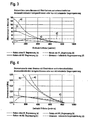
- Fig.3 and Fig.4 show brake currents ( Figure 3 ) and braking torques ( Figure 4 ) or corresponding courses or curves in each case depending on the engine speed for the emergency concept with relay without limiting resistor (curve a)), for the emergency concept with relay with small limiting resistor (curve b)) and for the emergency concept with relay with large limiting resistor ( Curve c)) (see circuit Fig.1 ) and for the (speed-dependent) emergency running concept based on an induced counter-voltage of the motor (curve d)).
Landscapes
- Engineering & Computer Science (AREA)
- Power Engineering (AREA)
- Output Control And Ontrol Of Special Type Engine (AREA)
- Valve Device For Special Equipments (AREA)
- Control Of Motors That Do Not Use Commutators (AREA)
Abstract
Description
- Die Erfindung betrifft eine Stromversorgungsvorrichtung für einen in einem Normallaufbetrieb und/oder in einem Notlaufbetrieb betreibbaren Elektromotor, insbesondere für einen Stellantrieb in einem Kraftfahrzeug, sowie ein Verfahren zum Betreiben eines Elektromotors in einem Normallaufbetrieb und/oder Notlaufbetrieb, insbesondere für einen Stellantrieb in einemraftfahrzeug.
- Die DE 10257706 beschreibt einen von einem Elektromotor angetriebenen Nockenwellenversteller.
- Es ist bekannt, verstellbare Bauteile in einem Kraftfahrzeug mittels eines Stellantriebs in ihrer Lage zu verstellen, um dadurch Systeme im Kraftfahrzeug zu steuern bzw. Systemzustände, insbesondere gezielt, zu beeinflussen und/oder herbeizuführen, wie beispielsweise bei einer Nockenwelle bzw. einem Nockenwellenversteller für einen Kraftfahrzeug-Verbrennungsmotor oder ein Ventil bzw. einer Ventilverstellung für eine Kraftstoffeinspritzung. Derartige Kraftfahrzeug-Stellantriebe bewirken, wie weiter bekannt ist, die Verstellung der Bauteile mittels Elektromotoren (Stellmotoren), beispielsweise mittels bekannter Drehstrommotoren, wie Drehstrom-Synchron- oder -Asynchronmotoren.
- Ein Drehstrom-Asynchronmotor, kurz im folgenden Asynchronmotor, ist ein Elektromotor, der mit Drehstrom betrieben wird. Elektrisch gesehen ist ein Asynchronmotor ein kurzgeschlossener Drehstrom-Transformator, dessen Sekundärwicklung (ein Rotor) drehbar gelagert ist. Durch eine an eine Statorwicklung angelegte Betriebsspannung wird im Inneren der Maschine ein magnetisches Drehfeld erzeugt, welches in der kurzgeschlossenen inneren Wicklung (Anker) einen Strom induziert. Dieser Strom baut selbst wiederum ein Magnetfeld um den Rotor auf. Beide Magnetfelder wechselwirken so, dass letztlich ein Drehmoment erzeugt wird.
- Ein Drehstrom-Synchronmotor, kurz im folgenden Synchronmotor, ist ein Elektromotor, der ebenfalls mit Drehstrom betrieben wird. Er besitzt außen eine Wicklung, die ein magnetisches Drehfeld erzeugt. Der Rotor trägt entweder Permanentmagneten oder eine Erregerwicklung zur Felderzeugung. Der Rotor mit der Erregung eilt bei dem Synchronmotor dem Drehfeld nach. Die Synchronmaschine hat im Unterschied zum Drehstrom-Asynchronmotor keinen Schlupf, da keine Spannungen in den Rotor induziert werden müssen. Daher kann man sich bei Betrieb am starren Netz auf ihre konstante Drehzahl verlassen.
- Bei modernen Stellantrieben werden die Elektromotoren meist unter Verwendung elektronischer Steuervorrichtungen elektronisch angesteuert, wobei Betriebszustände (Systemzustände) des mittels des zu steuernden Elektromotors und/oder des zu verstellenden Stellantriebs gesteuerten Systems überwacht werden. Bewegen sich die überwachten Betriebszuständen innerhalb bestimmter, vorgebbarer Grenzen, arbeitet das überwachte System in einem meist als Normalzustand bezeichneten Zustand.
- Werden allerdings sich außerhalb der Grenzen der normalen Betriebszuständen befindliche Betriebszustände, beispielsweise als Systemfehler bezeichenbar, festgestellt - kurz werden Systemfehler festgestellt - , so sieht die Steuervorrichtung in der Regel eine Steuerung für einen Not- bzw. Notlaufbetrieb vor, um Schädigungen des gesteuerten Systems zu vermeiden.
- Ein solcher Notbetrieb kann beispielsweise ein Verstellen des durch den Stellantrieb verstellbaren Bauteils in eine Sicherheitsposition, auch als Fail-Safe-Position bezeichnet, sein. Bekannt ist hier beispielsweise eine elektronische Nockenwellenverstellung bei einem Kraftfahrzeugverbrennungsmotor, bei der bei einem Fehler der Elektromotor des Stellantriebs von einem Controller getrennt wird und der Elektromotor die Nockenwelle noch - nach Möglichkeit mit einer einzuhaltenden Zielverstellgeschwindigkeit - derart in die Fail-Safe-Position verstellt, dass der Verbrennungsmotor zumindest noch mit Notlaufeigenschaften betrieben werden kann.
- Das Anfahren der Fail-Safe-Position bzw. das Verstellen in die Fail-Safe-Position kann beispielsweise durch eine Rückstellfeder am Stellantrieb bewirkt werden. Nachteilig daran ist, dass die Rückstellfeder zu einer Überdimensionierung des Verstellsystems führt. Weiter nachteilig ist daran, dass im Normalbetrieb der (Elektro-)Motor die Federkraft überwinden muss, was zu einer höheren Last im Normalbetrieb und/oder zu höheren Antriebskosten des Verstellsystems führt.
- Das Anfahren der Fail-Safe-Position kann weiter beispielsweise durch einen zweiten parallel geschalteten (Elektro-)Motor bewirkt werden. Dies ist allerdings mit einen hohen technischen Mehraufwand und/oder erheblichen Mehrkosten verbunden.
- Die Fail-Safe-Position kann weiterhin beispielsweise durch ein Kurzschließen des (Elektro)-Motors, welches ein Abbremsen des Motors bewirkt, bewirkt werden. Das Bremsprinzip basiert auf einer induzierten Gegenspannung des Motors und ist deswegen drehzahlabhängig. Bei kleineren Drehzahlen ist kein Bremsmoment mehr vorhanden, welches das Verstellsystem in der Fail-Safe-Position hält, falls diese überhaupt erreicht wird.
- Es ist Aufgabe der vorliegenden Erfindung, einen Betrieb eines Elektromotors zu realisieren, bei dem ein Notlaufkonzept bzw. ein Erreichen einer Fail-Safe-Position einfach, sicher und kostengünstig zu erreichen ist.
- Die Aufgabe wird durch das Verfahren nach Anspruch 1 gelöst.
- Vorteilhafte Ausführungsformen und Weiterbildungen sind Gegenstand der Unteransprüche. Die Gegenstände der Unteransprüche beziehen sich auf das erfindungsgemäße Verfahren zum Betreiben des Elektromotors in dem Normallauf- und/oder in dem Notlaufbetrieb.
- Anzumerken ist, dass als solche bezeichneten Einheiten und/oder Vorrichtungen sowohl als physikalische Einheiten und/oder Vorrichtungen als auch als rein funktional, virtuelle Einheiten und/oder Vorrichtungen bzw. sowohl in Hard- als auch in Software realisiert sein können.
- Die Stromversorgungseinheit des Elektromotors, insbesondere eines Drehstrommotors, wie eines Drehstrom-Asynchronmotors oder eines Drehstrom-Synchronmotors, kann bevorzugt derart eingerichtet sein, dass ein Stator des Elektromotors im Normallaufbetrieb mit Drehstrom versorgbar ist.
- Die Notlaufstromversorgungseinrichtung des Elektromotors kann weiterhin bevorzugt derart eingerichtet sein, dass der Stator, insbesondere zumindest zwei oder drei Phasen des Stators, im Notlaufbetrieb mit Gleichstrom versorgt wird, wobei der im Notlaufbetrieb mit Gleichstrom versorgte Stator dann im Notlaufbetrieb ein nicht drehendes und/oder stehendes Magnetfeld ausbilden kann.
- Durch das vom Stator mittels anliegendem Gleichstrom erzeugte, nicht drehende und/oder stehende, Magnetfeld wird besonderes bevorzugt ein Bremsmoment im Elektromotor erzeugt, welches den Elektromotor, insbesondere einen Rotor des Elektromotors, Drehzahl unabhängig und/oder bis zu einem Stillstand abbremst.
- Besonders bevorzugt wird beim Abbremsen des Elektromotors ein Kraftfahrzeug-Stellantrieb in eine Sicherheitsposition, insbesondere eine Notlaufposition oder eine Fail-Safe-Position, verfahren. Das Bremsmoment und dadurch die Verfahr- bzw. Verstellgeschwindigkeit ist damit direkt von dem in den Phasen fließenden Strom abhängig.
- Weiter kann bevorzugt vorgesehen werden, dass durch das nicht drehende und/oder stehende Magnetfeld und/oder durch das dadurch erzeugte Bremsmoment der Kraftfahrzeug-Stellantrieb in der Sicherheitsposition gehalten wird. Das Halten der Sicherheitsposition über die Zeit ist zweckmäßig mit einer minimalen Stromaufnahme zu gewährleisten, um die Energieaufnahme zu minimieren, das Bremsmoment optimal einzustellen und den Elektromotor gegen Übertemperatur zu schützen.
- Dazu kann besonders bevorzugt vorgesehen werden, dass die Stromaufnahme, d.h. der Gleichstrom und/oder damit das Bremsmoment, mit welchem der Elektromotor abbremsbar ist, und/oder eine Verfahrgeschwindigkeit beim Verfahren des Kraftfahrzeug-Stellantriebs in die Sicherheitsposition, einstellbar ist.
- Dazu kann bzw. können mindestens ein oder mehrere Relais und/oder ein oder mehrere Begrenzungswiderstände vorgesehen sein. Auch kann bzw. können mindestens ein oder mehrere Transistoren, insbesondere steuerbare Transistoren, wie FETs oder Low-Side-FETs, vorgesehen sein. Beispielsweise können die Transistoren puls-weiten-moduliert (PWM) mit 20 kHz angesteuert werden.
- Hier kann weiter zweckmäßig vorgesehen sein, dass der bzw. die steuerbaren Transistoren auch bei einer Leistungsendstufe, insbesondere bei dem Elektromotor und/oder dem Kraftfahrzeug-Stellantrieb, im Normallaufbetrieb eingesetzt wird bzw. werden.
- Bevorzugt kann auch vorgesehen werden, dass die Stromversorgungseinheit eine Wechselstromquelle oder eine Gleichstromquelle, insbesondere eine Batterie, wie eine Kraftfahrzeugbatterie, insbesondere für eine Kraftfahrzeugbordversorgung, mit einer Leistungsendstufe, insbesondere einer offenen DC-AC-Endstufe, beispielsweise einem Wechselrichter, aufweist.
- Bei einer besonders bevorzugten Weiterbildung ist der Elektromotor ein Drehstrommotor, wie ein Asynchronmotor oder ein Synchronmotor, insbesondere für einen Kraftfahrzeug-Stellantrieb, wie einem Parallelschaltgetriebe (PSG) oder einem Nockenwellenversteller.
- Besonders bevorzugt kann weiterhin vorgesehen werden, dass auch die Notlaufstromversorgungseinheit eine Gleichstromquelle, insbesondere eine Batterie, wie eine Kraftfahrzeugbatterie, insbesondere für eine Kraftfahrzeugbordversorgung, aufweist. Insbesondere kann vorgesehen werden, dass Stromversorgungseinheit und Notiaufstromversorgüngseihheit dieselbe. Gleichstromquelle nutzen.
- Weiter kann besonders bevorzugt die Vorrichtung eine Schalteinheit aufweisen, welche, insbesondere bei einem vorgebbaren Systemzustand eines den Elektromotor aufweisenden technischen Gesamtsystems, wie hier beispielsweise das Parallelschaltgetriebe (PSG) oder das Nockenwellenverstellsystem mit dem Kraftfahrzeug-Stellantrieb, ein Umschalten vom Normallaufbetrieb in den Notlaufbetrieb bewirkt, insbesondere durch ein Kurzschließen des Elektromotors, wobei insbesondere das Gesamtsystem in einen Sicherheitszustand gebracht wird.
- Die Vorrichtung kann eine Zustandsüberwachungseinrichtung aufweisen, welche die Systemzustände überwacht und/oder einen vorgebbaren Systemzustand, insbesondere einen Fehlerzustand, erkennt.
- Die Vorrichtung oder deren Weiterbildungen kann bzw. können insbesondere besonders bevorzugt eingesetzt werden zu einem Verfahren eines Kraftfahrzeug-Stellantriebs in eine Sicherheitsposition und/oder zu einem Halten eines Kraftfahrzeug-Stellantriebs in einer Sicherheitsposition (Notlaufkonzept).
- Dabei wird im Notlaufbetrieb durch den Gleichstrom im Stator ein nichtdrehendes Magnetfeld erzeugt. Dadurch wird weiterhin ein, Drehzahl unabhängiges Bremsmoment im Elektromotor erzeugt, durch welches der Elektromotor bzw. der Rotor im Elektromotor bis zum Stillstand abgebremst wird.
- Beim Abbremsen des Elektromotors wird der Kraftfahrzeug-Stellantrieb in die Sicherheitsposition, der Fail-Safe-Position, verfahren bzw. durch das Bremsmoment im Elektromotor wird der Kraftfahrzeug-Stellantrieb in der Sicherheitsposition gehalten. Anschaulich gesehen wird hier der Elektromotor eines Kraftfahrzeugs-Stellantriebs als Gleichstrombremse im Notlauf oder in Fail-Safe-Positionen genutzt.
- Weiter kann hier auch vorgesehen werden, dass eine vorgebbare Situation eines durch den Kraftfahrzeug-Stellantrieb verstellbaren Gesamtsystems erkannt wird und der Elektromotor bei erkannter vorgebbarer Situation lurch Kurzschließen vom Normallaufbetrieb in den Notlaufbetrieb geschaltet wird.
- Im Folgenden sollen Ausführungsbeispiele der Vorrichtung anhand der Figuren erläutert werden. Es zeigt:
- Fig. 1
- ein erstes beispiethaftes Notlaufkonzept mit Relais für einen Kraftfahrzeug-Stellantrieb;
- Fig. 2
- ein zweites beispielhaftes Notlaufkonzept mit FETs für einen Kraftfahrzeug-Stellantrieb;
- Fig. 3
- ein Diagram mit Kurven, welche einen Zusammenhang zwischen einer Motordrehzahl und einem Motorstrom für verschiedene Notlaufkonzepte verdeutlichen;
- Fig. 4
- ein Diagram mit Kurven, welche einen Zusammenhang zwischen einer Motordrehzahl und einem Bremsmoment für verschiedene Notlaufkonzepte verdeutlichen.
- In
Fig.1 ist ein erstes Ausführungsbeispiel, ein Bremsverfahren bzw. Notlaufkonzept mit Relais für Elektromotoren für Kraftfahrzeug-Stellantriebe im Normal- oder Notlaufbetrieb, verdeutlicht.Fig.1 zeigt eine Schaltung 100 für einen Elektromotor bei einem Kraftfahrzeug-Stellantrieb für einen Normallauf- und für einen Notlaufbetrieb, beispielsweise für eine elektronische Nockenwellenverstellung. - Bei dieser Schaltung 100 wird, wie
Fig.1 zeigt, im Normallaufbetrieb 101 ein Drehstrommotor 110, in diesem Fall ein Asynchronmotor 110, mittels einer Batterie 120, beispielsweise einer Kraftfahrzeug-Bordbatterie 120, und einer (Leistungs-)Endstufe 130, in diesem Fall eine offene DC-AC-Stufe 130, mit Drehstrom gespeist.Fig.1 zeigt die entsprechende Verschaltung der Phasen 131, 132, 133 des Asynchronmotors 110 für den Normallaufbetrieb 101. - Diese Schaltung 100 sieht weiter einen Notlaufbetrieb 102 mit entsprechender Verschaltung vor, bei welchem bei einem aufgetretenen Fehler der Asynchronmotor 110 von einem Controller getrennt wird (nicht dargestellt) und der Kraftfahrzeug Stellantrieb in eine Fail-Safe-Position verfahren wird. Für den Notlaufbetrieb 102 bzw. die entsprechende Verschaltung sieht die Schaltung 100 eine Kurzschlussschaltung 150 vor, durch welche die Leistungsendstufe 130 bei dem aufgetretenen Fehler kurzgeschlossen wird.
-
Fig.1 zeigt hier die Kurzschlussschaltung 150 auf zwei Phasen 131, 132 des Asynchronmotors 110, wobei diese entsprechend auch auf drei Phasen des Asynchronmotors 110 geschaltet werden kann. Diese Kurzschlussschaltung 150 weist in diesem Fall zwei Leitungsstränge 151, 152 auf, welche jeweils ein zuschaltbares Relais 160, 161 sowie einen vorgebbaren Begrenzungswiderstand 170, 171 aufweisen. - Durch diese Kurzschlussschaltung 150 wird der Stator des Asynchronmotors 110 (im Notlaufbetrieb) durch die Bordspannung 120 mit Gleichstrom, welcher in
Fig.1 durch ldc-Bremse bzw. Bremsstrom 180 verdeutlicht ist, versorgt, wobei er ein nicht drehendes Magnetfeld erzeugt. Dieses stehende Magnetfeld bremst den drehenden Rotor des Asynchronmotors 110 bis zum Stillstand ab und hält den Kraftfahrzeug-Stellantrieb in der Fail-Safe-Position. Das Bremsmoment und dadurch die Verstellgeschwindigkeit (auch Bremszeit) sind dabei von dem in den Phasen fließenden Strom abhängig. - Das Halten der Fail-Safe-Position über die Zeit kann hier wegen der durch die Relais 160, 161 sowie durch die Begrenzungswiderstände 170, 171 einstellbaren Stromaufnahme mit einer minimalen Stromaufnahme gewährleistet werden, um die Energieaufnahme zu minimieren, das Bremsmoment optimal einzustellen und den Asynchronmotor 110 gegen Übertemperaturen zu schützen.
- In
Fig.2 ist ein zweites Ausführungsbeispiel, ein Bremsverfahren bzw. Notlaufkonzept mit FETs für Elektromotoren für Kraftfahrzeug-Stellantriebe im Normal- oder Notlaufbetrieb, verdeutlicht.Fig.2 zeigt eine in ihrer Funktion der Schaltung 100 entsprechende Schaltung 200 für den Asynchronmotor 110 bei dem Kraftfahrzeug-Stellantrieb für den Normallauf- 101 und für den Notlaufbetrieb 102, bei welcher die Stromaufnahme über steuerbare Transistoren 210, in diesem Fall Low-Side-FETs 210, die aus der Leistungsendstufe, die im Normallaufbetrieb eingesetzt wird, stammen können, einstellbar ist. - Die Ansteuerung der FETs 210 erfolgt puls-weiten-moduliert (PWM) hier beispielsweise mit 20 kHz und wirkt wie ein Endstufenschalter für die Endstufe 130.Im Übrigen entspricht Schaltung 200 der Schaltung 100.
-
Fig.3 und Fig.4 zeigen Bremsströme (Fig.3 ) und Bremsmomente (Fig.4 ) bzw. entsprechende Verläufe bzw. Kurven jeweils in Abhängigkeit von der Motordrehzahl für das Notlaufkonzept mit Relais ohne Begrenzungswiderstand (Kurve a)), für das Notlaufkonzept mit Relais mit kleinem Begrenzungswiderstand (Kurve b)) und für das Notlaufkonzept mit Relais mit großem Begrenzungswiderstand (Kurve c)) (vgl. SchaltungFig.1 ) sowie für das (drehzahlabhängige) Notlaufkonzept basierend auf einer induzierten Gegenspannung des Motors (Kurve d)). -
- 100
- Schaltung
- 101
- Normallaufbetrieb bzw. Normallaufbetriebsschaltung
- 102
- Notlaufbetrieb bzw. Notlaufbetriebsschaltung
- 110
- Asynchronmotor
- 120
- Batterie
- 130
- Leistungsendstufe
- 131, 132, 133
- Phasen des Asynchronmotors
- 150
- Kurzschlussschaltung
- 151, 152
- Leitungsstränge
- 160, 161
- Relais
- 170,171
- Begrenzungswiderstand, Bremswiderstand
- 180
- Idc-Bremse bzw. Bremsstrom
- 200
- Schaltung
- 210
- Low-Side-FETs
Claims (3)
- Verfahren zum Betreiben eines Elektromotors zum Verfahren eines Nockenwellenverstellsystems in eine Sicherheitsposition und zu einem Halten eines Nockenwellenverstellsystems in einer Sicherheitsposition, wobei eine vorgebbare Situation eines durch das Nockenwellenverstellsystems verstellbaren Gesamtsystems erkannt wird, wobei der Elektromotor bei erkannter vorgebbarer Situation durch Kurzschließen von einem Normallaufbetrieb (101) in einen Notlaufbetrieb (102) geschaltet wird, wobei in dem Notlaufbetrieb (102) ein Bremsmoment in dem Elektromotor erzeugt wird, welches den Elektromotor, insbesondere bis zum Stillstand abbremst, wobei beim Abbremsen der Kraftfahrzeug-Stellantrieb in die Sicherheitsposition verfahren wird, und/oder durch welches Bremsmoment der Kraftfahrzeug-Stellantrieb in der Sicherheitsposition gehalten wird.
- Verfahren nach Anspruch 1, dadurch gekennzeichnet, dass die Systemzustände des Gesamtsystems überwacht werden und/oder ein vorgebbarer Systemzustand, insbesondere ein Fehlerzustand, erkannt wird.
- Verfahren nach einem der voranstehenden Ansprüche, dadurch gekennzeichnet, dass der Gleichstrom und/oder das Bremsmoment, mit welchem der Elektromotor abgebremst wird, und/oder eine Verfahrgeschwindigkeit beim Verfahren des Kraftfahrzeug-Stellantriebs in die Sicherheitsposition eingestellt wird bzw. werden, insbesondere derart, dass eine Stromaufnahme und/oder eine Energieaufnahme des Elektromotors minimiert wird und/oder eine Überhitzung des Elektromotors verhindert wird.
Applications Claiming Priority (2)
| Application Number | Priority Date | Filing Date | Title |
|---|---|---|---|
| DE102005001575 | 2005-01-13 | ||
| PCT/DE2005/002260 WO2006074627A1 (de) | 2005-01-13 | 2005-12-15 | Stromversorgungsvorrichtung für einen elektromotor, verfahren zum betreiben eines elektromotors |
Publications (2)
| Publication Number | Publication Date |
|---|---|
| EP1836764A1 EP1836764A1 (de) | 2007-09-26 |
| EP1836764B1 true EP1836764B1 (de) | 2011-04-13 |
Family
ID=36282844
Family Applications (1)
| Application Number | Title | Priority Date | Filing Date |
|---|---|---|---|
| EP05850155A Expired - Lifetime EP1836764B1 (de) | 2005-01-13 | 2005-12-15 | Stromversorgungsvorrichtung für einen elektromotor, verfahren zum betreiben eines elektromotors |
Country Status (7)
| Country | Link |
|---|---|
| US (1) | US7781992B2 (de) |
| EP (1) | EP1836764B1 (de) |
| JP (1) | JP2008538492A (de) |
| KR (1) | KR101290888B1 (de) |
| CN (1) | CN101107774A (de) |
| DE (2) | DE112005003499A5 (de) |
| WO (1) | WO2006074627A1 (de) |
Cited By (1)
| Publication number | Priority date | Publication date | Assignee | Title |
|---|---|---|---|---|
| DE102017111949A1 (de) | 2017-05-31 | 2018-12-06 | Schaeffler Technologies AG & Co. KG | Elektromechanischer Nockenwellenversteller |
Families Citing this family (22)
| Publication number | Priority date | Publication date | Assignee | Title |
|---|---|---|---|---|
| AT500328B1 (de) * | 2002-02-07 | 2010-03-15 | Elin Ebg Traction Gmbh | Fahrzeug mit einem elektrischen antrieb und verfahren zum betrieb eines solchen fahrzeuges |
| WO2008141214A1 (en) * | 2007-05-09 | 2008-11-20 | Motor Excellence, Llc. | Electrical output generating devices and driven electrical devices with reduced flux leakage using permanent magnet components, and methods of making and using the same |
| US7989084B2 (en) | 2007-05-09 | 2011-08-02 | Motor Excellence, Llc | Powdered metal manufacturing method and devices |
| DE102008000146A1 (de) * | 2008-01-25 | 2009-07-30 | Zf Friedrichshafen Ag | Verfahren und Anordnung zum Ansteuern eines elektrischen Antriebes |
| US9662721B2 (en) | 2008-02-26 | 2017-05-30 | United Technologies Corporation | Method of generating a curved blade retention slot in a turbine disk |
| JP2012508549A (ja) | 2008-11-03 | 2012-04-05 | モーター エクセレンス, エルエルシー | 横方向および/またはコンミュテート式磁束システムの固定子の概念 |
| JP5246339B2 (ja) * | 2009-09-28 | 2013-07-24 | トヨタ自動車株式会社 | 車両用制御装置 |
| WO2011055230A2 (en) * | 2009-11-06 | 2011-05-12 | Inda S.R.L. | Electric drive and battery-charging power electronic system |
| JP4962583B2 (ja) * | 2010-03-11 | 2012-06-27 | 株式会社デンソー | 電力変換システムの放電制御装置 |
| WO2011115632A1 (en) | 2010-03-15 | 2011-09-22 | Motor Excellence Llc | Transverse and/or commutated flux systems configured to provide reduced flux leakage, hysteresis loss reduction, and phase matching |
| CN102959832B (zh) * | 2010-03-15 | 2016-11-16 | 电扭矩机器股份有限公司 | 具有相偏移的横向和/或换向通量系统 |
| WO2011115633A1 (en) | 2010-03-15 | 2011-09-22 | Motor Excellence Llc | Transverse and/or commutated flux system for electric bicycles |
| WO2012067896A2 (en) | 2010-11-17 | 2012-05-24 | Motor Excellence, Llc | Transverse and/or commutated flux systems having laminated and powdered metal portions |
| WO2012067895A2 (en) | 2010-11-17 | 2012-05-24 | Motor Excellence, Llc | Transverse and/or commutated flux system coil concepts |
| EP2641316B1 (de) | 2010-11-17 | 2019-02-13 | Motor Excellence, LLC | Quer- oder mischflusssysteme mit segmentierten statorlamellen |
| SI2737621T1 (sl) * | 2011-07-26 | 2022-10-28 | Moog Inc. | Vpenjalni sistem z električnim motorjem |
| DE102011087015B4 (de) * | 2011-11-24 | 2017-11-16 | Airbus Operations Gmbh | Energieversorgungssystem, Luft- oder Raumfahrzeug und Verfahren |
| DE102012103464A1 (de) * | 2012-04-19 | 2013-10-24 | Brose Fahrzeugteile Gmbh & Co. Kommanditgesellschaft, Hallstadt | Stellantrieb einer Luftdurchlassvorrichtung und Verfahren zur Steuerung eines Stellantriebs |
| KR101337859B1 (ko) * | 2012-07-02 | 2013-12-06 | 주식회사 만도 | 전자제어장치의 제어를 위한 모터 쇼트 검출 장치 및 방법 |
| DE102015225956A1 (de) * | 2015-12-18 | 2017-06-22 | Siemens Aktiengesellschaft | Vorrichtung und Verfahren zum Betreiben eines Triebfahrzeugs mit einer Wegrollsicherung und ein Triebfahrzeug mit einer solchen Wegrollsicherung |
| AT522121B1 (de) * | 2019-01-15 | 2021-04-15 | Avl List Gmbh | Verfahren zum Betreiben einer Antriebsvorrichtung, Antriebsvorrichtung sowie Kraftfahrzeug |
| FR3109751A1 (fr) * | 2021-04-29 | 2021-11-05 | Benoit Payard | Freinage régénératif couplé à un freinage par injection de courant pour un véhicule électrique |
Family Cites Families (17)
| Publication number | Priority date | Publication date | Assignee | Title |
|---|---|---|---|---|
| DE282552C (de) | ||||
| US3903464A (en) * | 1974-07-26 | 1975-09-02 | Edwin B Lyon | Braking device for aircraft gyroscope |
| IN152808B (de) * | 1980-06-02 | 1984-04-14 | Siemens Ag | |
| JPS57113782A (en) * | 1981-01-07 | 1982-07-15 | Agency Of Ind Science & Technol | Braking system of induction motor |
| US4400624A (en) * | 1982-04-29 | 1983-08-23 | Bell Telephone Laboratories, Incorporated | Uninterruptible power supplies |
| DE3312956A1 (de) * | 1983-04-11 | 1984-10-11 | Binder Magnete GmbH, 7730 Villingen-Schwenningen | Elektronische bremsvorrichtung fuer asynchronmotoren |
| JPS60249832A (ja) * | 1984-05-25 | 1985-12-10 | 株式会社東芝 | インバ−タの保護方法 |
| US4937509A (en) * | 1988-10-14 | 1990-06-26 | Acraloc Corporation | Electronic braking circuit for rotating AC electrical motors |
| DD282552A5 (de) * | 1989-04-14 | 1990-09-12 | Esda Strumpfkombinat Veb | Schaltungsanordnung zum bremsen von drehstrommotoren |
| US5457372A (en) * | 1993-07-16 | 1995-10-10 | Pignatelli; Joseph | Load sensing, soft-braking method and apparatus using the same |
| US5705903A (en) * | 1996-02-12 | 1998-01-06 | Unicoil, Inc. | Electric brake for an alternating current motor |
| EP0791875A1 (de) * | 1996-02-24 | 1997-08-27 | Fachhochschule Konstanz | Antriebssystem für Hubwerke und Werkzeugmaschinen |
| JP3791375B2 (ja) * | 2001-09-27 | 2006-06-28 | 株式会社明電舎 | 電動車両の制御方法と装置 |
| DE10220687A1 (de) * | 2002-05-10 | 2003-11-20 | Ina Schaeffler Kg | Nockenwellenversteller mit elektrischem Antrieb |
| DE10257706A1 (de) * | 2002-07-11 | 2004-01-29 | Ina-Schaeffler Kg | Nockenwellenversteller mit elektrischem Antrieb |
| DE10320639A1 (de) * | 2003-04-22 | 2004-11-11 | Hydraulik-Ring Gmbh | Nockerwellenversteller für Fahrzeuge, vorzugsweise für Kraftfahrzeuge |
| ITVR20030062A1 (it) * | 2003-05-19 | 2004-11-20 | Butler Eng & Marketing | Apparecchiatura di manutenzione di una ruota gommata |
-
2005
- 2005-12-15 DE DE112005003499T patent/DE112005003499A5/de not_active Withdrawn
- 2005-12-15 WO PCT/DE2005/002260 patent/WO2006074627A1/de not_active Ceased
- 2005-12-15 US US11/813,929 patent/US7781992B2/en not_active Expired - Fee Related
- 2005-12-15 EP EP05850155A patent/EP1836764B1/de not_active Expired - Lifetime
- 2005-12-15 KR KR1020077015899A patent/KR101290888B1/ko not_active Expired - Fee Related
- 2005-12-15 JP JP2007550665A patent/JP2008538492A/ja active Pending
- 2005-12-15 DE DE502005011256T patent/DE502005011256D1/de not_active Expired - Lifetime
- 2005-12-15 CN CNA2005800465737A patent/CN101107774A/zh active Pending
Cited By (1)
| Publication number | Priority date | Publication date | Assignee | Title |
|---|---|---|---|---|
| DE102017111949A1 (de) | 2017-05-31 | 2018-12-06 | Schaeffler Technologies AG & Co. KG | Elektromechanischer Nockenwellenversteller |
Also Published As
| Publication number | Publication date |
|---|---|
| WO2006074627A1 (de) | 2006-07-20 |
| US7781992B2 (en) | 2010-08-24 |
| DE502005011256D1 (de) | 2011-05-26 |
| DE112005003499A5 (de) | 2007-12-27 |
| EP1836764A1 (de) | 2007-09-26 |
| KR20070104550A (ko) | 2007-10-26 |
| US20080169776A1 (en) | 2008-07-17 |
| JP2008538492A (ja) | 2008-10-23 |
| CN101107774A (zh) | 2008-01-16 |
| KR101290888B1 (ko) | 2013-07-29 |
Similar Documents
| Publication | Publication Date | Title |
|---|---|---|
| EP1836764A1 (de) | Stromversorgungsvorrichtung für einen elektromotor, verfahren zum betreiben eines elektromotors | |
| EP2893604B1 (de) | Betriebszustandsschaltung für wechselrichter und verfahren zum einstellen von betriebszuständen eines wechselrichters | |
| EP2477839B1 (de) | Verfahren und vorrichtung zum betreiben eines hybridfahrzeuges beim defekt eines energiesystems | |
| WO2017186436A1 (de) | System zum aktiven kurzschliessen von phasen eines wechselrichters und kraftfahrzeugantrieb | |
| EP2588340B1 (de) | Verfahren zum betrieb eines antriebsaggregates in einem kraftfahrzeug mit einer mindestens dreiphasigen elektrischen maschine und steuergerät für einen wechselrichter | |
| EP3201034B1 (de) | Sichere elektrische bremse für einen synchronmotor | |
| EP1511666A1 (de) | Elektronisch kommutierbarer motor | |
| EP2832580B1 (de) | Antriebssystem für einen Fahrzeuganhängerrangierantrieb | |
| DE20023396U1 (de) | Mobiles Stromerzeugungssystem | |
| EP3378152A1 (de) | Elektrischer antrieb für einen industriellen roboter | |
| DE102018217740A1 (de) | Verfahren zum Halten eines Kraftfahrzeugs in einer Halteposition während einer Haltephase, in welcher eine Rollbewegung des Kraftfahrzeugs verhindert werden soll, sowie zugehöriges Kraftfahrzeug | |
| EP2418115A2 (de) | Verfahren und System zum Betreiben einer durch einen Wechselrichter angesteuerten elektrischen Maschine in einem Kraftfahrzeug im Fehlerfall | |
| DE102010035149A1 (de) | Sicherheitsschaltung für einen Elektromotor einer elektromechanischen Lenkung | |
| DE102015007585B4 (de) | Notbetrieb bei Batterieausfall in einem Kraftfahrzeug-Bordnetz | |
| WO2017063832A1 (de) | Fahrzeugbordnetz | |
| EP0935336B2 (de) | Verfahren und Vorrichtung zur Steuerung eines Synchronmotors | |
| EP4226065B1 (de) | Parksperreneinrichtung für ein fahrzeug und verfahren zum betreiben einer parksperreneinrichtung in einem fahrzeug | |
| EP2072374A2 (de) | Vorrichtung und Verfahren zur Dämpfung einer Hinterachslenkung | |
| DE102004032680B4 (de) | Motorbremse für ein elektrisch angetriebenes Fahrzeug | |
| DE102005026779A1 (de) | Elektrische Antriebseinrichtung | |
| DE102016207328B4 (de) | Verfahren zum Steuern eines elektrischen Fahrzeugantriebssystems bzw. eines Multi-Modus-Antriebssystems | |
| DE102004052019B4 (de) | Leistungssteuerungsvorrichtung für ein Fahrzeug | |
| WO2000012885A1 (de) | Antriebssystem für ein kraftfahrzeug sowie verfahren zum betreiben eines antriebssystems | |
| DE102010017863A1 (de) | Verfahren zur Fehlererkennung in einem Hybridantriebsstrang | |
| EP2774266B1 (de) | Verfahren und vorrichtung zum betreiben einer elektronisch kommutierten elektrischen maschine in einem fehlerfall |
Legal Events
| Date | Code | Title | Description |
|---|---|---|---|
| PUAI | Public reference made under article 153(3) epc to a published international application that has entered the european phase |
Free format text: ORIGINAL CODE: 0009012 |
|
| 17P | Request for examination filed |
Effective date: 20070621 |
|
| AK | Designated contracting states |
Kind code of ref document: A1 Designated state(s): DE FR GB HU IT |
|
| DAX | Request for extension of the european patent (deleted) | ||
| RBV | Designated contracting states (corrected) |
Designated state(s): DE FR GB HU IT |
|
| 17Q | First examination report despatched |
Effective date: 20080924 |
|
| RAP1 | Party data changed (applicant data changed or rights of an application transferred) |
Owner name: SCHAEFFLER KG |
|
| GRAP | Despatch of communication of intention to grant a patent |
Free format text: ORIGINAL CODE: EPIDOSNIGR1 |
|
| GRAS | Grant fee paid |
Free format text: ORIGINAL CODE: EPIDOSNIGR3 |
|
| RAP1 | Party data changed (applicant data changed or rights of an application transferred) |
Owner name: SCHAEFFLER TECHNOLOGIES GMBH & CO. KG |
|
| GRAA | (expected) grant |
Free format text: ORIGINAL CODE: 0009210 |
|
| AK | Designated contracting states |
Kind code of ref document: B1 Designated state(s): DE FR GB HU IT |
|
| REG | Reference to a national code |
Ref country code: GB Ref legal event code: FG4D Free format text: NOT ENGLISH |
|
| REF | Corresponds to: |
Ref document number: 502005011256 Country of ref document: DE Date of ref document: 20110526 Kind code of ref document: P |
|
| REG | Reference to a national code |
Ref country code: DE Ref legal event code: R096 Ref document number: 502005011256 Country of ref document: DE Effective date: 20110526 |
|
| REG | Reference to a national code |
Ref country code: HU Ref legal event code: AG4A Ref document number: E011667 Country of ref document: HU |
|
| PLBE | No opposition filed within time limit |
Free format text: ORIGINAL CODE: 0009261 |
|
| STAA | Information on the status of an ep patent application or granted ep patent |
Free format text: STATUS: NO OPPOSITION FILED WITHIN TIME LIMIT |
|
| RAP2 | Party data changed (patent owner data changed or rights of a patent transferred) |
Owner name: SCHAEFFLER TECHNOLOGIES AG & CO. KG |
|
| 26N | No opposition filed |
Effective date: 20120116 |
|
| REG | Reference to a national code |
Ref country code: DE Ref legal event code: R097 Ref document number: 502005011256 Country of ref document: DE Effective date: 20120116 |
|
| PGFP | Annual fee paid to national office [announced via postgrant information from national office to epo] |
Ref country code: GB Payment date: 20120103 Year of fee payment: 7 |
|
| REG | Reference to a national code |
Ref country code: DE Ref legal event code: R081 Ref document number: 502005011256 Country of ref document: DE Owner name: SCHAEFFLER TECHNOLOGIES AG & CO. KG, DE Free format text: FORMER OWNER: SCHAEFFLER TECHNOLOGIES GMBH & CO. KG, 91074 HERZOGENAURACH, DE Effective date: 20120828 Ref country code: DE Ref legal event code: R081 Ref document number: 502005011256 Country of ref document: DE Owner name: SCHAEFFLER TECHNOLOGIES GMBH & CO. KG, DE Free format text: FORMER OWNER: SCHAEFFLER TECHNOLOGIES GMBH & CO. KG, 91074 HERZOGENAURACH, DE Effective date: 20120828 Ref country code: DE Ref legal event code: R081 Ref document number: 502005011256 Country of ref document: DE Owner name: SCHAEFFLER TECHNOLOGIES AG & CO. KG, DE Free format text: FORMER OWNER: LUK LAMELLEN UND KUPPLUNGSBAU BETEILIGUNGS KG, 77815 BUEHL, DE Effective date: 20110317 Ref country code: DE Ref legal event code: R081 Ref document number: 502005011256 Country of ref document: DE Owner name: SCHAEFFLER TECHNOLOGIES GMBH & CO. KG, DE Free format text: FORMER OWNER: LUK LAMELLEN UND KUPPLUNGSBAU BETEILIGUNGS KG, 77815 BUEHL, DE Effective date: 20110317 |
|
| GBPC | Gb: european patent ceased through non-payment of renewal fee |
Effective date: 20121215 |
|
| PG25 | Lapsed in a contracting state [announced via postgrant information from national office to epo] |
Ref country code: GB Free format text: LAPSE BECAUSE OF NON-PAYMENT OF DUE FEES Effective date: 20121215 |
|
| PG25 | Lapsed in a contracting state [announced via postgrant information from national office to epo] |
Ref country code: IT Free format text: LAPSE BECAUSE OF NON-PAYMENT OF DUE FEES Effective date: 20121215 |
|
| REG | Reference to a national code |
Ref country code: DE Ref legal event code: R081 Ref document number: 502005011256 Country of ref document: DE Owner name: SCHAEFFLER TECHNOLOGIES AG & CO. KG, DE Free format text: FORMER OWNER: SCHAEFFLER TECHNOLOGIES AG & CO. KG, 91074 HERZOGENAURACH, DE Effective date: 20140213 Ref country code: DE Ref legal event code: R081 Ref document number: 502005011256 Country of ref document: DE Owner name: SCHAEFFLER TECHNOLOGIES GMBH & CO. KG, DE Free format text: FORMER OWNER: SCHAEFFLER TECHNOLOGIES AG & CO. KG, 91074 HERZOGENAURACH, DE Effective date: 20140213 |
|
| REG | Reference to a national code |
Ref country code: DE Ref legal event code: R081 Ref document number: 502005011256 Country of ref document: DE Owner name: SCHAEFFLER TECHNOLOGIES AG & CO. KG, DE Free format text: FORMER OWNER: SCHAEFFLER TECHNOLOGIES GMBH & CO. KG, 91074 HERZOGENAURACH, DE Effective date: 20150216 |
|
| REG | Reference to a national code |
Ref country code: HU Ref legal event code: FH1C Free format text: FORMER REPRESENTATIVE(S): MESZAROSNE DONUSZ KATALIN, SBGK SZABADALMI UEGYVIVOEI IRODA, HU Representative=s name: SBGK SZABADALMI UEGYVIVOEI IRODA, HU Ref country code: HU Ref legal event code: GB9C Owner name: SCHAEFFLER TECHNOLOGIES AG & CO. KG, DE Free format text: FORMER OWNER(S): SCHAEFFLER TECHNOLOGIES GMBH & CO. KG, DE |
|
| REG | Reference to a national code |
Ref country code: FR Ref legal event code: PLFP Year of fee payment: 11 |
|
| REG | Reference to a national code |
Ref country code: FR Ref legal event code: PLFP Year of fee payment: 12 |
|
| REG | Reference to a national code |
Ref country code: FR Ref legal event code: PLFP Year of fee payment: 13 |
|
| PGFP | Annual fee paid to national office [announced via postgrant information from national office to epo] |
Ref country code: FR Payment date: 20171226 Year of fee payment: 13 |
|
| PGFP | Annual fee paid to national office [announced via postgrant information from national office to epo] |
Ref country code: HU Payment date: 20180209 Year of fee payment: 13 |
|
| PG25 | Lapsed in a contracting state [announced via postgrant information from national office to epo] |
Ref country code: FR Free format text: LAPSE BECAUSE OF NON-PAYMENT OF DUE FEES Effective date: 20181231 |
|
| PG25 | Lapsed in a contracting state [announced via postgrant information from national office to epo] |
Ref country code: HU Free format text: LAPSE BECAUSE OF NON-PAYMENT OF DUE FEES Effective date: 20181216 |
|
| PGFP | Annual fee paid to national office [announced via postgrant information from national office to epo] |
Ref country code: DE Payment date: 20200227 Year of fee payment: 15 |
|
| REG | Reference to a national code |
Ref country code: DE Ref legal event code: R119 Ref document number: 502005011256 Country of ref document: DE |
|
| PG25 | Lapsed in a contracting state [announced via postgrant information from national office to epo] |
Ref country code: DE Free format text: LAPSE BECAUSE OF NON-PAYMENT OF DUE FEES Effective date: 20210701 |
|
| P01 | Opt-out of the competence of the unified patent court (upc) registered |
Effective date: 20230522 |