EP1836439B1 - Matrix means for reducing combustion volume - Google Patents
Matrix means for reducing combustion volume Download PDFInfo
- Publication number
- EP1836439B1 EP1836439B1 EP06718277.4A EP06718277A EP1836439B1 EP 1836439 B1 EP1836439 B1 EP 1836439B1 EP 06718277 A EP06718277 A EP 06718277A EP 1836439 B1 EP1836439 B1 EP 1836439B1
- Authority
- EP
- European Patent Office
- Prior art keywords
- steam generating
- oxidant
- matrix
- matrix means
- fuel
- Prior art date
- Legal status (The legal status is an assumption and is not a legal conclusion. Google has not performed a legal analysis and makes no representation as to the accuracy of the status listed.)
- Expired - Lifetime
Links
Images


Classifications
-
- F—MECHANICAL ENGINEERING; LIGHTING; HEATING; WEAPONS; BLASTING
- F23—COMBUSTION APPARATUS; COMBUSTION PROCESSES
- F23C—METHODS OR APPARATUS FOR COMBUSTION USING FLUID FUEL OR SOLID FUEL SUSPENDED IN A CARRIER GAS OR AIR
- F23C6/00—Combustion apparatus characterised by the combination of two or more combustion chambers or combustion zones, e.g. for staged combustion
- F23C6/04—Combustion apparatus characterised by the combination of two or more combustion chambers or combustion zones, e.g. for staged combustion in series connection
- F23C6/045—Combustion apparatus characterised by the combination of two or more combustion chambers or combustion zones, e.g. for staged combustion in series connection with staged combustion in a single enclosure
-
- F—MECHANICAL ENGINEERING; LIGHTING; HEATING; WEAPONS; BLASTING
- F23—COMBUSTION APPARATUS; COMBUSTION PROCESSES
- F23D—BURNERS
- F23D3/00—Burners using capillary action
- F23D3/40—Burners using capillary action the capillary action taking place in one or more rigid porous bodies
-
- F—MECHANICAL ENGINEERING; LIGHTING; HEATING; WEAPONS; BLASTING
- F22—STEAM GENERATION
- F22B—METHODS OF STEAM GENERATION; STEAM BOILERS
- F22B21/00—Water-tube boilers of vertical or steeply-inclined type, i.e. the water-tube sets being arranged vertically or substantially vertically
- F22B21/34—Water-tube boilers of vertical or steeply-inclined type, i.e. the water-tube sets being arranged vertically or substantially vertically built-up from water tubes grouped in panel form surrounding the combustion chamber, i.e. radiation boilers
- F22B21/341—Vertical radiation boilers with combustion in the lower part
- F22B21/343—Vertical radiation boilers with combustion in the lower part the vertical radiation combustion chamber being connected at its upper part to a sidewards convection chamber
-
- F—MECHANICAL ENGINEERING; LIGHTING; HEATING; WEAPONS; BLASTING
- F23—COMBUSTION APPARATUS; COMBUSTION PROCESSES
- F23D—BURNERS
- F23D14/00—Burners for combustion of a gas, e.g. of a gas stored under pressure as a liquid
- F23D14/46—Details
- F23D14/84—Flame spreading or otherwise shaping
-
- F—MECHANICAL ENGINEERING; LIGHTING; HEATING; WEAPONS; BLASTING
- F23—COMBUSTION APPARATUS; COMBUSTION PROCESSES
- F23D—BURNERS
- F23D17/00—Burners for combustion simultaneously or alternately of gaseous or liquid or pulverulent fuel
- F23D17/002—Burners for combustion simultaneously or alternately of gaseous or liquid or pulverulent fuel gaseous or liquid fuel
-
- F—MECHANICAL ENGINEERING; LIGHTING; HEATING; WEAPONS; BLASTING
- F23—COMBUSTION APPARATUS; COMBUSTION PROCESSES
- F23C—METHODS OR APPARATUS FOR COMBUSTION USING FLUID FUEL OR SOLID FUEL SUSPENDED IN A CARRIER GAS OR AIR
- F23C2201/00—Staged combustion
- F23C2201/40—Intermediate treatments between stages
- F23C2201/401—Cooling
-
- F—MECHANICAL ENGINEERING; LIGHTING; HEATING; WEAPONS; BLASTING
- F23—COMBUSTION APPARATUS; COMBUSTION PROCESSES
- F23C—METHODS OR APPARATUS FOR COMBUSTION USING FLUID FUEL OR SOLID FUEL SUSPENDED IN A CARRIER GAS OR AIR
- F23C2900/00—Special features of, or arrangements for combustion apparatus using fluid fuels or solid fuels suspended in air; Combustion processes therefor
- F23C2900/06041—Staged supply of oxidant
-
- F—MECHANICAL ENGINEERING; LIGHTING; HEATING; WEAPONS; BLASTING
- F23—COMBUSTION APPARATUS; COMBUSTION PROCESSES
- F23D—BURNERS
- F23D2203/00—Gaseous fuel burners
- F23D2203/10—Flame diffusing means
- F23D2203/102—Flame diffusing means using perforated plates
-
- F—MECHANICAL ENGINEERING; LIGHTING; HEATING; WEAPONS; BLASTING
- F23—COMBUSTION APPARATUS; COMBUSTION PROCESSES
- F23D—BURNERS
- F23D2203/00—Gaseous fuel burners
- F23D2203/10—Flame diffusing means
- F23D2203/105—Porous plates
-
- F—MECHANICAL ENGINEERING; LIGHTING; HEATING; WEAPONS; BLASTING
- F23—COMBUSTION APPARATUS; COMBUSTION PROCESSES
- F23D—BURNERS
- F23D2203/00—Gaseous fuel burners
- F23D2203/10—Flame diffusing means
- F23D2203/106—Assemblies of different layers
-
- F—MECHANICAL ENGINEERING; LIGHTING; HEATING; WEAPONS; BLASTING
- F23—COMBUSTION APPARATUS; COMBUSTION PROCESSES
- F23D—BURNERS
- F23D2900/00—Special features of, or arrangements for burners using fluid fuels or solid fuels suspended in a carrier gas
- F23D2900/00003—Fuel or fuel-air mixtures flow distribution devices upstream of the outlet
-
- F—MECHANICAL ENGINEERING; LIGHTING; HEATING; WEAPONS; BLASTING
- F23—COMBUSTION APPARATUS; COMBUSTION PROCESSES
- F23D—BURNERS
- F23D2900/00—Special features of, or arrangements for burners using fluid fuels or solid fuels suspended in a carrier gas
- F23D2900/00012—Liquid or gas fuel burners with flames spread over a flat surface, either premix or non-premix type, e.g. "Flächenbrenner"
-
- F—MECHANICAL ENGINEERING; LIGHTING; HEATING; WEAPONS; BLASTING
- F23—COMBUSTION APPARATUS; COMBUSTION PROCESSES
- F23D—BURNERS
- F23D2900/00—Special features of, or arrangements for burners using fluid fuels or solid fuels suspended in a carrier gas
- F23D2900/14—Special features of gas burners
- F23D2900/14582—Special features of gas burners with outlets consisting of layers of spherical particles
Definitions
- the present invention relates generally to fossil fuel combustion, and in particular, to an apparatus for gaseous fuel combustion in a steam generating boiler.
- Fossil fuel burners convert chemical energy stored in fossil fuels to thermal heat by combusting the fossil fuel in the presence of an oxidant.
- thermal heat may be transferred to water in order to produce steam for driving electricity producing turbines.
- thermal heat can be transferred to any number of conceivable objects or processes.
- Conventional steam generating boilers generally comprise of one or more burners, one or more fuel injection points, one or more oxidant injection points, and a means for propelling the injected fuel and oxidant into a combustion furnace.
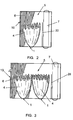
- a combustion envelope 4 is formed comprising a flame 3 and an oxidant/fuel mixing zone 2 between the flame 3 and the burner 1.
- FIGS 2 and 3 are schematic representations of conventional steam generating boilers utilizing a single and multiple burner(s) respectively.
- the interior walls 10 comprise a plurality of steam generating tubes 6 fluidly connected to a boiler bank (not shown). Thermal energy produced within the combustion envelope 4 radiantly heats the tubes 6 which in turn coduct thermal energy to the water in the tubes 6 for the purpose of generating steam.
- combustion furnace 5 In many steam generating boilers, the length and width of the combustion envelope 4 play an integral role in the design of the combustion furnace 5.
- the combustion furnace 5 In FM boilers, for example, the combustion furnace 5 is preferably designed sufficiently large enough to avoid excessive contact of the combustion envelope 4 with the furnace walls 10. Also known as flame impingement, seen in Fig 3 , excessive flame 3 contact with a furnace wall 10 may result in incomplete combustion, leading to higher emissions of CO and other combustion byproducts, or premature degradation, leading to costly repairs and boiler downtime. Accordingly, combustion furnaces 5 are generally designed to accommodate a given burner combustion envelope 4 while minimizing the possibility of flame impingement.
- Conventional burners generally utilize flow control mechanisms to control the axial and radial expansion of the combustion envelope 4. Radial expansion of the combustion envelope 4 is generally a function of swirl and the natural expansion of the fuel, oxidant, and flame. Some conventional burner designs utilize flow control mechanisms to restrict the natural radial expansion of the combustion envelope 4, resulting in a longer narrower flame. Shearing forces created by flow control mechanisms may also be used to influence the extent of oxidant/fuel mixing prior to combustion, thereby having an effect on emissions such as CO and NOx.
- oxidant and fuel The availability of oxidant and fuel and their ability to mix prior to combustion influences the length of a combustion envelope 4 within a combustion furnace 5. Longer flames generally result from an insufficient supply of oxidant or inadequate mixing of the oxidant and fuel within the combustion envelope 4. Shorter flames generally result from a sufficient supply of oxidant and adequate mixing of the oxidant and fuel within the combustion envelope 4. Flame length may also be influenced by the velocity at which fuel and/or oxidant streams enter the combustion envelope 4. Excessive velocities or momentary interruptions of fuel and/or oxidant streams may cause the burner flame 3 to lose ignition. Such loss of ignition is especially undesirable, as it may result in an accumulation of combustibles susceptible to violent explosion upon reignition.
- US 2 362 972 describes a gas burner having a mixing chamber at one end and having its opposite end open; means for introducing gas and air into said chamber; non-combustible porous packing in the open end of said burner through which the gas-air mixture diffuses; an insulated casing forming a primary combustion chamber into which the open end of the burner projects; means for admitting secondary air into the combustion chamber; said casing also forming a secondary combustion chamber adjacent said primary chamber; and a porous relatively thick layer of non-combustible material separating said primary and secondary combustion chambers and adapted to be heated to a high degree by the products of combustion.
- the present invention solves the aforementioned problems and provides a steam generating boiler capable of firing liquid fuels, gaseous fuels, or any combination thereof.
- An objective of the present invention is to provide a compact steam generating boiler.
- Another objective of the present invention is to provide a steam generating boiler with a radially wider and axially shorter combustion envelope than that of conventional steam generating boilers.
- Another objective of the present invention is to provide a low NOx and low CO steam generating boiler.
- Another objective of the present invention is to provide a steam generating boiler capable of passively maintaining a constant ignition source.
- Yet another objective of the present invention is to provide a means for designing a steam generating boiler of reduced size and weight as compared to that of a conventional steam generating boiler.
- a steam generating boiler according to the present invention comprises a combustion furnace (5), an oxidant inlet, a fuel inlet, a matrix means (8), and steam tubes (6).
- the present invention utilizes a combination of features to improve upon the design of conventional oil and gas fired steam generating boilers.
- Conventional oil and gas fired steam generating boilers include, but are not limited to: FM, High Capacity FM, PFM, PFI, PFT, SPB, and RB; all of which are described in Chapter 27 of Steam/its Generation and Use, 41th Edition, Kitto and Stultz, Eds., ⁇ 2005 The Babcock & Wilcox Company .
- FIG. 2 and 3 schematic representations of prior art FM boilers are shown.
- a baffle wall 20 separates a combustion furnace 5 from a boiler bank (not shown).
- Combustion envelope 4 is located inside the combustion furnace 5. Fuel and oxidant are delivered to burner 1, producing a combustion envelope 4 upon ignition.
- the interior walls 10 of the combustion furnace comprise a series of tubes 6 fluidly connected to a steam drum 7, producing steam used for process of electrical generation purposes.
- the conically diffusing shape of the combustion envelope 4 results in significant unused combustion furnace volume along side the combustion envelope 4 as it expands.
- An object of the present invention is to reduce unused combustion furnace volume.
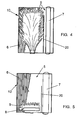
- the present invention provides a matrix 8, placed either within or prior to the flame of the combustion envelope. Referring to Figure 5 , a retrofit embodiment of the present invention is shown. Matrix 8 is placed with combustion furnace 5 downstream of the burner 1. Fuel and oxidant enter matrix 8, wherein the cross sectional design of matrix 8 provides a means for passively mixing gaseous streams and radially dispersing the resulting combustion envelope 9.
- gaseous fuel stream Provided to the matrix 8 is at least one gaseous fuel stream and at least one gaseous oxidant stream, or combinations thereof.
- the gaseous streams may enter the matrix 8 from any side.
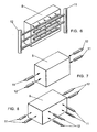
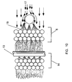
- Fig. 6 illustrates a preferred embodiment where the fuel stream 12 and oxidant stream 11 are introduced upstream of the matrix 8.
- the gaseous streams 11, 12 may enter the matrix 8 from the side(s) only or a combination of the front and side(s) of the matrix 8.
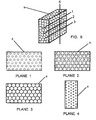
- the combustion apparatus is a matrix 8 comprising at least one layer of spheres.
- the spheres may be arranged in either a random or ordered manner within the matrix 8.
- the spheres may be hollow, solid, or porous in nature, or any combination thereof.
- the spheres may vary in size or be of a substantially similar size.
- the spheres comprise a high temperature metal capable of withstanding the extreme temperatures to which the matrix 8 may be exposed during the combustion of fossil fuels.
- Plane 1 is approximately 46 percent open
- plane two is approximately 31 percent open
- plane 3 is about 9 percent open
- plane 4 is about 58 percent open.
- An object of the present invention is improved mixing of the gaseous streams. Improved mixing is achieved in the presence of a matrix 8 comprising at least two cross sectional planes having different percentages of open area, such that a first cross sectional plane possesses a greater percentage of open area for gaseous flow than a second cross sectional plane.
- Plane 1 and plane 2 of Fig. 9 are two cross sectional planes having different percentages of open area for gaseous flow.
- Another object of the present invention is to radially disperse the combustion envelope. Radial dispersion is achieved in the presence of matrix 8 comprising at least two cross sectional planes having different percentages of open area, wherein the two planes are taken from different axes, and a first cross sectional plane possesses a greater percentage of open area for gaseous flow than a second cross sectional plane.
- Plane 3 and plane 4 of Fig. 9 are cross sectional planes of different axes having different percentages of open area for gaseous flow.
- the present invention provides a combustion apparatus that allows for improved steam generating boiler designs while retaining similar heat output.
- a schematic representation of the present invention retrofitted into a convention FM boiler is shown.
- the present invention radially expands the combustion envelope 4, resulting in a shorter combustion envelope 9, wherein unused combustion volume is shifted downstream of the combustion envelope 9.
- additional steam generating equipment can be placed in the unused combustion volume, thereby maximizing energy generation potential.
- a benefit of reducing the depth of a combustion furnace is the ability to develop new compact boiler designs without sacrificing heat output.
- Combustion furnaces 5 in steam generating boilers are generally designed to accommodate a given combustion envelope 4 while minimizing risk of flame impingement. Shortening the combustion envelope 4 allows for significant furnace depth reduction at any given heat output.
- Use of the present invention reduces boiler size, thus weight, as shorter boilers utilize considerably less raw materials to make boiler walls and tubes 6.
- a matrix 8 according to the present invention may be placed anywhere within the combustion envelope 4.
- the matrix 8 is placed within the mixing zone 2 and will be of a depth sufficient to allow combustion to begin within the matrix 8 and combustion flames 3 to exit the matrix 8 downstream of where fuel and oxidant are introduced.
- flame width is maximized as ignition of the combustible stream creates expansive forces, enabling further radial expansion within the matrix 8.
- the matrix 8 is comprised of a material capable of retaining thermal heat.
- the thermal heat retained within the matrix elements provides a thermal reservoir sufficient to maintain ignition; thereby avoiding undesirable situations associated with delayed reignition.
- a steam generating boiler may utilize more than one matrix 8.
- Figure 10 is a graphic representation of an embodiment of the present invention where two matrixes are used to facilitate staged combustion.
- a second matrix 14 is located downstream of a first matrix 8.
- the first matrix 8 is provided with a fuel stream 18 and substoichiometric oxidant 17 to inhibit the production of undesirable combustion byproducts such as NOx.
- a second oxidant stream 13, providing sufficient oxygen to burn remaining fuel, is provided downstream of the first matrix 8 and upstream of the second matrix 14.
- Fig 11 illustrates an alternative two matrix staged combustion embodiment according to the present invention.
- cooling tubes 15 are placed between the two matrixes 8, 14 for the purpose of controlling flame temperature and the formation of thermal NOx.
- a perforated plate 150 may also be placed upstream of the first matrix 8, serving the function of acting as a flame arrestor and/or pre distributing the substoichiometric oxidant 17.
- a sensor 16 may be placed within the combustion furnace for observing the combustion process within the combustion furnace 5.
- a igniter 160 may be placed within the combustion furnace for preheating the matrix 8 or igniting a fuel and oxidant.
- Fig. 12 provides a graphical representation of an example not according to the invention.
- the matrix 8 comprises a random or ordered block of fibers or interlaced particles. Between the fibers and particles of this embodiment are series of internal passage having cross sections of varying open area for gaseous flow providing a means for gaseous fuel and oxidant streams to passively mix and radially disperse within the matrix 8.
- Section A-A provides a cross section view of the present embodiment.
- Fig. 13 provides a graphical representation of another example not according to the invention.
- the matrix 8 comprises fired or fitted tiles with venturi holes 19.
- An expanded view of a Section B-B of this embodiment is shown where the cross sectional dimensions of the venturi holes 19 are shown varying along the depth of the matrix 8.
- oxidant and/fuel may be fed to the matrix 8 in multiple streams.
- the spheres may be coated with any number of chemical substrates known to one of ordinary skill in the art for the purpose of altering the chemistry of the fuel, enhancing combustion, and reducing pollutant emissions.
- the matrix 8 itself can be rectangular, circular, or of any other geometric design.
- the matrix 8 elements of the present invention are held captive by a suitable apparatus for preventing movement between the spheres.
- suitable apparatus are, but are not limited to, wire frames and/or chemically or mechanically bonding the matrix 8 elements to one another.
- multiple matrixes may be arranged in parallel within a boiler.
- multiple fuels may be combusted simultaneously, thereby providing combustion fuel flexibility to boiler designs.
- forced air or recirculation fans may be utilized to create a pressure differential across the matrix 8 to either promote or restrict gaseous flow there through.
Landscapes
- Engineering & Computer Science (AREA)
- Chemical & Material Sciences (AREA)
- Combustion & Propulsion (AREA)
- Mechanical Engineering (AREA)
- General Engineering & Computer Science (AREA)
- Physics & Mathematics (AREA)
- Thermal Sciences (AREA)
- Combustion Of Fluid Fuel (AREA)
- Control Of Steam Boilers And Waste-Gas Boilers (AREA)
- Feeding And Controlling Fuel (AREA)
- Massaging Devices (AREA)
Priority Applications (1)
| Application Number | Priority Date | Filing Date | Title |
|---|---|---|---|
| PL06718277T PL1836439T3 (pl) | 2005-01-12 | 2006-01-12 | Środek macierzowy do redukowania objętości spalania |
Applications Claiming Priority (2)
| Application Number | Priority Date | Filing Date | Title |
|---|---|---|---|
| US64321905P | 2005-01-12 | 2005-01-12 | |
| PCT/US2006/001185 WO2006076549A1 (en) | 2005-01-12 | 2006-01-12 | Matrix means for reducing combustion volume |
Publications (3)
| Publication Number | Publication Date |
|---|---|
| EP1836439A1 EP1836439A1 (en) | 2007-09-26 |
| EP1836439A4 EP1836439A4 (en) | 2013-09-04 |
| EP1836439B1 true EP1836439B1 (en) | 2015-07-01 |
Family
ID=36677968
Family Applications (1)
| Application Number | Title | Priority Date | Filing Date |
|---|---|---|---|
| EP06718277.4A Expired - Lifetime EP1836439B1 (en) | 2005-01-12 | 2006-01-12 | Matrix means for reducing combustion volume |
Country Status (17)
| Country | Link |
|---|---|
| EP (1) | EP1836439B1 (pl) |
| JP (1) | JP5232474B2 (pl) |
| KR (1) | KR101362671B1 (pl) |
| CN (1) | CN101120208B (pl) |
| AU (1) | AU2006204840B2 (pl) |
| BR (1) | BRPI0606693B1 (pl) |
| CA (1) | CA2594739C (pl) |
| DK (1) | DK1836439T3 (pl) |
| ES (1) | ES2546645T3 (pl) |
| HU (1) | HUE027866T2 (pl) |
| MX (1) | MX2007008516A (pl) |
| NO (1) | NO340477B1 (pl) |
| PL (1) | PL1836439T3 (pl) |
| PT (1) | PT1836439E (pl) |
| RU (1) | RU2410599C2 (pl) |
| WO (1) | WO2006076549A1 (pl) |
| ZA (1) | ZA200705847B (pl) |
Families Citing this family (1)
| Publication number | Priority date | Publication date | Assignee | Title |
|---|---|---|---|---|
| EP3336427B1 (en) * | 2016-12-16 | 2019-07-03 | Ikerlan, S. Coop. | Gas burner |
Family Cites Families (21)
| Publication number | Priority date | Publication date | Assignee | Title |
|---|---|---|---|---|
| US65846A (en) * | 1867-06-18 | van tine | ||
| US2362972A (en) * | 1939-12-26 | 1944-11-21 | Brownback Henry Lowe | Gas burner |
| US3322179A (en) * | 1963-04-09 | 1967-05-30 | Paul H Goodell | Fuel burner having porous matrix |
| US3921712A (en) * | 1970-03-02 | 1975-11-25 | American Standard Inc | Heat exchanger structure for a compact boiler and the like |
| US4027476A (en) * | 1973-10-15 | 1977-06-07 | Rocket Research Corporation | Composite catalyst bed and method for making the same |
| JPS61147010A (ja) * | 1984-12-19 | 1986-07-04 | Nippon Steel Corp | 高温輻射パネルバ−ナ− |
| JPS62258917A (ja) * | 1986-04-18 | 1987-11-11 | Miura Co Ltd | セラミック粒子からなる助燃体を用いた表面燃焼バーナ |
| EP0484280B1 (de) * | 1990-10-31 | 1994-12-28 | Koenig Ag | Anlage zur Reinigung von schadstoffbelasteter Luft |
| JPH0611102A (ja) * | 1992-06-30 | 1994-01-21 | Ishikawajima Harima Heavy Ind Co Ltd | ボイラ燃焼装置 |
| US5326631A (en) * | 1993-06-07 | 1994-07-05 | Alzeta Corporation | Unsintered fiber burner made with metal fibers, ceramic fibers and binding agent |
| US5511974A (en) * | 1994-10-21 | 1996-04-30 | Burnham Properties Corporation | Ceramic foam low emissions burner for natural gas-fired residential appliances |
| JP3082826B2 (ja) * | 1994-10-24 | 2000-08-28 | 三菱重工業株式会社 | 排熱回収装置 |
| JP2663933B2 (ja) * | 1995-11-29 | 1997-10-15 | 三浦工業株式会社 | ボイラー |
| DE19547506B4 (de) * | 1995-12-19 | 2008-06-05 | Airbus Deutschland Gmbh | Verfahren und Brenner zum Verbrennen von Wasserstoff |
| DE29816864U1 (de) * | 1998-09-19 | 2000-01-27 | Viessmann Werke GmbH & Co., 35108 Allendorf | Heizkesselgebläsebrenner |
| US6289851B1 (en) * | 2000-10-18 | 2001-09-18 | Institute Of Gas Technology | Compact low-nox high-efficiency heating apparatus |
| RU2206820C1 (ru) * | 2001-10-04 | 2003-06-20 | Максимов Лев Николаевич | Котел-парогенератор |
| US6921516B2 (en) * | 2001-10-15 | 2005-07-26 | General Motors Corporation | Reactor system including auto ignition and carbon suppression foam |
| JP2003262313A (ja) * | 2002-03-08 | 2003-09-19 | Osaka Gas Co Ltd | 燃焼装置 |
| JP3722775B2 (ja) * | 2002-04-05 | 2005-11-30 | 株式会社タクマ | 予混合ガス燃焼装置 |
| US6971336B1 (en) * | 2005-01-05 | 2005-12-06 | Gas Technology Institute | Super low NOx, high efficiency, compact firetube boiler |
-
2006
- 2006-01-12 KR KR1020077017063A patent/KR101362671B1/ko not_active Expired - Fee Related
- 2006-01-12 CA CA2594739A patent/CA2594739C/en not_active Expired - Fee Related
- 2006-01-12 JP JP2007551388A patent/JP5232474B2/ja not_active Expired - Lifetime
- 2006-01-12 MX MX2007008516A patent/MX2007008516A/es active IP Right Grant
- 2006-01-12 HU HUE06718277A patent/HUE027866T2/en unknown
- 2006-01-12 RU RU2007144255/06A patent/RU2410599C2/ru not_active IP Right Cessation
- 2006-01-12 PL PL06718277T patent/PL1836439T3/pl unknown
- 2006-01-12 PT PT67182774T patent/PT1836439E/pt unknown
- 2006-01-12 WO PCT/US2006/001185 patent/WO2006076549A1/en not_active Ceased
- 2006-01-12 ES ES06718277.4T patent/ES2546645T3/es not_active Expired - Lifetime
- 2006-01-12 EP EP06718277.4A patent/EP1836439B1/en not_active Expired - Lifetime
- 2006-01-12 AU AU2006204840A patent/AU2006204840B2/en not_active Ceased
- 2006-01-12 DK DK06718277.4T patent/DK1836439T3/en active
- 2006-01-12 CN CN200680005070XA patent/CN101120208B/zh not_active Expired - Fee Related
- 2006-01-12 BR BRPI0606693-3A patent/BRPI0606693B1/pt not_active IP Right Cessation
-
2007
- 2007-07-13 ZA ZA200705847A patent/ZA200705847B/en unknown
- 2007-07-24 NO NO20073886A patent/NO340477B1/no not_active IP Right Cessation
Also Published As
| Publication number | Publication date |
|---|---|
| RU2007144255A (ru) | 2009-06-10 |
| CA2594739A1 (en) | 2006-07-20 |
| DK1836439T3 (en) | 2015-09-28 |
| KR20070101868A (ko) | 2007-10-17 |
| AU2006204840B2 (en) | 2011-09-29 |
| CA2594739C (en) | 2014-03-25 |
| AU2006204840A1 (en) | 2006-07-20 |
| KR101362671B1 (ko) | 2014-02-12 |
| ZA200705847B (en) | 2008-07-30 |
| WO2006076549A1 (en) | 2006-07-20 |
| NO340477B1 (no) | 2017-05-02 |
| MX2007008516A (es) | 2007-09-19 |
| CN101120208A (zh) | 2008-02-06 |
| CN101120208B (zh) | 2010-05-19 |
| BRPI0606693B1 (pt) | 2019-05-14 |
| JP5232474B2 (ja) | 2013-07-10 |
| BRPI0606693A2 (pt) | 2009-07-14 |
| EP1836439A4 (en) | 2013-09-04 |
| EP1836439A1 (en) | 2007-09-26 |
| JP2008527310A (ja) | 2008-07-24 |
| RU2410599C2 (ru) | 2011-01-27 |
| ES2546645T3 (es) | 2015-09-25 |
| PT1836439E (pt) | 2015-10-12 |
| HUE027866T2 (en) | 2016-11-28 |
| NO20073886L (no) | 2007-10-08 |
| PL1836439T3 (pl) | 2015-12-31 |
Similar Documents
| Publication | Publication Date | Title |
|---|---|---|
| RU2589587C1 (ru) | Горелка для газообразного топлива с высоким энергосбережением и эффективностью сгорания, с низкой эмиссией загрязняющих веществ и высокой теплопередачей | |
| US10760784B2 (en) | Burner including a perforated flame holder spaced away from a fuel nozzle | |
| CA2510713C (en) | Staged combustion system with ignition-assisted fuel lances | |
| CN102305415B (zh) | 一种富氧环境下的等离子无油点火系统 | |
| CN101983305A (zh) | 燃烧器 | |
| EP1836439B1 (en) | Matrix means for reducing combustion volume | |
| US7493876B2 (en) | Passive mixing device for staged combustion of gaseous boiler fuels | |
| CN114110580A (zh) | 一种低氮燃烧器 | |
| CN201100636Y (zh) | 双腔微油点火燃烧装置 | |
| RU50280U1 (ru) | Вспомогательное горелочное устройство для плазменного воспламенения и стабилизации горения низкореакционного пылеугольного топлива основных горелок теплового агрегата | |
| CN113991153A (zh) | 一种尾气燃烧器及固体氧化物燃料电池系统 | |
| FI127741B (fi) | Bioöljypoltin | |
| RU2300053C1 (ru) | Вспомогательное горелочное устройство для плазменного воспламенения и стабилизации горения низкореакционного пылеугольного топлива основных горелок теплового агрегата | |
| JP2012093088A (ja) | Nox排出削減方法 | |
| JP2008045819A (ja) | 中心空気噴出口を有するバーナー | |
| CS245928B1 (cs) | Zapalovací a stabilizační hořák |
Legal Events
| Date | Code | Title | Description |
|---|---|---|---|
| PUAI | Public reference made under article 153(3) epc to a published international application that has entered the european phase |
Free format text: ORIGINAL CODE: 0009012 |
|
| 17P | Request for examination filed |
Effective date: 20070723 |
|
| AK | Designated contracting states |
Kind code of ref document: A1 Designated state(s): AT BE BG CH CY CZ DE DK EE ES FI FR GB GR HU IE IS IT LI LT LU LV MC NL PL PT RO SE SI SK TR |
|
| RIN1 | Information on inventor provided before grant (corrected) |
Inventor name: LENZER, RONALD, C. Inventor name: STREMPEK, JOSEPH, ROBERT |
|
| DAX | Request for extension of the european patent (deleted) | ||
| RAP1 | Party data changed (applicant data changed or rights of an application transferred) |
Owner name: BABCOCK & WILCOX POWER GENERATION GROUP, INC. |
|
| A4 | Supplementary search report drawn up and despatched |
Effective date: 20130807 |
|
| RIC1 | Information provided on ipc code assigned before grant |
Ipc: F23D 14/84 20060101ALI20130801BHEP Ipc: F23C 6/04 20060101ALI20130801BHEP Ipc: F22B 13/00 20060101ALI20130801BHEP Ipc: F23D 17/00 20060101ALI20130801BHEP Ipc: F23D 3/40 20060101AFI20130801BHEP |
|
| 17Q | First examination report despatched |
Effective date: 20140307 |
|
| REG | Reference to a national code |
Ref country code: DE Ref legal event code: R079 Ref document number: 602006045827 Country of ref document: DE Free format text: PREVIOUS MAIN CLASS: F23D0003400000 Ipc: F23C0006040000 |
|
| GRAP | Despatch of communication of intention to grant a patent |
Free format text: ORIGINAL CODE: EPIDOSNIGR1 |
|
| RIC1 | Information provided on ipc code assigned before grant |
Ipc: F23D 17/00 20060101ALI20150120BHEP Ipc: F22B 21/34 20060101ALI20150120BHEP Ipc: F23D 14/84 20060101ALI20150120BHEP Ipc: F23C 6/04 20060101AFI20150120BHEP |
|
| INTG | Intention to grant announced |
Effective date: 20150213 |
|
| GRAS | Grant fee paid |
Free format text: ORIGINAL CODE: EPIDOSNIGR3 |
|
| GRAA | (expected) grant |
Free format text: ORIGINAL CODE: 0009210 |
|
| AK | Designated contracting states |
Kind code of ref document: B1 Designated state(s): AT BE BG CH CY CZ DE DK EE ES FI FR GB GR HU IE IS IT LI LT LU LV MC NL PL PT RO SE SI SK TR |
|
| REG | Reference to a national code |
Ref country code: GB Ref legal event code: FG4D |
|
| REG | Reference to a national code |
Ref country code: DE Ref legal event code: R081 Ref document number: 602006045827 Country of ref document: DE Owner name: THE BABCOCK & WILCOX CO., BARBERTON, US Free format text: FORMER OWNER: THE BABCOCK & WILCOX CO., BARBERTON, OHIO, US |
|
| REG | Reference to a national code |
Ref country code: AT Ref legal event code: REF Ref document number: 734187 Country of ref document: AT Kind code of ref document: T Effective date: 20150715 Ref country code: CH Ref legal event code: EP |
|
| REG | Reference to a national code |
Ref country code: IE Ref legal event code: FG4D |
|
| REG | Reference to a national code |
Ref country code: DE Ref legal event code: R096 Ref document number: 602006045827 Country of ref document: DE |
|
| REG | Reference to a national code |
Ref country code: RO Ref legal event code: EPE |
|
| REG | Reference to a national code |
Ref country code: ES Ref legal event code: FG2A Ref document number: 2546645 Country of ref document: ES Kind code of ref document: T3 Effective date: 20150925 |
|
| REG | Reference to a national code |
Ref country code: DK Ref legal event code: T3 Effective date: 20150921 |
|
| REG | Reference to a national code |
Ref country code: PT Ref legal event code: SC4A Free format text: AVAILABILITY OF NATIONAL TRANSLATION Effective date: 20150907 |
|
| REG | Reference to a national code |
Ref country code: DE Ref legal event code: R082 Ref document number: 602006045827 Country of ref document: DE Representative=s name: D YOUNG & CO LLP, GB Ref country code: DE Ref legal event code: R081 Ref document number: 602006045827 Country of ref document: DE Owner name: THE BABCOCK & WILCOX CO., BARBERTON, US Free format text: FORMER OWNER: BABCOCK & WILCOX POWER GENERATION GROUP, INC., BARBERTON, OHIO, US |
|
| RAP2 | Party data changed (patent owner data changed or rights of a patent transferred) |
Owner name: THE BABCOCK & WILCOX COMPANY |
|
| REG | Reference to a national code |
Ref country code: NL Ref legal event code: MP Effective date: 20150701 |
|
| REG | Reference to a national code |
Ref country code: LT Ref legal event code: MG4D |
|
| REG | Reference to a national code |
Ref country code: PL Ref legal event code: T3 |
|
| PG25 | Lapsed in a contracting state [announced via postgrant information from national office to epo] |
Ref country code: FI Free format text: LAPSE BECAUSE OF FAILURE TO SUBMIT A TRANSLATION OF THE DESCRIPTION OR TO PAY THE FEE WITHIN THE PRESCRIBED TIME-LIMIT Effective date: 20150701 Ref country code: LT Free format text: LAPSE BECAUSE OF FAILURE TO SUBMIT A TRANSLATION OF THE DESCRIPTION OR TO PAY THE FEE WITHIN THE PRESCRIBED TIME-LIMIT Effective date: 20150701 Ref country code: LV Free format text: LAPSE BECAUSE OF FAILURE TO SUBMIT A TRANSLATION OF THE DESCRIPTION OR TO PAY THE FEE WITHIN THE PRESCRIBED TIME-LIMIT Effective date: 20150701 Ref country code: GR Free format text: LAPSE BECAUSE OF FAILURE TO SUBMIT A TRANSLATION OF THE DESCRIPTION OR TO PAY THE FEE WITHIN THE PRESCRIBED TIME-LIMIT Effective date: 20151002 |
|
| PG25 | Lapsed in a contracting state [announced via postgrant information from national office to epo] |
Ref country code: SE Free format text: LAPSE BECAUSE OF FAILURE TO SUBMIT A TRANSLATION OF THE DESCRIPTION OR TO PAY THE FEE WITHIN THE PRESCRIBED TIME-LIMIT Effective date: 20150701 Ref country code: IS Free format text: LAPSE BECAUSE OF FAILURE TO SUBMIT A TRANSLATION OF THE DESCRIPTION OR TO PAY THE FEE WITHIN THE PRESCRIBED TIME-LIMIT Effective date: 20151101 |
|
| REG | Reference to a national code |
Ref country code: DE Ref legal event code: R097 Ref document number: 602006045827 Country of ref document: DE |
|
| PG25 | Lapsed in a contracting state [announced via postgrant information from national office to epo] |
Ref country code: EE Free format text: LAPSE BECAUSE OF FAILURE TO SUBMIT A TRANSLATION OF THE DESCRIPTION OR TO PAY THE FEE WITHIN THE PRESCRIBED TIME-LIMIT Effective date: 20150701 |
|
| REG | Reference to a national code |
Ref country code: SK Ref legal event code: T3 Ref document number: E 20040 Country of ref document: SK |
|
| PLBE | No opposition filed within time limit |
Free format text: ORIGINAL CODE: 0009261 |
|
| STAA | Information on the status of an ep patent application or granted ep patent |
Free format text: STATUS: NO OPPOSITION FILED WITHIN TIME LIMIT |
|
| REG | Reference to a national code |
Ref country code: AT Ref legal event code: HC Ref document number: 734187 Country of ref document: AT Kind code of ref document: T Owner name: THE BABCOCK & WILCOX COMPANY, US Effective date: 20160411 |
|
| PG25 | Lapsed in a contracting state [announced via postgrant information from national office to epo] |
Ref country code: BE Free format text: LAPSE BECAUSE OF NON-PAYMENT OF DUE FEES Effective date: 20160131 |
|
| 26N | No opposition filed |
Effective date: 20160404 |
|
| PG25 | Lapsed in a contracting state [announced via postgrant information from national office to epo] |
Ref country code: SI Free format text: LAPSE BECAUSE OF FAILURE TO SUBMIT A TRANSLATION OF THE DESCRIPTION OR TO PAY THE FEE WITHIN THE PRESCRIBED TIME-LIMIT Effective date: 20150701 Ref country code: LU Free format text: LAPSE BECAUSE OF FAILURE TO SUBMIT A TRANSLATION OF THE DESCRIPTION OR TO PAY THE FEE WITHIN THE PRESCRIBED TIME-LIMIT Effective date: 20160112 |
|
| REG | Reference to a national code |
Ref country code: CH Ref legal event code: PL |
|
| REG | Reference to a national code |
Ref country code: HU Ref legal event code: HC9C Owner name: THE BABCOCK & WILCOX COMPANY, US Free format text: FORMER OWNER(S): BABCOCK & WILCOX POWER GENERATION GROUP, INC., US |
|
| PG25 | Lapsed in a contracting state [announced via postgrant information from national office to epo] |
Ref country code: MC Free format text: LAPSE BECAUSE OF FAILURE TO SUBMIT A TRANSLATION OF THE DESCRIPTION OR TO PAY THE FEE WITHIN THE PRESCRIBED TIME-LIMIT Effective date: 20150701 |
|
| REG | Reference to a national code |
Ref country code: FR Ref legal event code: ST Effective date: 20160930 |
|
| PG25 | Lapsed in a contracting state [announced via postgrant information from national office to epo] |
Ref country code: LI Free format text: LAPSE BECAUSE OF NON-PAYMENT OF DUE FEES Effective date: 20160131 Ref country code: CH Free format text: LAPSE BECAUSE OF NON-PAYMENT OF DUE FEES Effective date: 20160131 |
|
| REG | Reference to a national code |
Ref country code: IE Ref legal event code: MM4A |
|
| REG | Reference to a national code |
Ref country code: HU Ref legal event code: AG4A Ref document number: E027866 Country of ref document: HU |
|
| PG25 | Lapsed in a contracting state [announced via postgrant information from national office to epo] |
Ref country code: FR Free format text: LAPSE BECAUSE OF NON-PAYMENT OF DUE FEES Effective date: 20160201 |
|
| PG25 | Lapsed in a contracting state [announced via postgrant information from national office to epo] |
Ref country code: BE Free format text: LAPSE BECAUSE OF FAILURE TO SUBMIT A TRANSLATION OF THE DESCRIPTION OR TO PAY THE FEE WITHIN THE PRESCRIBED TIME-LIMIT Effective date: 20150701 |
|
| PG25 | Lapsed in a contracting state [announced via postgrant information from national office to epo] |
Ref country code: IE Free format text: LAPSE BECAUSE OF NON-PAYMENT OF DUE FEES Effective date: 20160112 |
|
| REG | Reference to a national code |
Ref country code: AT Ref legal event code: UEP Ref document number: 734187 Country of ref document: AT Kind code of ref document: T Effective date: 20150701 |
|
| PG25 | Lapsed in a contracting state [announced via postgrant information from national office to epo] |
Ref country code: NL Free format text: LAPSE BECAUSE OF FAILURE TO SUBMIT A TRANSLATION OF THE DESCRIPTION OR TO PAY THE FEE WITHIN THE PRESCRIBED TIME-LIMIT Effective date: 20150701 |
|
| PG25 | Lapsed in a contracting state [announced via postgrant information from national office to epo] |
Ref country code: CY Free format text: LAPSE BECAUSE OF FAILURE TO SUBMIT A TRANSLATION OF THE DESCRIPTION OR TO PAY THE FEE WITHIN THE PRESCRIBED TIME-LIMIT Effective date: 20150701 |
|
| PG25 | Lapsed in a contracting state [announced via postgrant information from national office to epo] |
Ref country code: TR Free format text: LAPSE BECAUSE OF FAILURE TO SUBMIT A TRANSLATION OF THE DESCRIPTION OR TO PAY THE FEE WITHIN THE PRESCRIBED TIME-LIMIT Effective date: 20150701 |
|
| PG25 | Lapsed in a contracting state [announced via postgrant information from national office to epo] |
Ref country code: BG Free format text: LAPSE BECAUSE OF FAILURE TO SUBMIT A TRANSLATION OF THE DESCRIPTION OR TO PAY THE FEE WITHIN THE PRESCRIBED TIME-LIMIT Effective date: 20150701 |
|
| PGFP | Annual fee paid to national office [announced via postgrant information from national office to epo] |
Ref country code: PT Payment date: 20191220 Year of fee payment: 15 Ref country code: SK Payment date: 20191218 Year of fee payment: 15 Ref country code: RO Payment date: 20191220 Year of fee payment: 15 |
|
| PGFP | Annual fee paid to national office [announced via postgrant information from national office to epo] |
Ref country code: IT Payment date: 20200123 Year of fee payment: 15 Ref country code: ES Payment date: 20200205 Year of fee payment: 15 Ref country code: DK Payment date: 20200129 Year of fee payment: 15 Ref country code: GB Payment date: 20200127 Year of fee payment: 15 Ref country code: DE Payment date: 20200129 Year of fee payment: 15 Ref country code: PL Payment date: 20191218 Year of fee payment: 15 Ref country code: HU Payment date: 20200106 Year of fee payment: 15 Ref country code: AT Payment date: 20191219 Year of fee payment: 15 |
|
| PGFP | Annual fee paid to national office [announced via postgrant information from national office to epo] |
Ref country code: CZ Payment date: 20191231 Year of fee payment: 15 |
|
| REG | Reference to a national code |
Ref country code: DE Ref legal event code: R082 Ref document number: 602006045827 Country of ref document: DE Representative=s name: D YOUNG & CO LLP, DE |
|
| REG | Reference to a national code |
Ref country code: DE Ref legal event code: R119 Ref document number: 602006045827 Country of ref document: DE |
|
| REG | Reference to a national code |
Ref country code: DK Ref legal event code: EBP Effective date: 20210131 |
|
| REG | Reference to a national code |
Ref country code: AT Ref legal event code: MM01 Ref document number: 734187 Country of ref document: AT Kind code of ref document: T Effective date: 20210112 |
|
| GBPC | Gb: european patent ceased through non-payment of renewal fee |
Effective date: 20210112 |
|
| REG | Reference to a national code |
Ref country code: SK Ref legal event code: MM4A Ref document number: E 20040 Country of ref document: SK Effective date: 20210112 |
|
| PG25 | Lapsed in a contracting state [announced via postgrant information from national office to epo] |
Ref country code: HU Free format text: LAPSE BECAUSE OF NON-PAYMENT OF DUE FEES Effective date: 20210113 Ref country code: AT Free format text: LAPSE BECAUSE OF NON-PAYMENT OF DUE FEES Effective date: 20210112 Ref country code: CZ Free format text: LAPSE BECAUSE OF NON-PAYMENT OF DUE FEES Effective date: 20210112 |
|
| PG25 | Lapsed in a contracting state [announced via postgrant information from national office to epo] |
Ref country code: RO Free format text: LAPSE BECAUSE OF NON-PAYMENT OF DUE FEES Effective date: 20210112 Ref country code: PT Free format text: LAPSE BECAUSE OF NON-PAYMENT OF DUE FEES Effective date: 20210712 Ref country code: SK Free format text: LAPSE BECAUSE OF NON-PAYMENT OF DUE FEES Effective date: 20210112 Ref country code: DE Free format text: LAPSE BECAUSE OF NON-PAYMENT OF DUE FEES Effective date: 20210803 Ref country code: GB Free format text: LAPSE BECAUSE OF NON-PAYMENT OF DUE FEES Effective date: 20210112 |
|
| PG25 | Lapsed in a contracting state [announced via postgrant information from national office to epo] |
Ref country code: DK Free format text: LAPSE BECAUSE OF NON-PAYMENT OF DUE FEES Effective date: 20210131 |
|
| REG | Reference to a national code |
Ref country code: ES Ref legal event code: FD2A Effective date: 20220422 |
|
| PG25 | Lapsed in a contracting state [announced via postgrant information from national office to epo] |
Ref country code: IT Free format text: LAPSE BECAUSE OF NON-PAYMENT OF DUE FEES Effective date: 20210112 |
|
| PG25 | Lapsed in a contracting state [announced via postgrant information from national office to epo] |
Ref country code: ES Free format text: LAPSE BECAUSE OF NON-PAYMENT OF DUE FEES Effective date: 20210113 |
|
| PG25 | Lapsed in a contracting state [announced via postgrant information from national office to epo] |
Ref country code: PL Free format text: LAPSE BECAUSE OF NON-PAYMENT OF DUE FEES Effective date: 20210112 |