EP1835151B1 - Motorsteuerung - Google Patents
Motorsteuerung Download PDFInfo
- Publication number
- EP1835151B1 EP1835151B1 EP07103901A EP07103901A EP1835151B1 EP 1835151 B1 EP1835151 B1 EP 1835151B1 EP 07103901 A EP07103901 A EP 07103901A EP 07103901 A EP07103901 A EP 07103901A EP 1835151 B1 EP1835151 B1 EP 1835151B1
- Authority
- EP
- European Patent Office
- Prior art keywords
- expansion
- ratio
- load
- timing
- engine
- Prior art date
- Legal status (The legal status is an assumption and is not a legal conclusion. Google has not performed a legal analysis and makes no representation as to the accuracy of the status listed.)
- Expired - Fee Related
Links
- 230000001276 controlling effect Effects 0.000 claims description 66
- 238000000034 method Methods 0.000 claims description 27
- 230000008569 process Effects 0.000 claims description 19
- 230000007423 decrease Effects 0.000 claims description 9
- 230000033001 locomotion Effects 0.000 claims description 7
- 230000001105 regulatory effect Effects 0.000 claims description 4
- 230000007246 mechanism Effects 0.000 description 28
- 239000000446 fuel Substances 0.000 description 19
- 230000006835 compression Effects 0.000 description 16
- 238000007906 compression Methods 0.000 description 16
- 230000004044 response Effects 0.000 description 16
- 238000004891 communication Methods 0.000 description 8
- 238000002485 combustion reaction Methods 0.000 description 7
- 238000001514 detection method Methods 0.000 description 7
- 230000008859 change Effects 0.000 description 5
- 238000010586 diagram Methods 0.000 description 4
- 238000003780 insertion Methods 0.000 description 3
- 230000037431 insertion Effects 0.000 description 3
- 230000002159 abnormal effect Effects 0.000 description 2
- 238000006073 displacement reaction Methods 0.000 description 2
- 238000002347 injection Methods 0.000 description 2
- 239000007924 injection Substances 0.000 description 2
- 238000012986 modification Methods 0.000 description 2
- 230000004048 modification Effects 0.000 description 2
- XLYOFNOQVPJJNP-UHFFFAOYSA-N water Substances O XLYOFNOQVPJJNP-UHFFFAOYSA-N 0.000 description 2
- 230000005540 biological transmission Effects 0.000 description 1
- 230000006866 deterioration Effects 0.000 description 1
- 238000005516 engineering process Methods 0.000 description 1
- 239000012530 fluid Substances 0.000 description 1
- 230000006870 function Effects 0.000 description 1
- 239000000463 material Substances 0.000 description 1
- 238000012545 processing Methods 0.000 description 1
- 238000005086 pumping Methods 0.000 description 1
- 230000000979 retarding effect Effects 0.000 description 1
- 239000013585 weight reducing agent Substances 0.000 description 1
Images


Classifications
-
- F—MECHANICAL ENGINEERING; LIGHTING; HEATING; WEAPONS; BLASTING
- F01—MACHINES OR ENGINES IN GENERAL; ENGINE PLANTS IN GENERAL; STEAM ENGINES
- F01L—CYCLICALLY OPERATING VALVES FOR MACHINES OR ENGINES
- F01L1/00—Valve-gear or valve arrangements, e.g. lift-valve gear
- F01L1/34—Valve-gear or valve arrangements, e.g. lift-valve gear characterised by the provision of means for changing the timing of the valves without changing the duration of opening and without affecting the magnitude of the valve lift
- F01L1/344—Valve-gear or valve arrangements, e.g. lift-valve gear characterised by the provision of means for changing the timing of the valves without changing the duration of opening and without affecting the magnitude of the valve lift changing the angular relationship between crankshaft and camshaft, e.g. using helicoidal gear
- F01L1/3442—Valve-gear or valve arrangements, e.g. lift-valve gear characterised by the provision of means for changing the timing of the valves without changing the duration of opening and without affecting the magnitude of the valve lift changing the angular relationship between crankshaft and camshaft, e.g. using helicoidal gear using hydraulic chambers with variable volume to transmit the rotating force
-
- F—MECHANICAL ENGINEERING; LIGHTING; HEATING; WEAPONS; BLASTING
- F01—MACHINES OR ENGINES IN GENERAL; ENGINE PLANTS IN GENERAL; STEAM ENGINES
- F01L—CYCLICALLY OPERATING VALVES FOR MACHINES OR ENGINES
- F01L1/00—Valve-gear or valve arrangements, e.g. lift-valve gear
- F01L1/02—Valve drive
- F01L1/022—Chain drive
-
- F—MECHANICAL ENGINEERING; LIGHTING; HEATING; WEAPONS; BLASTING
- F01—MACHINES OR ENGINES IN GENERAL; ENGINE PLANTS IN GENERAL; STEAM ENGINES
- F01L—CYCLICALLY OPERATING VALVES FOR MACHINES OR ENGINES
- F01L13/00—Modifications of valve-gear to facilitate reversing, braking, starting, changing compression ratio, or other specific operations
- F01L13/0015—Modifications of valve-gear to facilitate reversing, braking, starting, changing compression ratio, or other specific operations for optimising engine performances by modifying valve lift according to various working parameters, e.g. rotational speed, load, torque
- F01L13/0021—Modifications of valve-gear to facilitate reversing, braking, starting, changing compression ratio, or other specific operations for optimising engine performances by modifying valve lift according to various working parameters, e.g. rotational speed, load, torque by modification of rocker arm ratio
- F01L13/0026—Modifications of valve-gear to facilitate reversing, braking, starting, changing compression ratio, or other specific operations for optimising engine performances by modifying valve lift according to various working parameters, e.g. rotational speed, load, torque by modification of rocker arm ratio by means of an eccentric
-
- F—MECHANICAL ENGINEERING; LIGHTING; HEATING; WEAPONS; BLASTING
- F02—COMBUSTION ENGINES; HOT-GAS OR COMBUSTION-PRODUCT ENGINE PLANTS
- F02B—INTERNAL-COMBUSTION PISTON ENGINES; COMBUSTION ENGINES IN GENERAL
- F02B75/00—Other engines
- F02B75/04—Engines with variable distances between pistons at top dead-centre positions and cylinder heads
- F02B75/048—Engines with variable distances between pistons at top dead-centre positions and cylinder heads by means of a variable crank stroke length
-
- F—MECHANICAL ENGINEERING; LIGHTING; HEATING; WEAPONS; BLASTING
- F02—COMBUSTION ENGINES; HOT-GAS OR COMBUSTION-PRODUCT ENGINE PLANTS
- F02D—CONTROLLING COMBUSTION ENGINES
- F02D13/00—Controlling the engine output power by varying inlet or exhaust valve operating characteristics, e.g. timing
- F02D13/02—Controlling the engine output power by varying inlet or exhaust valve operating characteristics, e.g. timing during engine operation
- F02D13/0203—Variable control of intake and exhaust valves
- F02D13/0207—Variable control of intake and exhaust valves changing valve lift or valve lift and timing
- F02D13/0211—Variable control of intake and exhaust valves changing valve lift or valve lift and timing the change of valve timing is caused by the change in valve lift, i.e. both valve lift and timing are functionally related
-
- F—MECHANICAL ENGINEERING; LIGHTING; HEATING; WEAPONS; BLASTING
- F02—COMBUSTION ENGINES; HOT-GAS OR COMBUSTION-PRODUCT ENGINE PLANTS
- F02D—CONTROLLING COMBUSTION ENGINES
- F02D15/00—Varying compression ratio
- F02D15/02—Varying compression ratio by alteration or displacement of piston stroke
-
- F—MECHANICAL ENGINEERING; LIGHTING; HEATING; WEAPONS; BLASTING
- F02—COMBUSTION ENGINES; HOT-GAS OR COMBUSTION-PRODUCT ENGINE PLANTS
- F02D—CONTROLLING COMBUSTION ENGINES
- F02D15/00—Varying compression ratio
- F02D15/04—Varying compression ratio by alteration of volume of compression space without changing piston stroke
-
- F—MECHANICAL ENGINEERING; LIGHTING; HEATING; WEAPONS; BLASTING
- F01—MACHINES OR ENGINES IN GENERAL; ENGINE PLANTS IN GENERAL; STEAM ENGINES
- F01L—CYCLICALLY OPERATING VALVES FOR MACHINES OR ENGINES
- F01L13/00—Modifications of valve-gear to facilitate reversing, braking, starting, changing compression ratio, or other specific operations
- F01L13/0015—Modifications of valve-gear to facilitate reversing, braking, starting, changing compression ratio, or other specific operations for optimising engine performances by modifying valve lift according to various working parameters, e.g. rotational speed, load, torque
- F01L13/0063—Modifications of valve-gear to facilitate reversing, braking, starting, changing compression ratio, or other specific operations for optimising engine performances by modifying valve lift according to various working parameters, e.g. rotational speed, load, torque by modification of cam contact point by displacing an intermediate lever or wedge-shaped intermediate element, e.g. Tourtelot
- F01L2013/0073—Modifications of valve-gear to facilitate reversing, braking, starting, changing compression ratio, or other specific operations for optimising engine performances by modifying valve lift according to various working parameters, e.g. rotational speed, load, torque by modification of cam contact point by displacing an intermediate lever or wedge-shaped intermediate element, e.g. Tourtelot with an oscillating cam acting on the valve of the "Delphi" type
-
- F—MECHANICAL ENGINEERING; LIGHTING; HEATING; WEAPONS; BLASTING
- F01—MACHINES OR ENGINES IN GENERAL; ENGINE PLANTS IN GENERAL; STEAM ENGINES
- F01L—CYCLICALLY OPERATING VALVES FOR MACHINES OR ENGINES
- F01L2800/00—Methods of operation using a variable valve timing mechanism
-
- F—MECHANICAL ENGINEERING; LIGHTING; HEATING; WEAPONS; BLASTING
- F02—COMBUSTION ENGINES; HOT-GAS OR COMBUSTION-PRODUCT ENGINE PLANTS
- F02D—CONTROLLING COMBUSTION ENGINES
- F02D13/00—Controlling the engine output power by varying inlet or exhaust valve operating characteristics, e.g. timing
- F02D13/02—Controlling the engine output power by varying inlet or exhaust valve operating characteristics, e.g. timing during engine operation
- F02D13/0242—Variable control of the exhaust valves only
- F02D13/0249—Variable control of the exhaust valves only changing the valve timing only
-
- Y—GENERAL TAGGING OF NEW TECHNOLOGICAL DEVELOPMENTS; GENERAL TAGGING OF CROSS-SECTIONAL TECHNOLOGIES SPANNING OVER SEVERAL SECTIONS OF THE IPC; TECHNICAL SUBJECTS COVERED BY FORMER USPC CROSS-REFERENCE ART COLLECTIONS [XRACs] AND DIGESTS
- Y02—TECHNOLOGIES OR APPLICATIONS FOR MITIGATION OR ADAPTATION AGAINST CLIMATE CHANGE
- Y02T—CLIMATE CHANGE MITIGATION TECHNOLOGIES RELATED TO TRANSPORTATION
- Y02T10/00—Road transport of goods or passengers
- Y02T10/10—Internal combustion engine [ICE] based vehicles
- Y02T10/12—Improving ICE efficiencies
Definitions
- the present invention generally relates to engine control and particularly, but not exclusively, to an apparatus and method for controlling an expansion-ratio in a variable expansion-ratio engine. Aspects of the invention also relate to a device, to an engine and to a vehicle.
- variable compression-ratio expansion-ratio
- each rocking lever that supports a corresponding piston is linked to a crankshaft by means of a first connecting rod, such that the rocking lever revolves around a crankpin of the crankshaft.
- the piston reciprocates back and forth within a corresponding cylinder, and the reciprocation of the piston is converted to a rotary motion of the crankshaft via the rocking lever and the first connecting rod.
- the crankshaft and associated members collectively represent a revolving mechanism.
- a motor separate from the engine selectively rotates an eccentric shaft, and due to the eccentricity of the eccentric shaft, the rocking lever connected to the eccentric shaft by means of a second connecting rod revolves around the crankpin of the crankshaft.
- the revolution of the rocking lever changes the relative position between the top dead center of the piston and the cylinder, thereby changing the compression ratio of the internal combustion engine.
- the engine is equipped with a common sensor for the cylinders or a plurality of sensors provided individually for each cylinder.
- the common sensor or each of the sensors is configured to detect knocking or predictive knocking.
- the engine is also equipped with a controlling mechanism configured to drive the revolving mechanism while simultaneously changing the compression ratio of the cylinders. If the sensor detects knocking or predictive knocking of any one of the cylinders, the controlling mechanism simultaneously lowers the compression ratio of the cylinders.
- the engine of this example has a communication hole in a tubular sleeve, and a working-fluid supply/exhaust passageway that communicates with the communication hole. Moreover, the engine also has a duct arrangement, which is provided in a tappet and communicates with the communication hole.
- the tappet has a hydraulic chamber therein and extends slidably through the sleeve.
- the engine is equipped with a driving mechanism for driving the sleeve and a controlling mechanism for controlling the driving mechanism.
- the controlling mechanism can be the same as or different from the controlling mechanism discussed above.
- the controlling mechanism drives the sleeve by a predetermined amount through the driving mechanism so as to control the distance (i. e. , time) required to block off the communication between the duct arrangement and the communication hole. In this manner, the valve timing changes.
- variable compression-ratio engine When it is determined that the variable compression-ratio engine is in operation within a low revolution range, or in a startup period, or in a cold startup period, the valve timing of the intake valve or the exhaust valve is adjusted to a retarded opening timing and advanced closing timing (i. e. , a smaller operating angle). On the other hand, if it is determined that the variable compression-ratio engine is in operation within a high revolution range, the valve timing of the intake valve or the exhaust valve is adjusted to an advanced opening timing and retarded closing timing (i. e. , a larger operating angle).
- the compression ratio of the engine is generally set at maximum for a low-load operating range to reduce fuel consumption.
- the present inventors have found that if the expansion ratio is too high when the load is equal to or below a predetermined low load value, the pressure in the cylinder becomes lower than the atmospheric pressure just before the exhaust valve opens in the latter half of an expansion process. In other words, the engine does negative work, leading to high fuel consumption. This is especially prominent in a case where the compression ratio becomes substantially lower than the expansion ratio, which is caused when the valve timing of the intake valve is set to a retarded opening timing and advanced closing timing such that the closing timing of the intake valve is significantly advanced from the bottom dead center point.
- variable compression-ratio engine such as that disclosed in Japanese Unexamined Patent Application Publication No. 2000-073804 is intended to avoid the occurrence of knocking by reducing the compression ratio when knocking occurs in a high-load operating range.
- the engine applies a high compression ratio (expansion ratio) for a low-load operating range in order to improve the fuel consumption.
- Japanese Unexamined Patent Application Publication No. 8-177429 which controls the opening and closing timings of the intake and exhaust valves
- the control of the opening timing of the exhaust valve is intended for increasing the gas exchange efficiency for the high revolution range (i. e. , absorb a large amount of new gas by reducing as much residual gas as possible).
- Japanese Unexamined Patent Application Publication No. 8-177429 has no description with regard to a control operation for improving the fuel consumption under low load.
- Embodiments of the invention may provide a variable expansion-ratio engine that can prevent high fuel consumption in a predetermined low load range.
- a controlling device for an engine comprises an expansion-ratio adjuster configured to adjust an expansion ratio, a load detector configured to detect an engine load and a controller configured to control the expansion-ratio adjuster on the basis of the engine load detected by the load detector in a manner such that the expansion ratio at the time when the load is below a predetermined load value is set lower than that at the time when the load is equal to the predetermined load value, the predetermined load value being a load value at which a pressure in a cylinder falls below the atmospheric pressure before an exhaust valve opens in a latter half of an expansion process.
- the controller is configured to control the expansion-ratio adjuster in a manner such that the expansion ratio at the time when the load is below the predetermined load value becomes lower as the load decreases.
- the expansion-ratio adjuster includes an exhaust valve opening-timing adjuster configured to adjust an opening timing of an exhaust valve, wherein when the load is below the predetermined load value, the controller advances the opening timing of the exhaust valve so as to reduce the expansion ratio.
- the exhaust valve opening-timing adjuster adjusts only the opening timing of the exhaust valve.
- the exhaust valve opening-timing adjuster advances a closing timing of the exhaust valve by the advanced amount of the opening timing of the exhaust valve.
- the expansion-ratio adjuster further includes an intake valve opening-timing adjuster configured to adjust an opening timing of an intake valve, wherein when the load is below the predetermined load value, the controller advances the opening timing of the intake valve together with advancing the opening and closing timings of the exhaust valve.
- the expansion-ratio adjuster includes a top-dead-center position adjusting mechanism configured to adjust a top-dead-center position of a piston, wherein when the load is below the predetermined load value, the controller lowers the top-dead-center position of the piston so as to reduce the expansion ratio.
- the top-dead-center position adjusting mechanism comprises a plurality of links that link the piston to a crankshaft, wherein the expansion ratio is reduced by regulating the movement of at least one of the links.
- the plurality of links comprises a first link connected to the piston by means of a piston pin a second link rockably connected to the first link and rotatably connected to the crankshaft and a third link which is rockably connected to the second link and regulates the rocking of the second link.
- the piston has stroke characteristics that are substantially a simple harmonic motion.
- a stroke amount of the piston is greater than the diameter of the piston.
- the expansion-ratio adjuster further includes an intake valve closing-timing adjuster configured to adjust a closing timing of an intake valve, wherein the controller sets a closing timing of the intake valve prior to a bottom dead center point and advances a closing timing of the intake valve as the load decreases.
- the expansion-ratio adjuster includes an exhaust-valve opening-timing adjuster configured to adjust an opening timing of an exhaust valve and a top-dead-center position adjusting mechanism configured to adjust a top-dead-center position of a piston, wherein when the load is below the predetermined load value, the controller reduces the expansion ratio by means of the exhaust valve opening-timing adjuster.
- a method for controlling an engine comprises detecting an engine load and controlling an expansion ratio of the engine on the basis of the detecting step in a manner setting lower the expansion ratio at the time when the load is below a predetermined load value than that at the time when the load is at least equal to the predetermined load value, the predetermined load value being a valve at which a pressure in a cylinder falls below the atmospheric pressure before an exhaust valve opens in a latter half of an expansion process.
- a variable expansion-ratio engine may include an expansion-ratio adjuster configured to adjust an expansion ratio; a load detector configured to detect an engine load and a controller configured to control the expansion-ratio adjuster.
- the controller controls the expansion ratio such that the expansion ratio at the time when the load is below a predetermined load value is set lower than that at the time when the load is equal to the predetermined load value.
- the occurrence of negative work is prevented when the load is below a predetermined load value, thereby preventing high fuel consumption.
- Fig. 1 illustrates a variable expansion-ratio engine 10 according to a first embodiment.
- the variable expansion-ratio engine 10 includes a multilink mechanism constituted by two links, which are used for linking a piston 32 to a crankshaft 33.
- This type of variable expansion-ratio engine will be referred to as a multilink-type variable expansion-ratio engine hereinafter.
- the piston and the crankshaft are linked to each other by means of a single link (connecting rod), and the expansion ratio of the engine is fixed.
- the piston in the multilink-type variable expansion-ratio engine stays near the top dead center for a longer period of time (e. g. , see Japanese Unexamined Patent Application Publication No. 2002-285857 ).
- the multilink-type variable expansion-ratio engine 10 includes a piston 32 and a crankshaft 33, which are linked to each other by means of a multilink mechanism constituted by two links 11, 12.
- the link 11 is an upper link (first link) that is connected to the piston 32, whereas the link 12 is a lower link (second link) that is connected to the upper link 11 and to the crankshaft 33.
- the multilink-type variable expansion-ratio engine 10 also includes a control link 13 used for controlling the links 11 and 12 to change the expansion ratio of the multilink-type variable expansion-ratio engine 10.
- the upper link 11 has an upper end that is connected to the piston 32 by means of a piston pin 21 and a lower end that is connected to a first end of the lower link 12 by means of a connecting pin 22.
- the piston 32 reciprocates back and forth within a cylinder 31a of a cylinder block 31.
- the lower link 12 has its first end connected to the upper link 11 by means of the connecting pin 22 and its second end connected to the control link 13 by means of a connecting pin 23.
- the lower link 12 has a connecting hole in substantially the center thereof, such that the connecting hole is positioned between the first and second ends of the lower link 12, respectively, and including the connecting pins 22, 23.
- a crankpin 33b of the crankshaft 33 extends through this connecting hole, such that the lower link 12 is rotatable around a central axis of the crankpin 33b which is parallel to a rotary axis of the crankshaft 33.
- the lower link 12 can be split into left and right components.
- the connecting pins 22, 23 and the crankpin 33b extend in the longitudinal direction of the crankshaft 33.
- the crankshaft 33 is constituted by a plurality of journals 33a and the crankpin 33b.
- the journals 33a are rotatably supported by the cylinder block 31 and a rudder frame 34.
- the central axis of the crankpin 33b is offset from the center of each of the journals 33a by a predetermined distance, and the crankpin 33b is rotatably engaged to the connecting hole in the lower link 12.
- the control link 13 has the connecting pin 23 extending through one end thereof such as to be rotatably connected to the second end of the lower link 12. Moreover, the other end of the control link 13 is provided with a control shaft 25, such that the control link 13 is connected to the control shaft 25 by means of a connecting pin 24 that extends parallel to the rotary axis of the crankshaft 33.
- the control shaft 25 is a rod-shaped member disposed parallel to the rotary axis of the crankshaft 33. This rod-shaped member, defining the control shaft 25, has a rack gear around the outer periphery thereof. The rack gear is meshed with a pinion 53 provided on a rotary shaft 52 of an actuator 51.
- the control shaft 25 is rotated such as to move the connecting pin 24 in a revolving fashion, thereby rocking the control link 13 about the connecting pin 24.
- the upper link 11, the lower link 12, and the control link 13 constitute a top-dead-center position adjusting mechanism.
- a controller 70 controls the actuator 51 to rotate the control shaft 25 so as to change the expansion ratio of the multilink-type variable expansion-ratio engine 10. A method for changing the expansion ratio will be described later with reference to Figs. 2A to 2C .
- the controller 70 also controls the fuel injection of a fuel injection valve 41 provided at an intake port. Moreover, the controller 70 also controls the ignition timing of an ignition plug 42 provided on a cylinder head (not shown).
- the engine 10 has an exhaust valve 61 whose opening/closing timing is adjustable, which will be described hereinafter.
- the controller 70 controls the opening/closing timing of the exhaust valve 61 in order to adjust the amount of exhaust gas recirculation (EGR).
- EGR exhaust gas recirculation
- the controller 70 is defined by a microcomputer equipped with a central processing unit (CPU), a read-only memory (ROM), a random access memory (RAM), and an input/output interface (I/O interface).
- the controller 70 may be constituted by a plurality of microcomputers.
- the engine is favorably prevented from being increased in size.
- the engine 10 also allows the top-dead-center position of the piston 32 to be changed readily.
- the stroke characteristics of the piston 32 are substantially a simple harmonic motion so that the engine vibration can be reduced. Accordingly, an engine with reduced noise and vibration is achieved.
- Such a simple harmonic motion is superior to that in a typical engine in which a piston and a crankshaft are linked to each other by means of a single connecting rod.
- Figs. 2A to 2C illustrate a method for changing the expansion ratio in the multilink-type variable expansion-ratio engine 10.
- the position of the connecting pin 24 changes, whereby the expansion ratio of the multilink-type variable expansion-ratio engine 10 is changed to a predetermined value.
- the connecting pin 24 when the connecting pin 24 is set at position A, the crankpin 33b is positioned at an angle corresponding to the top dead center of the piston 32 and the upper link 11 thus extends in the vertical direction.
- the piston 32 at its top dead center is at the highest position.
- the top dead center position is the highest position for the piston 32, which is where the expansion ratio is high.
- the controller 70 can variably control the compression ratio (expansion ratio) of the multilink-type variable expansion-ratio engine 10.
- Fig. 3 is a pressure-volume (P-V) line diagram illustrating an Otto cycle in the multilink-type variable expansion-ratio engine 10.
- a solid line corresponds to a case where a load is equal to or above a predetermined load value
- a dotted line corresponds to a case where the variable expansion-ratio control according to this embodiment is not implemented when a load is below the predetermined load value
- a dot-dash line corresponds to a case where the variable expansion-ratio control according to this embodiment is implemented when a load is below the predetermined load value.
- the load is controlled by regulating the air intake by an amount more than that in the case where the load is equal to or above the predetermined load value.
- the pressure in the cylinder becomes a negative value since the exhaust valve 61 is closed in the latter half of an expansion process.
- the engine 10 does negative work, as indicated by a shaded section in Fig. 3 .
- the predetermined load value corresponds to a condition under which a negative pressure is generated in the latter half of an expansion process.
- variable expansion-ratio control as illustrated in Figs. 2A to 2C is implemented in this embodiment so as to substantially lower the expansion ratio to reduce the occurrence of negative work.
- the dot-dash line corresponds to a case where the variable expansion-ratio control is implemented. Specifically, by lowering the expansion ratio, a negative pressure is not generated, thereby preventing the occurrence of negative work.
- Fig. 4 shows the relationship between the expansion ratio (compression ratio) and the load in a case where the multilink-type variable expansion-ratio engine 10 is used.
- Fig. 4 shows that when the load is below a first predetermined load value at which negative work occurs, the variable expansion-ratio control is implemented such that the expansion ratio becomes lower in comparison to an expansion ratio at the time when the load is equal to the first predetermined load value. More specifically, the expansion ratio is variably controlled such that the expansion ratio (compression ratio) becomes lower as the load decreases.
- the compression ratio of the multilink-type variable expansion-ratio engine 10 is set at a maximum to improve the efficiency. When the load is equal to or above the second predetermined load value, the compression ratio is set to decrease gradually as the load increases in order to prevent the occurrence of knocking.
- Fig. 5 is a flow chart illustrating the variable expansion-ratio control performed by the controller 70 in the multilink-type variable expansion-ratio engine 10.
- step S1 a load is calculated based on a detection signal of an airflow meter.
- step S2 the calculated load is compared with a predetermined load value determined on the basis of negative work. If the calculated load is below the predetermined load value, the operation proceeds to step S3 since there is a possibility that negative work may occur in the latter half of an expansion process. Then, the expansion ratio of the multilink-type variable expansion-ratio engine 10 is lowered in accordance with the characteristics shown in Fig. 4 , and the operation ends. On the other hand, if the calculated load is equal to or above the predetermined load value in step S2, the operation ends.
- the expansion ratio is made lower than that at the time when the load is equal to or above the predetermined load value. Lowering the expansion ratio reduces the occurrence of negative pressure and thus contributes to improved fuel consumption.
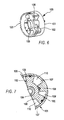
- Fig. 6 is a perspective view showing an example of a valve-timing controlling device 100 provided in a multilink-type variable expansion-ratio engine 10 according to a second embodiment.
- Fig. 7 is a cross-sectional view showing a relevant portion of the valve-timing controlling device 100.
- valve-timing controlling device 100 the device disclosed in Japanese Unexamined Patent Application Publication No. 2003-49616 may be used.
- the valve-timing controlling device 100 may be provided on a camshaft disposed at the exhaust side.
- the valve-timing controlling device may be used to control the opening/closing timing of the exhaust valve 61 by means of the controller 70.
- a valve-timing controlling device 100 will be described below in detail by reference to Figs. 6 and 7 .
- the valve-timing controlling device or adjuster (exhaust valve opening-timing adjusting means) 100 includes a cylindrical housing 101 serving as a first rotary member, a rotor 102 serving as a second rotary member housed in the housing 101, a hydraulic supply valve (not shown), and the controller 70 (not shown in Fig. 6 ) that controls the hydraulic supply valve.
- One end surface of the housing 101 has a cam sprocket wheel 103 fixed thereto.
- a timing chain (not shown) is wound between the cam sprocket wheel 103 and a crank sprocket wheel of the crankshaft 33 (not shown in Fig. 6 ).
- the rotor 102 is relatively rotatable with respect to the housing 101 by a predetermined angle.
- the rotor 102 is fixed to an end of a camshaft (not shown) which opens and closes the exhaust valve 61.
- the housing 101 rotates in synchronization with the crankshaft 33, and the rotor 102 rotates together with the housing 101, thereby driving the camshaft. From this predetermined state in which the camshaft is driven, the housing 101 and the rotor 102 rotate relatively respect to each other so as to advance or retard the phase of the camshaft with respect to the crankshaft 33.
- the housing 101 and the rotor 102 are disposed coaxially with respect to the center of rotation of the camshaft.
- the rotor 102 includes a plurality of vanes 105 that extend radially from the center of rotation of the rotor 102.
- three vanes 105 are provided in the rotor 102.
- the rotor 102 has an annular portion 106 extending along the inner periphery thereof, and the three vanes 105 extending from this annular portion 106 towards the housing 101 at a substantially fixed angular interval (120° in Figs. 6 and 7 ).
- the housing 101 has three projections 108 arranged on the inner surface thereof at a substantially fixed angular interval (120° in Fig. 7 ).
- Each of the projections 108 is projected towards the annular portion 106 of the rotor 102 and has an end that is in contact with the annular portion 106.
- Each adjacent pair of projections 108 has a fan-shaped recess 107 therebetween.
- the vanes 105 of the rotor 102 are disposed within these recesses 107. Since the circumferential length of each recess 107 is greater than the circumferential length of each vane 105, the rotor 102 is relatively rotatable with respect to the housing 101 in the circumferential direction by only a predetermined angle.
- Each of the recesses 107 is divided into two chambers by the corresponding vane 105. These two chambers function as pressure chambers, one being an advance hydraulic chamber 109 and the other being a retard hydraulic chamber 110. Accordingly, when the controller 70 controls the supply of oil pressure to the advance hydraulic chamber 109 through a hydraulic control valve, the rotor 102 rotates relatively in a direction for advancing the valve timing of the exhaust valve 61, namely, in the clockwise direction in Fig. 7 . On the other hand, when oil pressure is supplied to the retard hydraulic chamber 110, the rotor 102 rotates relatively in a direction for retarding the valve timing of the exhaust valve 61, namely, in the counterclockwise direction in Fig.
- this valve-timing controlling device 100 controls the valve timing of the exhaust valve 61 by adjusting the relative rotational position between the housing 101 and the rotor 102, the opening timing of the exhaust valve 61 is also advanced when the closing timing thereof is advanced. In other words, by correctively advancing the closing timing of the exhaust valve 61, the opening timing thereof is correctively advanced by the same corrected amount.
- the controller 70 controls the supply of oil pressure to the hydraulic chambers 109, 110 inside the housing 101 in accordance with the operating conditions of the multilink-type variable expansion-ratio engine 10. This control adjusts the relative rotational position between the housing 101 and the rotor 102, thereby controlling the valve timing of the exhaust valve 61.
- Fig. 8 illustrates another example of a valve-timing controlling device 200.
- Valve-timing controlling device 200 employs a mechanism disclosed in, for example, Japanese Unexamined Patent Application Publication No. 11-107725 . With reference to Figs. 8 and 9 , the following description is directed to a case where the valve-timing controlling device 200 is applied to an intake valve 212.
- the valve-timing controlling device or adjuster (exhaust valve opening-timing adjusting means) 200 includes a lift-amount controlling actuator 201 for controlling the lift amount of the intake valve 212, a phase-angle controlling actuator 202 for controlling the phase angle of the intake valve 212, and an engine controller 70 for controlling the lift-amount controlling actuator 201 and the phase-angle controlling actuator 202.
- the valve-timing controlling device 200 is equipped with the intake valve 212 disposed slidably on the cylinder head, a drive shaft 213 rotatably supported by an upper portion of the cylinder head, a drive cam 215 securely attached to the drive shaft 213, a control shaft 216 rotatably supported above the drive shaft 213, a rocker arm 218 rockably supported by the control shaft 216 with a control cam 217 disposed therebetween, and a rocking cam 220 disposed on an upper end of the intake valve 212 with a valve lifter 219 functioning as a transmission member therebetween. Furthermore, the drive cam 215 and the rocker arm 218 are linked to each other by means of a link arm 225, and the rocker arm 218 and the rocking cam 220 are linked to each other by means of a link member 226.
- the drive shaft 213 and the control shaft 216 are disposed parallel to a crankshaft (not shown).
- the drive shaft 213 has a driven sprocket wheel on one end thereof.
- the driven sprocket wheel transmits torque from the crankshaft 33 of the multilink-type variable expansion-ratio engine 10 to the drive shaft 213, thereby rotating the drive shaft 213.
- Fig. 9 illustrates the valve-timing controlling device 200 as viewed in a direction in which the drive shaft 213 extends.
- the rocker arm 218 has a base portion 218a in the central section thereof, which is rotatably supported by the control cam 217.
- a first end portion 218b of the rocker arm 218 extending from one side of the base portion 218a has a pinhole 218d in which a pin 221 is press-fitted.
- a second end portion 218c of the rocker arm 218 extending from the other side of the base portion 218a also has a pinhole 218e in which a pin 228 is press-fitted.
- the pin 228 is connected to a first end 226a of the link member 226.
- the control cam 217 is cylindrical and is fixed to the outer periphery of the control shaft 216.
- the center of axle P1 of the control cam 217 is biased from the center of axle P2 of the control shaft 216 by an amount ⁇ .
- the rocking cam 220 has a support hole 222a through which the drive shaft 213 extends, such that the drive shaft 213 is supported by the support hole 222a in a rotatable fashion.
- a cam-nose end 223 of the rocking cam 220 which is an end proximate to the second end portion 218c of the rocker arm 218, has a pinhole 223a.
- the lower side of the rocking cam 220 is defined by a circular base surface 224a and an arc cam surface 224b extending from the circular base surface 224a towards the cam-nose end 223.
- the circular base surface 224a and the arc cam surface 224b are contactable with the upper surface of the valve lifter 219 at a predetermined position thereof in accordance with the rocking position of the rocking cam 220.
- the link arm 225 includes an annular base portion 225a having a relatively large diameter and a protruding end 225b protruding from a specific position on the outer periphery surface of the base portion 225a.
- the base portion 225a has an engagement hole 225c in the center thereof.
- the engagement hole 225c is rotatably engaged to an outer periphery surface of a cam body 215a of the drive cam 215.
- the protruding end 225b has a pinhole 225d through which the pin 221 rotatably extends.
- the first and second ends 226a, 226b of the link member 226 have pin insertion holes 226c, 226d, respectively.
- An end of the pin 228 press-fitted in the pinhole 218e in the second end portion 218c of the rocker arm 218 extends rotatably through the pin insertion hole 226c, and likewise, an end of a pin 229 press-fitted in the pinhole 223a in the cam-nose end 223 of the rocking cam 220 extends rotatably through the pin insertion hole 226d.
- the link member 226 and the pins 228, 229 press-fitted in the respective pinholes 218e, 223a constitute a link mechanism.
- the control shaft 216 is rotated by the lift-amount controlling actuator 201 disposed at one end thereof within a predetermined rotation-angle range.
- the drive shaft 213 is rotated by the phase-angle controlling actuator 202 disposed at one end thereof within a predetermined rotation-angle range.
- the lift-amount controlling actuator 201 and the phase-angle controlling actuator 202 are driven based on a control signal from the controller 70, which detects the operating conditions of the engine 10.
- the controller 70 calculates the engine speed on the basis of a detection signal from a crank-angle sensor, calculates the load on the basis of a detection signal from an airflow meter, and detects the water temperature on the basis of a detection signal from a water temperature sensor. Based on the current operating conditions of the engine 10 determined from the above calculations and detection, the controller 70 outputs a control signal to the lift-amount controlling actuator 201 and the phase-angle controlling actuator 202.
- valve-timing controlling device 200 An operation of the valve-timing controlling device 200 will be described below with reference to Figs. 10A to 11B .
- the lift-amount controlling actuator 201 and the phase-angle controlling actuator 202 are rotated in one direction in response to a control signal from the controller 70.
- a thick portion 217a of the control cam 217 moves away from the drive shaft 213 in the upward direction. Consequently, in comparison to each of Figs.
- the rocker arm 218 is entirely shifted upward with respect to the drive shaft 213, and the cam-nose end 223 of the rocking cam 220 is forcibly lifted upward by a slight amount through the link member 226, whereby the entire device rotates clockwise.
- the lift-amount controlling actuator 201 and the phase-angle controlling actuator 202 are rotated in opposite directions in response to a control signal from the controller 70.
- the control shaft 216 rotates the control cam 217 clockwise from the position thereof shown in Figs. 10A and 10B , thus shifting the center of axle P1 (the thick portion 217a) downward. Consequently, in comparison to each of Figs.
- the rocker arm 218 entirely moves downward toward the drive shaft 213 such that the second end portion 218c of the rocker arm 218 pushes the cam-nose end 223 of the rocking cam 220 downward via the link member 226.
- the rocking cam 220 is entirely rotated counterclockwise by a predetermined amount.
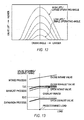
- Fig. 13 illustrates the relationship between the load of the multilink-type variable expansion-ratio engine 10 and the valve timing of the intake and exhaust valves.
- the opening timing of the exhaust valve 61 is controlled to a specific timing (i. e. , before the bottom dead center in the expansion process in Fig. 13 ) in view of attaining, for example, improved output and fuel consumption.
- the exhaust valve 61 is controlled so as to correctively advance the opening timing thereof.
- the opening timing of the exhaust valve 61 is adjusted to a timing that is advanced further from the bottom dead center in the expansion process so as to substantially lower the expansion ratio of the engine 10. In this case, the opening timing is advanced more as the engine load decreases.
- the expansion ratio becomes lower as the load decreases such as to reduce the occurrence of negative work, thereby achieving improved fuel consumption.
- the closing timing of the exhaust valve 61 is also advanced when the opening timing of the exhaust valve 61 is advanced.
- a control operation for advancing the opening timing of the intake valve 212 is also implemented.
- the valve overlap period between the intake and exhaust valves can be maintained, thereby preventing abnormal combustion caused by a change in the amount of internal EGR.
- the closing timing of the intake valve 212 is set to an advance-angle side of the bottom dead center of an intake process, and is set such as to be advanced more as the engine load decreases, thus acting as an intake-valve closing-timing adjusting mechanism.
- This valve-timing control operation for the intake valve 212 regulates the air intake so as to achieve less pumping loss and lower fuel consumption in comparison to an internal combustion engine that controls the air intake using a throttle valve.
- Fig. 14 is a flow chart illustrating the valve-timing control operation for the exhaust valve 61 performed by the controller 70.
- This control operation is a combination of the valve-timing control for the intake and exhaust valves described above and the variable expansion-ratio control of the multilink-type variable expansion-ratio engine 10 described in the first embodiment.
- this control operation corresponds to a case where the response of the valve-timing controlling device 100 for the exhaust valve 61 is substantially the same as the response of a variable expansion-ratio mechanism, which includes the control link 13 that changes the expansion ratio.
- step S1 a load is calculated on the basis of a detection signal of the airflow meter.
- step S2 the calculated load is compared with a predetermined load value. If the calculated load is below the predetermined load value, the operation proceeds to step S11. In step S11, since there is a possibility that negative work may occur in the latter half of an expansion process, the opening timing of the exhaust valve 61 is correctively advanced, and the operation ends. On the other hand, if the calculated load in step S2 is equal to or above the predetermined load value, the operation ends.
- the expansion-ratio control is implemented by prioritizing the valve-timing control for the exhaust valve 61.
- the expansion-ratio control based on the variable expansion-ratio mechanism may be implemented together with the valve-timing control.
- Fig. 15 is a P-V line diagram illustrating an Otto cycle in a case where the valve-timing control for the intake and exhaust valves illustrated in Figs. 13 and 14 is implemented.
- a solid line corresponds to a case where a load is equal to or above a predetermined load value
- a dotted line corresponds to a case where the variable expansion-ratio control for the intake and exhaust valves according to this embodiment is not implemented when a load is below the predetermined load value
- a dot-dash line corresponds to a case where the variable expansion-ratio control according to this embodiment is implemented when a load is below the predetermined load value.
- the load is controlled by regulating the air intake on the basis of the closing-timing control of the intake valve 212 as described in Fig. 13 .
- the pressure in the cylinder becomes a negative value since the exhaust valve 61 is closed in the latter half of an expansion process.
- the predetermined load value corresponds to a condition under which a negative pressure is generated in the latter half of an expansion process.
- the valve-timing controlling device 100 correctively advances the opening timing of the exhaust valve 61 in this embodiment to substantially lower the expansion ratio so as to reduce the occurrence of negative work.
- the dot-dash line corresponds to a case where the opening timing of the exhaust valve 61 is correctively advanced.
- the pressure in the cylinder 31a is maintained at the atmospheric pressure, whereby a negative pressure is not generated. Accordingly, this prevents the occurrence of negative work and thus avoids high fuel consumption.
- Figs. 16A to 16C illustrate a piston structure included in a multilink-type variable expansion-ratio engine 10 according to a third embodiment.
- Fig. 16A is a perspective view of the piston structure
- Fig. 16B is a cross-sectional view taken along line XVIB-XVIB in Fig. 16A
- Fig. 16C is a cross-sectional view taken along line XVIC-XVIC in Fig. 16A
- Figs. 17A and 17B illustrate the behavior of the piston 32.
- valve-timing controlling device 200 shown in Figs. 8 to 11 B is used in which the opening timing and the closing timing can be set independently. This will be described below in detail.
- the piston 32 in this embodiment is characterized in that a piston skirt 32a thereof is partly reduced in width by a significant amount.
- the piston 32 is constituted by a top portion 32b on which a piston ring is attached, and the piston skirt 32a disposed below the top portion 32b.
- the piston skirt 32a has its interference portion omitted, which interferes with a pair of counterweights 33c when the crankshaft 33 rotates.
- the piston 32 is configured such that when it is at the bottom dead center, the piston pin of the piston 32 is positioned between the pair of counterweights 33c (see Fig. 17A ). With the use of this piston 32, the piston stroke is made larger than the piston diameter, whereby the expansion ratio (compression ratio) can be increased.
- the lengths of the upper link 11, the lower link 12, and the control link 13 included in the multilink-type variable expansion-ratio engine 10 are modified and optimized from those in the first embodiment.
- the upper link 11 is given the minimum length possible to achieve an extended piston stroke.
- the engine stroke is extended to achieve a high expansion ratio.
- this structure also prevents the shape of the combustion chamber from being flat so as to avoid deterioration of the combustion state.
- the extended stroke allows for large displacement of the engine 10 without increasing the size of the engine, thereby attaining improved output.
- the engine size can be reduced so as to achieve weight reduction and improved layout inside the engine room.
- the upper link 11 can stand substantially orthogonally at the top dead center position of the piston 32 so that a load acting horizontally on the piston 32 (thrust load) can be reduced. Accordingly, this gives the piston skirt 32a sufficient strength.
- the valve-timing controlling device 200 for the intake and exhaust valves according to the third embodiment can control the opening timing and the closing timing in an independent fashion.
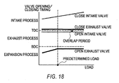
- Fig. 18 illustrates the relationship between the load of the multilink-type variable expansion-ratio engine 10 and the valve timing of the intake and exhaust valves when the valve-timing controlling device according to the third embodiment is used.
- the closing timing of the exhaust valve 61 is controlled to a specific timing just after the top dead center in the intake process regardless of the engine load.
- the opening timing of the exhaust valve 61 is controlled to a specific timing just before the bottom dead center in the expansion process.
- the opening timing of the exhaust valve 61 is correctively advanced from the bottom dead center. In this case, the opening timing is advanced more as the engine load decreases.
- the opening timing of the intake valve 212 is controlled to a specific timing just before the top dead center in the exhaust process regardless of the engine load. Consequently, the closing timing of the exhaust valve 61 and the opening timing of the intake valve 212 are fixedly set regardless of the load, and are set within the same valve overlap period, thereby preventing abnormal combustion caused by a change in the amount of internal EGR.
- Fig. 19 is a flow chart illustrating the valve-timing control operation for the exhaust valve 61 performed by the controller 70.
- This control operation may be a combination of the valve-timing control for the intake and exhaust valves described above and the variable expansion-ratio control of the multilink-type variable expansion-ratio engine 10 described in the first embodiment. In that case, the substantial setting range for the expansion ratio of the engine 10 can be further widened.
- this control operation corresponds to a case where the response of the valve-timing controlling device 100 for the exhaust valve 61 is slower than the response of the variable expansion-ratio mechanism which includes the control link 13 that changes the expansion ratio.
- the response of the variable expansion-ratio mechanism is given a higher priority, such that the expansion-ratio control based on the variable expansion-ratio mechanism is performed first, and the expansion-ratio control based on the valve-timing control of the intake and exhaust values with the slower response is performed afterwards.
- Prioritizing the control operation having better response can avoid high fuel consumption caused by slow response.
- step S1 a load is calculated on the basis of a detection signal of the airflow meter.
- step S2 the calculated load is compared with a predetermined load value. If the calculated load is below the predetermined load value, the operation proceeds to step S21.
- step S21 the variable expansion-ratio control is performed such as to lower the expansion ratio.
- step S11 since there is a possibility that negative work may occur in the latter half of an expansion process, the opening timing of the exhaust valve 61 is correctively advanced.
- step S22 the variable expansion-ratio control is performed such as to increase the expansion ratio, and the operation ends.
- the calculated load in step S2 is equal to or above the predetermined load value, the operation ends.
Landscapes
- Engineering & Computer Science (AREA)
- Mechanical Engineering (AREA)
- General Engineering & Computer Science (AREA)
- Chemical & Material Sciences (AREA)
- Combustion & Propulsion (AREA)
- Output Control And Ontrol Of Special Type Engine (AREA)
- Shafts, Cranks, Connecting Bars, And Related Bearings (AREA)
- Transmission Devices (AREA)
- Valve Device For Special Equipments (AREA)
Claims (13)
- Vorrichtung zum Steuern eines Motors, die Folgendes umfasst:Expansionsverhältnis-Einstellmittel (11, 12, 13) zum Einstellen eines Expansionsverhältnisses;Lasterkennungsmittel (S1) zum Erkennen einer Motorlast; undSteuerungsmittel (70) zum Steuern des Expansionsverhältnis-Einstellmittels (11, 12, 13) auf der Basis der vom Lasterkennungsmittel (S1) erkannten Motorlast derart, dass das Expansionsverhältnis zu der Zeit, zu der die Last unter einem vorherbestimmten Lastwert ist, niedriger eingestellt ist als zu der Zeit, zu der die Last gleich dem vorherbestimmten Lastwert ist;dadurch gekennzeichnet, dass der vorherbestimmte Lastwert ein Lastwert ist, bei dem ein Druck in einem Zylinder unter den Atmosphärendruck sinkt, bevor ein Auslassventil (61) in einer zweiten Hälfte eines Expansionsprozesses öffnet.
- Vorrichtung nach Anspruch 1, wobei das Steuerungsmittel (70) dazu angeordnet ist, das Expansionsverhältnis-Einstellmittel (11, 12, 13) derart zu steuern, dass das Expansionsverhältnis zu der Zeit, zu der die Last unter dem vorherbestimmten Lastwert ist, mit abnehmender Last geringer wird.
- Vorrichtung nach einem der vorangehenden Ansprüche, wobei das Expansionsverhältnis-Einstellmittel (11, 12, 13) Auslassventil-Öffnungszeitpunkt-Einstellmittel zum Einstellen eines Öffnungszeitpunkts eines Auslassventils (61) umfasst und wobei, wenn die Last unter dem vorherbestimmten Lastwert ist, das Steuerungsmittel (70) den Öffnungszeitpunkt des Auslassventils (61) vorstellt, um das Expansionsverhältnis zu verringern.
- Vorrichtung nach Anspruch 3, wobei das Auslassventil-Öffnungszeitpunkt-Einstellmittel (70) dazu angeordnet ist, nur den Öffnungszeitpunkt des Auslassventils (61) einzustellen.
- Vorrichtung nach Anspruch 3, wobei das Auslassventil-Öffnungszeitpunkt-Einstellmittel (70) dazu angeordnet ist, einen Schließzeitpunkt des Auslassventils (61) um den vorgestellten Betrag des Öffnungszeitpunkts des Auslassventils (61) vorzustellen.
- Vorrichtung nach Anspruch 5, wobei das Expansionsverhältnis-Einstellmittel (11, 12, 13) Einlassventil-Öffnungszeitpunkt-Einstellmittel zum Einstellen eines Offnungszeitpunkts eines Einlassventils (212) umfasst und wobei, wenn die Last unter dem vorherbestimmten Lastwert ist, das Steuerungsmittel (70) dazu angeordnet ist, den Öffnungszeitpunkt des Einlassventils (212) zusammen mit dem Vorstellen des Öffnungs- und des Schließzeitpunkts des Auslassventils (61) vorzustellen.
- Vorrichtung nach einem der vorangehenden Ansprüche, wobei das Expansionsverhältnis-Einstellmittel (11, 12, 13) ein Einstellmittel für den oberen Totpunkt zum Einstellen eines oberen Totpunkts eines Kolbens (32) umfasst und wobei, wenn die Last unter dem vorherbestimmten Lastwert ist, das Steuerungsmittel (70) den oberen Totpunkt des Kolbens (32) absenkt, um das Expansionsverhältnis zu verringern.
- Vorrichtung nach Anspruch 7, wobei das Einstellmittel für den oberen Totpunkt eine Vielzahl von Verbindungsgliedern umfasst, die den Kolben (32) mit einer Kurbelwelle (25) verbinden und wobei das Expansionsverhältnis verringert wird, indem die Bewegung mindestens eines der Verbindungsglieder reguliert wird.
- Vorrichtung nach Anspruch 8, wobei die Vielzahl von Verbindungsgliedern Folgendes umfasst:ein erstes Verbindungsglied (11), das mittels eines Kolbenbolzens mit dem Kolben (32) verbunden ist;ein zweites Verbindungsglied (12), das kippbar mit dem ersten Verbindungsglied (11) und drehbar mit der Kurbelwelle (25) verbunden ist; undein drittes Verbindungsglied (13), das kippbar mit dem zweiten Verbindungsglied (12) verbunden ist und das Kippen des zweiten Verbindungsglieds (12) reguliert.
- Vorrichtung nach einem der Ansprüche 7 bis 9, wobei der Kolben (32) Hubcharakteristika hat, bei denen es sich im Wesentlichen um eine einfache harmonische Bewegung handelt.
- Vorrichtung nach einem der Ansprüche 7 bis 10, wobei ein Hubbetrag des Kolbens (32) größer ist als der Durchmesser des Kolbens.
- Verfahren zum Steuern eines Motors, das Folgendes umfasst:Erkennen einer Motorlast; undSteuern eines Expansionsverhältnisses des Motors auf der Basis des Erkennungsschritts derart, dass das Expansionsverhältnis zu der Zeit, zu der die Last unter einem vorherbestimmten Wert ist, niedriger eingestellt wird als zu der Zeit, zu der die Last mindestens gleich dem vorherbestimmten Lastwert ist;dadurch gekennzeichnet, dass der vorherbestimmte Lastwert ein Lastwert ist, bei dem ein Druck in einem Zylinder unter den Atmosphärendruck sinkt, bevor ein Auslassventil (61) in einer zweiten Hälfte eines Expansionsprozesses öffnet.
- Motor oder Fahrzeug mit einer Vorrichtung nach einem der vorangehenden Ansprüche oder das dazu ausgebildet ist, ein Verfahren nach einem der vorangehenden Ansprüche zu nutzen.
Applications Claiming Priority (2)
| Application Number | Priority Date | Filing Date | Title |
|---|---|---|---|
| JP2006067855 | 2006-03-13 | ||
| JP2006329864A JP5114046B2 (ja) | 2006-03-13 | 2006-12-06 | 可変膨張比エンジン |
Publications (3)
| Publication Number | Publication Date |
|---|---|
| EP1835151A2 EP1835151A2 (de) | 2007-09-19 |
| EP1835151A3 EP1835151A3 (de) | 2007-11-14 |
| EP1835151B1 true EP1835151B1 (de) | 2009-06-10 |
Family
ID=38158042
Family Applications (1)
| Application Number | Title | Priority Date | Filing Date |
|---|---|---|---|
| EP07103901A Expired - Fee Related EP1835151B1 (de) | 2006-03-13 | 2007-03-11 | Motorsteuerung |
Country Status (4)
| Country | Link |
|---|---|
| US (1) | US7334547B2 (de) |
| EP (1) | EP1835151B1 (de) |
| JP (1) | JP5114046B2 (de) |
| DE (1) | DE602007001251D1 (de) |
Families Citing this family (17)
| Publication number | Priority date | Publication date | Assignee | Title |
|---|---|---|---|---|
| JP2007303423A (ja) * | 2006-05-12 | 2007-11-22 | Toyota Motor Corp | 火花点火式内燃機関 |
| JP4882912B2 (ja) * | 2007-08-10 | 2012-02-22 | 日産自動車株式会社 | 可変圧縮比内燃機関 |
| JP4725561B2 (ja) | 2007-08-13 | 2011-07-13 | トヨタ自動車株式会社 | 火花点火式内燃機関 |
| JP4528813B2 (ja) * | 2007-09-10 | 2010-08-25 | 日立オートモティブシステムズ株式会社 | 筒内噴射型内燃機関の制御装置 |
| US7980207B2 (en) * | 2007-10-26 | 2011-07-19 | Nissan Motor Co., Ltd. | Multi-link engine |
| US7597071B1 (en) * | 2008-06-10 | 2009-10-06 | Gene Hirs | Apparatus and method for establishing dual compression ratios within an internal combustion engine to improve mileage |
| US7891334B2 (en) * | 2008-07-17 | 2011-02-22 | O'leary Paul W | Engine with variable length connecting rod |
| IT1392369B1 (it) * | 2008-12-19 | 2012-02-28 | Innovative Technological Systems Di Fontana Claudio Ditta Individuale | Motore a combustione esterna |
| CN101861452B (zh) * | 2009-01-29 | 2013-02-27 | 丰田自动车株式会社 | 高膨胀比内燃机 |
| US8176888B2 (en) * | 2011-02-14 | 2012-05-15 | Ford Global Technologies, Llc | Method for starting a mixed fuel engine |
| JP5888108B2 (ja) * | 2012-05-18 | 2016-03-16 | 日産自動車株式会社 | 可変圧縮比内燃機関 |
| JP6564652B2 (ja) * | 2015-09-03 | 2019-08-21 | 日立オートモティブシステムズ株式会社 | 内燃機関の圧縮比調整装置及び内燃機関の圧縮比調整装置の制御方法 |
| JP6519598B2 (ja) * | 2017-01-11 | 2019-05-29 | トヨタ自動車株式会社 | 内燃機関の制御装置 |
| CN110671197B (zh) * | 2018-12-29 | 2021-08-20 | 长城汽车股份有限公司 | 发动机及具有其的车辆 |
| CN110671199B (zh) * | 2018-12-30 | 2021-07-06 | 长城汽车股份有限公司 | 可变压缩比机构与发动机 |
| CN110657024A (zh) * | 2018-12-30 | 2020-01-07 | 长城汽车股份有限公司 | 可变压缩比机构与发动机 |
| US10927754B2 (en) * | 2019-01-28 | 2021-02-23 | International Engine Intellectual Property Company, Llc | Engine having a variable compression ratio |
Family Cites Families (16)
| Publication number | Priority date | Publication date | Assignee | Title |
|---|---|---|---|---|
| GB746800A (en) * | 1954-03-05 | 1956-03-21 | English Electric Co Ltd | Improvements in and relating to pressure charged internal combustion engines |
| GB2267310B (en) * | 1992-05-27 | 1996-04-24 | Fuji Heavy Ind Ltd | System for controlling a valve mechanism for an internal combustion engine |
| JPH08177429A (ja) | 1994-12-20 | 1996-07-09 | Mitsubishi Motors Corp | 可変バルブタイミング機構 |
| JP3629879B2 (ja) * | 1997-03-13 | 2005-03-16 | トヨタ自動車株式会社 | 圧縮点火式内燃機関 |
| JP3881783B2 (ja) | 1997-08-07 | 2007-02-14 | 株式会社日立製作所 | 内燃機関の可変動弁装置 |
| JP2000073804A (ja) | 1998-09-01 | 2000-03-07 | Toyota Autom Loom Works Ltd | 内燃機関及びその制御装置 |
| JP3979081B2 (ja) * | 2001-01-16 | 2007-09-19 | 日産自動車株式会社 | 内燃機関の燃焼制御システム |
| JP3849443B2 (ja) | 2001-03-28 | 2006-11-22 | 日産自動車株式会社 | 内燃機関のピストン駆動装置 |
| JP2003049616A (ja) | 2001-08-07 | 2003-02-21 | Nissan Motor Co Ltd | 内燃機関のバルブタイミング制御装置 |
| US6814032B2 (en) * | 2001-12-25 | 2004-11-09 | Niigata Power Systems Co., Ltd. | Dual fuel engine |
| JP4416377B2 (ja) * | 2002-05-16 | 2010-02-17 | 日産自動車株式会社 | 内燃機関の制御装置 |
| JP4151395B2 (ja) * | 2002-11-29 | 2008-09-17 | 三菱自動車工業株式会社 | 高膨張比サイクルエンジン |
| JP2005147339A (ja) * | 2003-11-19 | 2005-06-09 | Nissan Motor Co Ltd | 筒内直接噴射式ディーゼル機関 |
| US6918384B2 (en) * | 2003-12-08 | 2005-07-19 | General Motors Corporation | Diesel engine with cam phasers for in-cylinder temperature control |
| WO2006023098A2 (en) * | 2004-07-26 | 2006-03-02 | General Motors Corporation | NOx EMISSION CONTROL FOR A CONTROLLED AUTO-IGNITION FOUR-SRTOKE INTERNAL COMBUSTION ENGINE |
| JP4466361B2 (ja) * | 2004-12-24 | 2010-05-26 | 日産自動車株式会社 | 内燃機関 |
-
2006
- 2006-12-06 JP JP2006329864A patent/JP5114046B2/ja not_active Expired - Fee Related
-
2007
- 2007-03-11 EP EP07103901A patent/EP1835151B1/de not_active Expired - Fee Related
- 2007-03-11 DE DE602007001251T patent/DE602007001251D1/de active Active
- 2007-03-12 US US11/716,886 patent/US7334547B2/en active Active
Also Published As
| Publication number | Publication date |
|---|---|
| DE602007001251D1 (de) | 2009-07-23 |
| US20070209630A1 (en) | 2007-09-13 |
| US7334547B2 (en) | 2008-02-26 |
| EP1835151A3 (de) | 2007-11-14 |
| JP2007278272A (ja) | 2007-10-25 |
| JP5114046B2 (ja) | 2013-01-09 |
| EP1835151A2 (de) | 2007-09-19 |
Similar Documents
| Publication | Publication Date | Title |
|---|---|---|
| EP1835151B1 (de) | Motorsteuerung | |
| KR101169856B1 (ko) | 가변 밸브 기어를 구비한 내연 기관 | |
| KR101396736B1 (ko) | 가변 밸브 기어를 구비한 내연 기관 | |
| US7779796B2 (en) | Variable valve actuating apparatus for internal combustion engine and process of controlling the same | |
| EP1288453B1 (de) | Variabler Ventiltrieb einer Brennkraftmaschine zur Hub- und Phasenvariation der Ventile | |
| US6705257B2 (en) | Apparatus and method for controlling variable valve in internal combustion engine | |
| US8006658B2 (en) | Variable valve actuation apparatus of internal combustion engine | |
| US7481199B2 (en) | Start control apparatus of internal combustion engine | |
| US20070074687A1 (en) | Variable valve lift control system for a combustion engine with underneath camshaft | |
| JP2003035111A (ja) | 内燃機関 | |
| US6990937B2 (en) | Variable valve control system and method for an internal combustion engine | |
| JP2007239555A (ja) | 内燃機関 | |
| JP6564652B2 (ja) | 内燃機関の圧縮比調整装置及び内燃機関の圧縮比調整装置の制御方法 | |
| US7513228B2 (en) | Internal combustion engine | |
| US8844481B2 (en) | Variable valve apparatus for internal combustion engine | |
| US20020007808A1 (en) | Internal combustion engine variable valve characteristic control apparatus and three-dimensional cam | |
| JP4345197B2 (ja) | 内燃機関のノッキング制御装置 | |
| JP4622431B2 (ja) | エンジンの可変動弁装置 | |
| JP3797083B2 (ja) | 内燃機関の可変動弁装置 | |
| JP4325525B2 (ja) | 可変動弁機構 | |
| JP2021021346A (ja) | 内燃機関の可変圧縮比システム | |
| KR20140123429A (ko) | 내연 기관의 가변 밸브 작동 장치 | |
| JP2005076466A (ja) | エンジンの制御装置 | |
| JP5012565B2 (ja) | 内燃機関の制御方法および内燃機関システム | |
| JP5310207B2 (ja) | 内燃機関の動弁システム |
Legal Events
| Date | Code | Title | Description |
|---|---|---|---|
| PUAI | Public reference made under article 153(3) epc to a published international application that has entered the european phase |
Free format text: ORIGINAL CODE: 0009012 |
|
| AK | Designated contracting states |
Kind code of ref document: A2 Designated state(s): AT BE BG CH CY CZ DE DK EE ES FI FR GB GR HU IE IS IT LI LT LU LV MC MT NL PL PT RO SE SI SK TR |
|
| AX | Request for extension of the european patent |
Extension state: AL BA HR MK YU |
|
| PUAL | Search report despatched |
Free format text: ORIGINAL CODE: 0009013 |
|
| AK | Designated contracting states |
Kind code of ref document: A3 Designated state(s): AT BE BG CH CY CZ DE DK EE ES FI FR GB GR HU IE IS IT LI LT LU LV MC MT NL PL PT RO SE SI SK TR |
|
| AX | Request for extension of the european patent |
Extension state: AL BA HR MK YU |
|
| RIC1 | Information provided on ipc code assigned before grant |
Ipc: F01L 13/08 20060101ALI20070625BHEP Ipc: F02D 15/02 20060101AFI20071006BHEP |
|
| 17P | Request for examination filed |
Effective date: 20080514 |
|
| 17Q | First examination report despatched |
Effective date: 20080616 |
|
| AKX | Designation fees paid |
Designated state(s): DE FR GB |
|
| GRAP | Despatch of communication of intention to grant a patent |
Free format text: ORIGINAL CODE: EPIDOSNIGR1 |
|
| GRAS | Grant fee paid |
Free format text: ORIGINAL CODE: EPIDOSNIGR3 |
|
| GRAA | (expected) grant |
Free format text: ORIGINAL CODE: 0009210 |
|
| AK | Designated contracting states |
Kind code of ref document: B1 Designated state(s): DE FR GB |
|
| REG | Reference to a national code |
Ref country code: GB Ref legal event code: FG4D |
|
| REF | Corresponds to: |
Ref document number: 602007001251 Country of ref document: DE Date of ref document: 20090723 Kind code of ref document: P |
|
| PLBE | No opposition filed within time limit |
Free format text: ORIGINAL CODE: 0009261 |
|
| STAA | Information on the status of an ep patent application or granted ep patent |
Free format text: STATUS: NO OPPOSITION FILED WITHIN TIME LIMIT |
|
| 26N | No opposition filed |
Effective date: 20100311 |
|
| REG | Reference to a national code |
Ref country code: FR Ref legal event code: PLFP Year of fee payment: 10 |
|
| REG | Reference to a national code |
Ref country code: FR Ref legal event code: PLFP Year of fee payment: 11 |
|
| REG | Reference to a national code |
Ref country code: FR Ref legal event code: PLFP Year of fee payment: 12 |
|
| PGFP | Annual fee paid to national office [announced via postgrant information from national office to epo] |
Ref country code: GB Payment date: 20220120 Year of fee payment: 16 Ref country code: DE Payment date: 20220118 Year of fee payment: 16 |
|
| PGFP | Annual fee paid to national office [announced via postgrant information from national office to epo] |
Ref country code: FR Payment date: 20220118 Year of fee payment: 16 |
|
| REG | Reference to a national code |
Ref country code: DE Ref legal event code: R119 Ref document number: 602007001251 Country of ref document: DE |
|
| GBPC | Gb: european patent ceased through non-payment of renewal fee |
Effective date: 20230311 |
|
| PG25 | Lapsed in a contracting state [announced via postgrant information from national office to epo] |
Ref country code: GB Free format text: LAPSE BECAUSE OF NON-PAYMENT OF DUE FEES Effective date: 20230311 |
|
| PG25 | Lapsed in a contracting state [announced via postgrant information from national office to epo] |
Ref country code: GB Free format text: LAPSE BECAUSE OF NON-PAYMENT OF DUE FEES Effective date: 20230311 Ref country code: FR Free format text: LAPSE BECAUSE OF NON-PAYMENT OF DUE FEES Effective date: 20230331 Ref country code: DE Free format text: LAPSE BECAUSE OF NON-PAYMENT OF DUE FEES Effective date: 20231003 |