EP1834665B1 - Ventilverbinder für medizinische Leitungen - Google Patents
Ventilverbinder für medizinische Leitungen Download PDFInfo
- Publication number
- EP1834665B1 EP1834665B1 EP07104236A EP07104236A EP1834665B1 EP 1834665 B1 EP1834665 B1 EP 1834665B1 EP 07104236 A EP07104236 A EP 07104236A EP 07104236 A EP07104236 A EP 07104236A EP 1834665 B1 EP1834665 B1 EP 1834665B1
- Authority
- EP
- European Patent Office
- Prior art keywords
- elastic
- tubular body
- valve connector
- connector according
- sealing member
- Prior art date
- Legal status (The legal status is an assumption and is not a legal conclusion. Google has not performed a legal analysis and makes no representation as to the accuracy of the status listed.)
- Active
Links
Images


Classifications
-
- A—HUMAN NECESSITIES
- A61—MEDICAL OR VETERINARY SCIENCE; HYGIENE
- A61M—DEVICES FOR INTRODUCING MEDIA INTO, OR ONTO, THE BODY; DEVICES FOR TRANSDUCING BODY MEDIA OR FOR TAKING MEDIA FROM THE BODY; DEVICES FOR PRODUCING OR ENDING SLEEP OR STUPOR
- A61M39/00—Tubes, tube connectors, tube couplings, valves, access sites or the like, specially adapted for medical use
- A61M39/22—Valves or arrangement of valves
- A61M39/26—Valves closing automatically on disconnecting the line and opening on reconnection thereof
-
- A—HUMAN NECESSITIES
- A61—MEDICAL OR VETERINARY SCIENCE; HYGIENE
- A61M—DEVICES FOR INTRODUCING MEDIA INTO, OR ONTO, THE BODY; DEVICES FOR TRANSDUCING BODY MEDIA OR FOR TAKING MEDIA FROM THE BODY; DEVICES FOR PRODUCING OR ENDING SLEEP OR STUPOR
- A61M39/00—Tubes, tube connectors, tube couplings, valves, access sites or the like, specially adapted for medical use
- A61M39/02—Access sites
- A61M39/04—Access sites having pierceable self-sealing members
- A61M39/045—Access sites having pierceable self-sealing members pre-slit to be pierced by blunt instrument
-
- A—HUMAN NECESSITIES
- A61—MEDICAL OR VETERINARY SCIENCE; HYGIENE
- A61M—DEVICES FOR INTRODUCING MEDIA INTO, OR ONTO, THE BODY; DEVICES FOR TRANSDUCING BODY MEDIA OR FOR TAKING MEDIA FROM THE BODY; DEVICES FOR PRODUCING OR ENDING SLEEP OR STUPOR
- A61M39/00—Tubes, tube connectors, tube couplings, valves, access sites or the like, specially adapted for medical use
- A61M39/10—Tube connectors; Tube couplings
-
- A—HUMAN NECESSITIES
- A61—MEDICAL OR VETERINARY SCIENCE; HYGIENE
- A61M—DEVICES FOR INTRODUCING MEDIA INTO, OR ONTO, THE BODY; DEVICES FOR TRANSDUCING BODY MEDIA OR FOR TAKING MEDIA FROM THE BODY; DEVICES FOR PRODUCING OR ENDING SLEEP OR STUPOR
- A61M39/00—Tubes, tube connectors, tube couplings, valves, access sites or the like, specially adapted for medical use
- A61M2039/0036—Tubes, tube connectors, tube couplings, valves, access sites or the like, specially adapted for medical use characterised by a septum having particular features, e.g. having venting channels or being made from antimicrobial or self-lubricating elastomer
-
- A—HUMAN NECESSITIES
- A61—MEDICAL OR VETERINARY SCIENCE; HYGIENE
- A61M—DEVICES FOR INTRODUCING MEDIA INTO, OR ONTO, THE BODY; DEVICES FOR TRANSDUCING BODY MEDIA OR FOR TAKING MEDIA FROM THE BODY; DEVICES FOR PRODUCING OR ENDING SLEEP OR STUPOR
- A61M39/00—Tubes, tube connectors, tube couplings, valves, access sites or the like, specially adapted for medical use
- A61M39/10—Tube connectors; Tube couplings
- A61M2039/1033—Swivel nut connectors, e.g. threaded connectors, bayonet-connectors
-
- A—HUMAN NECESSITIES
- A61—MEDICAL OR VETERINARY SCIENCE; HYGIENE
- A61M—DEVICES FOR INTRODUCING MEDIA INTO, OR ONTO, THE BODY; DEVICES FOR TRANSDUCING BODY MEDIA OR FOR TAKING MEDIA FROM THE BODY; DEVICES FOR PRODUCING OR ENDING SLEEP OR STUPOR
- A61M39/00—Tubes, tube connectors, tube couplings, valves, access sites or the like, specially adapted for medical use
- A61M39/22—Valves or arrangement of valves
- A61M39/26—Valves closing automatically on disconnecting the line and opening on reconnection thereof
- A61M2039/263—Valves closing automatically on disconnecting the line and opening on reconnection thereof where the fluid space within the valve is decreasing upon disconnection
-
- A—HUMAN NECESSITIES
- A61—MEDICAL OR VETERINARY SCIENCE; HYGIENE
- A61M—DEVICES FOR INTRODUCING MEDIA INTO, OR ONTO, THE BODY; DEVICES FOR TRANSDUCING BODY MEDIA OR FOR TAKING MEDIA FROM THE BODY; DEVICES FOR PRODUCING OR ENDING SLEEP OR STUPOR
- A61M39/00—Tubes, tube connectors, tube couplings, valves, access sites or the like, specially adapted for medical use
- A61M39/22—Valves or arrangement of valves
- A61M39/26—Valves closing automatically on disconnecting the line and opening on reconnection thereof
- A61M2039/267—Valves closing automatically on disconnecting the line and opening on reconnection thereof having a sealing sleeve around a tubular or solid stem portion of the connector
Definitions
- the present invention relates to valve connectors for medical lines, for example lines for infusion by means of an introducer for introducing a fluid infusion substance, typically a luer connector or luer-lock connector, for example of a needleless syringe.
- a fluid infusion substance typically a luer connector or luer-lock connector, for example of a needleless syringe.
- Valve connectors of this type are known, for example, from the documents Nos. US-5242342 , US-5676346 , US-6706022 , US-5700248 and US-6682509 .
- a valve connector according to the preamble of Claim 1, in which a tubular body is provided having a cavity, an inlet end provided for engagement of an introducer of liquid, and an outlet end.
- a hollow spike is set axially within the cavity of the tubular body and has a closed tip facing the inlet end of the tubular body and set at an axial distance from this.
- the hollow spike is in communication with the outlet end of the tubular body and has at least one side hole set at a distance from its closed tip for communication with the cavity of the tubular body.
- the connector moreover includes an elastic sealing member, which comprises an elastic head having a pre-slit and normally set in a condition of closing (or deactivated condition) within the inlet end of the tubular body, in which the pre-slit is closed.
- the elastic head is displaceable axially against the closed tip of the hollow spike as a result of insertion of the introducer into the inlet end of the tubular body in order to interact with said tip, assuming an elastically deformed configuration of opening (activated condition), in which the pre-slit opens.
- the sealing member of the valve connector moreover includes an elastic hollow element joined to the head, set between the tubular body and the hollow spike and having sealing means in contact with said hollow spike for isolating the aforesaid at least one side hole from the cavity of the tubular body when the head is set in the undeformed condition of closing.
- the elastic hollow element includes an elastic thrust means, which tends to maintain the head of the sealing member in the aforesaid condition of closing.
- Valve connectors of the above type must meet a series of fundamental requisites, since their use is frequently critical for survival of patients that make use thereof.
- closing of the inlet end of the tubular body performed by the head of the sealing member must be substantially fluid-tight so as to ensure a total anti-bacterial barrier, even following upon repeated opening and re-closing of the valve connector.
- these connectors In the third place, these connectors must be able to support effectively possible overpressures that may be generated inside them in use, and in the condition of closing (or deactivated condition) guarantee an effective fluid-tightness at positive and negative pressures.
- valve connectors must be easily cleanable and disinfectable (“swabbable”) at the inlet end, typically using a swab soaked in disinfectant.
- valve connectors known from the aforementioned documents Nos. US-5700248 and US-6682509
- opening of the communication between the inlet end of the tubular body and the outlet end, through the side hole or holes of the hollow spike at the moment of engagement of the introducer, is performed following upon traversal of the pre-slit of the elastic head by the tip of the hollow spike.
- the closed tip of the hollow spike is, instead, shaped so as to cause the head of the sealing member to assume the aforesaid configuration of opening, without traversal of the pre-slit.
- the elastic thrust means of the elastic hollow element of the sealing member typically has a corrugated or bellows- like wall, so that axial compression thereof produces a collapse like that of a concertina, or else an uncorrugated, but in any case axially collapsible, wall.
- the axial compression or collapse of the elastic hollow element causes the elastic head of the sealing member to slide along the hollow spike until the corresponding sealing means open the communication between the cavity of the tubular body and the side hole or holes of the hollow spike, i.e., between the inlet end and the outlet end of the tubular body.
- the elastic thrust means of the sealing member comprises a base part of said elastic hollow element having a generally cylindrical axial wall, set at a radial distance from said spike so as to define with this an annular chamber, said base part being joined to said elastic hollow element through a generally transverse annular wall, which, during the axial displacement of the elastic head from the condition of closing to the condition of opening, bends within said annular chamber.
- the aforesaid generally transverse wall bends, undergoing deformation due to tensile stress.
- valve connector according to the invention presents an improved degree of reliability, guaranteeing a prompt return of the sealing member to the closed condition even following upon repeated opening, with appreciably reduced overall axial dimensions of the connector.
- the valve connector is made up of a minimal number of parts, and hence can be produced in a relatively simple and inexpensive way, and moreover - thanks to further solutions that will be clarified in what follows - is able to ensure substantial absence of overpressures or negative pressure inside it during the steps of transition between the condition of opening and that of closing.
- the tubular body of the connector according to the invention is advantageously formed with a tubular side wye connector.
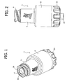
- the first embodiment of the valve connector for medical infusion lines basically comprises three components: an external tubular body 1, an internal hollow spike 2, set axially within the cavity of the tubular body 1, and an elastic sealing member 3.
- the tubular body 1 and the hollow spike 2 are made of rigid moulded plastic material, whilst the sealing member 3 is made of an elastic material, for example silicone rubber.
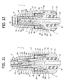
- the tubular body 1 has an inlet end 4 formed like a female luer-lock connection member for engagement, in a generally conventional way, with a male luer-lock connection member of an introducer for fluid, constituted, for example, by a needleless syringe, a part of which is designated as a whole by S in Figures 3 and 11 .
- the inlet end 4 is connected to a generally cylindrical intermediate portion 5, followed by a final widened portion 6, which is also generally cylindrical.
- the internal surface of the inlet end 4 has an initial cylindrical part 7 formed with a series of axial channels 8 and radiused to a portion having the shape of a truncated cone 9.
- the internal surface of the intermediate part 5 has, in succession, towards the final portion 6, a first cylindrical portion 10, a portion having the shape of a truncated cone 11, a second cylindrical portion 12, a portion having the shape of a truncated cone 13, a third cylindrical portion 14, a portion having the shape of a truncated cone 15, and a fourth cylindrical portion 16 terminating with a ring of front axial projections 17 facing the inside of the enlarged terminal portion 6.
- the internal surface of the latter is in turn formed with a ring of axial projections 18 projecting radially, the free ends of which define an annular shoulder designated by 27, the function of which will be clarified in what follows.
- the cavity of the tubular body 1 is designated as a whole by 19.
- the hollow spike 2 illustrated in greater detail in Figure 16 , has a base designated as a whole by 20, formed on the outside with a gripping ring 21 and shaped internally like a male luer-lock connection member with a central tubular shank 22 having a slightly conical outer surface and an internally threaded external shell 23.
- the connection member 22-23 defines the outlet end of the valve connector 1, designated as a whole by 24.
- the base 20 is formed with a first annular flange 25 of larger diameter, for joining the edge of the free end of the widened terminal portion 6 of the tubular body 1, fixed in the way represented in Figures 3-12 , and an annular flange of smaller diameter 26, the function of which will also be clarified in what follows.
- Branching off in an integral way from said annular flange 26 is a tubular post 28, preferably but not necessarily coaxial to the shank 22 and in communication with this, including an initial portion within a conical surface 29, divergent towards the outlet end 24 of the connector, followed by a cylindrical portion 30 formed with one, two or more side holes 31, for example in the form of axially elongated slots.
- the cylindrical portion 30 has, at its free end, a closed tip 32 (clearly visible in Figures 3 to 12 ) facing the inlet end 4 of the tubular body 1 and situated at a certain axial distance therefrom.
- a closed tip 32 (clearly visible in Figures 3 to 12 ) facing the inlet end 4 of the tubular body 1 and situated at a certain axial distance therefrom.
- Projecting from the closed tip 32 is a ring of radial axial projections 33 set at angular distances apart so as to define between them axial-radial channels of flow 34.
- the end surfaces of the projections 33 facing the inlet end 4 are preferably plane or slightly rounded.
- a conical annular surface 32a Formed underneath the closed tip 32 is a conical annular surface 32a.
- the sealing member 3 is illustrated in detail in Figures 17 to 19 . It comprises, in a single piece, an elastic head 35, an elastic hollow element 36, and an elastic base 37.
- the general shape of the sealing member 3, and in particular its external conformation, corresponds substantially to that of the cavity 19 of the tubular body 1, within which it is housed.
- the elastic head 35 has a cylindrical outer surface complementary to the internal surface 7 of the inlet end 4 in such a way as to enable housing thereof, in the way represented in Figures 3 and 4 , with slight radial play, i.e., without substantial interference, in a condition of closing in which said head 35 is substantially undeformed.
- a pre-slit or axial notch 38 Formed through the head 35 is a pre-slit or axial notch 38, which, in the undeformed condition of closing of the elastic head 35 within the inlet end 4, is maintained gripped as a result of the elasticity of the head 35.
- an anti-bacterial protection barrier is formed between the inside of the valve connector and the outside, ensuring at the time same the possibility of an effective cleaning conventionally performed by means of a swab soaked in a disinfectant.
- the head 35 is connected to the elastic hollow element 36 through a portion having the shape of a truncated cone 39, complementary to the conical surface 9 of the tubular body 1.
- the outer surface of the elastic hollow element 36 in turn has a first cylindrical portion 40, which is radiused to a second cylindrical portion 41 through a portion having the shape of a truncated cone 42.
- the second cylindrical portion 41 is radiused in turn to the elastic base 37 through a portion having the shape of a truncated cone 43, followed by a cylindrical portion 44.
- the portions 40, 42, 41, 43 and 44 have shapes complementary to those of the portions 10, 11, 12, 13 and 14-16 of the internal surface of the tubular body 1.
- the elastic base 37 has a general cylindrical shape, the external diameter of which substantially corresponds to that defined by the ring of internal axial projections 18 of the terminal portion 6 of the tubular body 1. Said elastic base 37 is radiused to the cylindrical portion 44 of the elastic hollow element 36 through a generally transverse wall 45, which, in the undeformed condition of the sealing member 3 represented in Figures 17 to 19 , has the shape of a truncated cone.
- the elastic base 37 terminates, on the side opposite to the elastic head 35, with an external annular flange 46 by means of which said elastic base 37 is gripped and blocked axially in a fluid-tight way between the annular shoulders 26 and 27, respectively of the base 25 of the hollow spike 2 and of the terminal part 6 of the tubular body 1, in the way represented in Figures 3 to 12 .
- the elastic base 37 and the transverse wall 45 preferably have a wall thickness generally smaller than that of the remaining part of the sealing member 3.
- the sealing member 3 is formed with a first annular projection 47 and with a second annular projection 48, set at axial distances apart from one another and designed to define, with the modalities clarified in what follows, a first fluid-tight member and a second fluid-tight member, respectively.
- the tubular body 1 is fixed to the hollow spike 2, as has been said, in a position corresponding to the annular flange 25 of the base 20 of the latter, with the tubular post 28 that extends coaxially within the cylindrical part 5.
- the sealing member 3 is in turn contained within the tubular body 1 with the elastic head 35 set, in the way clarified previously, within the inlet end 4, the elastic hollow element 36 housed within the cylindrical part 5 so as to surround the tubular post 28 of the hollow spike 2, and the elastic base 37 housed within the terminal portion 6 of the tubular body 1.
- the annular end flange 46 of the elastic base 37 is gripped axially between the shoulders 26 and 27 of the hollow spike 2 and of the tubular body 1, respectively, with the wall of said elastic base resting against the ring of axial ribbings 18.
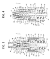
- the transverse wall 45 is adjacent to the ring of front projections 17, so as to be slightly deformed elastically in a generally plane, i.e., radial, condition (represented in Figures 3 and 4 ).
- the first internal fluid-tight member 47 of the sealing member 3 is set in fluid-tight contact against the conical surface 32a of the tip 32 of the hollow spike 2, thanks to the interaction between the outer cylindrical surfaces 40, 41 of the elastic hollow element 36 and the complementary inner cylindrical surfaces 10, 12 of the hollow body 1, whilst the second fluid-tight member 48 is set in fluid-tight contact against the area of smaller diameter of the conical part 29, thanks to the interaction between the outer cylindrical surface 44 of the elastic hollow element 36 and the complementary inner cylindrical surface 14 of the hollow body 1.
- the elastic hollow element 36 and the elastic head 35 of the sealing member 3 are normally kept in a condition of slight axial preloading within the tubular body 1, and the side holes 31 of the hollow spike 2 are isolated hermetically with respect to the inlet end 4 of the connector, communication of which with the outlet end 24 being thus closed.
- annular chamber 50 which communicates with the outside of the valve connector through one or more passages 51 formed in the base 20 of the hollow spike 2.
- annular chamber 50 Since the annular chamber 50 is in communication with the outside through the passages 51, the pressure inside it is evidently atmospheric pressure.
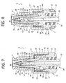
- the elastic head 35 and the elastic hollow element 36 of the sealing member 3 then slide progressively within the tubular body 1 and along the tubular post 28 of the hollow spike 2 in such a way that the first fluid-tight member 47 moves away from the conical surface 32a of the tip 32, whilst the second fluid-tight member 48 slides in a fluid-tight way along the conical part 29.
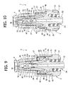
- the projections 33 of the hollow spike 2 start to interact from inside with the elastic head 35, which ( Figures 9 and 10 ) starts to assume an elastically deformed configuration, namely, radially dilated towards the outside, so as to start to open the pre-slit 38.
- the pre-slit 38 is completely opened, whilst the first fluid-tight member 47 sets itself underneath the side holes 31 of the hollow spike 2.
- the second fluid-tight member 48 has displaced slidably up to the area of larger diameter of the conical part 29 of the hollow spike 2, and the wall 45 is completely deflected and stretched within the annular chamber 50.
- the valve connector is thus in an opening condition, with the inlet end 4 (and hence the introducer S) in communication with the outlet end 24 through the pre-slit 38, the axial-radial channels 34, the side holes 31, the tubular post 28, and the shank 22.
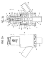
- Figures 20 to 26 illustrate a variant of the valve connector according to the invention.
- the tubular body 1 of the valve connector is provided with a tubular side wye connector 55.
- Said side connector 55 is formed integrally with the terminal cylindrical portion 6 of the tubular body 1, substantially at the height of the base 20 of the tubular spike 2.
- the base 20 is formed with a circumferential groove 56 closed on the outside in a fluid-tight way by the wall of said cylindrical terminal portion 6, which in this variant has an axial extension slightly greater than that of the preceding embodiment.
- the groove 56 thus defines an annular chamber, which on the one hand communicates with the side connector 55 through a hole 57, and on the other is connected with the cavity of the spike 2 and with the shank 22, i.e., with the outlet end 24 of the connector, through one or more radial passages 58.
- valve connector with the wye connector 55 Operation of the valve connector with the wye connector 55 is altogether identical to what was described previously with reference to Figures 3 to 12 .
- valve connector according to the invention presents, as compared to similar known valve connectors, a series of important advantages: an improved degree of reliability in terms of prompt return of the sealing member into the closed condition even following upon repeated opening; appreciably reduced overall axial dimensions; fabrication with a minimal number of parts, which can be produced in a relatively simple and inexpensive way; capacity of ensuring the substantial absence of overpressures or negative pressure inside the valve connector during the steps of transition between the condition of opening and that of closing.
Landscapes
- Health & Medical Sciences (AREA)
- Heart & Thoracic Surgery (AREA)
- Pulmonology (AREA)
- Engineering & Computer Science (AREA)
- Anesthesiology (AREA)
- Biomedical Technology (AREA)
- Hematology (AREA)
- Life Sciences & Earth Sciences (AREA)
- Animal Behavior & Ethology (AREA)
- General Health & Medical Sciences (AREA)
- Public Health (AREA)
- Veterinary Medicine (AREA)
- Infusion, Injection, And Reservoir Apparatuses (AREA)
- Quick-Acting Or Multi-Walled Pipe Joints (AREA)
Claims (19)
- Ventilverbinder für medizinische Leitungen zur Infusion mit Hilfe eines Fluidinserters (S), enthaltend:- einen röhrenförmigen Körper, der einen Hohlraum (19), ein Einlassende (4), das für den Eingriff eines Inserters (S) vorgesehen ist, und ein Auslassende (24) hat;- einen hohlen Dorn (2), der axial innerhalb des Hohlraums des röhrenförmigen Körpers (1) angeordnet ist und eine geschlossene Spitze (32) hat, die dem Einlassende (4) des röhrenförmigen Körpers (1) zugewandt ist und in einem axialen Abstand zu diesem angeordnet ist, wobei der hohle Dorn (2) mit dem Auslassende (24) in Verbindung steht und über wenigstens ein Seitenloch (31) verfügt, das in einem Abstand von der geschlossenen Spitze (32) für eine Verbindung mit dem Hohlraum (19) des röhrenförmigen Körpers (1) angeordnet ist; und- ein Dichtungselement (3), das enthält:ein elastisches hohles Element (36), das mit dem Kopf (35) verbunden ist und zwischen dem röhrenförmigen Körper (1) und dem hohlen Dorn (2) angeordnet ist und über eine Dichtungseinrichtung (47, 48) verfügt, die mit dem hohlen Dorn (2) in Kontakt steht, um das wenigstens eine Seitenloch (31) von dem Hohlraum des röhrenförmigen Körpers (1) zu isolieren, wenn sich der Kopf (35) in dem zuvor erwähnten unverformten, geschlossenen Zustand befindet, wobei das elastische hohle Element (36) eine elastische Schubeinrichtung (36, 45) enthält, die dazu neigt, den Kopf (35) in dem Schließzustand zu halten,- einen elastischen Kopf (35), der eine Vorschlitzung (38) hat und normalerweise in einem geschlossenen Zustand innerhalb des Einlassendes (4) des röhrenförmigen Körpers (1) angeordnet ist, bei dem die Vorschlitzung (38) geschlossen ist, wobei der elastische Kopf (35) axial gegen die geschlossene Spitze (32) des hohlen Dorns (2) infolge des Einfügens des Inserters (S) in das Einlassende (4) verschoben werden kann, um mit der geschlossenen Spitze (32) zu interagieren, und dabei einen elastisch verformten Öffnungszustand der Vorschlitzung (38) annimmt;
wobei der Ventilverbinder dadurch gekennzeichnet ist, dass die elastische Schubeinrichtung einen Basisteil (37) des Dichtungselementes (3) enthält, der eine im wesentlichen zylindrische, axiale Wand hat, die in einem radialen Abstand zu dem hohlen Dorn (2) angeordnet ist, um mit diesem eine ringförmige Kammer (50) auszubilden, wobei der Basisteil (37) mit dem elastischen hohlen Element (36) durch eine im wesentlichen quer verlaufende ringförmige Wand (45) verbunden ist, die sich während der axialen Verschiebung des elastischen Kopfes (35) aus dem Schließzustand in den Öffnungszustand innerhalb der ringförmigen Kammer (50) biegt. - Ventilverbinder nach Anspruch 1, dadurch gekennzeichnet, dass sich die im wesentlichen quer verlaufende Wand (45) unter Ausführung einer Verformung infolge einer Zugspannung biegt.
- Ventilverbinder nach Anspruch 1, dadurch gekennzeichnet, dass die Dichtungseinrichtung des elastischen hohlen Elementes (36) des Dichtungselementes (3) einen ersten inneren ringförmigen Vorsprung (47) und einen zweiten inneren ringförmigen Vorsprung (48) enthält, die in axialen Abständen voneinander entfernt angebracht sind und auf gegenüberliegenden Seiten im Bezug auf das wenigstens eine Seitenloch (31) des hohlen Dorns (2) in dem zuvor erwähnten Schließzustand des elastischen Kopfes (35) angeordnet sind.
- Ventilverbinder nach Anspruch 3, dadurch gekennzeichnet, dass der erste ringförmige Vorsprung (47) im Schließzustand des elastischen Kopfes (35) in fluiddichtem Kontakt mit einem ringförmigen Vorsprung innerhalb einer konischen Oberfläche (32a) gehalten ist, die in der Nähe der geschlossenen Spitze (32) des hohlen Dorns (2) ausgebildet ist.
- Ventilverbinder nach Anspruch 3, dadurch gekennzeichnet, dass der zweite ringförmige Vorsprung (48) in einem fluiddichten Gleitkontakt mit einem Abschnitt innerhalb einer konischen Oberfläche (29) des hohlen Dorns (2) angeordnet ist, die intern die ringförmige Kammer (50) begrenzt und sich zum Auslassende (24) des Verbinders weitet.
- Ventilverbinder nach Anspruch 1, dadurch gekennzeichnet, dass die ringförmige Kammer (50) mit der Außenseite des Verbinders in Kontakt steht.
- Ventilverbinder nach Anspruch 5, dadurch gekennzeichnet, dass der Basisteil (37) der elastischen Schubeinrichtung des Dichtungselementes (3) zwischen dem röhrenförmigen Körper (1) und einem Basisteil (20) des hohlen Dorns (2) axial blockiert ist.
- Ventilverbinder nach Anspruch 1, dadurch gekennzeichnet, dass der elastische Kopf (35) des Dichtungselementes (3) im Schließzustand im wesentlichen ohne Eingriff innerhalb des Einlassendes (4) des röhrenförmigen Körpers (1) angeordnet ist.
- Ventilverbinder nach Anspruch 8, dadurch gekennzeichnet, dass das Einlassende (4) des röhrenförmigen Körpers (1) eine Innenwand (7) hat, die mit axialen Kanälen (8) ausgebildet ist.
- Ventilverbinder nach Anspruch 1, dadurch gekennzeichnet, dass das elastische hohle Element (36) des Dichtungselementes (3) eine Außenwand mit axialen Abschnitten hat, die eine zylindrische Oberfläche (40, 41, 44) haben und miteinander durch Abschnitte verbunden sind, die die Form eines Kegelstumpfes haben, und dadurch, dass der röhrenförmige Körper (1) in dem Bereich entsprechend dem elastischen hohlen Element (36) eine Innenoberfläche komplementärer Form hat.
- Ventilverbinder nach Anspruch 1, dadurch gekennzeichnet, dass die im wesentlichen quer verlaufende Wand (45) des Dichtungselementes (3) eine Dicke aufweist, die im wesentlichen geringer ist als jene des elastischen hohlen Elementes (36).
- Ventilverbinder nach Anspruch 1, dadurch gekennzeichnet, dass der Basisteil (37) des Dichtungselementes (3) in einem geweiteten zylindrischen Abschnitt (6) des ringförmigen Körpers (1) aufgenommen ist, der mit einem Ring axialer Vorsprünge (18) ausgebildet ist, die radial zum Basisteil (37) hervorragen.
- Ventilverbinder nach Anspruch 12, dadurch gekennzeichnet, dass der geweitete zylindrische Abschnitt (6) des röhrenförmigen Körpers (1) mit einem Ring axialer Vorsprünge (17) ausgebildet ist, die auf der Vorderseite zu der im wesentlichen quer verlaufenden Wand (45) des Dichtungselementes (3) verlaufen.
- Ventilverbinder nach Anspruch 1, dadurch gekennzeichnet, dass die geschlossene Spitze (32) des hohlen Dorns (2) derart geformt ist, dass sie bewirkt, dass der elastische Kopf (35) des Dichtungselementes (3) den Öffnungszustand ohne Querung der Vorschlitzung (38) annimmt.
- Ventilverbinder nach Anspruch 14, dadurch gekennzeichnet, dass die geschlossene Spitze (32) des hohlen Dorns (2) eine Vielzahl axialer Vorsprünge (33) aufweist, die in Winkelabständen voneinander entfernt angeordnet sind und Strömungskanäle (34) begrenzen, die dem Einlassende (4) des röhrenförmigen Körpers (1) zugewandt sind.
- Ventilverbinder nach Anspruch 1, dadurch gekennzeichnet, dass das Auslassende (24) aus einem Luer-Lock-Steckerverbindungselement (22, 23) besteht, das integral mit dem hohlen Dorn (2) ausgebildet ist.
- Ventilverbinder nach wenigstens einem der vorhergehenden Ansprüche, dadurch gekennzeichnet, dass der röhrenförmige Körper (1) mit einem seitlichen röhrenförmigen Y-Verbinder (55) ausgebildet ist.
- Ventilverbinder nach Anspruch 17, dadurch gekennzeichnet, dass der röhrenförmige Y-Verbinder (55) mit dem Auslassende (24) des Verbinders durch eine ringförmige Kammer (56) verbunden ist, die mit dem Inneren des hohlen Dorns (2) stromabwärts des wenigstens einen Seitenloches (31) in Verbindung steht.
- Ventilverbinder nach Anspruch 18, dadurch gekennzeichnet, das die ringförmige Kammer durch eine Umfangsrille (56) eines vergrößerten Abschnittes (20) des hohlen Dorns (2) ausgebildet ist, die auf der Außenseite durch den röhrenförmigen Körper (1) geschlossen ist und mit dem Auslassende des Verbinders (24) durch wenigstens einen radialen Leitungsweg des vergrößerten Abschnittes (20) verbunden ist.
Applications Claiming Priority (1)
| Application Number | Priority Date | Filing Date | Title |
|---|---|---|---|
| IT000206A ITTO20060206A1 (it) | 2006-03-17 | 2006-03-17 | Connettore valvolare per linee medicali |
Publications (2)
| Publication Number | Publication Date |
|---|---|
| EP1834665A1 EP1834665A1 (de) | 2007-09-19 |
| EP1834665B1 true EP1834665B1 (de) | 2010-02-17 |
Family
ID=38518483
Family Applications (1)
| Application Number | Title | Priority Date | Filing Date |
|---|---|---|---|
| EP07104236A Active EP1834665B1 (de) | 2006-03-17 | 2007-03-15 | Ventilverbinder für medizinische Leitungen |
Country Status (12)
| Country | Link |
|---|---|
| US (1) | US8048038B2 (de) |
| EP (1) | EP1834665B1 (de) |
| CN (1) | CN101152594B (de) |
| AT (1) | ATE457772T1 (de) |
| AU (1) | AU2007201164B8 (de) |
| CA (1) | CA2581547C (de) |
| DE (1) | DE602007004754D1 (de) |
| ES (1) | ES2341040T3 (de) |
| IT (1) | ITTO20060206A1 (de) |
| PT (1) | PT1834665E (de) |
| SG (1) | SG136057A1 (de) |
| ZA (1) | ZA200702197B (de) |
Cited By (1)
| Publication number | Priority date | Publication date | Assignee | Title |
|---|---|---|---|---|
| US9586037B2 (en) | 2009-11-26 | 2017-03-07 | Industrie Borla S.P.A. | Valved male luer connector |
Families Citing this family (57)
| Publication number | Priority date | Publication date | Assignee | Title |
|---|---|---|---|---|
| US6695817B1 (en) | 2000-07-11 | 2004-02-24 | Icu Medical, Inc. | Medical valve with positive flow characteristics |
| US7837658B2 (en) | 2001-11-13 | 2010-11-23 | Nypro Inc. | Anti-drawback medical valve |
| US7753892B2 (en) | 2001-11-13 | 2010-07-13 | Nypro Inc. | Anti-drawback medical valve |
| US7914502B2 (en) | 2003-07-31 | 2011-03-29 | Nypro Inc. | Anti-drawback medical valve |
| ES2380911T3 (es) | 2004-11-05 | 2012-05-21 | Icu Medical, Inc. | Conector médico que tiene características de alto flujo |
| US8002755B2 (en) | 2006-04-11 | 2011-08-23 | Nypro Inc. | Anti-drawback medical valve and method |
| CA2660838A1 (en) | 2006-08-11 | 2008-02-21 | Nypro Inc. | Medical valve with expandable member |
| CA2644187A1 (en) | 2007-12-05 | 2009-06-05 | Tyco Healthcare Group Lp | Device for reducing microbial contamination |
| ITTO20080059A1 (it) * | 2008-01-29 | 2009-07-30 | Industrie Borla Spa | Connettore valvolare per linee medicali |
| EP2259839B1 (de) * | 2008-03-04 | 2015-12-23 | Infusion Innovations, Inc. | Vorrichtungen, anordnungen und verfahren zur kontrolle des flüssigkeitsflusses |
| ITTO20080381A1 (it) | 2008-05-21 | 2009-11-22 | Industrie Borla Spa | Connettore valvolare per linee medicali |
| IT1392847B1 (it) | 2009-01-14 | 2012-03-23 | Borla Ind | Connettore valvolare per linee medicali |
| US8469928B2 (en) * | 2009-02-11 | 2013-06-25 | Becton, Dickinson And Company | Systems and methods for providing a flushable catheter assembly |
| EP2411715B1 (de) * | 2009-03-22 | 2019-01-30 | Elcam Medical Agricultural Cooperative Association Ltd. | Verschlossener luer-stecker |
| US8454579B2 (en) | 2009-03-25 | 2013-06-04 | Icu Medical, Inc. | Medical connector with automatic valves and volume regulator |
| PT2445572T (pt) | 2009-06-22 | 2018-11-02 | Np Medical Inc | Válvula médica com vedação de contrapressão melhorada |
| TR200906911A1 (tr) * | 2009-09-08 | 2010-12-21 | Asset Medi̇kal Tasarim Sanayi̇ Ve Ti̇caret Anoni̇m Şi̇rketi̇ | Silinebilir iğnesiz valf. |
| USD644731S1 (en) | 2010-03-23 | 2011-09-06 | Icu Medical, Inc. | Medical connector |
| US8298196B1 (en) * | 2010-03-24 | 2012-10-30 | Mansour George M | Needleless access connector and method of use |
| US8758306B2 (en) | 2010-05-17 | 2014-06-24 | Icu Medical, Inc. | Medical connectors and methods of use |
| US9138572B2 (en) | 2010-06-24 | 2015-09-22 | Np Medical Inc. | Medical valve with fluid volume alteration |
| JP5908502B2 (ja) * | 2011-02-15 | 2016-04-26 | シーダブリューエス−ボコ サプライ アクチェンゲゼルシャフト | 液体容器用のバルブ |
| EP2554214A1 (de) * | 2011-08-04 | 2013-02-06 | B. Braun Melsungen AG | Nadelfreier Stecker mit einer faltbaren stabilen Membran und zugehöriges Verfahren |
| US8777931B2 (en) | 2011-08-19 | 2014-07-15 | Alcon Research, Ltd. | Retractable luer lock fittings |
| ITTO20120056A1 (it) * | 2012-01-24 | 2013-07-25 | Borla Ind | Connettore per linee medicali di infusione, trasfusione e simili |
| JP2014117461A (ja) * | 2012-12-17 | 2014-06-30 | Fukai Kogyo Kk | 混注管 |
| US9308362B2 (en) | 2013-03-12 | 2016-04-12 | Carefusion 303, Inc. | Male luer with fluid path and vent path seals |
| US9144672B2 (en) * | 2013-03-13 | 2015-09-29 | Carefusion 303, Inc. | Needleless connector with compressible valve |
| US9089682B2 (en) | 2013-03-14 | 2015-07-28 | Carefusion 303, Inc. | Needleless connector with support member |
| ITTO20130433A1 (it) * | 2013-05-29 | 2014-11-30 | Borla Ind | Connettore per linee medicali |
| ITMO20130264A1 (it) * | 2013-09-25 | 2015-03-26 | Giuseppe Maffei | Connettore senza ago |
| AU2014364218B2 (en) | 2013-12-11 | 2019-06-06 | Icu Medical, Inc. | Check valve |
| PT3099374T (pt) | 2014-01-31 | 2018-04-09 | Borla Ind | Conector com válvula para linhas médicas |
| DE102014214076A1 (de) | 2014-07-18 | 2016-01-21 | Hamilton Bonaduz Ag | Fluidleitungsanordnung, umfassend eine Mehrzahl von Fluidleitungselementen, Ventilleitungsanordnung, umfassend eine Fluidleitungsanordnung und eine Schaltanordnung, und Handhabungsanordnung mit einer Ventilleitungsanordnung |
| ES2976306T3 (es) * | 2014-11-12 | 2024-07-29 | Fresenius Kabi Deutschland Gmbh | Puerto de inyección intravenosa de desplazamiento neutro, intermitente, sin aguja |
| USD793551S1 (en) | 2014-12-03 | 2017-08-01 | Icu Medical, Inc. | Fluid manifold |
| USD786427S1 (en) | 2014-12-03 | 2017-05-09 | Icu Medical, Inc. | Fluid manifold |
| TWI584837B (zh) * | 2015-02-09 | 2017-06-01 | 怡安醫療器材股份有限公司 | 免針連接頭模組 |
| AU367143S (en) * | 2015-08-05 | 2016-02-15 | Borla Ind | Valved connector for medical lines |
| ITUB20152902A1 (it) | 2015-08-05 | 2017-02-05 | Borla Ind | Connettore valvolare per linee medicali |
| EP3011994B1 (de) * | 2015-08-10 | 2018-10-10 | Cair L. G. L. | Weiblicher luer-lock |
| JP6962923B2 (ja) * | 2016-09-26 | 2021-11-05 | テルモ株式会社 | オスコネクタ、医療器具及び接続方法 |
| CN106581789B (zh) * | 2016-12-12 | 2023-05-26 | 武汉维斯第医用科技股份有限公司 | 用于负压封闭引流系统的外部多管路转换器 |
| EP3565629B1 (de) * | 2017-01-09 | 2025-12-17 | Fresenius Kabi Deutschland GmbH | Verbindungsanordnung zur verbindung medizinischer leitungen miteinander |
| KR102729125B1 (ko) * | 2017-01-20 | 2024-11-13 | 삼성전자주식회사 | 케이블 방수 장치 |
| JP6924368B2 (ja) * | 2017-05-26 | 2021-08-25 | 株式会社ジェイ・エム・エス | オスコネクタ |
| DE102017210795A1 (de) * | 2017-06-27 | 2018-12-27 | B. Braun Melsungen Ag | Medizinische Fluidverbindungsvorrichtung |
| US11224555B2 (en) | 2018-04-23 | 2022-01-18 | Hospira, Inc. | Access and vapor containment system for a drug vial and method of making and using same |
| US20200316359A1 (en) * | 2019-04-04 | 2020-10-08 | Becton, Dickinson And Company | Multi-use blood control catheter assembly |
| JP7389311B2 (ja) * | 2019-06-27 | 2023-11-30 | 株式会社トップ | メスコネクタ |
| IL282356A (en) * | 2021-04-14 | 2022-11-01 | Equashield Medical Ltd | Devices for use in drug delivery systems |
| CN113607192B (zh) * | 2021-09-30 | 2021-12-14 | 武汉长盈通光电技术股份有限公司 | 间接连接式光纤陀螺组件测试装置 |
| US12465743B2 (en) * | 2022-11-08 | 2025-11-11 | Carefusion 303, Inc. | Fluid connector assembly with neutral fluid displacement that limits connector damage |
| IT202300006996A1 (it) | 2023-04-12 | 2024-10-12 | Borla Ind | Connettore valvolare per linee medicali |
| CN116570831B (zh) * | 2023-06-30 | 2024-01-05 | 江苏康进医疗器材有限公司 | 一种导管快速接头 |
| US12357808B1 (en) * | 2023-12-27 | 2025-07-15 | Asset Medical, Inc. | Connector assembly for communication of medical liquids |
| US12539408B1 (en) | 2025-01-13 | 2026-02-03 | Asset Medical, Inc. | Neutral displacement medical connector |
Family Cites Families (19)
| Publication number | Priority date | Publication date | Assignee | Title |
|---|---|---|---|---|
| DE69233329T2 (de) | 1991-12-18 | 2004-08-05 | Icu Medical, Inc., Irvine | Verfahren zum Flüssigkeitstransfer |
| US5242342A (en) | 1992-07-07 | 1993-09-07 | Bi-Robic Conditioning Systems, Inc. | Aerobic and isometric exercise apparatus |
| US5699821A (en) * | 1993-10-13 | 1997-12-23 | Paradis; Joseph R. | Control of fluid flow |
| US5439451A (en) * | 1994-03-22 | 1995-08-08 | B. Braun Medical, Inc. | Capless medical backcheck valve |
| US5820601A (en) * | 1994-06-20 | 1998-10-13 | Critical Device Corporation | Needleless injection site |
| US5514116A (en) * | 1994-10-24 | 1996-05-07 | Vlv Associates | Connector |
| NZ286445A (en) * | 1995-05-16 | 1997-12-19 | Ivac Corp | Needleless luer connector: deformable piston occludes bore |
| US5700248A (en) | 1995-12-15 | 1997-12-23 | Icu Medical, Inc. | Medical valve with tire seal |
| US6079432A (en) * | 1996-07-02 | 2000-06-27 | Paradis; Joseph R. | Control of fluid flow by oval shaped valve member containing a cam interface |
| DK0952868T3 (da) * | 1996-11-18 | 2004-07-19 | Nypro Inc | Aftörbar ventil med Luer-konus |
| US6050978A (en) * | 1997-05-09 | 2000-04-18 | Becton Dickinson And Company | Needleless valve connector |
| US6706022B1 (en) | 1999-07-27 | 2004-03-16 | Alaris Medical Systems, Inc. | Needleless medical connector with expandable valve mechanism |
| AU2002220268A1 (en) * | 2000-10-23 | 2002-05-06 | Nypro Inc. | Anti-drawback medical valve |
| EP1427472A2 (de) * | 2001-08-22 | 2004-06-16 | Nypro Inc. | Medizinisches ventil mit expandierbarem glied |
| JP4339682B2 (ja) * | 2001-08-23 | 2009-10-07 | オキュペイショナル・アンド・メディカル・イノベイションズ・リミテッド | 逆流防止バルブ |
| US6802490B2 (en) * | 2001-11-29 | 2004-10-12 | Alaris Medical Systems, Inc. | Needle free medical connector with expanded valve mechanism and method of fluid flow control |
| US7914502B2 (en) | 2003-07-31 | 2011-03-29 | Nypro Inc. | Anti-drawback medical valve |
| ITTO20040524A1 (it) * | 2004-07-27 | 2004-10-27 | Borla Ind | Connettore valvolareper linee medicali di infusione |
| US7296782B2 (en) * | 2004-10-01 | 2007-11-20 | Halkey-Roberts Corporation | Dome check valve |
-
2006
- 2006-03-17 IT IT000206A patent/ITTO20060206A1/it unknown
-
2007
- 2007-03-08 SG SG200701720-5A patent/SG136057A1/en unknown
- 2007-03-12 CA CA2581547A patent/CA2581547C/en active Active
- 2007-03-15 ZA ZA2007/02197A patent/ZA200702197B/en unknown
- 2007-03-15 EP EP07104236A patent/EP1834665B1/de active Active
- 2007-03-15 PT PT07104236T patent/PT1834665E/pt unknown
- 2007-03-15 DE DE602007004754T patent/DE602007004754D1/de active Active
- 2007-03-15 AT AT07104236T patent/ATE457772T1/de not_active IP Right Cessation
- 2007-03-15 ES ES07104236T patent/ES2341040T3/es active Active
- 2007-03-16 US US11/687,188 patent/US8048038B2/en active Active
- 2007-03-16 CN CN2007101676346A patent/CN101152594B/zh active Active
- 2007-03-16 AU AU2007201164A patent/AU2007201164B8/en active Active
Cited By (1)
| Publication number | Priority date | Publication date | Assignee | Title |
|---|---|---|---|---|
| US9586037B2 (en) | 2009-11-26 | 2017-03-07 | Industrie Borla S.P.A. | Valved male luer connector |
Also Published As
| Publication number | Publication date |
|---|---|
| CA2581547A1 (en) | 2007-09-17 |
| SG136057A1 (en) | 2007-10-29 |
| ITTO20060206A1 (it) | 2007-09-18 |
| ZA200702197B (en) | 2008-08-27 |
| US8048038B2 (en) | 2011-11-01 |
| AU2007201164B8 (en) | 2008-11-27 |
| CN101152594A (zh) | 2008-04-02 |
| CA2581547C (en) | 2010-07-27 |
| PT1834665E (pt) | 2010-04-26 |
| DE602007004754D1 (de) | 2010-04-01 |
| ATE457772T1 (de) | 2010-03-15 |
| EP1834665A1 (de) | 2007-09-19 |
| US20070218757A1 (en) | 2007-09-20 |
| AU2007201164A1 (en) | 2007-10-04 |
| ES2341040T3 (es) | 2010-06-14 |
| AU2007201164B2 (en) | 2008-08-28 |
| CN101152594B (zh) | 2010-10-27 |
Similar Documents
| Publication | Publication Date | Title |
|---|---|---|
| EP1834665B1 (de) | Ventilverbinder für medizinische Leitungen | |
| CA2665722C (en) | Valve connector for medical lines | |
| EP1773445B1 (de) | Ventilverbinder für medizinische infusionsleitungen | |
| EP2331185B1 (de) | Luer-aktivierter medizinischer steckverbinder mit geringem priming-volumen | |
| US20240342370A1 (en) | Valve connector for medical lines | |
| JP4526549B2 (ja) | 医療ライン用バルブコネクタ | |
| EP3331599B1 (de) | Ventilverbinder für medizinische leitungen | |
| US20250186689A1 (en) | Needle-free connectors | |
| NZ739087B2 (en) | Valve connector for medical lines |
Legal Events
| Date | Code | Title | Description |
|---|---|---|---|
| PUAI | Public reference made under article 153(3) epc to a published international application that has entered the european phase |
Free format text: ORIGINAL CODE: 0009012 |
|
| AK | Designated contracting states |
Kind code of ref document: A1 Designated state(s): AT BE BG CH CY CZ DE DK EE ES FI FR GB GR HU IE IS IT LI LT LU LV MC MT NL PL PT RO SE SI SK TR |
|
| AX | Request for extension of the european patent |
Extension state: AL BA HR MK YU |
|
| 17P | Request for examination filed |
Effective date: 20071227 |
|
| AKX | Designation fees paid |
Designated state(s): AT BE BG CH CY CZ DE DK EE ES FI FR GB GR HU IE IS IT LI LT LU LV MC MT NL PL PT RO SE SI SK TR |
|
| GRAP | Despatch of communication of intention to grant a patent |
Free format text: ORIGINAL CODE: EPIDOSNIGR1 |
|
| GRAS | Grant fee paid |
Free format text: ORIGINAL CODE: EPIDOSNIGR3 |
|
| GRAA | (expected) grant |
Free format text: ORIGINAL CODE: 0009210 |
|
| AK | Designated contracting states |
Kind code of ref document: B1 Designated state(s): AT BE BG CH CY CZ DE DK EE ES FI FR GB GR HU IE IS IT LI LT LU LV MC MT NL PL PT RO SE SI SK TR |
|
| REG | Reference to a national code |
Ref country code: GB Ref legal event code: FG4D |
|
| REG | Reference to a national code |
Ref country code: CH Ref legal event code: EP |
|
| REG | Reference to a national code |
Ref country code: IE Ref legal event code: FG4D |
|
| REF | Corresponds to: |
Ref document number: 602007004754 Country of ref document: DE Date of ref document: 20100401 Kind code of ref document: P |
|
| REG | Reference to a national code |
Ref country code: PT Ref legal event code: SC4A Free format text: AVAILABILITY OF NATIONAL TRANSLATION Effective date: 20100420 |
|
| REG | Reference to a national code |
Ref country code: NL Ref legal event code: T3 |
|
| REG | Reference to a national code |
Ref country code: SE Ref legal event code: TRGR |
|
| REG | Reference to a national code |
Ref country code: ES Ref legal event code: FG2A Ref document number: 2341040 Country of ref document: ES Kind code of ref document: T3 |
|
| LTIE | Lt: invalidation of european patent or patent extension |
Effective date: 20100217 |
|
| PG25 | Lapsed in a contracting state [announced via postgrant information from national office to epo] |
Ref country code: IS Free format text: LAPSE BECAUSE OF FAILURE TO SUBMIT A TRANSLATION OF THE DESCRIPTION OR TO PAY THE FEE WITHIN THE PRESCRIBED TIME-LIMIT Effective date: 20100617 Ref country code: LT Free format text: LAPSE BECAUSE OF FAILURE TO SUBMIT A TRANSLATION OF THE DESCRIPTION OR TO PAY THE FEE WITHIN THE PRESCRIBED TIME-LIMIT Effective date: 20100217 |
|
| PG25 | Lapsed in a contracting state [announced via postgrant information from national office to epo] |
Ref country code: SI Free format text: LAPSE BECAUSE OF FAILURE TO SUBMIT A TRANSLATION OF THE DESCRIPTION OR TO PAY THE FEE WITHIN THE PRESCRIBED TIME-LIMIT Effective date: 20100217 Ref country code: PL Free format text: LAPSE BECAUSE OF FAILURE TO SUBMIT A TRANSLATION OF THE DESCRIPTION OR TO PAY THE FEE WITHIN THE PRESCRIBED TIME-LIMIT Effective date: 20100217 Ref country code: LV Free format text: LAPSE BECAUSE OF FAILURE TO SUBMIT A TRANSLATION OF THE DESCRIPTION OR TO PAY THE FEE WITHIN THE PRESCRIBED TIME-LIMIT Effective date: 20100217 Ref country code: FI Free format text: LAPSE BECAUSE OF FAILURE TO SUBMIT A TRANSLATION OF THE DESCRIPTION OR TO PAY THE FEE WITHIN THE PRESCRIBED TIME-LIMIT Effective date: 20100217 Ref country code: AT Free format text: LAPSE BECAUSE OF FAILURE TO SUBMIT A TRANSLATION OF THE DESCRIPTION OR TO PAY THE FEE WITHIN THE PRESCRIBED TIME-LIMIT Effective date: 20100217 |
|
| PG25 | Lapsed in a contracting state [announced via postgrant information from national office to epo] |
Ref country code: RO Free format text: LAPSE BECAUSE OF FAILURE TO SUBMIT A TRANSLATION OF THE DESCRIPTION OR TO PAY THE FEE WITHIN THE PRESCRIBED TIME-LIMIT Effective date: 20100217 Ref country code: CY Free format text: LAPSE BECAUSE OF FAILURE TO SUBMIT A TRANSLATION OF THE DESCRIPTION OR TO PAY THE FEE WITHIN THE PRESCRIBED TIME-LIMIT Effective date: 20100217 Ref country code: GR Free format text: LAPSE BECAUSE OF FAILURE TO SUBMIT A TRANSLATION OF THE DESCRIPTION OR TO PAY THE FEE WITHIN THE PRESCRIBED TIME-LIMIT Effective date: 20100518 Ref country code: EE Free format text: LAPSE BECAUSE OF FAILURE TO SUBMIT A TRANSLATION OF THE DESCRIPTION OR TO PAY THE FEE WITHIN THE PRESCRIBED TIME-LIMIT Effective date: 20100217 |
|
| PG25 | Lapsed in a contracting state [announced via postgrant information from national office to epo] |
Ref country code: SK Free format text: LAPSE BECAUSE OF FAILURE TO SUBMIT A TRANSLATION OF THE DESCRIPTION OR TO PAY THE FEE WITHIN THE PRESCRIBED TIME-LIMIT Effective date: 20100217 Ref country code: BG Free format text: LAPSE BECAUSE OF FAILURE TO SUBMIT A TRANSLATION OF THE DESCRIPTION OR TO PAY THE FEE WITHIN THE PRESCRIBED TIME-LIMIT Effective date: 20100517 Ref country code: CZ Free format text: LAPSE BECAUSE OF FAILURE TO SUBMIT A TRANSLATION OF THE DESCRIPTION OR TO PAY THE FEE WITHIN THE PRESCRIBED TIME-LIMIT Effective date: 20100217 |
|
| PLBE | No opposition filed within time limit |
Free format text: ORIGINAL CODE: 0009261 |
|
| STAA | Information on the status of an ep patent application or granted ep patent |
Free format text: STATUS: NO OPPOSITION FILED WITHIN TIME LIMIT |
|
| 26N | No opposition filed |
Effective date: 20101118 |
|
| PG25 | Lapsed in a contracting state [announced via postgrant information from national office to epo] |
Ref country code: DK Free format text: LAPSE BECAUSE OF FAILURE TO SUBMIT A TRANSLATION OF THE DESCRIPTION OR TO PAY THE FEE WITHIN THE PRESCRIBED TIME-LIMIT Effective date: 20100217 |
|
| PG25 | Lapsed in a contracting state [announced via postgrant information from national office to epo] |
Ref country code: MT Free format text: LAPSE BECAUSE OF FAILURE TO SUBMIT A TRANSLATION OF THE DESCRIPTION OR TO PAY THE FEE WITHIN THE PRESCRIBED TIME-LIMIT Effective date: 20100217 |
|
| PGRI | Patent reinstated in contracting state [announced from national office to epo] |
Ref country code: IT Effective date: 20110501 |
|
| REG | Reference to a national code |
Ref country code: CH Ref legal event code: PL |
|
| PG25 | Lapsed in a contracting state [announced via postgrant information from national office to epo] |
Ref country code: LI Free format text: LAPSE BECAUSE OF NON-PAYMENT OF DUE FEES Effective date: 20110331 Ref country code: CH Free format text: LAPSE BECAUSE OF NON-PAYMENT OF DUE FEES Effective date: 20110331 |
|
| PG25 | Lapsed in a contracting state [announced via postgrant information from national office to epo] |
Ref country code: LU Free format text: LAPSE BECAUSE OF NON-PAYMENT OF DUE FEES Effective date: 20100315 Ref country code: HU Free format text: LAPSE BECAUSE OF FAILURE TO SUBMIT A TRANSLATION OF THE DESCRIPTION OR TO PAY THE FEE WITHIN THE PRESCRIBED TIME-LIMIT Effective date: 20100818 |
|
| PG25 | Lapsed in a contracting state [announced via postgrant information from national office to epo] |
Ref country code: TR Free format text: LAPSE BECAUSE OF FAILURE TO SUBMIT A TRANSLATION OF THE DESCRIPTION OR TO PAY THE FEE WITHIN THE PRESCRIBED TIME-LIMIT Effective date: 20100217 |
|
| REG | Reference to a national code |
Ref country code: FR Ref legal event code: PLFP Year of fee payment: 10 |
|
| REG | Reference to a national code |
Ref country code: FR Ref legal event code: PLFP Year of fee payment: 11 |
|
| REG | Reference to a national code |
Ref country code: FR Ref legal event code: PLFP Year of fee payment: 12 |
|
| P01 | Opt-out of the competence of the unified patent court (upc) registered |
Effective date: 20230614 |
|
| PGFP | Annual fee paid to national office [announced via postgrant information from national office to epo] |
Ref country code: PT Payment date: 20250224 Year of fee payment: 19 |
|
| PGFP | Annual fee paid to national office [announced via postgrant information from national office to epo] |
Ref country code: ES Payment date: 20250415 Year of fee payment: 19 |
|
| PGFP | Annual fee paid to national office [announced via postgrant information from national office to epo] |
Ref country code: SE Payment date: 20260323 Year of fee payment: 20 |
|
| PGFP | Annual fee paid to national office [announced via postgrant information from national office to epo] |
Ref country code: GB Payment date: 20260304 Year of fee payment: 20 |
|
| PGFP | Annual fee paid to national office [announced via postgrant information from national office to epo] |
Ref country code: MC Payment date: 20260320 Year of fee payment: 20 |
|
| PGFP | Annual fee paid to national office [announced via postgrant information from national office to epo] |
Ref country code: DE Payment date: 20260320 Year of fee payment: 20 Ref country code: IE Payment date: 20260318 Year of fee payment: 20 |
|
| PGFP | Annual fee paid to national office [announced via postgrant information from national office to epo] |
Ref country code: BE Payment date: 20260323 Year of fee payment: 20 Ref country code: IT Payment date: 20260227 Year of fee payment: 20 |
|
| PGFP | Annual fee paid to national office [announced via postgrant information from national office to epo] |
Ref country code: NL Payment date: 20260323 Year of fee payment: 20 |
|
| PGFP | Annual fee paid to national office [announced via postgrant information from national office to epo] |
Ref country code: FR Payment date: 20260323 Year of fee payment: 20 |