EP1834665B1 - A valve connector for medical lines - Google Patents
A valve connector for medical lines Download PDFInfo
- Publication number
- EP1834665B1 EP1834665B1 EP07104236A EP07104236A EP1834665B1 EP 1834665 B1 EP1834665 B1 EP 1834665B1 EP 07104236 A EP07104236 A EP 07104236A EP 07104236 A EP07104236 A EP 07104236A EP 1834665 B1 EP1834665 B1 EP 1834665B1
- Authority
- EP
- European Patent Office
- Prior art keywords
- elastic
- tubular body
- valve connector
- connector according
- sealing member
- Prior art date
- Legal status (The legal status is an assumption and is not a legal conclusion. Google has not performed a legal analysis and makes no representation as to the accuracy of the status listed.)
- Active
Links
- 238000007789 sealing Methods 0.000 claims abstract description 41
- 238000001802 infusion Methods 0.000 claims abstract description 5
- 238000006073 displacement reaction Methods 0.000 claims abstract description 3
- 238000004891 communication Methods 0.000 claims description 12
- 230000000295 complement effect Effects 0.000 claims description 6
- 238000003780 insertion Methods 0.000 claims description 5
- 230000037431 insertion Effects 0.000 claims description 5
- 239000012530 fluid Substances 0.000 claims description 3
- 230000000844 anti-bacterial effect Effects 0.000 description 2
- 230000004888 barrier function Effects 0.000 description 2
- 230000006835 compression Effects 0.000 description 2
- 238000007906 compression Methods 0.000 description 2
- 239000000645 desinfectant Substances 0.000 description 2
- 230000003993 interaction Effects 0.000 description 2
- 230000000284 resting effect Effects 0.000 description 2
- 230000007704 transition Effects 0.000 description 2
- 238000004140 cleaning Methods 0.000 description 1
- 238000010276 construction Methods 0.000 description 1
- 230000005489 elastic deformation Effects 0.000 description 1
- 239000013013 elastic material Substances 0.000 description 1
- 238000000605 extraction Methods 0.000 description 1
- 239000007788 liquid Substances 0.000 description 1
- 238000004519 manufacturing process Methods 0.000 description 1
- 239000000463 material Substances 0.000 description 1
- 239000002991 molded plastic Substances 0.000 description 1
- 230000000750 progressive effect Effects 0.000 description 1
- 229920002379 silicone rubber Polymers 0.000 description 1
- 239000004945 silicone rubber Substances 0.000 description 1
- 239000000126 substance Substances 0.000 description 1
- 230000004083 survival effect Effects 0.000 description 1
Images


Classifications
-
- A—HUMAN NECESSITIES
- A61—MEDICAL OR VETERINARY SCIENCE; HYGIENE
- A61M—DEVICES FOR INTRODUCING MEDIA INTO, OR ONTO, THE BODY; DEVICES FOR TRANSDUCING BODY MEDIA OR FOR TAKING MEDIA FROM THE BODY; DEVICES FOR PRODUCING OR ENDING SLEEP OR STUPOR
- A61M39/00—Tubes, tube connectors, tube couplings, valves, access sites or the like, specially adapted for medical use
- A61M39/22—Valves or arrangement of valves
- A61M39/26—Valves closing automatically on disconnecting the line and opening on reconnection thereof
-
- A—HUMAN NECESSITIES
- A61—MEDICAL OR VETERINARY SCIENCE; HYGIENE
- A61M—DEVICES FOR INTRODUCING MEDIA INTO, OR ONTO, THE BODY; DEVICES FOR TRANSDUCING BODY MEDIA OR FOR TAKING MEDIA FROM THE BODY; DEVICES FOR PRODUCING OR ENDING SLEEP OR STUPOR
- A61M39/00—Tubes, tube connectors, tube couplings, valves, access sites or the like, specially adapted for medical use
- A61M39/02—Access sites
- A61M39/04—Access sites having pierceable self-sealing members
- A61M39/045—Access sites having pierceable self-sealing members pre-slit to be pierced by blunt instrument
-
- A—HUMAN NECESSITIES
- A61—MEDICAL OR VETERINARY SCIENCE; HYGIENE
- A61M—DEVICES FOR INTRODUCING MEDIA INTO, OR ONTO, THE BODY; DEVICES FOR TRANSDUCING BODY MEDIA OR FOR TAKING MEDIA FROM THE BODY; DEVICES FOR PRODUCING OR ENDING SLEEP OR STUPOR
- A61M39/00—Tubes, tube connectors, tube couplings, valves, access sites or the like, specially adapted for medical use
- A61M39/10—Tube connectors; Tube couplings
-
- A—HUMAN NECESSITIES
- A61—MEDICAL OR VETERINARY SCIENCE; HYGIENE
- A61M—DEVICES FOR INTRODUCING MEDIA INTO, OR ONTO, THE BODY; DEVICES FOR TRANSDUCING BODY MEDIA OR FOR TAKING MEDIA FROM THE BODY; DEVICES FOR PRODUCING OR ENDING SLEEP OR STUPOR
- A61M39/00—Tubes, tube connectors, tube couplings, valves, access sites or the like, specially adapted for medical use
- A61M2039/0036—Tubes, tube connectors, tube couplings, valves, access sites or the like, specially adapted for medical use characterised by a septum having particular features, e.g. having venting channels or being made from antimicrobial or self-lubricating elastomer
-
- A—HUMAN NECESSITIES
- A61—MEDICAL OR VETERINARY SCIENCE; HYGIENE
- A61M—DEVICES FOR INTRODUCING MEDIA INTO, OR ONTO, THE BODY; DEVICES FOR TRANSDUCING BODY MEDIA OR FOR TAKING MEDIA FROM THE BODY; DEVICES FOR PRODUCING OR ENDING SLEEP OR STUPOR
- A61M39/00—Tubes, tube connectors, tube couplings, valves, access sites or the like, specially adapted for medical use
- A61M39/10—Tube connectors; Tube couplings
- A61M2039/1033—Swivel nut connectors, e.g. threaded connectors, bayonet-connectors
-
- A—HUMAN NECESSITIES
- A61—MEDICAL OR VETERINARY SCIENCE; HYGIENE
- A61M—DEVICES FOR INTRODUCING MEDIA INTO, OR ONTO, THE BODY; DEVICES FOR TRANSDUCING BODY MEDIA OR FOR TAKING MEDIA FROM THE BODY; DEVICES FOR PRODUCING OR ENDING SLEEP OR STUPOR
- A61M39/00—Tubes, tube connectors, tube couplings, valves, access sites or the like, specially adapted for medical use
- A61M39/22—Valves or arrangement of valves
- A61M39/26—Valves closing automatically on disconnecting the line and opening on reconnection thereof
- A61M2039/263—Valves closing automatically on disconnecting the line and opening on reconnection thereof where the fluid space within the valve is decreasing upon disconnection
-
- A—HUMAN NECESSITIES
- A61—MEDICAL OR VETERINARY SCIENCE; HYGIENE
- A61M—DEVICES FOR INTRODUCING MEDIA INTO, OR ONTO, THE BODY; DEVICES FOR TRANSDUCING BODY MEDIA OR FOR TAKING MEDIA FROM THE BODY; DEVICES FOR PRODUCING OR ENDING SLEEP OR STUPOR
- A61M39/00—Tubes, tube connectors, tube couplings, valves, access sites or the like, specially adapted for medical use
- A61M39/22—Valves or arrangement of valves
- A61M39/26—Valves closing automatically on disconnecting the line and opening on reconnection thereof
- A61M2039/267—Valves closing automatically on disconnecting the line and opening on reconnection thereof having a sealing sleeve around a tubular or solid stem portion of the connector
Definitions
- the present invention relates to valve connectors for medical lines, for example lines for infusion by means of an introducer for introducing a fluid infusion substance, typically a luer connector or luer-lock connector, for example of a needleless syringe.
- a fluid infusion substance typically a luer connector or luer-lock connector, for example of a needleless syringe.
- Valve connectors of this type are known, for example, from the documents Nos. US-5242342 , US-5676346 , US-6706022 , US-5700248 and US-6682509 .
- a valve connector according to the preamble of Claim 1, in which a tubular body is provided having a cavity, an inlet end provided for engagement of an introducer of liquid, and an outlet end.
- a hollow spike is set axially within the cavity of the tubular body and has a closed tip facing the inlet end of the tubular body and set at an axial distance from this.
- the hollow spike is in communication with the outlet end of the tubular body and has at least one side hole set at a distance from its closed tip for communication with the cavity of the tubular body.
- the connector moreover includes an elastic sealing member, which comprises an elastic head having a pre-slit and normally set in a condition of closing (or deactivated condition) within the inlet end of the tubular body, in which the pre-slit is closed.
- the elastic head is displaceable axially against the closed tip of the hollow spike as a result of insertion of the introducer into the inlet end of the tubular body in order to interact with said tip, assuming an elastically deformed configuration of opening (activated condition), in which the pre-slit opens.
- the sealing member of the valve connector moreover includes an elastic hollow element joined to the head, set between the tubular body and the hollow spike and having sealing means in contact with said hollow spike for isolating the aforesaid at least one side hole from the cavity of the tubular body when the head is set in the undeformed condition of closing.
- the elastic hollow element includes an elastic thrust means, which tends to maintain the head of the sealing member in the aforesaid condition of closing.
- Valve connectors of the above type must meet a series of fundamental requisites, since their use is frequently critical for survival of patients that make use thereof.
- closing of the inlet end of the tubular body performed by the head of the sealing member must be substantially fluid-tight so as to ensure a total anti-bacterial barrier, even following upon repeated opening and re-closing of the valve connector.
- these connectors In the third place, these connectors must be able to support effectively possible overpressures that may be generated inside them in use, and in the condition of closing (or deactivated condition) guarantee an effective fluid-tightness at positive and negative pressures.
- valve connectors must be easily cleanable and disinfectable (“swabbable”) at the inlet end, typically using a swab soaked in disinfectant.
- valve connectors known from the aforementioned documents Nos. US-5700248 and US-6682509
- opening of the communication between the inlet end of the tubular body and the outlet end, through the side hole or holes of the hollow spike at the moment of engagement of the introducer, is performed following upon traversal of the pre-slit of the elastic head by the tip of the hollow spike.
- the closed tip of the hollow spike is, instead, shaped so as to cause the head of the sealing member to assume the aforesaid configuration of opening, without traversal of the pre-slit.
- the elastic thrust means of the elastic hollow element of the sealing member typically has a corrugated or bellows- like wall, so that axial compression thereof produces a collapse like that of a concertina, or else an uncorrugated, but in any case axially collapsible, wall.
- the axial compression or collapse of the elastic hollow element causes the elastic head of the sealing member to slide along the hollow spike until the corresponding sealing means open the communication between the cavity of the tubular body and the side hole or holes of the hollow spike, i.e., between the inlet end and the outlet end of the tubular body.
- the elastic thrust means of the sealing member comprises a base part of said elastic hollow element having a generally cylindrical axial wall, set at a radial distance from said spike so as to define with this an annular chamber, said base part being joined to said elastic hollow element through a generally transverse annular wall, which, during the axial displacement of the elastic head from the condition of closing to the condition of opening, bends within said annular chamber.
- the aforesaid generally transverse wall bends, undergoing deformation due to tensile stress.
- valve connector according to the invention presents an improved degree of reliability, guaranteeing a prompt return of the sealing member to the closed condition even following upon repeated opening, with appreciably reduced overall axial dimensions of the connector.
- the valve connector is made up of a minimal number of parts, and hence can be produced in a relatively simple and inexpensive way, and moreover - thanks to further solutions that will be clarified in what follows - is able to ensure substantial absence of overpressures or negative pressure inside it during the steps of transition between the condition of opening and that of closing.
- the tubular body of the connector according to the invention is advantageously formed with a tubular side wye connector.
- the first embodiment of the valve connector for medical infusion lines basically comprises three components: an external tubular body 1, an internal hollow spike 2, set axially within the cavity of the tubular body 1, and an elastic sealing member 3.
- the tubular body 1 and the hollow spike 2 are made of rigid moulded plastic material, whilst the sealing member 3 is made of an elastic material, for example silicone rubber.
- the tubular body 1 has an inlet end 4 formed like a female luer-lock connection member for engagement, in a generally conventional way, with a male luer-lock connection member of an introducer for fluid, constituted, for example, by a needleless syringe, a part of which is designated as a whole by S in Figures 3 and 11 .
- the inlet end 4 is connected to a generally cylindrical intermediate portion 5, followed by a final widened portion 6, which is also generally cylindrical.
- the internal surface of the inlet end 4 has an initial cylindrical part 7 formed with a series of axial channels 8 and radiused to a portion having the shape of a truncated cone 9.
- the internal surface of the intermediate part 5 has, in succession, towards the final portion 6, a first cylindrical portion 10, a portion having the shape of a truncated cone 11, a second cylindrical portion 12, a portion having the shape of a truncated cone 13, a third cylindrical portion 14, a portion having the shape of a truncated cone 15, and a fourth cylindrical portion 16 terminating with a ring of front axial projections 17 facing the inside of the enlarged terminal portion 6.
- the internal surface of the latter is in turn formed with a ring of axial projections 18 projecting radially, the free ends of which define an annular shoulder designated by 27, the function of which will be clarified in what follows.
- the cavity of the tubular body 1 is designated as a whole by 19.
- the hollow spike 2 illustrated in greater detail in Figure 16 , has a base designated as a whole by 20, formed on the outside with a gripping ring 21 and shaped internally like a male luer-lock connection member with a central tubular shank 22 having a slightly conical outer surface and an internally threaded external shell 23.
- the connection member 22-23 defines the outlet end of the valve connector 1, designated as a whole by 24.
- the base 20 is formed with a first annular flange 25 of larger diameter, for joining the edge of the free end of the widened terminal portion 6 of the tubular body 1, fixed in the way represented in Figures 3-12 , and an annular flange of smaller diameter 26, the function of which will also be clarified in what follows.
- Branching off in an integral way from said annular flange 26 is a tubular post 28, preferably but not necessarily coaxial to the shank 22 and in communication with this, including an initial portion within a conical surface 29, divergent towards the outlet end 24 of the connector, followed by a cylindrical portion 30 formed with one, two or more side holes 31, for example in the form of axially elongated slots.
- the cylindrical portion 30 has, at its free end, a closed tip 32 (clearly visible in Figures 3 to 12 ) facing the inlet end 4 of the tubular body 1 and situated at a certain axial distance therefrom.
- a closed tip 32 (clearly visible in Figures 3 to 12 ) facing the inlet end 4 of the tubular body 1 and situated at a certain axial distance therefrom.
- Projecting from the closed tip 32 is a ring of radial axial projections 33 set at angular distances apart so as to define between them axial-radial channels of flow 34.
- the end surfaces of the projections 33 facing the inlet end 4 are preferably plane or slightly rounded.
- a conical annular surface 32a Formed underneath the closed tip 32 is a conical annular surface 32a.
- the sealing member 3 is illustrated in detail in Figures 17 to 19 . It comprises, in a single piece, an elastic head 35, an elastic hollow element 36, and an elastic base 37.
- the general shape of the sealing member 3, and in particular its external conformation, corresponds substantially to that of the cavity 19 of the tubular body 1, within which it is housed.
- the elastic head 35 has a cylindrical outer surface complementary to the internal surface 7 of the inlet end 4 in such a way as to enable housing thereof, in the way represented in Figures 3 and 4 , with slight radial play, i.e., without substantial interference, in a condition of closing in which said head 35 is substantially undeformed.
- a pre-slit or axial notch 38 Formed through the head 35 is a pre-slit or axial notch 38, which, in the undeformed condition of closing of the elastic head 35 within the inlet end 4, is maintained gripped as a result of the elasticity of the head 35.
- an anti-bacterial protection barrier is formed between the inside of the valve connector and the outside, ensuring at the time same the possibility of an effective cleaning conventionally performed by means of a swab soaked in a disinfectant.
- the head 35 is connected to the elastic hollow element 36 through a portion having the shape of a truncated cone 39, complementary to the conical surface 9 of the tubular body 1.
- the outer surface of the elastic hollow element 36 in turn has a first cylindrical portion 40, which is radiused to a second cylindrical portion 41 through a portion having the shape of a truncated cone 42.
- the second cylindrical portion 41 is radiused in turn to the elastic base 37 through a portion having the shape of a truncated cone 43, followed by a cylindrical portion 44.
- the portions 40, 42, 41, 43 and 44 have shapes complementary to those of the portions 10, 11, 12, 13 and 14-16 of the internal surface of the tubular body 1.
- the elastic base 37 has a general cylindrical shape, the external diameter of which substantially corresponds to that defined by the ring of internal axial projections 18 of the terminal portion 6 of the tubular body 1. Said elastic base 37 is radiused to the cylindrical portion 44 of the elastic hollow element 36 through a generally transverse wall 45, which, in the undeformed condition of the sealing member 3 represented in Figures 17 to 19 , has the shape of a truncated cone.
- the elastic base 37 terminates, on the side opposite to the elastic head 35, with an external annular flange 46 by means of which said elastic base 37 is gripped and blocked axially in a fluid-tight way between the annular shoulders 26 and 27, respectively of the base 25 of the hollow spike 2 and of the terminal part 6 of the tubular body 1, in the way represented in Figures 3 to 12 .
- the elastic base 37 and the transverse wall 45 preferably have a wall thickness generally smaller than that of the remaining part of the sealing member 3.
- the sealing member 3 is formed with a first annular projection 47 and with a second annular projection 48, set at axial distances apart from one another and designed to define, with the modalities clarified in what follows, a first fluid-tight member and a second fluid-tight member, respectively.
- the tubular body 1 is fixed to the hollow spike 2, as has been said, in a position corresponding to the annular flange 25 of the base 20 of the latter, with the tubular post 28 that extends coaxially within the cylindrical part 5.
- the sealing member 3 is in turn contained within the tubular body 1 with the elastic head 35 set, in the way clarified previously, within the inlet end 4, the elastic hollow element 36 housed within the cylindrical part 5 so as to surround the tubular post 28 of the hollow spike 2, and the elastic base 37 housed within the terminal portion 6 of the tubular body 1.
- the annular end flange 46 of the elastic base 37 is gripped axially between the shoulders 26 and 27 of the hollow spike 2 and of the tubular body 1, respectively, with the wall of said elastic base resting against the ring of axial ribbings 18.
- the transverse wall 45 is adjacent to the ring of front projections 17, so as to be slightly deformed elastically in a generally plane, i.e., radial, condition (represented in Figures 3 and 4 ).
- the first internal fluid-tight member 47 of the sealing member 3 is set in fluid-tight contact against the conical surface 32a of the tip 32 of the hollow spike 2, thanks to the interaction between the outer cylindrical surfaces 40, 41 of the elastic hollow element 36 and the complementary inner cylindrical surfaces 10, 12 of the hollow body 1, whilst the second fluid-tight member 48 is set in fluid-tight contact against the area of smaller diameter of the conical part 29, thanks to the interaction between the outer cylindrical surface 44 of the elastic hollow element 36 and the complementary inner cylindrical surface 14 of the hollow body 1.
- the elastic hollow element 36 and the elastic head 35 of the sealing member 3 are normally kept in a condition of slight axial preloading within the tubular body 1, and the side holes 31 of the hollow spike 2 are isolated hermetically with respect to the inlet end 4 of the connector, communication of which with the outlet end 24 being thus closed.
- annular chamber 50 which communicates with the outside of the valve connector through one or more passages 51 formed in the base 20 of the hollow spike 2.
- annular chamber 50 Since the annular chamber 50 is in communication with the outside through the passages 51, the pressure inside it is evidently atmospheric pressure.
- the elastic head 35 and the elastic hollow element 36 of the sealing member 3 then slide progressively within the tubular body 1 and along the tubular post 28 of the hollow spike 2 in such a way that the first fluid-tight member 47 moves away from the conical surface 32a of the tip 32, whilst the second fluid-tight member 48 slides in a fluid-tight way along the conical part 29.
- the projections 33 of the hollow spike 2 start to interact from inside with the elastic head 35, which ( Figures 9 and 10 ) starts to assume an elastically deformed configuration, namely, radially dilated towards the outside, so as to start to open the pre-slit 38.
- the pre-slit 38 is completely opened, whilst the first fluid-tight member 47 sets itself underneath the side holes 31 of the hollow spike 2.
- the second fluid-tight member 48 has displaced slidably up to the area of larger diameter of the conical part 29 of the hollow spike 2, and the wall 45 is completely deflected and stretched within the annular chamber 50.
- the valve connector is thus in an opening condition, with the inlet end 4 (and hence the introducer S) in communication with the outlet end 24 through the pre-slit 38, the axial-radial channels 34, the side holes 31, the tubular post 28, and the shank 22.
- Figures 20 to 26 illustrate a variant of the valve connector according to the invention.
- the tubular body 1 of the valve connector is provided with a tubular side wye connector 55.
- Said side connector 55 is formed integrally with the terminal cylindrical portion 6 of the tubular body 1, substantially at the height of the base 20 of the tubular spike 2.
- the base 20 is formed with a circumferential groove 56 closed on the outside in a fluid-tight way by the wall of said cylindrical terminal portion 6, which in this variant has an axial extension slightly greater than that of the preceding embodiment.
- the groove 56 thus defines an annular chamber, which on the one hand communicates with the side connector 55 through a hole 57, and on the other is connected with the cavity of the spike 2 and with the shank 22, i.e., with the outlet end 24 of the connector, through one or more radial passages 58.
- valve connector with the wye connector 55 Operation of the valve connector with the wye connector 55 is altogether identical to what was described previously with reference to Figures 3 to 12 .
- valve connector according to the invention presents, as compared to similar known valve connectors, a series of important advantages: an improved degree of reliability in terms of prompt return of the sealing member into the closed condition even following upon repeated opening; appreciably reduced overall axial dimensions; fabrication with a minimal number of parts, which can be produced in a relatively simple and inexpensive way; capacity of ensuring the substantial absence of overpressures or negative pressure inside the valve connector during the steps of transition between the condition of opening and that of closing.
Landscapes
- Health & Medical Sciences (AREA)
- Heart & Thoracic Surgery (AREA)
- Pulmonology (AREA)
- Engineering & Computer Science (AREA)
- Anesthesiology (AREA)
- Biomedical Technology (AREA)
- Hematology (AREA)
- Life Sciences & Earth Sciences (AREA)
- Animal Behavior & Ethology (AREA)
- General Health & Medical Sciences (AREA)
- Public Health (AREA)
- Veterinary Medicine (AREA)
- Infusion, Injection, And Reservoir Apparatuses (AREA)
- Quick-Acting Or Multi-Walled Pipe Joints (AREA)
Abstract
Description
- The present invention relates to valve connectors for medical lines, for example lines for infusion by means of an introducer for introducing a fluid infusion substance, typically a luer connector or luer-lock connector, for example of a needleless syringe.
- Valve connectors of this type are known, for example, from the documents Nos.
US-5242342 ,US-5676346 ,US-6706022 ,US-5700248 andUS-6682509 . - More in particular, the
documents Nos. US-5700248 andUS-6682509 describe a valve connector according to the preamble ofClaim 1, in which a tubular body is provided having a cavity, an inlet end provided for engagement of an introducer of liquid, and an outlet end. A hollow spike is set axially within the cavity of the tubular body and has a closed tip facing the inlet end of the tubular body and set at an axial distance from this. The hollow spike is in communication with the outlet end of the tubular body and has at least one side hole set at a distance from its closed tip for communication with the cavity of the tubular body. The connector moreover includes an elastic sealing member, which comprises an elastic head having a pre-slit and normally set in a condition of closing (or deactivated condition) within the inlet end of the tubular body, in which the pre-slit is closed. The elastic head is displaceable axially against the closed tip of the hollow spike as a result of insertion of the introducer into the inlet end of the tubular body in order to interact with said tip, assuming an elastically deformed configuration of opening (activated condition), in which the pre-slit opens. The sealing member of the valve connector moreover includes an elastic hollow element joined to the head, set between the tubular body and the hollow spike and having sealing means in contact with said hollow spike for isolating the aforesaid at least one side hole from the cavity of the tubular body when the head is set in the undeformed condition of closing. The elastic hollow element includes an elastic thrust means, which tends to maintain the head of the sealing member in the aforesaid condition of closing. - Valve connectors of the above type must meet a series of fundamental requisites, since their use is frequently critical for survival of patients that make use thereof.
- In the first place, closing of the inlet end of the tubular body performed by the head of the sealing member must be substantially fluid-tight so as to ensure a total anti-bacterial barrier, even following upon repeated opening and re-closing of the valve connector.
- In the second place, the operation of opening and re-closing the communication between the inlet end and the outlet end of the connector at the moment of insertion and extraction, respectively, of the introducer must be altogether reliable and repeatable, without the minimum risk of malfunctioning, which could lead to serious risks for the patient connected to the valve connector. For this reason, the number of moving mechanical members of the valve connector must be as small as possible.
- In the third place, these connectors must be able to support effectively possible overpressures that may be generated inside them in use, and in the condition of closing (or deactivated condition) guarantee an effective fluid-tightness at positive and negative pressures.
- Finally, the above valve connectors must be easily cleanable and disinfectable ("swabbable") at the inlet end, typically using a swab soaked in disinfectant.
- In the case of the valve connectors known from the aforementioned
documents Nos. US-5700248 andUS-6682509 , opening of the communication between the inlet end of the tubular body and the outlet end, through the side hole or holes of the hollow spike at the moment of engagement of the introducer, is performed following upon traversal of the pre-slit of the elastic head by the tip of the hollow spike. In other embodiments, known for example from the documents Nos.WO-2005/011799 andWO-2006/013433 (filed in the name of the present applicant), the closed tip of the hollow spike is, instead, shaped so as to cause the head of the sealing member to assume the aforesaid configuration of opening, without traversal of the pre-slit. - In all the above known solutions, the elastic thrust means of the elastic hollow element of the sealing member typically has a corrugated or bellows- like wall, so that axial compression thereof produces a collapse like that of a concertina, or else an uncorrugated, but in any case axially collapsible, wall. The axial compression or collapse of the elastic hollow element causes the elastic head of the sealing member to slide along the hollow spike until the corresponding sealing means open the communication between the cavity of the tubular body and the side hole or holes of the hollow spike, i.e., between the inlet end and the outlet end of the tubular body.
- The known solutions described above are not free from drawbacks, in some cases as regards the reliability and repeatability of restoration of the condition of closing of the sealing member following upon removal of the introducer from the connector, and in other cases as regards the permanence of a positive or negative pressure within the connector following upon said re-closing. Furthermore, on account of the conformation of the elastic thrust means of the sealing member, the body of said known connectors generally has a considerable axial extension that it would instead be desirable to avoid.
- The purpose of the present invention is to overcome the aforesaid drawbacks, and said purpose is basically achieved thanks to the fact that the elastic thrust means of the sealing member comprises a base part of said elastic hollow element having a generally cylindrical axial wall, set at a radial distance from said spike so as to define with this an annular chamber, said base part being joined to said elastic hollow element through a generally transverse annular wall, which, during the axial displacement of the elastic head from the condition of closing to the condition of opening, bends within said annular chamber.
- Conveniently, the aforesaid generally transverse wall bends, undergoing deformation due to tensile stress.
- Thanks to this idea of solution the valve connector according to the invention presents an improved degree of reliability, guaranteeing a prompt return of the sealing member to the closed condition even following upon repeated opening, with appreciably reduced overall axial dimensions of the connector. The valve connector is made up of a minimal number of parts, and hence can be produced in a relatively simple and inexpensive way, and moreover - thanks to further solutions that will be clarified in what follows - is able to ensure substantial absence of overpressures or negative pressure inside it during the steps of transition between the condition of opening and that of closing.
- In one embodiment, the tubular body of the connector according to the invention is advantageously formed with a tubular side wye connector.
- The invention will now be described in detail with reference to the annexed plate of drawings, which is provided purely by way of non-limiting example and in which:
-
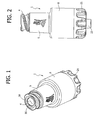
Figure 1 is a schematic perspective view of a valve connector for medical lines according to a first embodiment of the invention; -
Figure 2 is a view of the valve connector in elevation; -
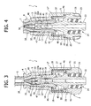
Figure 3 is a schematic view in axial cross section of the valve connector represented in a first condition; -
Figure 4 is a view similar to that ofFigure 3 but rotated through 90°; -
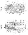
Figures 5-6 ,7-8 ,9-10 and11-12 are views similar to those ofFigures 3 and 4 , respectively, which illustrate the valve connector in different successive operating conditions; -
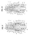
Figure 13 shows in axial cross section a first component of the valve connector; -
Figure 14 is a perspective view from beneath of the component ofFigure 13 ; -
Figure 15 is a plan view from beneath of the component ofFigure 13 ; -
Figure 16 is a perspective view of a second component of the tubular connector; -
Figure 17 is a perspective view of a third component of the tubular connector; -
Figure 18 is a view in elevation of the component ofFigure 17 ; -
Figure 19 is an axial cross-sectional view of the component ofFigure 18 ; -
Figure 20 is a view in elevation of a variant of the valve connector according to the invention; -
Figure 21 is an axial cross-sectional view of the variant ofFigure 20 ; -
Figure 22 is a perspective view of the variant ofFigure 21 ; -
Figure 23 is a perspective view from above of the second component of the valve connector according toFigures 20-22 ; -
Figure 24 is a perspective view from beneath of the component ofFigure 23 ; -
Figure 25 is an axial cross-sectional view of the second component ofFigures 23 and 24 ; and -
Figure 26 is a perspective view from beneath of the first component of the valve connector according toFigures 20-22 . - The first embodiment of the valve connector for medical infusion lines according to the invention, represented in
Figures 1 to 19 , basically comprises three components: an externaltubular body 1, an internalhollow spike 2, set axially within the cavity of thetubular body 1, and anelastic sealing member 3. Typically, thetubular body 1 and thehollow spike 2 are made of rigid moulded plastic material, whilst the sealingmember 3 is made of an elastic material, for example silicone rubber. - As is illustrated in detail in
Figures 13 to 15 , thetubular body 1 has aninlet end 4 formed like a female luer-lock connection member for engagement, in a generally conventional way, with a male luer-lock connection member of an introducer for fluid, constituted, for example, by a needleless syringe, a part of which is designated as a whole by S inFigures 3 and11 . Theinlet end 4 is connected to a generally cylindricalintermediate portion 5, followed by a final widenedportion 6, which is also generally cylindrical. - The internal surface of the
inlet end 4 has an initialcylindrical part 7 formed with a series ofaxial channels 8 and radiused to a portion having the shape of atruncated cone 9. The internal surface of theintermediate part 5 has, in succession, towards thefinal portion 6, a firstcylindrical portion 10, a portion having the shape of atruncated cone 11, a secondcylindrical portion 12, a portion having the shape of atruncated cone 13, a thirdcylindrical portion 14, a portion having the shape of atruncated cone 15, and a fourthcylindrical portion 16 terminating with a ring of frontaxial projections 17 facing the inside of the enlargedterminal portion 6. The internal surface of the latter is in turn formed with a ring ofaxial projections 18 projecting radially, the free ends of which define an annular shoulder designated by 27, the function of which will be clarified in what follows. - The cavity of the
tubular body 1 is designated as a whole by 19. - The
hollow spike 2, illustrated in greater detail inFigure 16 , has a base designated as a whole by 20, formed on the outside with a grippingring 21 and shaped internally like a male luer-lock connection member with a centraltubular shank 22 having a slightly conical outer surface and an internally threadedexternal shell 23. The connection member 22-23 defines the outlet end of thevalve connector 1, designated as a whole by 24. - The
base 20 is formed with a firstannular flange 25 of larger diameter, for joining the edge of the free end of the widenedterminal portion 6 of thetubular body 1, fixed in the way represented inFigures 3-12 , and an annular flange ofsmaller diameter 26, the function of which will also be clarified in what follows. Branching off in an integral way from saidannular flange 26 is atubular post 28, preferably but not necessarily coaxial to theshank 22 and in communication with this, including an initial portion within aconical surface 29, divergent towards the outlet end 24 of the connector, followed by acylindrical portion 30 formed with one, two or more side holes 31, for example in the form of axially elongated slots. Thecylindrical portion 30 has, at its free end, a closed tip 32 (clearly visible inFigures 3 to 12 ) facing theinlet end 4 of thetubular body 1 and situated at a certain axial distance therefrom. Projecting from the closedtip 32 is a ring of radialaxial projections 33 set at angular distances apart so as to define between them axial-radial channels offlow 34. The end surfaces of theprojections 33 facing theinlet end 4 are preferably plane or slightly rounded. - Formed underneath the
closed tip 32 is a conicalannular surface 32a. - The sealing
member 3 is illustrated in detail inFigures 17 to 19 . It comprises, in a single piece, anelastic head 35, an elastichollow element 36, and anelastic base 37. The general shape of the sealingmember 3, and in particular its external conformation, corresponds substantially to that of thecavity 19 of thetubular body 1, within which it is housed. Thus, theelastic head 35 has a cylindrical outer surface complementary to theinternal surface 7 of theinlet end 4 in such a way as to enable housing thereof, in the way represented inFigures 3 and 4 , with slight radial play, i.e., without substantial interference, in a condition of closing in which saidhead 35 is substantially undeformed. - Formed through the
head 35 is a pre-slit oraxial notch 38, which, in the undeformed condition of closing of theelastic head 35 within theinlet end 4, is maintained gripped as a result of the elasticity of thehead 35. In said condition, an anti-bacterial protection barrier is formed between the inside of the valve connector and the outside, ensuring at the time same the possibility of an effective cleaning conventionally performed by means of a swab soaked in a disinfectant. - The
head 35 is connected to the elastichollow element 36 through a portion having the shape of atruncated cone 39, complementary to theconical surface 9 of thetubular body 1. The outer surface of the elastichollow element 36 in turn has a firstcylindrical portion 40, which is radiused to a secondcylindrical portion 41 through a portion having the shape of atruncated cone 42. The secondcylindrical portion 41 is radiused in turn to theelastic base 37 through a portion having the shape of atruncated cone 43, followed by acylindrical portion 44. Theportions portions tubular body 1. - The
elastic base 37 has a general cylindrical shape, the external diameter of which substantially corresponds to that defined by the ring of internalaxial projections 18 of theterminal portion 6 of thetubular body 1. Saidelastic base 37 is radiused to thecylindrical portion 44 of the elastichollow element 36 through a generallytransverse wall 45, which, in the undeformed condition of the sealingmember 3 represented inFigures 17 to 19 , has the shape of a truncated cone. - The
elastic base 37 terminates, on the side opposite to theelastic head 35, with an externalannular flange 46 by means of which saidelastic base 37 is gripped and blocked axially in a fluid-tight way between theannular shoulders base 25 of thehollow spike 2 and of theterminal part 6 of thetubular body 1, in the way represented inFigures 3 to 12 . - The
elastic base 37 and thetransverse wall 45 preferably have a wall thickness generally smaller than that of the remaining part of the sealingmember 3. - Internally, the sealing
member 3 is formed with a firstannular projection 47 and with a secondannular projection 48, set at axial distances apart from one another and designed to define, with the modalities clarified in what follows, a first fluid-tight member and a second fluid-tight member, respectively. - In the assembled condition of the valve connector according to the invention, the
tubular body 1 is fixed to thehollow spike 2, as has been said, in a position corresponding to theannular flange 25 of thebase 20 of the latter, with thetubular post 28 that extends coaxially within thecylindrical part 5. The sealingmember 3 is in turn contained within thetubular body 1 with theelastic head 35 set, in the way clarified previously, within theinlet end 4, the elastichollow element 36 housed within thecylindrical part 5 so as to surround thetubular post 28 of thehollow spike 2, and theelastic base 37 housed within theterminal portion 6 of thetubular body 1. As has been said, theannular end flange 46 of theelastic base 37 is gripped axially between theshoulders hollow spike 2 and of thetubular body 1, respectively, with the wall of said elastic base resting against the ring ofaxial ribbings 18. Thetransverse wall 45 is adjacent to the ring offront projections 17, so as to be slightly deformed elastically in a generally plane, i.e., radial, condition (represented inFigures 3 and 4 ). The first internal fluid-tight member 47 of the sealingmember 3 is set in fluid-tight contact against theconical surface 32a of thetip 32 of thehollow spike 2, thanks to the interaction between the outercylindrical surfaces hollow element 36 and the complementary innercylindrical surfaces hollow body 1, whilst the second fluid-tight member 48 is set in fluid-tight contact against the area of smaller diameter of theconical part 29, thanks to the interaction between the outercylindrical surface 44 of the elastichollow element 36 and the complementary innercylindrical surface 14 of thehollow body 1. The elastichollow element 36 and theelastic head 35 of the sealingmember 3 are normally kept in a condition of slight axial preloading within thetubular body 1, and the side holes 31 of thehollow spike 2 are isolated hermetically with respect to theinlet end 4 of the connector, communication of which with theoutlet end 24 being thus closed. - Between the
elastic base 37 and thewall 35 on the one hand, and the part having the shape of atruncated cone 29 of thehollow spike 2 on the other, there is thus defined anannular chamber 50, which communicates with the outside of the valve connector through one ormore passages 51 formed in thebase 20 of thehollow spike 2. - Since the
annular chamber 50 is in communication with the outside through thepassages 51, the pressure inside it is evidently atmospheric pressure. - The condition described above corresponds to fluid-tight closing of the valve connector.
- When the end of the needleless syringe or introducer S is resting at the front against the
elastic head 35 and hence inserted within theinlet connector 4, in the way represented inFigures 3 and 4 , theelastic head 35 is pushed axially towards the inside of the connector thanks to the elastic deformation of the sealingmember 3 and, more in particular, to the deflection of thewall 45 of theelastic base 37 within theannular chamber 50. - Proceeding with insertion of the introducer S, the
wall 45 continues to undergo deflection within theannular chamber 50, undergoing progressive deformation due to tensile stress in the way represented respectively inFigures 5-6 ,7-8 and9-10 , in which the introducer S has been omitted for reasons of simplicity of illustration. - As a result of the deflection due to tensile stress of the
wall 45, theelastic base 37 is compressed and tends, in the area of radiusing with thewall 45, designated as a whole by 45a inFigure 19 , to "roll up" towards the inside of theannular chamber 50, in the way represented schematically inFigures 7-8 ,9-10 and11-12 . - The
elastic head 35 and the elastichollow element 36 of the sealingmember 3 then slide progressively within thetubular body 1 and along thetubular post 28 of thehollow spike 2 in such a way that the first fluid-tight member 47 moves away from theconical surface 32a of thetip 32, whilst the second fluid-tight member 48 slides in a fluid-tight way along theconical part 29. - Simultaneously, the
projections 33 of thehollow spike 2 start to interact from inside with theelastic head 35, which (Figures 9 and 10 ) starts to assume an elastically deformed configuration, namely, radially dilated towards the outside, so as to start to open the pre-slit 38. - Following upon complete insertion of the introducer S (
Figures 11 and 12 ), the pre-slit 38 is completely opened, whilst the first fluid-tight member 47 sets itself underneath the side holes 31 of thehollow spike 2. The second fluid-tight member 48 has displaced slidably up to the area of larger diameter of theconical part 29 of thehollow spike 2, and thewall 45 is completely deflected and stretched within theannular chamber 50. The valve connector is thus in an opening condition, with the inlet end 4 (and hence the introducer S) in communication with theoutlet end 24 through the pre-slit 38, the axial-radial channels 34, the side holes 31, thetubular post 28, and theshank 22. - When the introducer S is extracted from the
inlet end 4, the elastic return of thewall 45 and of the sealingmember 3 as a whole promptly restores the configuration of closing of the valve connector, in which theelastic head 35 returns into the undeformed condition within theinlet end 4, reclosing the pre-slit 38, and the side holes 31 are again isolated by the fluid-tight members -
Figures 20 to 26 illustrate a variant of the valve connector according to the invention. In said variant, in which parts that are identical or similar to the ones already described previously are designated by the same reference numbers, thetubular body 1 of the valve connector is provided with a tubularside wye connector 55. Saidside connector 55 is formed integrally with the terminalcylindrical portion 6 of thetubular body 1, substantially at the height of thebase 20 of thetubular spike 2. Thebase 20 is formed with acircumferential groove 56 closed on the outside in a fluid-tight way by the wall of said cylindricalterminal portion 6, which in this variant has an axial extension slightly greater than that of the preceding embodiment. Thegroove 56 thus defines an annular chamber, which on the one hand communicates with theside connector 55 through ahole 57, and on the other is connected with the cavity of thespike 2 and with theshank 22, i.e., with the outlet end 24 of the connector, through one or moreradial passages 58. - Operation of the valve connector with the
wye connector 55 is altogether identical to what was described previously with reference toFigures 3 to 12 . - In both of the embodiments described above, the valve connector according to the invention presents, as compared to similar known valve connectors, a series of important advantages: an improved degree of reliability in terms of prompt return of the sealing member into the closed condition even following upon repeated opening; appreciably reduced overall axial dimensions; fabrication with a minimal number of parts, which can be produced in a relatively simple and inexpensive way; capacity of ensuring the substantial absence of overpressures or negative pressure inside the valve connector during the steps of transition between the condition of opening and that of closing.
- Of course the details of construction and the embodiments may vary widely with respect to what is described and illustrated herein, without thereby departing from the scope of the present invention, as defined in the ensuing claims.
Claims (19)
- A valve connector for medical lines for infusion by means of an introducer of fluid (S), comprising:- a tubular body having a cavity (19), an inlet end (4) provided for engagement of an introducer (S), and an outlet end (24);- a hollow spike (2) set axially within the cavity of the tubular body (1) and having a closed tip (32) facing said inlet end (4) of the tubular body (1) and set at an axial distance therefrom, said hollow spike (2) being in communication with said outlet end (24) and having at least one side hole (31) set at a distance from said closed tip (32) for communication with the cavity (19) of said tubular body (1); and- a sealing member (3) including:- an elastic head (35) having a pre-slit (38) and normally set in a closed condition within said inlet end (4) of the tubular body (1), in which said pre-slit (38) is closed, said elastic head (35) being displaceable axially against said closed tip (32) of the hollow spike (2) as a result of insertion of said introducer (S) within said inlet end (4), for interacting with said closed tip (32), assuming an elastically deformed condition of opening of said pre-slit (38);- an elastic hollow element (36) joined to said head (35), set between said tubular body (1) and said hollow spike (2) and having sealing means (47, 48) in contact with said hollow spike (2) for isolating said at least one side hole (31) from the cavity of the tubular body (1) when said head (35) is set in the aforesaid undeformed closed condition, said elastic hollow element (36) including an elastic thrust means (36, 45) tending to maintain said head (35) in said closed condition,said valve connector being characterized in that said elastic thrust means comprises a base part (37) of said sealing member (3) having a generally cylindrical axial wall, set at a radial distance from said hollow spike (2) so as to define therewith an annular chamber (50), said base part (37) being joined to said elastic hollow element (36) through a generally transverse annular wall (45), which, during the axial displacement of said elastic head (35) from .said condition of closing to said condition of opening, bends within said annular chamber (50).
- The valve connector according to Claim 1, characterized in that said generally transverse wall (45) bends undergoing deformation due to tensile stress.
- The valve connector according to Claim 1, characterized in that said sealing means of said elastic hollow element (36) of the sealing member (3) comprise a first internal annular projection (47) and a second internal annular projection (48), set at axial distances apart from one another and arranged on opposite sides with respect to said at least one side hole (31) of the hollow spike (2) in the aforesaid condition of closing of said elastic head (35).
- The valve connector according to Claim 3, characterized in that said first annular projection (47) is kept, in said condition of closing of the elastic head (35), in fluid-tight contact against an annular projection within a conical surface (32a), formed in the proximity of said closed tip (32) of said hollow spike (2).
- The valve connector according to Claim 3, characterized in that said second internal annular projection (48) is set in fluid-tight sliding contact against a portion within a conical surface (29) of said hollow spike (2), which delimits internally said annular chamber (50) and is divergent towards said outlet end (24) of the connector.
- The valve connector according to Claim 1, characterized in that said annular chamber (50) communicates with the outside of the connector.
- The valve connector according to Claim 5, characterized in that said base part (37) of the elastic thrust means of said sealing member (3) is blocked axially between said tubular body (1) and a base part (20) of said hollow spike (2).
- The valve connector according to Claim 1, characterized in that said elastic head (35) of the sealing member (3) is set, in said condition of closing, substantially without interference within said inlet end (4) of the tubular body (1).
- The valve connector according to Claim 8, characterized in that said inlet end (4) of the tubular body (1) has an internal wall (7) formed with axial channels (8).
- The valve connector according to Claim 1, characterized in that said elastic hollow element (36) of the sealing member (3) has an outer wall with axial portions having a cylindrical surface (40, 41, 44) connected to one another by portions having the shape of a truncated cone, and in that said tubular body (1) has, in the area corresponding to said elastic hollow element (36), an internal surface of complementary shape.
- The valve connector according to Claim 1, characterized in that said generally transverse annular wall (45) of the sealing member (3) has a thickness that is substantially smaller than that of said elastic hollow element (36).
- The valve connector according to Claim 1, characterized in that said base part (37) of the sealing member (3) is housed within a widened cylindrical portion (6) of said tubular body (1) formed with a ring of axial projections (18) projecting radially towards said base part (37).
- The valve connector according to Claim 12, characterized in that said widened cylindrical portion (6) of the tubular body (1) is formed with a ring of axial projections (17) projecting at the front towards said generally transverse annular wall (45) of said sealing member (3).
- The valve connector according to Claim 1, characterized in that said closed tip (32) of said hollow spike (2) is shaped so as to cause said elastic head (35) of the sealing member (3) to assume said condition of opening without traversal of said pre-slit (38).
- The valve connector according to Claim 14, characterized in that said closed tip (32) of said hollow spike (2) has a plurality of axial projections (33) set at angular distances apart from one another and delimiting channels of flow (34) facing said inlet end (4) of the tubular body (1).
- The valve connector according to Claim 1, characterized in that said outlet end (24) consists of a male luer-lock connection element (22, 23) formed integrally with said hollow spike (2).
- The valve connector according to one or more of the preceding claims, characterized in that said tubular body (1) is formed with a tubular side wye connector (55).
- The valve connector according to Claim 17, characterized in that said tubular wye connector (55) communicates with said outlet end (24) of the connector through an annular chamber (56) in communication with the inside of said hollow spike (2) downstream of said at least one side hole (31).
- The valve connector according to Claim 18, characterized in that said annular chamber is formed by a circumferential groove (56) of an enlarged portion (20) of said hollow spike (2) closed on the outside by said tubular body (1) and connected to said outlet end of the connector (24) through at least one radial passage of said enlarged portion (20).
Applications Claiming Priority (1)
| Application Number | Priority Date | Filing Date | Title |
|---|---|---|---|
| IT000206A ITTO20060206A1 (en) | 2006-03-17 | 2006-03-17 | VALVE VALVE FOR MEDICAL LINES |
Publications (2)
| Publication Number | Publication Date |
|---|---|
| EP1834665A1 EP1834665A1 (en) | 2007-09-19 |
| EP1834665B1 true EP1834665B1 (en) | 2010-02-17 |
Family
ID=38518483
Family Applications (1)
| Application Number | Title | Priority Date | Filing Date |
|---|---|---|---|
| EP07104236A Active EP1834665B1 (en) | 2006-03-17 | 2007-03-15 | A valve connector for medical lines |
Country Status (12)
| Country | Link |
|---|---|
| US (1) | US8048038B2 (en) |
| EP (1) | EP1834665B1 (en) |
| CN (1) | CN101152594B (en) |
| AT (1) | ATE457772T1 (en) |
| AU (1) | AU2007201164B8 (en) |
| CA (1) | CA2581547C (en) |
| DE (1) | DE602007004754D1 (en) |
| ES (1) | ES2341040T3 (en) |
| IT (1) | ITTO20060206A1 (en) |
| PT (1) | PT1834665E (en) |
| SG (1) | SG136057A1 (en) |
| ZA (1) | ZA200702197B (en) |
Cited By (1)
| Publication number | Priority date | Publication date | Assignee | Title |
|---|---|---|---|---|
| US9586037B2 (en) | 2009-11-26 | 2017-03-07 | Industrie Borla S.P.A. | Valved male luer connector |
Families Citing this family (55)
| Publication number | Priority date | Publication date | Assignee | Title |
|---|---|---|---|---|
| US6695817B1 (en) | 2000-07-11 | 2004-02-24 | Icu Medical, Inc. | Medical valve with positive flow characteristics |
| US7753892B2 (en) | 2001-11-13 | 2010-07-13 | Nypro Inc. | Anti-drawback medical valve |
| US7837658B2 (en) | 2001-11-13 | 2010-11-23 | Nypro Inc. | Anti-drawback medical valve |
| US7914502B2 (en) | 2003-07-31 | 2011-03-29 | Nypro Inc. | Anti-drawback medical valve |
| WO2006052655A2 (en) | 2004-11-05 | 2006-05-18 | Icu Medical, Inc. | Soft-grip medical connector |
| CA2649438A1 (en) | 2006-04-11 | 2007-10-25 | Nypro Inc. | Medical valve with moving member and method |
| BRPI0714767A2 (en) | 2006-08-11 | 2013-07-16 | Nypro Inc | Expansion Element Medical Valve |
| CA2644187A1 (en) | 2007-12-05 | 2009-06-05 | Tyco Healthcare Group Lp | Device for reducing microbial contamination |
| ITTO20080059A1 (en) * | 2008-01-29 | 2009-07-30 | Industrie Borla Spa | VALVE VALVE FOR MEDICAL LINES |
| EP2259839B1 (en) * | 2008-03-04 | 2015-12-23 | Infusion Innovations, Inc. | Devices, assemblies, and methods for controlling fluid flow |
| ITTO20080381A1 (en) | 2008-05-21 | 2009-11-22 | Industrie Borla Spa | VALVE VALVE FOR MEDICAL LINES |
| IT1392847B1 (en) * | 2009-01-14 | 2012-03-23 | Borla Ind | VALVE VALVE FOR MEDICAL LINES |
| US8469928B2 (en) * | 2009-02-11 | 2013-06-25 | Becton, Dickinson And Company | Systems and methods for providing a flushable catheter assembly |
| US8757590B2 (en) * | 2009-03-22 | 2014-06-24 | Elcam Medical Agricultural Cooperative Association Ltd. | Closed male luer connector |
| US8454579B2 (en) | 2009-03-25 | 2013-06-04 | Icu Medical, Inc. | Medical connector with automatic valves and volume regulator |
| ES2696987T3 (en) | 2009-06-22 | 2019-01-21 | Np Medical Inc | Medical valve with improved backpressure seal |
| TR200906911A1 (en) * | 2009-09-08 | 2010-12-21 | Asset Medi̇kal Tasarim Sanayi̇ Ve Ti̇caret Anoni̇m Şi̇rketi̇ | Cleanable needle-free valve. |
| USD644731S1 (en) | 2010-03-23 | 2011-09-06 | Icu Medical, Inc. | Medical connector |
| US8298196B1 (en) * | 2010-03-24 | 2012-10-30 | Mansour George M | Needleless access connector and method of use |
| US8758306B2 (en) | 2010-05-17 | 2014-06-24 | Icu Medical, Inc. | Medical connectors and methods of use |
| US9138572B2 (en) | 2010-06-24 | 2015-09-22 | Np Medical Inc. | Medical valve with fluid volume alteration |
| KR20140042783A (en) * | 2011-02-15 | 2014-04-07 | 체베에스-보코 서플라이 아게 | Valve for liquid vessels |
| EP2554214A1 (en) | 2011-08-04 | 2013-02-06 | B. Braun Melsungen AG | Needle free connector with a collapsible resilient membrane fitting and corresponding method |
| US8777931B2 (en) | 2011-08-19 | 2014-07-15 | Alcon Research, Ltd. | Retractable luer lock fittings |
| ITTO20120056A1 (en) * | 2012-01-24 | 2013-07-25 | Borla Ind | CONNECTOR FOR MEDICAL LINES OF INFUSION, TRANSFUSION AND THE LIKE |
| JP2014117461A (en) * | 2012-12-17 | 2014-06-30 | Fukai Kogyo Kk | Coinjection tube |
| US9308362B2 (en) | 2013-03-12 | 2016-04-12 | Carefusion 303, Inc. | Male luer with fluid path and vent path seals |
| US9144672B2 (en) | 2013-03-13 | 2015-09-29 | Carefusion 303, Inc. | Needleless connector with compressible valve |
| US9089682B2 (en) | 2013-03-14 | 2015-07-28 | Carefusion 303, Inc. | Needleless connector with support member |
| ITTO20130433A1 (en) * | 2013-05-29 | 2014-11-30 | Borla Ind | CONNECTOR FOR MEDICAL LINES |
| ITMO20130264A1 (en) * | 2013-09-25 | 2015-03-26 | Giuseppe Maffei | CONNECTOR WITHOUT NEEDLE |
| AU2014364218B2 (en) | 2013-12-11 | 2019-06-06 | Icu Medical, Inc. | Check valve |
| CA2936970C (en) | 2014-01-31 | 2021-08-24 | Industrie Borla S.P.A. | "valved connector for medical lines" |
| DE102014214076A1 (en) | 2014-07-18 | 2016-01-21 | Hamilton Bonaduz Ag | A fluid conduit assembly comprising a plurality of fluid conduit elements, valve conduit assembly, comprising a fluid conduit assembly and a switching assembly, and a handle assembly having a valve conduit assembly |
| WO2016077575A1 (en) * | 2014-11-12 | 2016-05-19 | Rymed Technologies, Llc | Needleless, intermittent, neutral displacement iv injection port |
| USD786427S1 (en) | 2014-12-03 | 2017-05-09 | Icu Medical, Inc. | Fluid manifold |
| USD793551S1 (en) | 2014-12-03 | 2017-08-01 | Icu Medical, Inc. | Fluid manifold |
| TWI584837B (en) * | 2015-02-09 | 2017-06-01 | 怡安醫療器材股份有限公司 | Needleless luer access connector module |
| ITUB20152902A1 (en) | 2015-08-05 | 2017-02-05 | Borla Ind | VALVE VALVE FOR MEDICAL LINES |
| AU367143S (en) * | 2015-08-05 | 2016-02-15 | Borla Ind | Valved connector for medical lines |
| EP3011994B1 (en) * | 2015-08-10 | 2018-10-10 | Cair L. G. L. | Female luer connector |
| EP3517164B1 (en) * | 2016-09-26 | 2021-09-08 | Terumo Kabushiki Kaisha | Male connector, medical instrument, and connection method |
| CN106581789B (en) * | 2016-12-12 | 2023-05-26 | 武汉维斯第医用科技股份有限公司 | External multi-pipeline converter for negative pressure closed drainage system |
| WO2018127366A1 (en) * | 2017-01-09 | 2018-07-12 | Fresenius Kabi Deutschland Gmbh | Connector assembly for connecting medical lines to each other |
| KR20180085930A (en) * | 2017-01-20 | 2018-07-30 | 삼성전자주식회사 | Waterproofing device |
| JP6924368B2 (en) * | 2017-05-26 | 2021-08-25 | 株式会社ジェイ・エム・エス | Male connector |
| DE102017210795A1 (en) * | 2017-06-27 | 2018-12-27 | B. Braun Melsungen Ag | Medical fluid connection device |
| US11224555B2 (en) | 2018-04-23 | 2022-01-18 | Hospira, Inc. | Access and vapor containment system for a drug vial and method of making and using same |
| US20200316359A1 (en) * | 2019-04-04 | 2020-10-08 | Becton, Dickinson And Company | Multi-use blood control catheter assembly |
| JP7389311B2 (en) * | 2019-06-27 | 2023-11-30 | 株式会社トップ | female connector |
| IL282356A (en) * | 2021-04-14 | 2022-11-01 | Equashield Medical Ltd | Devices for use in drug delivery systems |
| CN113607192B (en) * | 2021-09-30 | 2021-12-14 | 武汉长盈通光电技术股份有限公司 | Indirect connection type optical fiber gyro assembly testing device |
| US20240151339A1 (en) * | 2022-11-08 | 2024-05-09 | Carefusion 303, Inc. | Fluid connector assembly with neutral fluid displacement that limits connector damage |
| EP4445941A1 (en) | 2023-04-12 | 2024-10-16 | Industrie Borla S.p.A. | Valve connector for medical lines |
| CN116570831B (en) * | 2023-06-30 | 2024-01-05 | 江苏康进医疗器材有限公司 | Quick joint for catheter |
Family Cites Families (19)
| Publication number | Priority date | Publication date | Assignee | Title |
|---|---|---|---|---|
| EP0988871B1 (en) | 1991-12-18 | 2004-03-24 | ICU Medical, Inc. | Method of transferring fluid |
| US5242342A (en) | 1992-07-07 | 1993-09-07 | Bi-Robic Conditioning Systems, Inc. | Aerobic and isometric exercise apparatus |
| US5699821A (en) * | 1993-10-13 | 1997-12-23 | Paradis; Joseph R. | Control of fluid flow |
| US5439451A (en) * | 1994-03-22 | 1995-08-08 | B. Braun Medical, Inc. | Capless medical backcheck valve |
| US5820601A (en) * | 1994-06-20 | 1998-10-13 | Critical Device Corporation | Needleless injection site |
| US5514116A (en) * | 1994-10-24 | 1996-05-07 | Vlv Associates | Connector |
| NZ286445A (en) * | 1995-05-16 | 1997-12-19 | Ivac Corp | Needleless luer connector: deformable piston occludes bore |
| US5700248A (en) | 1995-12-15 | 1997-12-23 | Icu Medical, Inc. | Medical valve with tire seal |
| US6079432A (en) * | 1996-07-02 | 2000-06-27 | Paradis; Joseph R. | Control of fluid flow by oval shaped valve member containing a cam interface |
| DE69728422T2 (en) * | 1996-11-18 | 2005-03-03 | Nypro Inc., Clinton | WASHABLE LOWER VALVE |
| US6050978A (en) * | 1997-05-09 | 2000-04-18 | Becton Dickinson And Company | Needleless valve connector |
| US6706022B1 (en) | 1999-07-27 | 2004-03-16 | Alaris Medical Systems, Inc. | Needleless medical connector with expandable valve mechanism |
| US6755391B2 (en) * | 2000-10-23 | 2004-06-29 | Nypro Inc. | Anti-drawback medical valve |
| JP2005500142A (en) * | 2001-08-22 | 2005-01-06 | ナイプロ・インク | Medical valve with expansion member |
| CN1230225C (en) * | 2001-08-23 | 2005-12-07 | 医疗器械创新有限公司 | Valve for use with syringe and which prevents backflow |
| US6802490B2 (en) * | 2001-11-29 | 2004-10-12 | Alaris Medical Systems, Inc. | Needle free medical connector with expanded valve mechanism and method of fluid flow control |
| US7914502B2 (en) * | 2003-07-31 | 2011-03-29 | Nypro Inc. | Anti-drawback medical valve |
| ITTO20040524A1 (en) * | 2004-07-27 | 2004-10-27 | Borla Ind | VALVE CONNECTOR FOR MEDICAL INFUSION LINES |
| US7296782B2 (en) * | 2004-10-01 | 2007-11-20 | Halkey-Roberts Corporation | Dome check valve |
-
2006
- 2006-03-17 IT IT000206A patent/ITTO20060206A1/en unknown
-
2007
- 2007-03-08 SG SG200701720-5A patent/SG136057A1/en unknown
- 2007-03-12 CA CA2581547A patent/CA2581547C/en active Active
- 2007-03-15 PT PT07104236T patent/PT1834665E/en unknown
- 2007-03-15 EP EP07104236A patent/EP1834665B1/en active Active
- 2007-03-15 DE DE602007004754T patent/DE602007004754D1/en active Active
- 2007-03-15 ZA ZA2007/02197A patent/ZA200702197B/en unknown
- 2007-03-15 ES ES07104236T patent/ES2341040T3/en active Active
- 2007-03-15 AT AT07104236T patent/ATE457772T1/en not_active IP Right Cessation
- 2007-03-16 AU AU2007201164A patent/AU2007201164B8/en active Active
- 2007-03-16 US US11/687,188 patent/US8048038B2/en active Active
- 2007-03-16 CN CN2007101676346A patent/CN101152594B/en active Active
Cited By (1)
| Publication number | Priority date | Publication date | Assignee | Title |
|---|---|---|---|---|
| US9586037B2 (en) | 2009-11-26 | 2017-03-07 | Industrie Borla S.P.A. | Valved male luer connector |
Also Published As
| Publication number | Publication date |
|---|---|
| AU2007201164A1 (en) | 2007-10-04 |
| CA2581547C (en) | 2010-07-27 |
| AU2007201164B2 (en) | 2008-08-28 |
| SG136057A1 (en) | 2007-10-29 |
| CA2581547A1 (en) | 2007-09-17 |
| CN101152594A (en) | 2008-04-02 |
| AU2007201164B8 (en) | 2008-11-27 |
| ITTO20060206A1 (en) | 2007-09-18 |
| EP1834665A1 (en) | 2007-09-19 |
| US8048038B2 (en) | 2011-11-01 |
| ES2341040T3 (en) | 2010-06-14 |
| ATE457772T1 (en) | 2010-03-15 |
| PT1834665E (en) | 2010-04-26 |
| ZA200702197B (en) | 2008-08-27 |
| US20070218757A1 (en) | 2007-09-20 |
| CN101152594B (en) | 2010-10-27 |
| DE602007004754D1 (en) | 2010-04-01 |
Similar Documents
| Publication | Publication Date | Title |
|---|---|---|
| EP1834665B1 (en) | A valve connector for medical lines | |
| CA2665722C (en) | Valve connector for medical lines | |
| EP1773445B1 (en) | Valve connector for medical infusion lines | |
| EP2331185B1 (en) | Luer activated medical connector having a low priming volume | |
| US5921264A (en) | Swabbable needleless valve | |
| US20040172006A1 (en) | Needleless Luer activated medical connector | |
| JP2005515871A (en) | Wipeable slit valve | |
| JP4526549B2 (en) | Medical line valve connector | |
| AU2016304445B2 (en) | Valve connector for medical lines | |
| US20240342370A1 (en) | Valve connector for medical lines | |
| NZ739087B2 (en) | Valve connector for medical lines |
Legal Events
| Date | Code | Title | Description |
|---|---|---|---|
| PUAI | Public reference made under article 153(3) epc to a published international application that has entered the european phase |
Free format text: ORIGINAL CODE: 0009012 |
|
| AK | Designated contracting states |
Kind code of ref document: A1 Designated state(s): AT BE BG CH CY CZ DE DK EE ES FI FR GB GR HU IE IS IT LI LT LU LV MC MT NL PL PT RO SE SI SK TR |
|
| AX | Request for extension of the european patent |
Extension state: AL BA HR MK YU |
|
| 17P | Request for examination filed |
Effective date: 20071227 |
|
| AKX | Designation fees paid |
Designated state(s): AT BE BG CH CY CZ DE DK EE ES FI FR GB GR HU IE IS IT LI LT LU LV MC MT NL PL PT RO SE SI SK TR |
|
| GRAP | Despatch of communication of intention to grant a patent |
Free format text: ORIGINAL CODE: EPIDOSNIGR1 |
|
| GRAS | Grant fee paid |
Free format text: ORIGINAL CODE: EPIDOSNIGR3 |
|
| GRAA | (expected) grant |
Free format text: ORIGINAL CODE: 0009210 |
|
| AK | Designated contracting states |
Kind code of ref document: B1 Designated state(s): AT BE BG CH CY CZ DE DK EE ES FI FR GB GR HU IE IS IT LI LT LU LV MC MT NL PL PT RO SE SI SK TR |
|
| REG | Reference to a national code |
Ref country code: GB Ref legal event code: FG4D |
|
| REG | Reference to a national code |
Ref country code: CH Ref legal event code: EP |
|
| REG | Reference to a national code |
Ref country code: IE Ref legal event code: FG4D |
|
| REF | Corresponds to: |
Ref document number: 602007004754 Country of ref document: DE Date of ref document: 20100401 Kind code of ref document: P |
|
| REG | Reference to a national code |
Ref country code: PT Ref legal event code: SC4A Free format text: AVAILABILITY OF NATIONAL TRANSLATION Effective date: 20100420 |
|
| REG | Reference to a national code |
Ref country code: NL Ref legal event code: T3 |
|
| REG | Reference to a national code |
Ref country code: SE Ref legal event code: TRGR |
|
| REG | Reference to a national code |
Ref country code: ES Ref legal event code: FG2A Ref document number: 2341040 Country of ref document: ES Kind code of ref document: T3 |
|
| LTIE | Lt: invalidation of european patent or patent extension |
Effective date: 20100217 |
|
| PG25 | Lapsed in a contracting state [announced via postgrant information from national office to epo] |
Ref country code: IS Free format text: LAPSE BECAUSE OF FAILURE TO SUBMIT A TRANSLATION OF THE DESCRIPTION OR TO PAY THE FEE WITHIN THE PRESCRIBED TIME-LIMIT Effective date: 20100617 Ref country code: LT Free format text: LAPSE BECAUSE OF FAILURE TO SUBMIT A TRANSLATION OF THE DESCRIPTION OR TO PAY THE FEE WITHIN THE PRESCRIBED TIME-LIMIT Effective date: 20100217 |
|
| PG25 | Lapsed in a contracting state [announced via postgrant information from national office to epo] |
Ref country code: SI Free format text: LAPSE BECAUSE OF FAILURE TO SUBMIT A TRANSLATION OF THE DESCRIPTION OR TO PAY THE FEE WITHIN THE PRESCRIBED TIME-LIMIT Effective date: 20100217 Ref country code: PL Free format text: LAPSE BECAUSE OF FAILURE TO SUBMIT A TRANSLATION OF THE DESCRIPTION OR TO PAY THE FEE WITHIN THE PRESCRIBED TIME-LIMIT Effective date: 20100217 Ref country code: LV Free format text: LAPSE BECAUSE OF FAILURE TO SUBMIT A TRANSLATION OF THE DESCRIPTION OR TO PAY THE FEE WITHIN THE PRESCRIBED TIME-LIMIT Effective date: 20100217 Ref country code: FI Free format text: LAPSE BECAUSE OF FAILURE TO SUBMIT A TRANSLATION OF THE DESCRIPTION OR TO PAY THE FEE WITHIN THE PRESCRIBED TIME-LIMIT Effective date: 20100217 Ref country code: AT Free format text: LAPSE BECAUSE OF FAILURE TO SUBMIT A TRANSLATION OF THE DESCRIPTION OR TO PAY THE FEE WITHIN THE PRESCRIBED TIME-LIMIT Effective date: 20100217 |
|
| PG25 | Lapsed in a contracting state [announced via postgrant information from national office to epo] |
Ref country code: RO Free format text: LAPSE BECAUSE OF FAILURE TO SUBMIT A TRANSLATION OF THE DESCRIPTION OR TO PAY THE FEE WITHIN THE PRESCRIBED TIME-LIMIT Effective date: 20100217 Ref country code: CY Free format text: LAPSE BECAUSE OF FAILURE TO SUBMIT A TRANSLATION OF THE DESCRIPTION OR TO PAY THE FEE WITHIN THE PRESCRIBED TIME-LIMIT Effective date: 20100217 Ref country code: GR Free format text: LAPSE BECAUSE OF FAILURE TO SUBMIT A TRANSLATION OF THE DESCRIPTION OR TO PAY THE FEE WITHIN THE PRESCRIBED TIME-LIMIT Effective date: 20100518 Ref country code: EE Free format text: LAPSE BECAUSE OF FAILURE TO SUBMIT A TRANSLATION OF THE DESCRIPTION OR TO PAY THE FEE WITHIN THE PRESCRIBED TIME-LIMIT Effective date: 20100217 |
|
| PG25 | Lapsed in a contracting state [announced via postgrant information from national office to epo] |
Ref country code: SK Free format text: LAPSE BECAUSE OF FAILURE TO SUBMIT A TRANSLATION OF THE DESCRIPTION OR TO PAY THE FEE WITHIN THE PRESCRIBED TIME-LIMIT Effective date: 20100217 Ref country code: BG Free format text: LAPSE BECAUSE OF FAILURE TO SUBMIT A TRANSLATION OF THE DESCRIPTION OR TO PAY THE FEE WITHIN THE PRESCRIBED TIME-LIMIT Effective date: 20100517 Ref country code: CZ Free format text: LAPSE BECAUSE OF FAILURE TO SUBMIT A TRANSLATION OF THE DESCRIPTION OR TO PAY THE FEE WITHIN THE PRESCRIBED TIME-LIMIT Effective date: 20100217 |
|
| PLBE | No opposition filed within time limit |
Free format text: ORIGINAL CODE: 0009261 |
|
| STAA | Information on the status of an ep patent application or granted ep patent |
Free format text: STATUS: NO OPPOSITION FILED WITHIN TIME LIMIT |
|
| 26N | No opposition filed |
Effective date: 20101118 |
|
| PG25 | Lapsed in a contracting state [announced via postgrant information from national office to epo] |
Ref country code: DK Free format text: LAPSE BECAUSE OF FAILURE TO SUBMIT A TRANSLATION OF THE DESCRIPTION OR TO PAY THE FEE WITHIN THE PRESCRIBED TIME-LIMIT Effective date: 20100217 |
|
| PG25 | Lapsed in a contracting state [announced via postgrant information from national office to epo] |
Ref country code: MT Free format text: LAPSE BECAUSE OF FAILURE TO SUBMIT A TRANSLATION OF THE DESCRIPTION OR TO PAY THE FEE WITHIN THE PRESCRIBED TIME-LIMIT Effective date: 20100217 |
|
| PGRI | Patent reinstated in contracting state [announced from national office to epo] |
Ref country code: IT Effective date: 20110501 |
|
| REG | Reference to a national code |
Ref country code: CH Ref legal event code: PL |
|
| PG25 | Lapsed in a contracting state [announced via postgrant information from national office to epo] |
Ref country code: LI Free format text: LAPSE BECAUSE OF NON-PAYMENT OF DUE FEES Effective date: 20110331 Ref country code: CH Free format text: LAPSE BECAUSE OF NON-PAYMENT OF DUE FEES Effective date: 20110331 |
|
| PG25 | Lapsed in a contracting state [announced via postgrant information from national office to epo] |
Ref country code: LU Free format text: LAPSE BECAUSE OF NON-PAYMENT OF DUE FEES Effective date: 20100315 Ref country code: HU Free format text: LAPSE BECAUSE OF FAILURE TO SUBMIT A TRANSLATION OF THE DESCRIPTION OR TO PAY THE FEE WITHIN THE PRESCRIBED TIME-LIMIT Effective date: 20100818 |
|
| PG25 | Lapsed in a contracting state [announced via postgrant information from national office to epo] |
Ref country code: TR Free format text: LAPSE BECAUSE OF FAILURE TO SUBMIT A TRANSLATION OF THE DESCRIPTION OR TO PAY THE FEE WITHIN THE PRESCRIBED TIME-LIMIT Effective date: 20100217 |
|
| REG | Reference to a national code |
Ref country code: FR Ref legal event code: PLFP Year of fee payment: 10 |
|
| REG | Reference to a national code |
Ref country code: FR Ref legal event code: PLFP Year of fee payment: 11 |
|
| REG | Reference to a national code |
Ref country code: FR Ref legal event code: PLFP Year of fee payment: 12 |
|
| P01 | Opt-out of the competence of the unified patent court (upc) registered |
Effective date: 20230614 |
|
| PGFP | Annual fee paid to national office [announced via postgrant information from national office to epo] |
Ref country code: NL Payment date: 20240326 Year of fee payment: 18 Ref country code: IE Payment date: 20240319 Year of fee payment: 18 |
|
| PGFP | Annual fee paid to national office [announced via postgrant information from national office to epo] |
Ref country code: MC Payment date: 20240320 Year of fee payment: 18 |
|
| PGFP | Annual fee paid to national office [announced via postgrant information from national office to epo] |
Ref country code: DE Payment date: 20240328 Year of fee payment: 18 Ref country code: PT Payment date: 20240223 Year of fee payment: 18 Ref country code: GB Payment date: 20240319 Year of fee payment: 18 |
|
| PGFP | Annual fee paid to national office [announced via postgrant information from national office to epo] |
Ref country code: SE Payment date: 20240326 Year of fee payment: 18 Ref country code: IT Payment date: 20240312 Year of fee payment: 18 Ref country code: FR Payment date: 20240326 Year of fee payment: 18 Ref country code: BE Payment date: 20240326 Year of fee payment: 18 |
|
| PGFP | Annual fee paid to national office [announced via postgrant information from national office to epo] |
Ref country code: ES Payment date: 20240412 Year of fee payment: 18 |