EP1833174A2 - Empfangsvorrichtung, -verfahren und -programm - Google Patents
Empfangsvorrichtung, -verfahren und -programm Download PDFInfo
- Publication number
- EP1833174A2 EP1833174A2 EP20070004586 EP07004586A EP1833174A2 EP 1833174 A2 EP1833174 A2 EP 1833174A2 EP 20070004586 EP20070004586 EP 20070004586 EP 07004586 A EP07004586 A EP 07004586A EP 1833174 A2 EP1833174 A2 EP 1833174A2
- Authority
- EP
- European Patent Office
- Prior art keywords
- unit
- component analysis
- receiving
- signals
- despreading
- Prior art date
- Legal status (The legal status is an assumption and is not a legal conclusion. Google has not performed a legal analysis and makes no representation as to the accuracy of the status listed.)
- Withdrawn
Links
Images


Classifications
-
- H—ELECTRICITY
- H04—ELECTRIC COMMUNICATION TECHNIQUE
- H04B—TRANSMISSION
- H04B1/00—Details of transmission systems, not covered by a single one of groups H04B3/00 - H04B13/00; Details of transmission systems not characterised by the medium used for transmission
- H04B1/69—Spread spectrum techniques
- H04B1/707—Spread spectrum techniques using direct sequence modulation
-
- H—ELECTRICITY
- H04—ELECTRIC COMMUNICATION TECHNIQUE
- H04B—TRANSMISSION
- H04B1/00—Details of transmission systems, not covered by a single one of groups H04B3/00 - H04B13/00; Details of transmission systems not characterised by the medium used for transmission
- H04B1/69—Spread spectrum techniques
- H04B1/707—Spread spectrum techniques using direct sequence modulation
- H04B1/7097—Interference-related aspects
- H04B1/7103—Interference-related aspects the interference being multiple access interference
- H04B1/7105—Joint detection techniques, e.g. linear detectors
-
- H—ELECTRICITY
- H04—ELECTRIC COMMUNICATION TECHNIQUE
- H04J—MULTIPLEX COMMUNICATION
- H04J13/00—Code division multiplex systems
- H04J13/0007—Code type
- H04J13/0018—Chaotic
Definitions
- the present invention relates to a receiving device and receiving method for code division multiple access (CDMA) communication using a chaos code, which are suitable for improving communication performances by performing signal separation, and a program for realizing these on a computer or on a digital signal processor.
- CDMA code division multiple access
- Patent Literature 1 Unexamined Japanese Patent Application KOKAI Publication No. 2003-141102
- Patent Literature 2 Unexamined Japanese Patent Application KOKAI Publication No. 2001-292129
- Patent Literature 3 Unexamined Japanese Patent Application KOKAI Publication No. 2005-51344
- Non-Patent Literature 1 D. D. Lee and H. S. Seung, Learning the parts of objects by non-negative matrix factorization, Nature, Vol. 401, pp. 788-791 Macmillan Magazines Ltd., October 1990
- Non-Patent Literature 2 J. Joutsensalo and T. Ristaniemi, Learning Algorithms for Blind Symbol Separation in CDMA Downlink, In Proceedings of PIMRC' 98, Boston, USA, http://www.jyu.fi/jyrkij/pimrc98.ps, September 1998
- the Patent Literature 1 proposes a technique for separating changes in the amount of a chemical substance into a plurality of components by using principal component analysis and independent component analysis, and grouping the factors of production of this chemical substance based on such components.
- the Patent Literature 2 proposes a technique for performing CDMA communications by using chaos codes.
- the Patent Literature 3 proposes a technique for ordinary direct spreading (DS)-CDMA communication, for obtaining a plurality of signals by performing signal reception using a plurality of antennas, separating the signals by simply applying independent component analysis, and then despreading (inversely spreading) the signals.
- DS direct spreading
- the Non-Patent Literature 1 proposes a technique for decomposing data into factors (components) by using a matrix whose components are non-negative.
- the Non-Patent Literature 2 shows the results of experiments of separating signals by applying independent component analysis, in ordinary direct spreading (DS)-CDMA communication in which a random number generated from a maximum-length sequence or the like is used as a spreading code.
- DS direct spreading
- the spreading code takes only two values of +1 and -1 (can be considered to be two values of +1 and 0). Therefore, when the data signal to be transmitted is spread and modulated in phase, the resultant signal appears as continuation of sections each shifted by 0° or 180° from the phase of the original carrier wave.
- the present invention is for solving the above-described problems and an object of the present invention is to provide a receiving device and receiving method for CDMA communication using a chaos code, suitable for improving the communication performances by separating signals, and a program for realizing these on a computer or on a digital signal processor.
- a receiving device (101) comprises a receiving unit (102), a component analyzing unit (103), a despreading unit (104), and a selective output unit (105), which are configured as follows.
- the receiving unit (102) receives a signal transmitted from a transmitting device after being directly spread by a chaos code.
- the component analyzing unit (103) applies component analysis to the received signal and separates it into a plurality of components.
- the despreading unit (104) obtains a plurality of signals, by despreading the plurality of separated components by the chaos code respectively;
- the selective output unit (105) selects a signal having a large intensity from the plurality of despread signals, and outputs it.
- the component analysis by the component analyzing unit (103) may be done by any one of principal component analysis, independent component analysis, component analysis by non-negative matrix factorization (NMF), and component analysis by sphering.
- NMF non-negative matrix factorization
- the chaos code may be made of a random number sequence obtained by repeatedly applying a predetermined Chebyshev polynomial to a predetermined initial value.
- the transmitting device may transmit the spread signal after modulating it, and the receiving device (101) may further comprise a demodulation unit (106), which may be configured as follows.
- the demodulation unit (106) obtains a plurality of components, by demodulating the plurality of separated components respectively.
- the despreading unit (104) obtains a plurality of signals, by despreading the plurality of demodulated components by a plurality of the chaos code respectively, instead of despreading the plurality of separated components by the chaos code respectively.
- a receiving method is executed by a receiving device (101) having a receiving unit (102), a component analyzing unit (103), a despreading unit (104), and a selective output unit (105), and comprises a receiving step, a component analyzing step, a despreading step, and a selective outputting step, which are configured as follows.
- the receiving unit (102) receives a signal transmitted from a transmitting device after being directly spread by a chaos code.
- the component analyzing unit (103) applies component analysis to the received signal and separates it into a plurality of components.
- the despreading unit (104) obtains a plurality of signals by despreading the plurality of separated components by the chaos code respectively.
- the selective output unit (105) selects a signal having a large intensity from the plurality of despread signals, and outputs it.
- the component analysis at the component analyzing step may be done by any one of principal component analysis, independent component analysis, component analysis by non-negative matrix factorization (NMF), and component analysis by sphering.
- NMF non-negative matrix factorization
- the chaos code may be made of a random number sequence obtained by repeatedly applying a predetermined Chebyshev polynomial to a predetermined initial value.
- the transmitting device may transmit the spread signal after modulating it, and the method may further comprise a demodulating step, which may be configured as follows.
- a demodulation unit (106) obtains a plurality of components by demodulating the plurality of separated components respectively.
- a plurality of signals are obtained not by the plurality of separated components being despread by the chaos code respectively, but by the plurality of demodulated components being despread by a plurality of the chaos code respectively.
- a program according to another aspect of the present invention is configured to control a computer or a digital signal processor to function as each unit of the receiving device (101) described above, or to execute the receiving method described above.
- the program according to the present invention may be recorded on a computer-readable information recording medium such as a compact disk, a flexible disk, a hard disk, a magneto-optical disk, a digital video disk, a magnetic tape, a semiconductor memory, etc.
- a computer-readable information recording medium such as a compact disk, a flexible disk, a hard disk, a magneto-optical disk, a digital video disk, a magnetic tape, a semiconductor memory, etc.
- the above-described program may be distributed and sold through a computer communication network, independently from a computer or a digital signal processor on which the program is executed. Further, the above-described information recording medium may be distributed and sold independently from a computer or a digital signal processor.
- the present invention it is possible to provide a receiving device and receiving method suitable for improving communication performance by performing signal separation in CDMA communications using a chaos code, and a program for realizing these on a computer or on a digital signal processor.
- independent component analysis will be employed as an example of the component analysis method.
- the component analysis method can be replaced by principal component analysis (including component analysis by sphering) or non-negative matrix factorization, and such embodiments will also be included in the scope of the present invention.
- FIG. 1 is an exemplary diagram showing a schematic structure of a transmitting device and a receiving device according to one embodiment of the present invention. The following explanation will be given with reference to this diagram.
- a spreading unit 501 spreads a signal to be transmitted by a predetermined chaos spreading code (c0), a modulation unit 503 modulates it by a carrier wave, and a transmitting unit 505 transmits the signal from one antenna or a plurality of antennas (in this diagram, there is one antenna).
- c0 predetermined chaos spreading code
- a modulation unit 503 modulates it by a carrier wave
- a transmitting unit 505 transmits the signal from one antenna or a plurality of antennas (in this diagram, there is one antenna).
- signals received by receiving units 102 with receiving antennas placed at a plurality of different locations are analyzed by a component analyzing unit 103 according to independent component analysis, whereby a plurality of signals are obtained, which are then demodulated by demodulation units 106, subsequently despread by despreading units 104 by the same predetermined chaos code (c0) as that of the transmitting device 501, and one of the signals that have the highest power after the despreading is selected and output by a selective output unit 105 as the received signal.
- the demodulation units 106 may be arranged between the receiving units 102 and the component analyzing unit 103. This also applies to any embodiments below.
- the method of independent component analysis is as disclosed in [Patent Literature 3], with a difference between the present embodiment and the technique of [Patent Literature 3] lying in that a code of a maximum-length sequence is used as the spreading code in [Patent Literature 3], whereas a chaos code is used as the spreading code in the present embodiment.
- a random number sequence obtained by applying a predetermined Chebyshev polynomial repeatedly to a predetermined initial value is used as the chaos code, but various other chaos codes may be used.
- FIG. 2 is an explanatory diagram showing second-order to fifth-order Chebyshev polynomials by graphs. The following explanation will be given with reference to this diagram.
- any Chebyshev polynomial of second-order or higher is a rational map in which a closed interval -1 ⁇ x ⁇ 1 is mapped to a closed interval -1 ⁇ y ⁇ 1.
- the result of applying the function T(a, •) to the initial value z 0 is z 1
- the result of applying the function T(a, •) to z 1 is z 2
- the sequence of the results obtained by repeatedly applying the function T(a, •) to an obtained result in this manner is a random number sequence of chaos random numbers.
- the same random number sequence can be obtained if the initial value for generating the chaos random number is shared between the transmitting side and the receiving side. CDMA communications are performed with the used of this random number sequence.
- FIG. 3 is an explanatory diagram showing the states of the spreading codes, spread signals, carrier waves, and the modulated carrier waves, in a conventional CDMA method and in the chaos CDMA method. The following explanation will be given with reference to this diagram.
- the information signal is the signal which is to be transmitted from the transmitting device 501 to the receiving device 101, takes two values of 1 and -1, and has a chip length (a unit of signals in the temporal direction) of 7 (generally, N (N ⁇ 2)) in the example shown in these diagrams.
- the spreading code has the same chip and takes two values of 1 and -1 in the conventional CDMA method, while it is a multilevel code taking any values between 1 and -1 in the chaos CDMA method. Accordingly, the spread signal appears greatly differently.
- the lowermost diagrams show how the carrier wave is phase-modulated by the spread signal.
- FIG 4 is an explanatory diagram showing distributions of two signals to which different spreading codes have been applied, regarding the cases where these signals are received at various phase differences. The following explanation will be given with reference to this diagram.
- the distribution diagrams at the right side of the diagrams are diagrams plotting the points whose x-coordinate is the value of one of the signals at given time points, and whose y-coordinate is the value of the other signal at the given time points.
- the top diagrams in the diagrams are the distribution diagrams of the case where the phase difference is 0° in the conventional CDMA communications. With reference to the distribution diagram at the right side, an X-like shape is clearly observed and it can be known that the distribution is greatly uneven.
- the middle diagrams in the diagrams are the distribution diagrams of the case where the phase difference is 80° in the conventional CDMA communications.
- the signal distribution takes a shape formed by two ellipses overlapping in X-like shape, and has none distributed about the center. It can therefore be known that the distribution is likewise greatly uneven.
- modulated signals have either a section in which completely the same waveform as that of the carrier wave appears or a section in which a waveform which is simply reversed upside down from the waveform of the carrier wave appears, in the conventional CDMA communications.
- Non-Patent Literature 2 The presence of such unevenness in the distribution means that the independence between the two signals is poor. Therefore, even if component analysis is applied to them, the percentage of success in the separation will be low ([Non-Patent Literature 2]).
- the lowest diagrams in the diagrams concern a case of checking how it is at the phase difference of 80° in the chaos CDMA communications.
- the distribution diagram at the right side it can be known that the distribution is even. Accordingly, the two signals are highly independent.
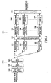
- FIG. 5 is an exemplary diagram showing a schematic structure of a receiving device according to another embodiment of the present invention. The following explanation will be given with reference to this diagram.
- the receiving device 101 comprises a receiving unit 102, a component analyzing unit 103, despreading units 104, a selective output unit 105, and modulation units 106, which are configured as follows.
- the receiving unit 102 receives a signal directly spread by a chaos code, which is transmitted from a transmitting device.
- the signal received by the receiving unit 102 is generally a signal transmitted wirelessly, to which components of not only the transmitting device which the receiving device 101 requests to have communication with, but also components (of any other transmitting device, noises of various kinds, influences of reflection, delay, and interference in the radio wave transmission paths, etc.) that are emitted from any other radio wave emission source are added.
- the transmitting device In a case where the transmitting device is to transmit a signal by using a chaos code, it typically encodes the signal to be transmitted, multiplies the resultant signal by a chaos code common to the receiving device 101, modulates the carrier wave, and then wirelessly transmits the signal from an antenna.
- the component analyzing unit 103 performs component analysis of the received signal, and separates it into a plurality of components. As described above, independent component analysis is used in the present embodiment. The process of the component analyzing unit 103 will be specifically explained below.
- the received signal is the result of multiplication of a signal as shown at the lowermost-left diagram of FIG. 3 by a multiplier corresponding to the condition of the transmission path, and subsequent addition. At this time, if there have been a plurality of transmission paths, the signal has received influences of delays and influences of noises in the transmission paths.
- any of principal component analysis including component analysis by sphering), independent component analysis, and component analysis by non-negative matrix factorization (NMF) outputs M (1 ⁇ M) number of vectors having the same length as the result of component analysis, when given M number of vectors having a uniform length as inputs.
- any of the vectors having large sizes among the vectors obtained as the result of component analysis is the signal that is intended to be transmitted to the receiving device 101, and the rest of the vectors are signals intended to be transmitted to other receiving devices or noises.
- Received through the antenna is only one signal. That is, there exists only one vector having an infinite length.
- the received signal is a signal having been embedded on a carrier wave and such a signal is to be digitally processed. Therefore, it is desired that the time unit e in which each component of the vector of the received signal is sequentially extracted (this time unit corresponding to the sampling frequency of the received signal) be shorter than the chip length d of the spreading code ad shorter than a frequency 1/f calculated from the carrier frequency f of the carrier wave.
- the number C may be any integer multiple (2 ⁇ T ⁇ f, 3 ⁇ T ⁇ f, ...) of this.
- FIG. 6 is an explanatory diagram conceptually showing how the process by the component analyzing unit 103 is. The following explanation will be given with reference to this diagram.
- the component analyzing unit 103 executes the process each time the components of the vector of the received signal are accumulated to a number MC. That is, the component analyzing unit 103 groups r 0 , r 1 , r 2 , ..., r MC-1 as the unit of the subsequent process, starts counting from 0 again when the process is carried out to the end, and repeats the same process for a new set of r 0 , r 1 , r 2 , ... , r MC-1 .
- the component analyzing unit 103 separates r 0 , r 1 , r 2 , ... , r MC-1 into M number of vectors x 0 , ... , x M-1 which have the length C, as follows.
- x 0 (r 0 , ..., r c-1 )
- x 1 (r c , ..., r 2c-1 )
- ..., x M-1 (r (M-1)C, ..., r MC-1 )
- x i (t) a notation like x i (t) will be used to express a component of a vector.
- x i t r ic + t 0 ⁇ i ⁇ M , 0 ⁇ t ⁇ C is established.
- ⁇ (t) a notation " ⁇ (t)" will be used to represent that "it is the t-th component counted from the origin being zero".
- Patent Literature 1 Various techniques disclosed in [Patent Literature 1], [Patent Literature 3], [Non-Patent Literature 1], [Non-Patent Literature 2], etc. can be used as a specific method for independent component analysis or the like.
- Various techniques such as a method of obtaining W k, i after obtaining y 0 , ..., y M-1 , a method of directly calculating the matrix W k , i , etc. are proposed, and these methods can arbitrarily be used.
- t/C is an integer division, and any remainder should be discarded.
- the range of the subscript k of z is 0, ..., M-1.
- N which is equal to or smaller than M, may be used and the range of k may be 0, ..., N-1.
- C may be any of Tf, 2Tf, 3Tf, .... Therefore, C can be arbitrarily selected according to the number N, into which the signal should be separated.
- the process to follow thereafter is the same as ordinary chaos CDMA communications.
- the demodulation units 106 demodulate the respective separated signals from the carrier waves, and the despreading units 104 despread the respective demodulated signals by the chaos code c0 assigned to the receiving device 101 concerned. As a result, a plurality of signals are obtained.
- the selective output unit 105 selects a signal having a high intensity from the plurality of despread signals, and decodes the selected signal, thereby obtaining the signal that is intended to be transmitted.
- the transmitting side might sometimes "transmit a bare signal", as one way of modulation on a carrier wave.
- the demodulation units 106 can be omitted.
- the demodulation unit 106 may be arranged at an earlier stage than the component analyzing unit 103. In this case, only one demodulation unit 106 is required.
- CDM Code Division Multiplex
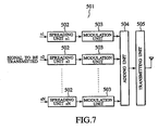
- FIG. 7 is an exemplary diagram showing a schematic structure of a transmitting device according to the present embodiment. The following explanation will be given with reference to this diagram.
- spreading units 502 to which different chaos codes c1, ..., cN are assigned, spread N number of information signals sl, ..., sN respectively, modulation units 503 modulate the respective signals on carrier waves, an adding unit 504 adds them, and a transmitting unit 505 transmits the signal from one antenna.
- the chaos codes c1, ..., cN have the same length (the same time length, too).
- the spreading results of the spreading units 502 may be added together by the adding unit 504 before carrier wave modulation is done by one modulation unit 503, in order that that a signal is transmitted from one antenna.
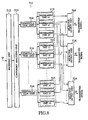
- FIG. 8 is an exemplary diagram showing a schematic structure of a receiving device according to the present embodiment. The following explanation will be given with reference to this diagram.
- a receiving unit 512 receives a transmitted signal by one antenna, and a component analyzing unit 513 separates it into a plurality of signals.
- Separated signals are demodulated from the carrier waves by demodulation units 514 respectively. Thereby, an N number of signals are obtained. An N umber of despreading units 515 despread these signals respectively.
- the set of spreading codes assigned to the N number of despreading units 515 is the same as the set of spreading codes c1, ..., cN assigned to the spreading units 502 of the transmitting device 501.
- selective output units 516 associated in one-to-one correspondence with c1, ..., cN each receive the full outputs from the spreading unit 502 to which the same spreading code is assigned, and select and output one among them that has the highest signal intensity.
- the component analyzing unit 103 repeats the process at each MC number of input signals as the unit.
- the unit of repetition may be the number C. That is, at 0-th repetition, z 0 , ..., z MC-1 are obtained from received signals r 0 , ..., r MC-1 (initialization), at 1st repetition, z MC , ... , z (M+1)C-1 are obtained from received signals r c , ... , r (M+1)C-1 , at 2nd repetition, z (M+1)C ,..., z (M+2)C-1 are obtained from received signals r 2C , ...
- r (M+2)C-1 at 3rd repetition, z (M+2)MC , ... , z (M+3)C-1 are obtained from received signals r 3C, ..., r (M+3)C-1 , ... at n-th repetition, z (M+n-1)MC, ...., z (M+n)C-1 are obtained from received signals r nC , ... , r (M+n)c-1 .
- This unit of repetition C may also be any integer multiple of C (where the multiplier is equal to or smaller than M).
- the degeneration of the separation performance can be suppressed to the lowest level possible.
- signals received by a plurality of receiving antennas can be separated into a larger number of components than the number of the receiving antennas, by the signals being folded back as in the above-described embodiment.
- the present invention can be applied even under MIMO (Multi Input Multi Output) environment as in the [example 1] and in the present example, and the present embodiment is also included in the scope of the present invention.
- MIMO Multi Input Multi Output
- the present invention it is possible to provide a receiving device and receiving method suitable for improving the communication performances by performing signal separation in CDMA communications using a chaos code, and a program for realizing these on a computer or on a digital signal processor.
Landscapes
- Engineering & Computer Science (AREA)
- Computer Networks & Wireless Communication (AREA)
- Signal Processing (AREA)
- Radio Transmission System (AREA)
- Mobile Radio Communication Systems (AREA)
Applications Claiming Priority (1)
| Application Number | Priority Date | Filing Date | Title |
|---|---|---|---|
| JP2006059098A JP2007243277A (ja) | 2006-03-06 | 2006-03-06 | 受信装置、受信方法、ならびに、プログラム |
Publications (2)
| Publication Number | Publication Date |
|---|---|
| EP1833174A2 true EP1833174A2 (de) | 2007-09-12 |
| EP1833174A3 EP1833174A3 (de) | 2007-12-19 |
Family
ID=38138421
Family Applications (1)
| Application Number | Title | Priority Date | Filing Date |
|---|---|---|---|
| EP20070004586 Withdrawn EP1833174A3 (de) | 2006-03-06 | 2007-03-06 | Empfangsvorrichtung, -verfahren und -programm |
Country Status (3)
| Country | Link |
|---|---|
| US (1) | US20070253464A1 (de) |
| EP (1) | EP1833174A3 (de) |
| JP (1) | JP2007243277A (de) |
Cited By (1)
| Publication number | Priority date | Publication date | Assignee | Title |
|---|---|---|---|---|
| CN111600672A (zh) * | 2020-05-11 | 2020-08-28 | 中国科学院国家天文台 | 生成扩频码的方法、装置、电子设备和非瞬时性计算机存储介质 |
Families Citing this family (25)
| Publication number | Priority date | Publication date | Assignee | Title |
|---|---|---|---|---|
| JP4963050B2 (ja) * | 2006-09-15 | 2012-06-27 | 独立行政法人情報通信研究機構 | 乱数列群生成装置、乱数列群生成方法、ならびに、プログラム |
| US8611530B2 (en) | 2007-05-22 | 2013-12-17 | Harris Corporation | Encryption via induced unweighted errors |
| US8363830B2 (en) | 2008-02-07 | 2013-01-29 | Harris Corporation | Cryptographic system configured to perform a mixed radix conversion with a priori defined statistical artifacts |
| US8320557B2 (en) | 2008-05-08 | 2012-11-27 | Harris Corporation | Cryptographic system including a mixed radix number generator with chosen statistical artifacts |
| US8325702B2 (en) | 2008-08-29 | 2012-12-04 | Harris Corporation | Multi-tier ad-hoc network in which at least two types of non-interfering waveforms are communicated during a timeslot |
| US8165065B2 (en) * | 2008-10-09 | 2012-04-24 | Harris Corporation | Ad-hoc network acquisition using chaotic sequence spread waveform |
| US8351484B2 (en) | 2008-12-29 | 2013-01-08 | Harris Corporation | Communications system employing chaotic spreading codes with static offsets |
| US8406276B2 (en) | 2008-12-29 | 2013-03-26 | Harris Corporation | Communications system employing orthogonal chaotic spreading codes |
| US8457077B2 (en) | 2009-03-03 | 2013-06-04 | Harris Corporation | Communications system employing orthogonal chaotic spreading codes |
| US8509284B2 (en) | 2009-06-08 | 2013-08-13 | Harris Corporation | Symbol duration dithering for secured chaotic communications |
| US8428102B2 (en) * | 2009-06-08 | 2013-04-23 | Harris Corporation | Continuous time chaos dithering |
| US8428103B2 (en) | 2009-06-10 | 2013-04-23 | Harris Corporation | Discrete time chaos dithering |
| US8379689B2 (en) | 2009-07-01 | 2013-02-19 | Harris Corporation | Anti-jam communications having selectively variable peak-to-average power ratio including a chaotic constant amplitude zero autocorrelation waveform |
| US8428104B2 (en) * | 2009-07-01 | 2013-04-23 | Harris Corporation | Permission-based multiple access communications systems |
| US8369376B2 (en) | 2009-07-01 | 2013-02-05 | Harris Corporation | Bit error rate reduction in chaotic communications |
| US8385385B2 (en) | 2009-07-01 | 2013-02-26 | Harris Corporation | Permission-based secure multiple access communication systems |
| US8363700B2 (en) * | 2009-07-01 | 2013-01-29 | Harris Corporation | Rake receiver for spread spectrum chaotic communications systems |
| US8406352B2 (en) | 2009-07-01 | 2013-03-26 | Harris Corporation | Symbol estimation for chaotic spread spectrum signal |
| US8340295B2 (en) | 2009-07-01 | 2012-12-25 | Harris Corporation | High-speed cryptographic system using chaotic sequences |
| US8369377B2 (en) | 2009-07-22 | 2013-02-05 | Harris Corporation | Adaptive link communications using adaptive chaotic spread waveform |
| US8848909B2 (en) | 2009-07-22 | 2014-09-30 | Harris Corporation | Permission-based TDMA chaotic communication systems |
| US8345725B2 (en) * | 2010-03-11 | 2013-01-01 | Harris Corporation | Hidden Markov Model detection for spread spectrum waveforms |
| US8942659B2 (en) * | 2011-09-08 | 2015-01-27 | Drexel University | Method for selecting state of a reconfigurable antenna in a communication system via machine learning |
| US9479217B1 (en) * | 2015-07-28 | 2016-10-25 | John David Terry | Method and apparatus for communicating data in a digital chaos cooperative network |
| KR102381437B1 (ko) * | 2017-06-27 | 2022-03-31 | 삼성전자주식회사 | 무선 통신 시스템에서 신호를 디코딩하기 위한 장치 및 방법 |
Family Cites Families (8)
| Publication number | Priority date | Publication date | Assignee | Title |
|---|---|---|---|---|
| JP4210717B2 (ja) * | 2001-03-26 | 2009-01-21 | 独立行政法人科学技術振興機構 | 送信装置、受信装置、送信方法、受信方法、プログラム、ならびに、情報記録媒体 |
| US7411997B2 (en) * | 2001-03-26 | 2008-08-12 | Japan Science And Technology Corporation | Apparatus and method for filtering a spectrum spread communication |
| JP3525146B2 (ja) * | 2001-11-05 | 2004-05-10 | 独立行政法人 科学技術振興機構 | 乱数列出力装置、乱数列出力方法、プログラムならびに、情報記録媒体 |
| JP2004235860A (ja) * | 2003-01-29 | 2004-08-19 | Toshiba Corp | 受信装置 |
| WO2004112271A1 (ja) * | 2003-06-13 | 2004-12-23 | Japan Science And Technology Agency | 通信装置および通信方法 |
| JP2005051344A (ja) * | 2003-07-30 | 2005-02-24 | Toshiba Corp | 通信システム |
| US7116271B2 (en) * | 2004-09-23 | 2006-10-03 | Interdigital Technology Corporation | Blind signal separation using spreading codes |
| JP4836559B2 (ja) * | 2005-11-28 | 2011-12-14 | 独立行政法人情報通信研究機構 | 受信方法および受信装置 |
-
2006
- 2006-03-06 JP JP2006059098A patent/JP2007243277A/ja active Pending
-
2007
- 2007-03-06 EP EP20070004586 patent/EP1833174A3/de not_active Withdrawn
- 2007-03-06 US US11/714,446 patent/US20070253464A1/en not_active Abandoned
Non-Patent Citations (2)
| Title |
|---|
| RISTANIEMI: "Learning Algorithms for Blind Symbol Separation in CDMA Downlink", IN PROCEEDINGS OF PIMRC' 98, September 1998 (1998-09-01), Retrieved from the Internet <URL:www.jyu.fi/jyrkij/pimrc98.ps> |
| Y. SOOBUL; K. CHADY; H.C.S. RUGHOOPUTH: "Digital Chaotic Coding and Modulation in CDMA", 6TH AFRICON, vol. 2, October 2002 (2002-10-01), pages 841 - 846 |
Cited By (1)
| Publication number | Priority date | Publication date | Assignee | Title |
|---|---|---|---|---|
| CN111600672A (zh) * | 2020-05-11 | 2020-08-28 | 中国科学院国家天文台 | 生成扩频码的方法、装置、电子设备和非瞬时性计算机存储介质 |
Also Published As
| Publication number | Publication date |
|---|---|
| JP2007243277A (ja) | 2007-09-20 |
| US20070253464A1 (en) | 2007-11-01 |
| EP1833174A3 (de) | 2007-12-19 |
Similar Documents
| Publication | Publication Date | Title |
|---|---|---|
| US20070253464A1 (en) | Receiving device, receiving method, and program | |
| JP3778969B2 (ja) | スペクトラム拡散コードパルス位置変調のための方法及び装置 | |
| US7697590B2 (en) | Communicating apparatus and communicating method | |
| US8477827B2 (en) | Spread-spectrum coding of data bursts | |
| US7511637B2 (en) | Spreading code derived from weil sequences | |
| US20190268035A1 (en) | Reliable orthogonal spreading codes in wireless communication | |
| US20180254929A1 (en) | Method and device for transmitting pay load sequence | |
| WO2002078183A1 (en) | Filter apparatus, reception apparatus, transmission apparatus, diffusion modulation apparatus, pseudo-random number sequence output apparatus, filter method, reception method, transmission method, diffusion modulation method, pseudo-random number sequence output method, and program | |
| JPH06500441A (ja) | 逆モードsaw相関方法及び装置 | |
| US20210006390A1 (en) | Method for Generating Digital Quantum Chaotic Wavepacket Signals | |
| CN112929904B (zh) | 一种信息的传输方法、装置、通信设备及存储介质 | |
| US20060198522A1 (en) | Wide band-DCSK modulation method, transmitting apparatus thereof, wide band-DCSK demodulation method, and receiving apparatus thereof | |
| US20040213330A1 (en) | Apparatus and method for transmitting signal based on interleaving delay diversity | |
| US8942318B1 (en) | Method and apparatus of cross-correlation | |
| US20030112849A1 (en) | Efficient quadrature code position modulation | |
| JP5131550B2 (ja) | 拡散符号計算装置、通信システム、送信装置、受信装置、ならびに、プログラム | |
| CN112788631B (zh) | 一种信息的传输方法、装置、通信设备及存储介质 | |
| KR100643745B1 (ko) | 한점 직교 및 zcd 구간을 갖는 단극성 코드를 이용하는ook-cdma 기반의 유무선 통신 시스템 및 그 방법 | |
| US20060171447A1 (en) | Method for interwoven spreading codes | |
| US20190052305A1 (en) | Two-phase transmission for machine-type communication | |
| KR102895225B1 (ko) | Sfh-dm 기반의 주파수 호핑 방법 및 장치 | |
| CN115792810A (zh) | 用于并发雷达操作的雷达系统、雷达布置和雷达方法 | |
| JP4836559B2 (ja) | 受信方法および受信装置 | |
| KR101269849B1 (ko) | 통신 시스템의 채널 확산을 위한 수열 족의 생성 장치 및 방법 | |
| CN101133583B (zh) | 用于交织扩展码的方法 |
Legal Events
| Date | Code | Title | Description |
|---|---|---|---|
| PUAI | Public reference made under article 153(3) epc to a published international application that has entered the european phase |
Free format text: ORIGINAL CODE: 0009012 |
|
| 17P | Request for examination filed |
Effective date: 20070306 |
|
| AK | Designated contracting states |
Kind code of ref document: A2 Designated state(s): AT BE BG CH CY CZ DE DK EE ES FI FR GB GR HU IE IS IT LI LT LU LV MC MT NL PL PT RO SE SI SK TR |
|
| AX | Request for extension of the european patent |
Extension state: AL BA HR MK YU |
|
| PUAL | Search report despatched |
Free format text: ORIGINAL CODE: 0009013 |
|
| AK | Designated contracting states |
Kind code of ref document: A3 Designated state(s): AT BE BG CH CY CZ DE DK EE ES FI FR GB GR HU IE IS IT LI LT LU LV MC MT NL PL PT RO SE SI SK TR |
|
| AX | Request for extension of the european patent |
Extension state: AL BA HR MK YU |
|
| 17Q | First examination report despatched |
Effective date: 20080703 |
|
| AKX | Designation fees paid |
Designated state(s): AT BE BG CH CY CZ DE DK EE ES FI FR GB GR HU IE IS IT LI LT LU LV MC MT NL PL PT RO SE SI SK TR |
|
| STAA | Information on the status of an ep patent application or granted ep patent |
Free format text: STATUS: THE APPLICATION IS DEEMED TO BE WITHDRAWN |
|
| 18D | Application deemed to be withdrawn |
Effective date: 20101001 |