EP1832871B1 - Wechselarmatur für einen Sensor - Google Patents
Wechselarmatur für einen Sensor Download PDFInfo
- Publication number
- EP1832871B1 EP1832871B1 EP07103605A EP07103605A EP1832871B1 EP 1832871 B1 EP1832871 B1 EP 1832871B1 EP 07103605 A EP07103605 A EP 07103605A EP 07103605 A EP07103605 A EP 07103605A EP 1832871 B1 EP1832871 B1 EP 1832871B1
- Authority
- EP
- European Patent Office
- Prior art keywords
- sensor
- sealing
- housing
- assembly
- retractable
- Prior art date
- Legal status (The legal status is an assumption and is not a legal conclusion. Google has not performed a legal analysis and makes no representation as to the accuracy of the status listed.)
- Not-in-force
Links
Images
Classifications
-
- G—PHYSICS
- G01—MEASURING; TESTING
- G01N—INVESTIGATING OR ANALYSING MATERIALS BY DETERMINING THEIR CHEMICAL OR PHYSICAL PROPERTIES
- G01N27/00—Investigating or analysing materials by the use of electric, electrochemical, or magnetic means
- G01N27/26—Investigating or analysing materials by the use of electric, electrochemical, or magnetic means by investigating electrochemical variables; by using electrolysis or electrophoresis
- G01N27/28—Electrolytic cell components
- G01N27/283—Means for supporting or introducing electrochemical probes
-
- G—PHYSICS
- G01—MEASURING; TESTING
- G01D—MEASURING NOT SPECIALLY ADAPTED FOR A SPECIFIC VARIABLE; ARRANGEMENTS FOR MEASURING TWO OR MORE VARIABLES NOT COVERED IN A SINGLE OTHER SUBCLASS; TARIFF METERING APPARATUS; MEASURING OR TESTING NOT OTHERWISE PROVIDED FOR
- G01D11/00—Component parts of measuring arrangements not specially adapted for a specific variable
- G01D11/30—Supports specially adapted for an instrument; Supports specially adapted for a set of instruments
Definitions
- the invention relates to an interchangeable fitting with a fitting housing and with a linearly guided in the fitting housing between a first position and a second position tubular support for a sensor, wherein the sensor determines a physical and / or chemical process variable in a process.
- Retractable fittings are widely used in analytical instrumentation. They are used to remove sensors from the process without process interruption, even at process pressures of up to 10 bar and more, and then re-introduce them into the process. For this purpose, the sensor is moved automatically or manually from a measuring position to a maintenance or service position and back. In the maintenance position, the sensor is checked, calibrated or simply cleaned, which, depending on the application, is very important for the quality of the measurements.
- a ball valve or a plug valve is used, the opening through which the sensor is moved in and out of the process via a rotating roller to the Process opens or closes.
- a locking pin is used. This plug is an integral part of the retractable fitting.
- Ball valve fittings are preferably used in media with solids content.
- solids are meant fibers, but also adherent caking of lime and similar substances.
- the sensor is moved out of the process and into the process in ball valve fittings, separate from the closing / opening mechanism. For this purpose, the ball valve is closed or opened. To clean the sensor, the sensor is placed in the maintenance position in a rinsing chamber separated from the process.
- Retractable fittings are different from the applicant Events under the name 'CleanFit' offered and distributed. Fittings with locking pins are, for example, under the designations CleanFit S, CPA 471, CPA 472, CPA 473 and CPA 474. out.
- the holder for the sensor itself is designed as a sealing element.
- the front part of the holder is designed as a pin, which seals radially during the return to the process connection.
- the construction of the sealing system of the fittings CPA 471 and CPA 472 ensures a perfect separation between the rinsing chamber and thus the "outside world", and the process - in each position of the holder.
- the two O-rings that are important for the sealing function are located on the outside of the holder of the sensor and are therefore relatively easy to check and, if necessary, replace. For this, the valve must be removed from the process adaptation during a process break.
- a transmitter device is described with a guide device which is fastened to a connection piece of a container and is provided with a shut-off device.
- a probe is displaceably mounted between an operating position and an insertion position.
- the probe is guided in the guide means by a guide bushing on the probe, which slides on the probe and which is inserted into the cylindrical guide means at its process-remote end and held by a locking member in the guide means.
- the probe has a transmitter and is equipped in this area with an external seal, which cooperates in the operating position of the probe with the guide channel of the connection piece, to ensure that no medium from the container in the rear part of the Transmitter device arrives.
- Sterilization medium for sterilizing the probe retracted into the guide device can be introduced into the inner cylinder of the guide device in this position.
- the located in the inner cylinder part of the probe is sealed by sealing rings in the guide bush to the rear.
- the valve In addition to these outer O-rings, the valve also has internal O-rings in the area of the holder's guide. Due to their internal installation, these O-rings are well protected against external influences such as abrasive media. However, it is not easy to replace the O-rings usually located inside the flushing chamber.
- the O-rings are arranged in the washing chamber in the region of the passage for the holder.
- a probe device for recording, positioning, calibration and / or maintenance of a measuring electrode which includes a submerged in the medium probe housing, a holder for the Measuring electrode, which is displaceable between a measuring and a calibration position, and a calibration chamber in which the measuring electrode is positionally sealed in a calibration position against the medium to be measured has.
- the holder is guided axially displaceably in a bush, which has no sealing function.
- the sealing of the calibration chamber with respect to a process fluid takes place by means of a rotary slide device with a fixed sealing part and a rotating part rotatable on the contrary, which are sealed by mutually fitting, planar sealing surfaces.
- a further problem with the hitherto known solutions is that the sealing concept with two inner O-rings in the fitting housing can lead to total failures of the retractable fitting if, in one method, the tubular support is scratched from one position to the other by friction at the contact surfaces. and cratering occurs. Corresponding damage makes replacement of the retractable fitting absolutely necessary.
- the CPA 475 faucet has a comparable sealing system.
- This fitting which is designed for use in sterile applications in the food and pharmaceutical industries, uses a molded seal.
- the holder for the sensor is formed so that the locking pin in the service position and the holder in the measuring position together with the molded seal to ensure the tightness.
- the holder in the washing chamber is free cleanable and sterilizable.
- the molded gasket is of crucial importance in that the retractable fitting can be used in processes with high hygienic requirements.
- the molded seal is formed so that no undercuts can occur as in O-rings, which in turn serve as a reservoir for bacteria and contaminants due to the poor accessibility of the undercut areas.
- the invention has for its object to propose a retractable housing, which allows easy disassembly / assembly of a sealing ring.
- a sealing bush is provided which on the surface of the tubular support facing at least one circumferential groove having a sealing ring, wherein the sealing bushing is positioned in the fitting housing, so that it leads the holder parallel to its longitudinal axis between the first position and the second position.
- An advantage of the retractable assembly according to the invention is the fact that the outside of the sealing bush defective seals can be easily replaced by new seals. Since the sealing rings can be easily replaced, they can be flexibly adapted to any application. Also, the sealing bush is completely replaced in the event of a fault, which reduces the downtime of the retractable fitting in case of failure. By replacing each optimal sealing function of the retractable housing is guaranteed. In general, it can be said that the retractable assembly according to the invention is characterized by an increased efficiency and a great service friendliness. This increases the acceptance and satisfaction of the customers.
- a first groove, a second groove and a third groove are provided on the surface in the direction of movement of the holder, wherein in each groove a respective sealing ring is positioned.
- the two outer sealing rings are scraper rings, while the middle ring is preferably an O-ring.
- the sealing bush is made of a plastic material and the retractable fitting is made of metal.
- the sealing bushing uses a high-quality plastic, PEEK.
- PEEK has a high temperature resistance and is very resistant to aggressive chemical process media.
- PEEK stands out for its outstanding dimensional stability, which of course is very important for the guiding and bearing function of the sealing bushing.
- the valve body and the pipeline are however made of stainless steel.
- the sealing bush is designed as a module which can be fastened by means of a fastening in the fitting housing. If the sealing bush is designed as an exchangeable module, the replacement of defective seals is greatly facilitated. It is also possible to optimally match the modules with regard to the choice of material to the respective application.
- the attachment is preferably via screws.
- the sealing bush is an integral part of the valve body.
- the part in which the seals are arranged can also be subsequently rotated out of a conventional retractable fitting in order to install the inventive sealing bushing.
- the valve housing comprises a rinsing chamber for the sensor acts.
- the senor is in the first position in the rinsing chamber and is here cleaned or calibrated or, if necessary, doused. In the second position, the sensor provides measurement data about the physical and / or chemical process variable.
- the sensor can be any sensor that requires periodic cleaning and / or recalibration. It is preferably a potentiometric sensor, for example a pH electrode, a redox electrode or a Oxygen sensor, or around a temperature sensor.
- a potentiometric sensor for example a pH electrode, a redox electrode or a Oxygen sensor, or around a temperature sensor.
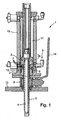
- Fig. 1 a longitudinal section through a preferred embodiment of the retractable fitting according to the invention
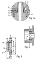
- Fig. 1a the in Fig. 1 A section marked A, which shows the shape of the sealing bush and its arrangement of the sealing bush in the flushing chamber.
- Fig. 2 a section through the valve body with installation space for the sealing bush
- Fig. 3 the sealing bush in side view.
- Fig. 1 shows a longitudinal section through a preferred embodiment of the retractable assembly according to the invention 1.
- Fig. 1a is the in Fig. 1 A section marked A, which shows the shape of the sealing bush 6 and its arrangement in the rinsing chamber 5.
- the retractable fitting 1 is the process retractable fitting 1 Cleanfit CPA473 offered and distributed by the Applicant - in the case shown with manual actuation of the ball valve 8.
- the senor 4 which can be moved in the tubular holder 3 in the axial direction, is in the measuring position and provides measurement data on the respectively measured or monitored process variable.
- the sensor 4 - here a pH glass electrode - moved to the service or maintenance position.
- the ball valve 8 is closed via the adjusting mechanism 14, whereby the interior of the fitting housing 2 is sealed against the process.
- the interior of the fitting housing 2 to the washing chamber 5 is in contact with the process for a short time.
- An intrusion of process medium in the drive chamber 17 located behind the washing chamber 5 is inventively through the sealing bushing. 6 prevented.
- the preferably designed as a module sealing bush 6 ( Fig. 3 ) consists of a substantially cylindrical part, wherein the one end region of the thickness b has a larger diameter D than the other end region of the thickness B with the diameter d.
- axially parallel holes 11 are provided in the end region of the thickness b .
- the sealing bushing 6 can be fastened to the washing chamber 5.
- the sealing rings 7a, 7b, 7c can also have different shapes, since the grooves 12a, 12b, 12c in the sealing bushing 6 can be modified in a simple manner without the rinsing chamber 5, which is complex in terms of production, having to be modified as such.
- the sealing bushing 6 is made of a different material than the rinsing chamber 5. If the sealing bushing 6 is made of plastic, then the probability can be minimized that the retractable assembly 1 becomes permanently leaky due to the formation of grooves or craters on the contact surfaces of the components moving relative to one another.
- the sealing bushing 6 serves to support and guide the tubular support 3 and, as already stated, seals the flushing chamber 5 against the process when the ball valve 8 is opened.
- On the outer surface of the sealing bush 6 are - as in Fig. 3 see - three circumferential grooves 12a, 12b, 12c provided, in which the sealing rings 7a, 7b, 7c are placed.
- the two outer sealing rings 7a, 7c are preferably wiper rings, which strip particles of the process medium located on the holder 3 from one position to the other position during the method of the sensor 4.
- the middle sealing ring 7b is an O-ring.
- the outer sealing rings 7 are two Turcon Varisealringe.
- the sealing bushing 6 is used as a sealing package in the corresponding for installation in the rinsing chamber 5 provided installation space 16 is inserted and fixed there. Good to see the tuned to the size of the sealing bushing 6 installation space 16 in Fig. 2 ,
Landscapes
- Chemical & Material Sciences (AREA)
- General Physics & Mathematics (AREA)
- Health & Medical Sciences (AREA)
- Life Sciences & Earth Sciences (AREA)
- Physics & Mathematics (AREA)
- Analytical Chemistry (AREA)
- Pathology (AREA)
- Electrochemistry (AREA)
- Molecular Biology (AREA)
- Biochemistry (AREA)
- General Health & Medical Sciences (AREA)
- Immunology (AREA)
- Chemical Kinetics & Catalysis (AREA)
- Details Of Valves (AREA)
- Push-Button Switches (AREA)
- Mechanisms For Operating Contacts (AREA)
- Lock And Its Accessories (AREA)
- Indication Of The Valve Opening Or Closing Status (AREA)
- Measuring Fluid Pressure (AREA)
Description
- Die Erfindung betrifft eine Wechselarmatur mit einem Armaturengehäuse und mit einer in dem Armaturengehäuse linear zwischen einer ersten Position und einer zweiten Position geführten rohrförmigen Halterung für einen Sensor, wobei der Sensor eine physikalische und/oder chemische Prozessgröße in einem Prozess bestimmt.
- Wechselarmaturen sind in der Analysemesstechnik weit verbreitet. Sie dienen dazu, Sensoren ohne Prozessunterbrechung selbst bei Prozessdrücken bis zu 10 bar und mehr aus dem Prozess zu entnehmen und anschließend wieder in den Prozess einzuführen. Der Sensor wird hierzu automatisch oder manuell von einer Messposition in eine Wartungs- oder Serviceposition und zurück verfahren. In der Wartungsposition wird der der Sensor überprüft, kalibriert oder aber einfach nur gereinigt, was je nach Anwendungsfall für die Güte der Messungen von großer Bedeutung ist.
- Als Prozessabschluss zum Medium sind zwei unterschiedliche Lösungen im zum Einsatz: Bei einer ersten Ausführungsform wird ein Kugelhahn bzw. ein Kükenhahn verwendet, der über eine rotierende Walze die Öffnung, durch die der Sensor in den Prozess hinein- und aus dem Prozess herausbewegt wird, zum Prozess hin öffnet oder schließt. Bei einer zweiten Ausführungsform kommt ein Verschlusszapfen zum Einsatz. Dieser Verschlusszapfen ist integraler Bestandteil der Wechselarmatur ist.
- Kugelhahnarmaturen werden bevorzugt in Medien mit Feststoffanteil einge-setzt. Unter Feststoffen werden Fasern, aber auch festhaftende Anbackungen von Kalk und ähnlichen Stoffen verstanden. Der Sensor wird in Kugelhahn-armaturen getrennt vom Schließ-/Öffnungsmechanismus aus dem Prozess heraus- und in den Prozess hineingefahren. Hierzu wird der Kugelhahn geschlossen bzw. geöffnet. Zwecks Reinigung des Sensors wird der Sensor in der Wartungsposition in eine vom Prozess abgetrennte Spülkammer eingebracht.
- Wechselarmaturen werden von der Anmelderin in unterschiedlichen Ausge-staltungen unter der Bezeichnung 'CleanFit' angeboten und vertrieben. Armaturen mit Verschlußzapfen werden beispielsweise unter den Bezeich-nungen CleanFit S, CPA 471, CPA 472, CPA 473 und CPA 474. geführt. Bei diesen Wechselarmaturen ist die Halterung für den Sensor selbst als Dichtelement ausgestaltet. Der vordere Teil der Halterung ist als Zapfen ausgebildet, der bereits während des Zurückfahrens zum Prozessanschluss hin radial abdichtet. Der Aufbau des Dichtungssystems der Armaturen CPA 471 und CPA 472 gewährleistet dabei eine perfekte Trennung zwischen der Spülkammer und damit der "Außenwelt", und dem Prozess - und zwar in jeder Stellung der Halterung.
- Es versteht sich von selbst, dass diese Trennung nur wirksam ist, wenn die Dichtringe nicht beschädigt sind. Eine konsequente Kontrolle der Dichtringe ist daher unbedingt zu empfehlen. Allerdings bedeutet Kontrolle bei vielen Armaturen eine Demontage der kompletten Wechselarmatur. Darüber hinaus darf eine Kontrolle bzw. ein Austausch der Dichtringe nur durch geschultes Personal durchgeführt werden, da die Armatur anschließend wieder korrekt unter den herrschenden Prozessbedingungen arbeiten muss.
- Im Falle der CPA 471 und CPA 472 liegen die beiden für die Dichtfunktion wichtigen O-Ringe außen an der Halterung des Sensors und sind so relativ einfach zu kontrollieren und gegebenenfalls zu ersetzen. Hierzu muss die Armatur während einer Prozesspause aus der Prozessadaption genommen werden.
- In
DE 33 25 309 A1 ist eine Messwertgebereinrichtung mit einer Führungseinrichtung beschrieben, die an einem Anschlussstutzen eines Behälters befestigbar ist und mit einem Absperrorgan versehen ist. In der Führungseinrichtung ist eine Sonde zwischen einer Betriebsstellung und einer Einsetzstellung verschieblich gelagert. Die Sonde wird in der Führungseinrichtung durch eine Führungsbuchse an der Sonde geführt, die auf der Sonde gleitet und die in die zylindrische Führungseinrichtung an ihrem prozessabgewandten Ende eingesteckt und mittels eines Arretiergliedes in der Führungseinrichtung gehalten wird. An ihrem vorderen Ende weist die Sonde einen Messwertgeber auf und ist in diesem Bereich mit einer außen liegenden Dichtung ausgestattet, die in Betriebsstellung der Sonde mit dem Führungskanal des Anschlussstutzens zusammenwirkt, um dafür zu sorgen, dass kein Medium aus dem Behälter in den rückwärtigen Teil der Messwertgebereinrichtung gelangt. In der Einsetzstellung ist das Absperrorgan geschlossen und verhindert so das Eindringen von Medium aus dem Behälter in die Messwertgebereinrichtung. In den Innenzylinder der Führungseinrichtung kann in dieser Stellung Sterilisationsmedium zur Sterilisierung der in die Führungseinrichtung zurückgezogenen Sonde eingeleitet werden. Der in dem Innenzylinder liegende Teil der Sonde ist durch Dichtungsringe in der Führungsbuchse nach rückwärts abgedichtet. - Neben diesen außen liegenden O-Ringen besitzt die Armatur zusätzlich im Bereich der Führung der Halterung auch innen liegende O-Ringe. Durch den Inneneinbau sind diese O-Ringe vor äußeren Einflüssen wie abrasiven Medien gut geschützt. Es ist jedoch nicht ganz einfach, die üblicherweise innen in der Spülkammer liegenden O-Ringe auszutauschen. Die O-Ringe sind in der Spülkammer im Bereich der Durchführung für die Halterung angeordnet.
- In
EP 1 156 323 A1 ist eine Sondeneinrichtung zur Aufnahme, Positionierung, Kalibrierung und/oder Wartung einer Messelektrode beschrieben, die ein in das Medium eintauchbares Sondengehäuse, eine Halterung für die Messelektrode, die zwischen einer Mess- und einer Kalibrierstellung verschiebbar ist, und eine Kalibrierkammer, in der die Messelektrode in einer Kalibrierstellung gegen das zu messende Medium abgedichtet positionierbar ist, aufweist. Die Halterung ist in einer Buchse axial verschiebbar geführt, die keine Dichtfunktion besitzt. Die Abdichtung der Kalibrierkammer gegenüber einer Prozessflüssigkeit erfolgt durch eine Drehschiebereinrichtung mit einem festen Dichtteil und einem demgegenüber drehbaren Drehteil, die durch gegenseitig anliegende, plane Dichtflächen abgedichtet sind. - Ein Austausch der Dichtringe ist in gewissen Zeitabständen zwecks Sicherstellung der Dichtfunktion notwendig, da O-Ringe, die üblicherweise aus Polymeren bestehen, nach einer gewissen Standzeit an einer Oberfläche, auf die sie angepresst werden, festkleben. Wird nun die Halterung relativ zum Armaturengehäuse bewegt, so besteht die Gefahr, dass die Oberfläche des Polymers, also des O-Rings, beschädigt wird. Dieser Effekt ist unter der Bezeichnung Slipstick-Effekt bekannt. Bei Auftreten des Effekts ist die Dichtfunktion eines O-Rings nicht mehr gewährleistet.
- Problematisch ist weiterhin bei den bisher bekannten Lösungen, dass das Dichtkonzept mit zwei innen liegenden O-Ringen im Armaturengehäuse zu Total-Ausfällen der Wechselarmatur führen kann, wenn bei einem Verfahren der rohrförmigen Halterung von einer Position in die andere durch Reibung an den Kontaktflächen Riefen- und Kraterbildung auftritt. Eine entsprechende Beschädigung macht den Austausch der Wechselarmatur unbedingt notwendig.
- Ein vergleichbares Dichtungssystem besitzt die Armatur CPA 475. In dieser für den Einsatz bei sterilen Anwendungen in der Lebensmittel- und Pharmaindustrie konzipierten Armatur kommt eine Formdichtung zum Einsatz. Hier ist die Halterung für den Sensor so ausgeformt, dass der Verschlusszapfen in der Serviceposition und die Halterung in der Messposition jeweils zusammen mit der Formdichtung die Dichtigkeit gewährleisten. Damit ist die Halterung in der Spülkammer frei reinig- und sterilisierbar.
- Die Formdichtung ist von ausschlaggebender Wichtigkeit dafür, dass die Wechselarmatur in Prozessen mit hohen Hygieneanforderungen eingesetzt werden kann. Insbesondere ist die Formdichtung so ausgeformt, dass keine Hinterschnitte wie bei O-Ringen entstehen können, die wiederum aufgrund der schlechten Zugänglichkeit der hinterschnittenen Bereiche als Sammelbecken für Bakterien und Verunreinigungen dienen.
- Der Erfindung liegt die Aufgabe zugrunde, eine Wechselarmatur vorzuschlagen, die eine einfache Demontage/Montage eines Dichtrings ermöglicht.
- Die Aufgabe wird dadurch gelöst, dass eine Dichtbuchse vorgesehen ist, die auf der der rohrförmigen Halterung zugewandten Oberfläche zumindest eine umlaufende Nut mit einem Dichtring aufweist, wobei die Dichtbuchse sie in dem Armaturengehäuse positioniert ist, so dass sie die Halterung parallel zu Ihrer Längsachse zwischen der ersten Position und der zweiten Position führt.
- Ein Vorteil der erfindungsgemäßen Wechselarmatur ist darin zu sehen, dass die an der Dichtbuchse außen liegenden defekten Dichtungen auf einfache Art und Weise durch neue Dichtungen ersetzt werden können. Da sich die Dichtringe einfach austauschen lassen, können Sie flexibel an jede Applikation angepasst werden. Auch wird die Dichtbuchse im Fehlerfall komplett ausgetauscht, wodurch sich die Ausfallzeit der Wechselarmatur bei einer Störung reduziert. Durch den Austausch ist jeweils eine optimale Dichtfunktion des Wechselarmatur gewährleistet. Allgemein lässt sich sagen, dass sich die erfindungsgemäße Wechselarmatur durch eine erhöhte Leistungsfähigkeit und eine große Servicefreundlichkeit auszeichnet. Hierdurch wird die Akzeptanz und Zufriedenheit der Kunden erhöht.
- Gemäß einer Weiterbildung der erfindungsgemäßen Wechselarmatur sind an der Oberfläche in Bewegungsrichtung der Halterung eine erste Nut, eine zweite Nut und eine dritte Nut vorgesehen, wobei in jeder Nut jeweils ein Dichtring positioniert ist. Bevorzugt handelt es sich bei den beiden äußeren Dichtringen um Abstreifringe, während es sich bei dem mittleren Ring bevorzugt um einen O-Ring handelt.
- Die Dichtbuchse ist aus einem Kunststoff und die Wechselarmatur aus Metall gefertigt. Dabei kommt bei der Dichtbuchse ein hochwertiger Kunststoff, PEEK, zum Einsatz. PEEK besitzt eine hohe Temperaturbeständigkeit und ist sehr resistent gegenüber aggressiven chemischen Prozessmedien. Darüber hinaus zeichnet PEEK sich durch eine hervorragende Formbeständigkeit aus, was für die Führungs- und Lagerfunktion der Dichtbuchse natürlich sehr wichtig ist. Das Armaturengehäuse und die Rohrleitung sind hingegen aus Edelstahl gefertigt.
- Diese Kombination einer Dichtbuchse aus Kunststoff mit einem metallenen Armaturengehäuse hat den Vorteil, dass bei Verschleiß oder Beschädigung der Dichtringe die Gefahr ausgeschlossen ist, dass im Bereich der Kontaktflächen von rohrförmiger Halterung und Dichtbuchse im Durchgang der Spülkammer Riefen oder sonstige Beschädigungen der Oberflächen auftreten, was zu einer dauerhaften Undichtigkeit der Wechselarmatur führen würden.
- Gemäß einer bevorzugten Ausgestaltung der erfindungsgemäßen Wechsellarmatur ist die Dichtbuchse als Modul ausgebildet, das mittels einer Befestigung in dem Armaturengehäuse befestigbar ist. Ist die Dichtbuchse als austauschbares Modul ausgestaltet, so wird das Auswechseln defekter Dichtungen ganz erheblich erleichtert. Auch ist es möglich, die Module hinsichtlich der Materialwahl optimal auf den jeweiligen Anwendungsfall abzustimmen. Die Befestigung erfolgt bevorzugt über Schrauben.
- Alternativ wird vorgeschlagen, dass die Dichtbuchse integraler Teil des Armaturengehäuses ist. Beispielsweise kann auch nachträglich aus einer herkömmlichen Wechselarmatur das teil, in dem die Dichtungen angeordnet sind, herausgedreht werden, um die erfindundungsgemäße Dichtbuchse einzubauen.
- Das Armaturengehäuse umfasst eine Spülkammer für den Sensor handelt.
- Wie bereits an vorhergehender Stelle erwähnt, befindet sich der Sensor in der ersten Position in der Spülkammer und wird hier gereinigt oder kalibriert oder bei Bedarf ausgetasucht. In der zweiten Position stellt der Sensor Messdaten über die physikalische und/oder chemische Prozessgröße zur Verfügung.
- Bei dem Sensor kann es sich um jeden beliebigen Sensor handeln, der in gewissen Abständen gereinigt und oder nachkalibriert werden muss. Bevorzugt handelt es sich um einen potentiometrischen Sensor, beispiels-weise eine pH-Elektrode, eine Redox-Elektrode oder einen Sauerstoffsensor, oder um einen Temperatursensor.
- Die Erfindung wird anhand der nachfolgenden Zeichnungen näher erläutert. Es zeigt:
-
Fig. 1 : einen Längsschnitt durch eine bevorzugte Ausgestaltung der erfindungsgemäßen Wechselarmatur, -
Fig. 1a : den inFig. 1 mit A gekennzeichneten Ausschnitt, der die Form Dichtbuchse und ihre Anordnung der Dichtbuchse in der Spülkammer zeigt, -
Fig. 2 : einen Schnitt durch das Armaturengehäuse mit Einbauraum für die Dichtbuchse und -
Fig. 3 : die Dichtbuchse in Seitenansicht. -
Fig. 1 zeigt einen Längsschnitt durch eine bevorzugte Ausgestaltung der erfindungsgemäßen Wechselarmatur 1. InFig. 1a ist der inFig. 1 mit A gekennzeichneten Ausschnitt dargestellt, der die Form Dichtbuchse 6 und ihre Anordnung in der Spülkammer 5 zeigt. Bei der Wechselarmatur 1 handelt es sich um die von der Anmelderin angebotene und vertriebene Prozess-Wechselarmatur 1 Cleanfit CPA473 - im dargestellten Fall mit manueller Betätigung des Kugelhahns 8. - Im gezeigten Fall befindet sich der Sensor 4, der in der rohrförmigen Halterung 3 in axialer Richtung bewegt werden kann, in der Messposition und stellt Messdaten über die jeweils gemessene oder überwachte Prozessgröße zur Verfügung.
- Über einen pneumatischen Antrieb, der in der
Fig. 1 nicht in allen Details gezeigt ist, wird der Sensor 4 - hier eine pH-Glaselektrode - in die Sevice- oder Wartungsposition verfahren. Sobald der Sensor 4 die Wartungsposition erreicht hat, wird der Kugelhahn 8 über den Verstellmechanismus 14 geschlossen, wodurch der Innenraum des Armaturengehäuses 2 gegen den Prozess hin abgedichtet ist. Während des Schließvorgangs ist der Innenraum des Armaturengehäuses 2 bis zur Spülkammer 5 für kurze Zeit in Kontakt mit dem Prozess. Ein Eindringen von Prozessmedium in den hinter der Spülkammer 5 befindlichen Antriebsraum 17 wird erfindungsgemäß durch die Dichtbuchse 6 verhindert. - Die bevorzugt als Modul ausgestaltete Dichtbuchse 6 (
Fig. 3 ) besteht aus einem im wesentlichen zylinderförmigen Teil, wobei der eine Endbereich der Dicke b einen größeren Durchmesser D aufweist als der andere End-bereich der Dicke B mit dem Durchmesser d. Im Endbereich der Dicke b sind achsparallel Bohrungen 11 vorgesehen. Über in die Bohrungen 11, die sich sich auch in das Gehäuse der Spülkammer 5 erstrecken, eingebrachte Schrauben 10 ist die Dichtbuchse 6 an der Spülkammer 5 befestigbar. Bei der erfindungsgemäßen Wechselarmatur 1 ist es möglich, die Dichtringe 7a, 7b, 7c in Abhängigkeit von der jeweiligen Applikation zu wählen. Die Dichtringe 7a, 7b, 7c können bei Bedarf auch verschiedene Formen haben, da sich die Nuten 12a, 12b, 12c in der Dichtbuchse 6 auf einfache Art und Weise modifizieren lassen, ohne dass hierbei die fertigungstechnisch aufwändige Spülkammer 5 als solche abgeändert werden muss. Als besonders günstig ist es in diesem Zusammenhang anzusehen, dass die Dichtbuchse 6 auch aus einem anderen Material als die Spülkammer 5 gefertigt ist. Wird die Dichtbuchse 6 aus Kunststoff gefertigt, so lässt sich die Wahrscheinlichkeit minimieren, dass die Wechselarmatur 1 infolge von Riefen- oder Krater-bildung an den Kontaktflächen der relativ zueinander bewegten Komponenten dauerhaft undicht wird. - Die Dichtbuchse 6 dient der Lagerung und Führung der rohrförmigen Halterung 3 und dichtet - wie bereits gesagt - die Spülkammer 5 bei Öffnung des Kugelhahns 8 gegen den Prozess hin ab. Auf der Außenfläche der Dichtbuchse 6 sind - wie in
Fig. 3 zu sehen - drei umlaufende Nuten 12a, 12b, 12c vorgesehen, in denen die Dichtringe 7a, 7b, 7c plaziert sind. Bevorzugt handelt es sich bei den beiden äußeren Dichtringen 7a, 7c um Abstreifringe, die an der Halterung 3 befindliche Partikel des Prozessmediums während des Verfahrens des Sensors 4 von einer Position in die andere Position abstreifen. Bei dem mittleren Dichtring 7b handelt es sich um einen O-Ring. Bevorzugt handelt es sich bei den äußeren Dichtringen 7 um zwei Turcon Varisealringe. Die Dichtbuchse 6 wird als Dichtpaket in den entsprechend für den Einbau in der Spülkammer 5 vorgesehenen Einbauraum 16 eingesetzt und dort fest montiert. Gut zu sehen ist der zu der Größe der Dichtbuchse 6 abgestimmte Einbauraum 16 inFig. 2 . -
- 1
- Wechselarmatur
- 2
- Armaturengehäuse
- 3
- rohrförmige Halterung
- 4
- Sensor
- 5
- Spülkammer
- 6
- Dichtbuchse
- 7
- Dichtring
- 7a
- Abstreifring
- 7b
- O-Ring
- 7c
- Abstreifring
- 8
- Kugelhahn
- 9
- Pneumatikantrieb
- 10
- Schraube
- 11
- Bohrung
- 12
- Nut
- 13
- Flansch
- 14
- Verstellmechanismus
- 15
- Gehäuse für pneumatischen Antrieb
- 16
- Einbauraum für Dichtbuchse 6
- 17
- Antriebsraum
Claims (9)
- Wechselarmatur (1) mit einem Armaturengehäuse (2) und mit einer in dem Armaturengehäuse (2) linear zwischen einer ersten Position und einer zweiten Position geführten rohrförmigen Halterung (3) für einen Sensor (4), wobei der Sensor (4) eine physikalische und/oder chemische Prozessgröße in einem Prozess bestimmt,
wobei eine Dichtbuchse (6) vorgesehen ist, die auf der der rohrförmigen Halterung (3) zugewandten Oberfläche zumindest eine umlaufende Nut (12; 12a, 12b, 12c) mit einem Dichtring (7; 7a, 7b, 7c) aufweist, und
wobei die Dichtbuchse (6) in dem Armaturen-gehäuse (2) positioniert ist, so dass sie die Halterung (3) parallel zu Ihrer Längsachse zwischen der ersten Position und der zweiten Position führt,
wobei das Armaturengehäuse (2) eine Spülkammer (5) für den Sensor (4) umfasst,
dadurch gekennzeichnet, dass das Armaturengehäuse (2) einen Antriebsraum (17) eines pneumatischen Antriebs umfasst, wobei ein Eindringen von Prozessmedium in den hinter der Spülkammer (5) befindlichen Antriebsraum (17) durch die Dichtbuchse (6) verhindert wird,
und wobei die Dichtbuchse (6) aus PEEK und das Armaturengehäuse (2) aus Edelstahl gefertigt ist. - Wechselarmatur nach Anspruch 1, wobei an der Oberfläche in Bewegungsrichtung der Halterung (3) eine erste Nut (12a), eine zweite Nut (12b) und eine dritte Nut (12c) vorgesehen sind, wobei in jeder Nut (12a, 12b, 12c) jeweils ein Dichtring (7a, 7b, 7c) positioniert ist.
- Wechselarmatur nach Anspruch 2,
wobei es sich bei den Dichtringen (7a, 7c) in der ersten Nut (12a) und in der dritten Nut (12c) jeweils um einen Abstreifring handelt, während der Dichtring (7b) in der zweiten Nut (12b) als O-Ring ausgebildet ist. - Wechselarmatur nach Anspruch 1,
wobei die Dichtbuchse (6) als Modul ausgebildet ist, das mittels einer Befestigung (10, 11) in dem Armaturengehäuse (2) befestigbar ist. - Wechselarmatur nach Anspruch 1,
wobei die Dichtbuchse (6) integraler Teil des Armaturengehäuses (2) ist. - Wechselarmatur nach Anspruch 1,
wobei es sich bei dem Armaturengehäuse (2) um das Gehäuse einer Spülkammer (5) für den Sensor (4) handelt. - Wechselarmatur nach Anspruch 1,
wobei sich der Sensor (4) in der ersten Position in der Spülkammer befindet und
wobei der Sensor (4) in der zweiten Position Messdaten über die physikalische und/oder chemische Prozessgröße bereitstellt. - Wechselarmatur nach Anspruch 7,
wobei es sich bei dem Sensor (4) um einen potentiometrischen Sensor handelt. - Wechselarmatur nach Anspruch 7,
wobei es sich bei dem Sensor (4) um einen Temperatursensor handelt.
Applications Claiming Priority (1)
| Application Number | Priority Date | Filing Date | Title |
|---|---|---|---|
| DE102006010810A DE102006010810A1 (de) | 2006-03-07 | 2006-03-07 | Wechselarmatur |
Publications (3)
| Publication Number | Publication Date |
|---|---|
| EP1832871A2 EP1832871A2 (de) | 2007-09-12 |
| EP1832871A3 EP1832871A3 (de) | 2009-04-08 |
| EP1832871B1 true EP1832871B1 (de) | 2010-12-29 |
Family
ID=38181262
Family Applications (1)
| Application Number | Title | Priority Date | Filing Date |
|---|---|---|---|
| EP07103605A Not-in-force EP1832871B1 (de) | 2006-03-07 | 2007-03-06 | Wechselarmatur für einen Sensor |
Country Status (3)
| Country | Link |
|---|---|
| EP (1) | EP1832871B1 (de) |
| AT (1) | ATE493643T1 (de) |
| DE (2) | DE102006010810A1 (de) |
Families Citing this family (5)
| Publication number | Priority date | Publication date | Assignee | Title |
|---|---|---|---|---|
| DE102007059668A1 (de) | 2007-12-10 | 2009-06-25 | Endress + Hauser Conducta Gesellschaft für Mess- und Regeltechnik mbH + Co. KG | Tauchwechselarmatur |
| DE102007059670A1 (de) * | 2007-12-10 | 2009-06-25 | Endress + Hauser Conducta Gesellschaft für Mess- und Regeltechnik mbH + Co. KG | Tauchwechselarmatur |
| DE102009002545A1 (de) | 2009-04-21 | 2010-10-28 | Endress + Hauser Conducta Gesellschaft für Mess- und Regeltechnik mbH + Co. KG | Armatureinrichtung für eine Messsonde zur Messung von Prozessgrößen in einem Prozess |
| DE102012200438A1 (de) * | 2012-01-12 | 2013-07-18 | Detlef Exner | Wechselarmatur für ein Behältnis, Verfahren zum Anbringen einer Wechselarmatur an ein Behältnis und Verwendung einer Wechselarmatur |
| DE102020205744A1 (de) * | 2020-05-07 | 2021-11-11 | Continental Reifen Deutschland Gmbh | Heizpresse und Verfahren zur Vulkanisation eines Fahrzeugreifens in dieser Heizpresse unter Vakuum |
Family Cites Families (5)
| Publication number | Priority date | Publication date | Assignee | Title |
|---|---|---|---|---|
| DE2834003A1 (de) * | 1978-08-03 | 1980-02-28 | Hoechst Ag | Verfahren und vorrichtung zur messung physikalischer groessen in fliessfaehigen medien |
| DE3325309A1 (de) * | 1983-03-16 | 1984-09-20 | Proton AG, Zug | Messwertgebereinrichtung mit herausnehmbarer messwertgebersonde |
| FR2700348B1 (fr) * | 1993-01-13 | 1995-05-12 | Sagep | Dispositif de mesure d'un paramètre d'un fluide en circulation. |
| DE10024564A1 (de) * | 2000-05-19 | 2001-11-22 | Knick Elektronische Mesgeraete | Sondeneinrichtung zur Aufnahme, Positionierung, Kalibrierung und/oder Wartung einer Meßelektrode |
| DE10241833A1 (de) * | 2002-09-09 | 2004-03-18 | Mettler-Toledo Gmbh | Wechselarmatur mit einem Sensor |
-
2006
- 2006-03-07 DE DE102006010810A patent/DE102006010810A1/de not_active Withdrawn
-
2007
- 2007-03-06 DE DE502007006069T patent/DE502007006069D1/de active Active
- 2007-03-06 EP EP07103605A patent/EP1832871B1/de not_active Not-in-force
- 2007-03-06 AT AT07103605T patent/ATE493643T1/de active
Also Published As
| Publication number | Publication date |
|---|---|
| DE102006010810A1 (de) | 2007-09-13 |
| EP1832871A2 (de) | 2007-09-12 |
| DE502007006069D1 (de) | 2011-02-10 |
| EP1832871A3 (de) | 2009-04-08 |
| ATE493643T1 (de) | 2011-01-15 |
Similar Documents
| Publication | Publication Date | Title |
|---|---|---|
| DE102005051279B4 (de) | Armatur zur Aufnahme einer Messsonde | |
| EP1832871B1 (de) | Wechselarmatur für einen Sensor | |
| EP2557417B1 (de) | Wechselarmatur | |
| DE102016204511B3 (de) | Druckmessgerät | |
| EP2070865B1 (de) | Drehverteiler mit Leckageerkennung | |
| DE102011017535A1 (de) | Sondeneinrichtung zum Messen einer Messgröße eines in einem Prozessbehälter enthaltenen Prozessmediums | |
| DE102014004667A1 (de) | Ventil | |
| DE202014101580U1 (de) | Wechselarmatur | |
| DE102016104921A1 (de) | Wechselarmatur | |
| DE102013111057A1 (de) | Dichtsystem und Wechselarmatur umfassend ein solches | |
| EP1956275A1 (de) | Elektrische Einrichtung zur Erkennung des Verschleißzustandes eines dynamischen Dichtelementes | |
| DE102006025653C5 (de) | Aseptisches Doppelsitzventil | |
| DE3014874A1 (de) | Absperrventil | |
| WO2010069736A1 (de) | Wechselarmatur für einen sensor | |
| EP1156323A1 (de) | Sondeneinrichtung zur Aufnahme, Positionierung, Kalibrierung und/oder Wartung einer Messelektrode | |
| EP2848316A1 (de) | Rotierende Düse | |
| DE19546266A1 (de) | Vorrichtung zur Aufnahme und Halterung einer Meßelektrode | |
| DE102017114977B4 (de) | Wechselarmatur | |
| DE102014101759A1 (de) | Armatureinrichtung | |
| DE102016109666B4 (de) | Wechselarmatur | |
| DE102017128888A1 (de) | Wechselarmatur und Verfahren zum Detektieren einer Endlage einer Wechselarmatur | |
| EP2278312B1 (de) | Sondeneinrichtung zur Messung von Prozessgrößen, insbesondere Schubstangenarmatur | |
| DE4339302C2 (de) | Farbwechselblock mit Leckageindikatoren | |
| DE102020120823A1 (de) | Armatur | |
| EP3676522A1 (de) | Motorisch angetriebenes axial-stromregelventil |
Legal Events
| Date | Code | Title | Description |
|---|---|---|---|
| PUAI | Public reference made under article 153(3) epc to a published international application that has entered the european phase |
Free format text: ORIGINAL CODE: 0009012 |
|
| AK | Designated contracting states |
Kind code of ref document: A2 Designated state(s): AT BE BG CH CY CZ DE DK EE ES FI FR GB GR HU IE IS IT LI LT LU LV MC MT NL PL PT RO SE SI SK TR |
|
| AX | Request for extension of the european patent |
Extension state: AL BA HR MK YU |
|
| PUAL | Search report despatched |
Free format text: ORIGINAL CODE: 0009013 |
|
| AK | Designated contracting states |
Kind code of ref document: A3 Designated state(s): AT BE BG CH CY CZ DE DK EE ES FI FR GB GR HU IE IS IT LI LT LU LV MC MT NL PL PT RO SE SI SK TR |
|
| AX | Request for extension of the european patent |
Extension state: AL BA HR MK RS |
|
| 17P | Request for examination filed |
Effective date: 20090526 |
|
| 17Q | First examination report despatched |
Effective date: 20090702 |
|
| AKX | Designation fees paid |
Designated state(s): AT BE BG CH CY CZ DE DK EE ES FI FR GB GR HU IE IS IT LI LT LU LV MC MT NL PL PT RO SE SI SK TR |
|
| GRAP | Despatch of communication of intention to grant a patent |
Free format text: ORIGINAL CODE: EPIDOSNIGR1 |
|
| GRAS | Grant fee paid |
Free format text: ORIGINAL CODE: EPIDOSNIGR3 |
|
| GRAA | (expected) grant |
Free format text: ORIGINAL CODE: 0009210 |
|
| AK | Designated contracting states |
Kind code of ref document: B1 Designated state(s): AT BE BG CH CY CZ DE DK EE ES FI FR GB GR HU IE IS IT LI LT LU LV MC MT NL PL PT RO SE SI SK TR |
|
| REG | Reference to a national code |
Ref country code: GB Ref legal event code: FG4D Free format text: NOT ENGLISH |
|
| REG | Reference to a national code |
Ref country code: CH Ref legal event code: EP |
|
| REG | Reference to a national code |
Ref country code: IE Ref legal event code: FG4D Free format text: LANGUAGE OF EP DOCUMENT: GERMAN |
|
| REF | Corresponds to: |
Ref document number: 502007006069 Country of ref document: DE Date of ref document: 20110210 Kind code of ref document: P |
|
| REG | Reference to a national code |
Ref country code: DE Ref legal event code: R096 Ref document number: 502007006069 Country of ref document: DE Effective date: 20110210 |
|
| REG | Reference to a national code |
Ref country code: NL Ref legal event code: VDEP Effective date: 20101229 |
|
| PG25 | Lapsed in a contracting state [announced via postgrant information from national office to epo] |
Ref country code: LT Free format text: LAPSE BECAUSE OF FAILURE TO SUBMIT A TRANSLATION OF THE DESCRIPTION OR TO PAY THE FEE WITHIN THE PRESCRIBED TIME-LIMIT Effective date: 20101229 |
|
| LTIE | Lt: invalidation of european patent or patent extension |
Effective date: 20101229 |
|
| PG25 | Lapsed in a contracting state [announced via postgrant information from national office to epo] |
Ref country code: FI Free format text: LAPSE BECAUSE OF FAILURE TO SUBMIT A TRANSLATION OF THE DESCRIPTION OR TO PAY THE FEE WITHIN THE PRESCRIBED TIME-LIMIT Effective date: 20101229 Ref country code: CY Free format text: LAPSE BECAUSE OF FAILURE TO SUBMIT A TRANSLATION OF THE DESCRIPTION OR TO PAY THE FEE WITHIN THE PRESCRIBED TIME-LIMIT Effective date: 20101229 Ref country code: BG Free format text: LAPSE BECAUSE OF FAILURE TO SUBMIT A TRANSLATION OF THE DESCRIPTION OR TO PAY THE FEE WITHIN THE PRESCRIBED TIME-LIMIT Effective date: 20110329 Ref country code: SE Free format text: LAPSE BECAUSE OF FAILURE TO SUBMIT A TRANSLATION OF THE DESCRIPTION OR TO PAY THE FEE WITHIN THE PRESCRIBED TIME-LIMIT Effective date: 20101229 Ref country code: SI Free format text: LAPSE BECAUSE OF FAILURE TO SUBMIT A TRANSLATION OF THE DESCRIPTION OR TO PAY THE FEE WITHIN THE PRESCRIBED TIME-LIMIT Effective date: 20101229 Ref country code: LV Free format text: LAPSE BECAUSE OF FAILURE TO SUBMIT A TRANSLATION OF THE DESCRIPTION OR TO PAY THE FEE WITHIN THE PRESCRIBED TIME-LIMIT Effective date: 20101229 |
|
| REG | Reference to a national code |
Ref country code: IE Ref legal event code: FD4D |
|
| PG25 | Lapsed in a contracting state [announced via postgrant information from national office to epo] |
Ref country code: GR Free format text: LAPSE BECAUSE OF FAILURE TO SUBMIT A TRANSLATION OF THE DESCRIPTION OR TO PAY THE FEE WITHIN THE PRESCRIBED TIME-LIMIT Effective date: 20110330 Ref country code: IS Free format text: LAPSE BECAUSE OF FAILURE TO SUBMIT A TRANSLATION OF THE DESCRIPTION OR TO PAY THE FEE WITHIN THE PRESCRIBED TIME-LIMIT Effective date: 20110429 Ref country code: CZ Free format text: LAPSE BECAUSE OF FAILURE TO SUBMIT A TRANSLATION OF THE DESCRIPTION OR TO PAY THE FEE WITHIN THE PRESCRIBED TIME-LIMIT Effective date: 20101229 Ref country code: PT Free format text: LAPSE BECAUSE OF FAILURE TO SUBMIT A TRANSLATION OF THE DESCRIPTION OR TO PAY THE FEE WITHIN THE PRESCRIBED TIME-LIMIT Effective date: 20110429 Ref country code: EE Free format text: LAPSE BECAUSE OF FAILURE TO SUBMIT A TRANSLATION OF THE DESCRIPTION OR TO PAY THE FEE WITHIN THE PRESCRIBED TIME-LIMIT Effective date: 20101229 Ref country code: ES Free format text: LAPSE BECAUSE OF FAILURE TO SUBMIT A TRANSLATION OF THE DESCRIPTION OR TO PAY THE FEE WITHIN THE PRESCRIBED TIME-LIMIT Effective date: 20110409 |
|
| PG25 | Lapsed in a contracting state [announced via postgrant information from national office to epo] |
Ref country code: RO Free format text: LAPSE BECAUSE OF FAILURE TO SUBMIT A TRANSLATION OF THE DESCRIPTION OR TO PAY THE FEE WITHIN THE PRESCRIBED TIME-LIMIT Effective date: 20101229 Ref country code: NL Free format text: LAPSE BECAUSE OF FAILURE TO SUBMIT A TRANSLATION OF THE DESCRIPTION OR TO PAY THE FEE WITHIN THE PRESCRIBED TIME-LIMIT Effective date: 20101229 Ref country code: SK Free format text: LAPSE BECAUSE OF FAILURE TO SUBMIT A TRANSLATION OF THE DESCRIPTION OR TO PAY THE FEE WITHIN THE PRESCRIBED TIME-LIMIT Effective date: 20101229 Ref country code: PL Free format text: LAPSE BECAUSE OF FAILURE TO SUBMIT A TRANSLATION OF THE DESCRIPTION OR TO PAY THE FEE WITHIN THE PRESCRIBED TIME-LIMIT Effective date: 20101229 |
|
| BERE | Be: lapsed |
Owner name: ENDRESS+HAUSER CONDUCTA G.- FUR MESS- UND REGELTE Effective date: 20110331 |
|
| PG25 | Lapsed in a contracting state [announced via postgrant information from national office to epo] |
Ref country code: DK Free format text: LAPSE BECAUSE OF FAILURE TO SUBMIT A TRANSLATION OF THE DESCRIPTION OR TO PAY THE FEE WITHIN THE PRESCRIBED TIME-LIMIT Effective date: 20101229 Ref country code: IE Free format text: LAPSE BECAUSE OF FAILURE TO SUBMIT A TRANSLATION OF THE DESCRIPTION OR TO PAY THE FEE WITHIN THE PRESCRIBED TIME-LIMIT Effective date: 20101229 Ref country code: MC Free format text: LAPSE BECAUSE OF NON-PAYMENT OF DUE FEES Effective date: 20110331 |
|
| PLBE | No opposition filed within time limit |
Free format text: ORIGINAL CODE: 0009261 |
|
| STAA | Information on the status of an ep patent application or granted ep patent |
Free format text: STATUS: NO OPPOSITION FILED WITHIN TIME LIMIT |
|
| GBPC | Gb: european patent ceased through non-payment of renewal fee |
Effective date: 20110329 |
|
| 26N | No opposition filed |
Effective date: 20110930 |
|
| REG | Reference to a national code |
Ref country code: FR Ref legal event code: ST Effective date: 20111130 |
|
| PG25 | Lapsed in a contracting state [announced via postgrant information from national office to epo] |
Ref country code: BE Free format text: LAPSE BECAUSE OF NON-PAYMENT OF DUE FEES Effective date: 20110331 Ref country code: MT Free format text: LAPSE BECAUSE OF FAILURE TO SUBMIT A TRANSLATION OF THE DESCRIPTION OR TO PAY THE FEE WITHIN THE PRESCRIBED TIME-LIMIT Effective date: 20101229 |
|
| REG | Reference to a national code |
Ref country code: DE Ref legal event code: R097 Ref document number: 502007006069 Country of ref document: DE Effective date: 20110930 |
|
| PG25 | Lapsed in a contracting state [announced via postgrant information from national office to epo] |
Ref country code: FR Free format text: LAPSE BECAUSE OF NON-PAYMENT OF DUE FEES Effective date: 20110331 |
|
| PG25 | Lapsed in a contracting state [announced via postgrant information from national office to epo] |
Ref country code: GB Free format text: LAPSE BECAUSE OF NON-PAYMENT OF DUE FEES Effective date: 20110329 |
|
| PG25 | Lapsed in a contracting state [announced via postgrant information from national office to epo] |
Ref country code: IT Free format text: LAPSE BECAUSE OF FAILURE TO SUBMIT A TRANSLATION OF THE DESCRIPTION OR TO PAY THE FEE WITHIN THE PRESCRIBED TIME-LIMIT Effective date: 20101229 |
|
| REG | Reference to a national code |
Ref country code: AT Ref legal event code: MM01 Ref document number: 493643 Country of ref document: AT Kind code of ref document: T Effective date: 20120306 |
|
| PG25 | Lapsed in a contracting state [announced via postgrant information from national office to epo] |
Ref country code: LU Free format text: LAPSE BECAUSE OF NON-PAYMENT OF DUE FEES Effective date: 20110306 |
|
| PG25 | Lapsed in a contracting state [announced via postgrant information from national office to epo] |
Ref country code: AT Free format text: LAPSE BECAUSE OF NON-PAYMENT OF DUE FEES Effective date: 20120306 |
|
| PG25 | Lapsed in a contracting state [announced via postgrant information from national office to epo] |
Ref country code: TR Free format text: LAPSE BECAUSE OF FAILURE TO SUBMIT A TRANSLATION OF THE DESCRIPTION OR TO PAY THE FEE WITHIN THE PRESCRIBED TIME-LIMIT Effective date: 20101229 |
|
| PG25 | Lapsed in a contracting state [announced via postgrant information from national office to epo] |
Ref country code: HU Free format text: LAPSE BECAUSE OF FAILURE TO SUBMIT A TRANSLATION OF THE DESCRIPTION OR TO PAY THE FEE WITHIN THE PRESCRIBED TIME-LIMIT Effective date: 20101229 |
|
| REG | Reference to a national code |
Ref country code: DE Ref legal event code: R081 Ref document number: 502007006069 Country of ref document: DE Owner name: ENDRESS+HAUSER CONDUCTA GMBH+CO. KG, DE Free format text: FORMER OWNER: ENDRESS + HAUSER CONDUCTA GESELLSCHAFT FUER MESS- UND REGELTECHNIK MBH + CO. KG, 70839 GERLINGEN, DE |
|
| PGFP | Annual fee paid to national office [announced via postgrant information from national office to epo] |
Ref country code: DE Payment date: 20200320 Year of fee payment: 14 |
|
| PGFP | Annual fee paid to national office [announced via postgrant information from national office to epo] |
Ref country code: CH Payment date: 20200319 Year of fee payment: 14 |
|
| REG | Reference to a national code |
Ref country code: DE Ref legal event code: R119 Ref document number: 502007006069 Country of ref document: DE |
|
| REG | Reference to a national code |
Ref country code: CH Ref legal event code: PL |
|
| PG25 | Lapsed in a contracting state [announced via postgrant information from national office to epo] |
Ref country code: CH Free format text: LAPSE BECAUSE OF NON-PAYMENT OF DUE FEES Effective date: 20210331 Ref country code: LI Free format text: LAPSE BECAUSE OF NON-PAYMENT OF DUE FEES Effective date: 20210331 Ref country code: DE Free format text: LAPSE BECAUSE OF NON-PAYMENT OF DUE FEES Effective date: 20211001 |