EP1832532A2 - Chain conveyor comprising chain links connected to each other via rocker bearings and method for mounting chain links - Google Patents
Chain conveyor comprising chain links connected to each other via rocker bearings and method for mounting chain links Download PDFInfo
- Publication number
- EP1832532A2 EP1832532A2 EP07405062A EP07405062A EP1832532A2 EP 1832532 A2 EP1832532 A2 EP 1832532A2 EP 07405062 A EP07405062 A EP 07405062A EP 07405062 A EP07405062 A EP 07405062A EP 1832532 A2 EP1832532 A2 EP 1832532A2
- Authority
- EP
- European Patent Office
- Prior art keywords
- bearing
- tabs
- bearing housing
- housing parts
- conveyor chain
- Prior art date
- Legal status (The legal status is an assumption and is not a legal conclusion. Google has not performed a legal analysis and makes no representation as to the accuracy of the status listed.)
- Granted
Links
Images
Classifications
-
- B—PERFORMING OPERATIONS; TRANSPORTING
- B65—CONVEYING; PACKING; STORING; HANDLING THIN OR FILAMENTARY MATERIAL
- B65G—TRANSPORT OR STORAGE DEVICES, e.g. CONVEYORS FOR LOADING OR TIPPING, SHOP CONVEYOR SYSTEMS OR PNEUMATIC TUBE CONVEYORS
- B65G17/00—Conveyors having an endless traction element, e.g. a chain, transmitting movement to a continuous or substantially-continuous load-carrying surface or to a series of individual load-carriers; Endless-chain conveyors in which the chains form the load-carrying surface
- B65G17/30—Details; Auxiliary devices
- B65G17/38—Chains or like traction elements; Connections between traction elements and load-carriers
- B65G17/385—Chains or like traction elements; Connections between traction elements and load-carriers adapted to follow three-dimensionally curved paths
-
- F—MECHANICAL ENGINEERING; LIGHTING; HEATING; WEAPONS; BLASTING
- F16—ENGINEERING ELEMENTS AND UNITS; GENERAL MEASURES FOR PRODUCING AND MAINTAINING EFFECTIVE FUNCTIONING OF MACHINES OR INSTALLATIONS; THERMAL INSULATION IN GENERAL
- F16G—BELTS, CABLES, OR ROPES, PREDOMINANTLY USED FOR DRIVING PURPOSES; CHAINS; FITTINGS PREDOMINANTLY USED THEREFOR
- F16G13/00—Chains
- F16G13/02—Driving-chains
- F16G13/10—Driving-chains with universal joints
Definitions
- the invention is in the field of conveyor technology and relates to a conveyor chain according to the preamble of the first independent claim.
- the conveyor chain consists of a plurality of interconnected via joint bearings chain links, it is particularly suitable for the promotion of individually held printed products and has for this purpose grippers, for example, a gripper is arranged on each chain link.
- the invention further relates to a method according to the preamble of the further independent claim. The method is used for mounting the chain links of the conveyor chain according to the invention.
- Each link of such a chain usually has two tabs extending substantially in the chain longitudinal direction.
- the two tabs are at one end (bolt end) connected to each other via a bolt, wherein a central region of the bolt between the bolt ends of the tabs is mounted in a spherical bearing and wherein the hinge bearing at the other end (bearing end) of the tabs of an adjacent chain link is arranged.
- the two tabs of each chain link are thus connected to each other at their bolt ends on the bolt and the spherical plain bearing is arranged in the region of its bearing ends, wherein the pin of each chain link is connected by the articulated mounting in the region of the bearing ends of the tabs of the adjacent chain link with this.
- each chain link On the bolt of each chain link is usually on both sides outside the tabs depending arranged a roller. Between the bolt ends and the bearing ends of the tabs of each chain link, for example, a support body is arranged, to which e.g. a gripper is mounted.
- the support body may additionally carry a third roller whose axis is aligned perpendicular to the bolt or to the axes of the other two rollers.
- a spherical bearing usually a commercially available bushing is used, which has a bearing cup forming a bearing housing and a trapped in the bearing cup and freely rotatable therein, spherical bearing body.
- the bearing body has a cylindrical opening for receiving the bolt.
- the bearing housing is usually cylindrical and the bearing cup has two opposing openings for the passage of the bolt.
- the bearing housing is usually made by the manufacturer in one piece, usually coated in the areas of the bearing cup and closed to the bearing body. Bearing housing and bearing body together form the bearing bush.
- the bearing housing of the bush is then connected to the bearing ends of the links of a chain link and the bearing body of the bush to the bolt of an adjacent chain link.
- an opening is provided for the mounting of the bearing housing at the bearing ends of the tabs, which are matched to the outer diameter of the bearing housing are.
- the two tabs are then secured together so that their bearing ends abut each other and that the two openings provided for the bearing housing are aligned with each other.
- the bearing bush is positioned in the openings and by caulking a connection between the bearing housing and tabs is created, such that the bearing housing can be neither twisted relative to the tabs nor moved in the axial direction.
- the invention now has the task of creating a conveyor chain of link bearings interconnected chain links, with the conveyor chain according to the invention over known such conveyor chains, the assembly of the chain links should be more flexible and easier.
- the conveyor chain according to the invention differs from the known conveyor chains described briefly above by joint bearings connected to one another by the fact that the spherical plain bearings of the chain links have two-part bearing housings with flanges, the flanges extending outwards from the bearing cup in a central plane perpendicular to the bearing housing axis. Furthermore, the chain links on a fixing means which engages the flanges and at the bearing ends of the tabs and the first holds the bearing housing parts to a bearing body firmly enclosing bearing cup, secondly the bearing ends of the tabs fixed relative to each other and third, the bearing housing in a against rotation and fixed axial displacement secured position in these bearing ends.
- the fixing means which can take on all the functions mentioned, consists for example of a plurality of holes through the flanges of the bearing housing parts and the bearing ends of the tabs and rivets disposed in the bores.
- the flanges of the bearing housings correspond in shape advantageously to the shape of the bearing ends of the tabs, such that the bearing housing parts and the tabs and optionally therein prepared in advance holes can be aligned as part of the fixing means for mounting in a simple manner and in particular in the same alignment device ,
- each of the bearing housing parts is advantageously identical. If they together form a bearing housing with a parting plane, which is a transverse to the housing axis center plane, each of the bearing housing parts has a partial flange, wherein the two partial flanges are in the assembled state to each other.
- Such a hinge bearing is for example mounted as follows at the bearing ends of the tabs: The bearing end of the first tab is positioned by means of alignment; the first bearing housing part is positioned with the bearing cup against the top by means of the same alignment device on the already positioned bearing end and aligned with this; the bearing body is placed in the bearing cup of the first bearing housing part; the second bearing housing part is positioned and aligned with the bearing cup against the bottom; the bearing end of the second tab is positioned and aligned; and then the fixing means are mounted.
- the bearing housing parts may have fastening means with which they with the simplest means and provisionally, ie without necessary strength for operation and, if necessary, releasably to the Bearing body can be closed.
- the thus preassembled bearing bushes can then be placed for example in stock and for the assembly is positioned as one part (instead of three parts as described above) and aligned with the bearing ends of the tabs.
- the preassembled bushings may also have two separable in a radial plane bearing housing parts.
- each bearing housing part is provisionally mounted on a bearing end of a tab.
- two preassembled units each consisting of a tab with a bearing housing part preassembled thereon are placed in bearings, for example, and positioned and aligned as units before they are definitely fixed to one another.
- bearing housing parts As fastening means for the provisional fixation of bearing housing parts to each other or of bearing housing parts on tabs are in particular pins and aligned on the pins holes, which are designed for a slight Pressfit or for a snap fit. Even adhesive joints can be applied.
- the bearing housing parts may also be designed such that they can be snapped into the openings of the bearing ends of the tabs.
- the assembly of the chain links is very simple and it is flexible in that the material pairings between the bearing body and bearing housing on the side of the chain construction or assembly to a significantly higher mass freely selectable and thereby adaptable to the potential load on a chain than with the Manufacturer related finished bearing bushes is the case.
- the bearing body and bearing housing parts may consist of a metallic material or of plastic and the material pairing and optionally a coating
- the bearing cup can be selected for each task and load on the chain links.
- each chain link is equipped with a gripper for gripping a printed product.
- gripper for gripping a printed product.
- the same conveyor chain but also be equipped for other promotional tasks, in which case not necessarily gripper but other holding means or suspension means are arranged on the chain links and not every chain link must be equipped with such means.
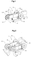
- Figures 1 and 2 show a chain link 1 of a preferred embodiment of the conveyor chain according to the invention.
- Figure 1 shows the chain link 1 in the assembled state
- Figure 2 is a partially exploded view.
- the chain link 1 has in the manner already mentioned two tabs 2 and 3, which carry a joint bearing 4 in the region of their aligned bearing ends 2.1 and 3.1 and 2.2 at their bolt ends 2.2 and 3.2 via a pin 5 and corresponding, in the bearing body of the next Chain link fastened pin stubs 5.1 and 5.2 are connected together.
- the joint bearing 4 has a spherical bearing body 6 with a through opening for receiving and securing the bolt 5 of the adjacent chain link and two bearing housing parts 8 and 9.
- the chain link 1 further comprises three rollers 10 and a support body 11 on which, for example, a (not shown) gripper is mounted.
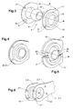
- FIG. 3 shows in a larger scale, the parts of the hinge bearing 4 of the chain link according to figures 1 and 2.
- the two bearing housing parts 8 and 9 form a step bearing for the bearing body 6, wherein the separation plane between the two bearing housing parts 8 and 9 are aligned transversely to the housing axis A Midplane is.
- Both bearing housing parts 8 and 9 have a joint socket area 15 with a through opening 16 and a on the parting plane from the socket area 15 against outwardly extending part flange 17.
- the partial flanges of the two bearing housing parts 8 and 9 are in the assembled state to each other, wherein the two part flanges 17th each half of the thickness of the entire flange make. It is not necessary that the flange is continuously around the entire pan extends. There are also a plurality of appropriately arranged, separate flange sectors conceivable.
- the bearing ends 2.1 and 3.1 of the lugs 2 and 3 have openings which are matched to the bearing cup areas 15 of the bearing housing parts 8 and 9. Further, the sub-flanges 17 of the bearing housing parts 8 and 9 are form-matched to the bearing ends 2.1 and 3.1, such that they can be aligned with the same alignment device. In the illustrated case, the flanges are the same size as the bearing ends of the tabs and have a same, substantially round shape.
- a device suitable for the alignment has, for example, a base plate and a plurality of alignment bars perpendicular to the base plate, which are arranged in a line corresponding to the outline of the partial flanges 17 and the bearing ends 2.1 and 3.1 of the flaps 2 and 3.
- the bearing housing parts 8 and 9 are securely connected to each other and include the bearing body 6 safely and on the other hand, the existing of the bearing housing parts 8 and 9 and the bearing body 6 bearing bush against rotation and against axial displacements secured to the bearing ends 2.1 and 3.1 of the tabs 2 and 3 fixed, whereby these bearing ends 2.1 and 3.1 are fixed relative to each other.
- rivets there are also other fixation than rivets conceivable, for example, screw or clamps, which are arranged in aligned grooves in the narrow sides of the flaps 2 and 3 and in the sub-flanges 17 of the bearing housing parts 8 and 9.
- the bearing housing parts 8 and 9 with matched fasteners, with the help of the two bearing housing parts 8 and 9 provisionally, ie without necessary for operation strength and, if necessary, again releasably to the bearing body 6, resulting in a preassembled bushing that can be stored and assembled as a unit.
- the fastening means are pins 30 and aligned on the pins holes 31, wherein pins and holes are formed, for example, for a press fit or snap fit.
- the two bearing housing parts 8 and 9 equipped with fastening means can also be connected to one another in a hinged manner, in the case of plastic parts, for example by means of a film hinge.
- FIG. 4 shows the bearing bush preassembled from the parts shown in FIG.
- FIG. 5 shows preassembled bearing housing parts 8 and 9, which form a bearing housing with a radial parting plane, wherein the bearing housing axis A lies in the parting plane.
- the fastening means are arranged in the region of this parting plane and consist in this case of pins 30 and corresponding holes 31.
- bearing housing parts as shown in Figure 5, are particularly suitable for a pre-assembly of the bearing bush.
- the flange of the bearing housing formed by the parts 8 and 9 is separated by the dividing plane into two partial flanges 17, each of the partial flanges 17 forming 180 ° of the entire flange. Also in this case, it is not necessary that the flange extends around the bearing cup. Also appropriately arranged, separate flange sectors can assume the flange function.
- Figure 6 shows the parts of a preassembled unit, which consists of a bearing housing part 8 or 9 and a tab 2 or 3 (only bearing end 2.1 or 3.1 shown).
- a bearing housing part 8 or 9 consists of a bearing housing part 8 or 9 and a tab 2 or 3 (only bearing end 2.1 or 3.1 shown).
- fasteners are provided, which can also consist of pins 30 'and corresponding holes 31' here.
- socket area of the bearing housing parts such that they can be snapped in place for preassembly at a bearing end of a tab or pressed fit, so that further fastening means are unnecessary.
Abstract
Description
Die Erfindung liegt auf dem Gebiete der Fördertechnik und betrifft eine Förderkette nach dem Oberbegriff des ersten unabhängigen Patentanspruchs. Die Förderkette besteht aus einer Mehrzahl von über Gelenklager miteinander verbundenen Kettengliedern, sie ist insbesondere geeignet für die Förderung von einzeln gehaltenen Druckprodukten und weist dafür Greifer auf, wobei beispielsweise an jedem Kettenglied ein Greifer angeordnet ist. Die Erfindung betrifft ferner ein Verfahren nach dem Oberbegriff des weiteren unabhängigen Patentanspruchs. Das Verfahren dient zur Montage der Kettenglieder der erfindungsgemässen Förderkette.The invention is in the field of conveyor technology and relates to a conveyor chain according to the preamble of the first independent claim. The conveyor chain consists of a plurality of interconnected via joint bearings chain links, it is particularly suitable for the promotion of individually held printed products and has for this purpose grippers, for example, a gripper is arranged on each chain link. The invention further relates to a method according to the preamble of the further independent claim. The method is used for mounting the chain links of the conveyor chain according to the invention.
Mit Förderketten aus Kettengliedern, die über Gelenklager miteinander verbunden sind, lassen sich Förderwege mit Kurven und Verdrehungen in allen Richtungen realisieren, denn durch die Gelenklager sind benachbarte Kettenglieder relativ zueinander in allen Richtungen quer zur Kettenlänge beschränkt verschwenkbar. Die Ketten werden üblicherweise in sogenannten Kettenkanälen geführt und die Kettenglieder weisen Laufrollen auf, auf denen sie auf in den Kanälen vorgesehenen Schienen abrollen.With conveyor chains of chain links, which are connected to each other via spherical bearings, conveying paths can be realized with curves and rotations in all directions, because by the joint bearings adjacent chain links are limited relative to each other in all directions transverse to the chain length pivotally. The chains are usually guided in so-called chain channels and the chain links have rollers on which they roll on rails provided in the channels.
Jedes Kettenglied einer derartigen Kette weist üblicherweise zwei Laschen auf, die sich im wesentlichen in der Kettenlängsrichtung erstrecken. Die beiden Laschen sind an ihrem einen Ende (Bolzenende) über einen Bolzen miteinander verbunden, wobei ein mittlerer Bereich des Bolzens zwischen den Bolzenenden der Laschen in einem Gelenklager gelagert ist und wobei das Gelenklager am anderen Ende (Lagerende) der Laschen eines benachbarten Kettengliedes angeordnet ist. Die beiden Laschen jedes Kettengliedes sind also an ihren Bolzenenden über den Bolzen miteinander verbunden und im Bereich ihrer Lagerenden ist das Gelenklager angeordnet, wobei der Bolzen jedes Kettengliedes durch die gelenkige Lagerung im Bereich der Lagerenden der Laschen des benachbarten Kettengliedes mit diesem verbunden ist.Each link of such a chain usually has two tabs extending substantially in the chain longitudinal direction. The two tabs are at one end (bolt end) connected to each other via a bolt, wherein a central region of the bolt between the bolt ends of the tabs is mounted in a spherical bearing and wherein the hinge bearing at the other end (bearing end) of the tabs of an adjacent chain link is arranged. The two tabs of each chain link are thus connected to each other at their bolt ends on the bolt and the spherical plain bearing is arranged in the region of its bearing ends, wherein the pin of each chain link is connected by the articulated mounting in the region of the bearing ends of the tabs of the adjacent chain link with this.
Am Bolzen jedes Kettengliedes ist üblicherweise beidseitig ausserhalb der Laschen je eine Laufrolle angeordnet. Zwischen den Bolzenenden und den Lagerenden der Laschen jedes Kettengliedes ist beispielsweise ein Tragkörper angeordnet, an dem z.B. ein Greifer montiert ist. Der Tragkörper kann zusätzlich eine dritte Laufrolle tragen, deren Achse senkrecht zum Bolzen bzw. zu den Achsen der anderen beiden Laufrollen ausgerichtet ist.On the bolt of each chain link is usually on both sides outside the tabs depending arranged a roller. Between the bolt ends and the bearing ends of the tabs of each chain link, for example, a support body is arranged, to which e.g. a gripper is mounted. The support body may additionally carry a third roller whose axis is aligned perpendicular to the bolt or to the axes of the other two rollers.
Als Gelenklager wird üblicherweise eine im Handel erhältliche Lagerbuchse verwendet, die ein eine Lagerpfanne bildendes Lagergehäuse und einen in der Lagerpfanne gefangenen und darin frei drehbaren, kugeligen Lagerkörper aufweist. Der Lagerkörper hat eine zylindrische Öffnung zur Aufnahme des Bolzens. Das Lagergehäuse ist üblicherweise zylindrisch und die Lagerpfanne weist zwei einander gegenüberliegende Öffnungen für den Durchtritt des Bolzens auf. Das Lagergehäuse wird herstellerseitig meist einstückig gefertigt, üblicherweise im Bereiche der Lagerpfanne beschichtet und um den Lagerkörper geschlossen. Lagergehäuse und Lagerkörper bilden zusammen die Lagerbuchse. Montageseitig wird dann das Lagergehäuse der Buchse mit den Lagerenden der Laschen eines Kettengliedes und der Lagerkörper der Buchse mit dem Bolzen eines benachbarten Kettengliedes verbunden. Üblicherweise werden für die Montage des Lagergehäuses an den Lagerenden der Laschen je eine Öffnung vorgesehen, die auf den Aussendurchmesser des Lagergehäuses abgestimmt sind. Die beiden Laschen werden dann aneinander befestigt, derart, dass ihre Lagerenden aneinander liegen und dass die beiden für das Lagergehäuse vorgesehenen Öffnungen aufeinander ausgerichtet sind. Die Lagerbuchse wird in den Öffnungen positioniert und durch Verstemmen wird eine Verbindung zwischen Lagergehäuse und Laschen geschaffen, derart, dass das Lagergehäuse relativ zu den Laschen weder verdreht noch in axialer Richtung verschoben werden kann.As a spherical bearing usually a commercially available bushing is used, which has a bearing cup forming a bearing housing and a trapped in the bearing cup and freely rotatable therein, spherical bearing body. The bearing body has a cylindrical opening for receiving the bolt. The bearing housing is usually cylindrical and the bearing cup has two opposing openings for the passage of the bolt. The bearing housing is usually made by the manufacturer in one piece, usually coated in the areas of the bearing cup and closed to the bearing body. Bearing housing and bearing body together form the bearing bush. On the mounting side, the bearing housing of the bush is then connected to the bearing ends of the links of a chain link and the bearing body of the bush to the bolt of an adjacent chain link. Usually, an opening is provided for the mounting of the bearing housing at the bearing ends of the tabs, which are matched to the outer diameter of the bearing housing are. The two tabs are then secured together so that their bearing ends abut each other and that the two openings provided for the bearing housing are aligned with each other. The bearing bush is positioned in the openings and by caulking a connection between the bearing housing and tabs is created, such that the bearing housing can be neither twisted relative to the tabs nor moved in the axial direction.
Die Erfindung stellt sich nun die Aufgabe, eine Förderkette aus über Gelenklager miteinander verbundenen Kettengliedern zu schaffen, wobei für die erfindungsgemässe Förderkette gegenüber bekannten derartigen Förderketten die Montage der Kettenglieder flexibler und einfacher sein soll.The invention now has the task of creating a conveyor chain of link bearings interconnected chain links, with the conveyor chain according to the invention over known such conveyor chains, the assembly of the chain links should be more flexible and easier.
Diese Aufgabe wird gelöst durch die Förderkette und durch das Verfahren zur Montage der Kettenglieder der Förderkette, wie sie in den entsprechenden Patentansprüchen definiert sind.This object is achieved by the conveyor chain and by the method for mounting the chain links of the conveyor chain, as defined in the corresponding claims.
Die erfindungsgemässe Förderkette unterscheidet sich von den weiter oben kurz beschriebenen, bekannten Förderketten aus über Gelenklager miteinander verbundenen Kettengliedern dadurch, dass die Gelenklager der Kettenglieder zweiteilige Lagergehäuse mit Flanschen aufweisen, wobei sich die Flansche in einer zur Lagergehäuseachse senkrechten Mittelebene von der Lagerpfanne gegen aussen erstrecken. Ferner weisen die Kettenglieder ein Fixiermittel auf, das an den Flanschen und an den Lagerenden der Laschen angreift und das erstens die Lagergehäuseteile zu einer den Lagerkörper fest umschliessenden Lagerpfanne zusammenhält, zweitens die Lagerenden der Laschen relativ zueinander fixiert und drittens das Lagergehäuse in einer gegen Verdrehung und axiale Verschiebung gesicherten Position in diesen Lagerenden fixiert. Das Fixiermittel, das alle die genannten Funktionen übernehmen kann, besteht beispielsweise aus einer Mehrzahl von Bohrungen durch die Flansche der Lagergehäuseteile und die Lagerenden der Laschen und Nieten, die in den Bohrungen angeordnet sind.The conveyor chain according to the invention differs from the known conveyor chains described briefly above by joint bearings connected to one another by the fact that the spherical plain bearings of the chain links have two-part bearing housings with flanges, the flanges extending outwards from the bearing cup in a central plane perpendicular to the bearing housing axis. Furthermore, the chain links on a fixing means which engages the flanges and at the bearing ends of the tabs and the first holds the bearing housing parts to a bearing body firmly enclosing bearing cup, secondly the bearing ends of the tabs fixed relative to each other and third, the bearing housing in a against rotation and fixed axial displacement secured position in these bearing ends. The fixing means, which can take on all the functions mentioned, consists for example of a plurality of holes through the flanges of the bearing housing parts and the bearing ends of the tabs and rivets disposed in the bores.
Die Flansche der Lagergehäuse entsprechen in ihrer Form vorteilhafterweise der Form der Lagerenden der Laschen, derart, dass die Lagergehäuseteile und die Laschen und gegebenenfalls darin im Voraus erstellte Bohrungen als Teil des Fixiermittels für die Montage in einfacher Weise und insbesondere in derselben Ausrichtvorrichtung aufeinander ausgerichtet werden können.The flanges of the bearing housings correspond in shape advantageously to the shape of the bearing ends of the tabs, such that the bearing housing parts and the tabs and optionally therein prepared in advance holes can be aligned as part of the fixing means for mounting in a simple manner and in particular in the same alignment device ,
Die beiden Lagergehäuseteile sind vorteilhafterweise identisch. Wenn sie zusammen ein Lagergehäuse bilden mit einer Trennebene, die eine quer zur Gehäuseachse ausgerichtete Mittelebene ist, weist jeder der Lagergehäuseteile einen Teilflansch auf, wobei die beiden Teilflansche in montiertem Zustand aneinander liegen. Ein derartiges Gelenklager wird beispielsweise wie folgt an den Lagerenden der Laschen montiert: Das Lagerende der ersten Lasche wird mittels Ausrichtvorrichtung positioniert; der erste Lagergehäuseteil wird mit der Lagerpfanne gegen oben mittels derselben Ausrichtvorrichtung auf dem bereits positionierten Lagerende und auf dieses ausgerichtet positioniert; der Lagerkörper wird in die Lagerpfanne des ersten Lagergehäuseteils gelegt; der zweite Lagergehäuseteil wird mit der Lagerpfanne gegen unten positioniert und ausgerichtet; das Lagerende der zweiten Lasche wird positioniert und ausgerichtet; und dann werden die Fixiermittel montiert.The two bearing housing parts are advantageously identical. If they together form a bearing housing with a parting plane, which is a transverse to the housing axis center plane, each of the bearing housing parts has a partial flange, wherein the two partial flanges are in the assembled state to each other. Such a hinge bearing is for example mounted as follows at the bearing ends of the tabs: The bearing end of the first tab is positioned by means of alignment; the first bearing housing part is positioned with the bearing cup against the top by means of the same alignment device on the already positioned bearing end and aligned with this; the bearing body is placed in the bearing cup of the first bearing housing part; the second bearing housing part is positioned and aligned with the bearing cup against the bottom; the bearing end of the second tab is positioned and aligned; and then the fixing means are mounted.
Um die oben kurz beschriebene Montage der Gelenklager an den Laschen der Kettenglieder der erfindungsgemässen Förderkette weiter zu vereinfachen, können die Lagergehäuseteile Befestigungsmittel aufweisen, mit denen sie mit einfachsten Mitteln und vorläufig, das heisst ohne für den Betrieb notwendige Festigkeit und gegebenenfalls wieder lösbar, um den Lagerkörper geschlossen werden können. Die derart vormontierten Lagerbuchsen können dann beispielsweise an Lager gelegt und für die Montage als je ein Teil (anstelle von drei Teilen, wie oben beschrieben) positioniert und auf die Lagerenden der Laschen ausgerichtet werden. Die vormontierten Lagerbuchsen können auch zwei in einer radialen Ebene trennbare Lagergehäuseteile aufweisen.In order to simplify the assembly of the spherical plain bearings described briefly above on the tabs of the chain links of the conveyor chain according to the invention, the bearing housing parts may have fastening means with which they with the simplest means and provisionally, ie without necessary strength for operation and, if necessary, releasably to the Bearing body can be closed. The thus preassembled bearing bushes can then be placed for example in stock and for the assembly is positioned as one part (instead of three parts as described above) and aligned with the bearing ends of the tabs. The preassembled bushings may also have two separable in a radial plane bearing housing parts.
Ebenfalls zur weiteren Vereinfachung der Montage des Gelenklagers an den Lagerenden der Laschen können auch die Lagergehäuseteile und die Lagerenden der Laschen Befestigungsmittel aufweisen, mit denen je ein Lagergehäuseteil vorläufig an einem Lagerende einer Lasche montierbar ist. In diesem Fall werden zwei vormontierte Einheiten aus je einer Lasche mit daran vormontiertem Lagergehäuseteil beispielsweise an Lager gelegt und als Einheiten aufeinander positioniert und ausgerichtet bevor sie definitiv aneinander fixiert werden.Also, to further simplify the mounting of the hinge bearing at the bearing ends of the tabs and the bearing housing parts and the bearing ends of the tabs may have fastening means with which each bearing housing part is provisionally mounted on a bearing end of a tab. In this case, two preassembled units each consisting of a tab with a bearing housing part preassembled thereon are placed in bearings, for example, and positioned and aligned as units before they are definitely fixed to one another.
Als Befestigungsmittel zur vorläufigen Fixierung von Lagergehäuseteilen aneinander oder von Lagergehäuseteilen an Laschen eignen sich insbesondere Stifte und auf die Stifte ausgerichtete Bohrungen, die für einen leichten Pressfit oder für einen Schnappfit ausgestaltet sind. Auch Klebeverbindungen können angewendet werden. Zur vorläufigen Befestigung von Lagergehäuseteilen an Laschen können die Lagerghäuseteile auch derart ausgelegt sein, dass sie in die Öffnungen der Lagerenden der Laschen einschnappbar sind.As fastening means for the provisional fixation of bearing housing parts to each other or of bearing housing parts on tabs are in particular pins and aligned on the pins holes, which are designed for a slight Pressfit or for a snap fit. Even adhesive joints can be applied. For temporary attachment of bearing housing parts to tabs, the bearing housing parts may also be designed such that they can be snapped into the openings of the bearing ends of the tabs.
Offensichtlich ist die Montage der Kettenglieder sehr einfach und sie ist insofern flexibel, als die Materialpaarungen zwischen Lagerkörper und Lagergehäuse auf der Seite der Kettenkonstruktion oder der Montage zu einem bedeutend höheren Masse frei wählbar und dadurch an die potentielle Belastung einer Kette anpassbar ist als dies mit vom Hersteller bezogenen fertigen Lagerbuchsen der Fall ist. Dabei können die Lagerkörper und Lagergehäuseteile aus einem metallischen Werkstoff oder aus Kunststoff bestehen und die Materialpaarung und gegebenenfalls eine Beschichtung der Lagerpfanne kann je Aufgabe und Belastung der Kettenglieder ausgewählt werden.Obviously, the assembly of the chain links is very simple and it is flexible in that the material pairings between the bearing body and bearing housing on the side of the chain construction or assembly to a significantly higher mass freely selectable and thereby adaptable to the potential load on a chain than with the Manufacturer related finished bearing bushes is the case. The bearing body and bearing housing parts may consist of a metallic material or of plastic and the material pairing and optionally a coating The bearing cup can be selected for each task and load on the chain links.
Die erfindungsgemässe Förderkette eignet sich, wie bereits eingangs erwähnt, insbesondere für die Förderung von einzeln gehaltenen Druckprodukten, wie Zeitungen Zeitschriften oder Broschüren, wobei beispielsweise jedes Kettenglied mit einem Greifer zum Ergreifen eines Druckproduktes ausgerüstet ist. Selbstverständlich kann eine gleiche Förderkette aber auch für andere Förderaufgaben ausgerüstet sein, wobei dann nicht unbedingt Greifer sondern andere Haltemittel oder Tragmittel an den Kettengliedern angeordnet sind und wobei nicht jedes Kettenglied mit einem solchen Mittel ausgerüstet sein muss.The inventive conveyor chain is, as already mentioned, especially for the promotion of individually held printed products, such as newspapers magazines or brochures, for example, each chain link is equipped with a gripper for gripping a printed product. Of course, the same conveyor chain but also be equipped for other promotional tasks, in which case not necessarily gripper but other holding means or suspension means are arranged on the chain links and not every chain link must be equipped with such means.
Bevorzugte Ausführungsformen der erfindungsgemässen Förderkette aus über Gelenklager miteinander verbundenen Kettengliedern werden im Zusammenhang mit den folgenden Figuren im Detail beschrieben. Dabei zeigen:
-
Figuren 1 und 2 - ein Kettenglied einer bevorzugten Ausführungsform der erfindungsgemässen Förderkette (Figur 1: in montiertem Zustand; Figur 2: teilweise explodiert dargestellt);
-
Figur 3 - die Teile des Gelenklagers des Kettengliedes gemäss
Figuren 1 und 2; -
Figur 4 - eine vormontierte Lagerbuchse für das Kettenglied gemäss
Figur 1; -
Figur 5 - die Teile einer anderen Ausführungsform der vormontierbaren Lagerbuchse;
-
Figur 6 - ein Lagergehäuseteil und ein Lagerende einer Lasche mit Befestigungsmitteln zur vorläufigen Befestigung aneinander.
- Figures 1 and 2
- a chain link of a preferred embodiment of the conveyor chain according to the invention (Figure 1: in the assembled state; Figure 2: partially exploded);
- FIG. 3
- the parts of the joint bearing of the chain link according to Figures 1 and 2;
- FIG. 4
- a preassembled bearing bush for the chain link according to Figure 1;
- FIG. 5
- the parts of another embodiment of the preassemblable bushing;
- FIG. 6
- a bearing housing part and a bearing end of a tab with fastening means for provisional attachment to each other.
Figuren 1 und 2 zeigen ein Kettenglied 1 einer bevorzugten Ausführungsform der erfindungsgemässen Förderkette. Figur 1 zeigt das Kettenglied 1 in montiertem Zustand, Figur 2 ist eine teilweise explodierte Darstellung. Das Kettenglied 1 weist in der bereits erwähnten Art zwei Laschen 2 und 3 auf, die im Bereich ihrer aufeinander ausgerichteten Lagerenden 2.1 und 3.1 ein Gelenklager 4 tragen und an ihren Bolzenenden 2.2 und 3.2 über einen Bolzen 5 bzw. über entsprechende, im Lagerkörper des nächsten Kettengliedes befestigte Bolzenstümpfe 5.1 und 5.2 miteinander verbunden sind. Das Gelenklager 4 weist einen kugeligen Lagerkörper 6 mit einer durchgehenden Öffnung zur Aufnahme und Befestigung des Bolzens 5 des benachbarten Kettengliedes auf sowie zwei Lagergehäuseteile 8 und 9. Figures 1 and 2 show a
Das Kettenglied 1 weist ferner drei Laufrollen 10 auf und einen Tragkörper 11, an dem beispielsweise ein (nicht dargestellter) Greifer montiert ist.The
Figur 3 zeigt in einem grösseren Massstab die Teile des Gelenklagers 4 des Kettengliedes gemäss Figuren 1 und 2. Die beiden Lagergehäuseteile 8 und 9 bilden eine Lagerpfanne für den Lagerkörper 6, wobei die Trennebene zwischen den beiden Lagergehäuseteilen 8 und 9 eine quer zur Gehäuseachse A ausgerichtete Mittelebene ist. Beide Lagergehäuseteile 8 und 9 weisen einen Gelenkpfannenbereich 15 mit einer durchgehenden Öffnung 16 auf und einen sich auf der Trennebene vom Gelenkpfannenbereich 15 gegen aussen erstreckenden Teilflansch 17. Die Teilflansche der beiden Lagergehäuseteile 8 und 9 liegen in montiertem Zustand aneinander an, wobei die beiden Teilflansche 17 je die Hälfte der Dicke des gesamten Flansches ausmachen. Dabei ist es nicht notwendig, dass sich der Flansch ununterbrochen um die ganze Lagerpfanne erstreckt. Es sind auch eine Mehrzahl von entsprechend angeordneten, voneinander getrennten Flanschsektoren denkbar. Figure 3 shows in a larger scale, the parts of the hinge bearing 4 of the chain link according to figures 1 and 2. The two bearing
Wie insbesondere aus der Figur 2 ersichtlich ist, weisen die Lagerenden 2.1 und 3.1 der Laschen 2 und 3 Öffnungen auf, die auf die Lagerpfannenbereiche 15 der Lagergehäuseteile 8 und 9 abgestimmt sind. Ferner sind die Teilflansche 17 der Lagergehäuseteile 8 und 9 formmässig auf die Lagerenden 2.1 und 3.1 abgestimmt, derart, dass sie mit derselben Ausrichtvorrichtung aufeinander ausgerichtet werden können. Im dargestellten Falle sind die Flansche gleich gross wie die Lagerenden der Laschen und weisen eine gleiche, im wesentlichen runde Form auf. Eine für die Ausrichtung geeignete Vorrichtung weist beispielsweise eine Grundplatte und eine Mehrzahl von senkrecht auf der Grundplatte stehenden Ausrichtstäben auf, die in einer dem Umriss der Teilflansche 17 und der Lagerenden 2.1 und 3.1 der Laschen 2 und 3 entsprechenden Linie angeordnet sind.As can be seen in particular from FIG. 2, the bearing ends 2.1 and 3.1 of the
Als Fixierungsmittel werden beispielsweise durch die aufeinander ausgerichteten Lagerenden 2.1 und 3.1 der Laschen 2 und 3 und durch die dazwischen angeordneten Teilflansche 17 der Lagergehäuseteile 7 und 8 Bohrungen 22 (Figur 2) gebohrt und darin Nieten 20 (Figur 1) angeordnet. Wenn die Lagerenden 2.1 und 3.1 der Laschen gegeneinander vorgespannt sind, reicht es, zwei Vernietungen auf der gegen das Bolzenende 2.2 und 3.2 gerichteten Seite der Lagergehäuseteile 7 und 8 anzubringen, wie es in der Figur 1 dargestellt ist. Dadurch wird es möglich, die radiale Ausdehnung der Teilflansche 17 und der Lagerenden 2.1 und 3.1 der Laschen 2 und 3 klein zu gestalten, was für viele Anwendungen vorteilhaft ist. Es ist aber auch möglich, entsprechende Bohrungen und Nieten rund um die Gelenkpfanne zu verteilen. Durch die Vernietungen sind einerseits die Lagergehäuseteile 8 und 9 sicher miteinander verbunden und schliessen den Lagerkörper 6 sicher ein und andererseits ist die aus den Lagergehäuseteilen 8 und 9 und dem Lagerkörper 6 bestehende Lagerbuchse gegen Drehungen und gegen axiale Verschiebungen gesichert an den Lagerenden 2.1 und 3.1 der Laschen 2 und 3 fixiert, wobei auch diese Lagerenden 2.1 und 3.1 relativ zueinander fixiert sind.As a fixing, for example, by the aligned bearing ends 2.1 and 3.1 of the
Selbstverständlich ist es auch möglich, die Bohrungen 22 für die Vernietung der Teilflansche 17 der Lagergehäuseteile 8 und 9 und der Lagerenden 2.1 und 3.1 der Laschen 2 und 3 in allen Teilen separat einzubringen und die aufeinander ausgerichteten Teile dann nur noch zu vernieten. Dies ist in der Figur 2 durch die Bohrungen 22 angedeutet.Of course, it is also possible to separately introduce the
Es sind auch andere Fixiermittel als Vernietungen denkbar, beispielsweise Verschraubungen oder Klemmen, die in aufeinander ausgerichteten Nuten in den Schmalseiten der Laschen 2 und 3 und in den Teilflanschen 17 der Lagergehäuseteile 8 und 9 angeordnet werden.There are also other fixation than rivets conceivable, for example, screw or clamps, which are arranged in aligned grooves in the narrow sides of the
Wie in Figur 3 dargestellt, ist es auch möglich, die Lagergehäuseteile 8 und 9 mit aufeinander abgestimmten Befestigungsmitteln zu versehen, mit deren Hilfe die beiden Lagergehäuseteile 8 und 9 vorläufig, das heisst ohne für den Betrieb notwendige Festigkeit und gegebenenfalls wieder lösbar, um den Lagerkörper 6 zu schliessen, wodurch eine vormontierte Lagerbuchse entsteht, die an Lager gelegt und als Einheit montiert werden kann. Im dargestellten Falle sind die Befestigungsmittel Stifte 30 und auf die Stifte ausgerichtete Bohrungen 31, wobei Stifte und Bohrungen beispielsweise für einen Pressfit oder einen Schnappfit ausgebildet sind.As shown in Figure 3, it is also possible to provide the bearing
Wie in der Figur 3 durch den Doppelpfeil B angedeutet, können die beiden mit Befestigungsmitteln ausgerüsteten Lagergehäuseteile 8 und 9 auch scharnierend miteinander verbunden sein, im Falle von Kunststoffteilen beispielweise mittels Filmscharnier.As indicated in FIG. 3 by the double arrow B, the two bearing
Figur 4 zeigt die aus den in der Figur 3 dargestellten Teilen vormontierte Lagerbuchse. FIG. 4 shows the bearing bush preassembled from the parts shown in FIG.
Figur 5 zeigt vormontierbare Lagergehäuseteile 8 und 9, die ein Lagergehäuse mit einer radialen Trennebene bilden, wobei die Lagergehäuseachse A in der Trennebene liegt. Die Befestigungsmittel sind im Bereiche dieser Trennebene angeordnet und bestehen auch in diesem Falle aus Stiften 30 und entsprechenden Bohrungen 31. Offensichtlich eignen sich Lagergehäuseteile, wie sie in der Figur 5 dargestellt sind, insbesondere für eine Vormontage der Lagerbuchse. Der Flansch des durch die Teile 8 und 9 gebildeten Lagergehäuses ist durch die Trennebene in zwei Teilflansche 17 getrennt, wobei jeder der Teilflansche 17 180° des ganzen Flansches bildet. Auch in diesem Falle ist es nicht notwendig, dass der Flansch sich rund um die Lagerpfanne erstreckt. Auch entsprechend angeordnete, voneinander getrennte Flanschsektoren können die Flanschfunktion übernehmen. FIG. 5 shows preassembled bearing
Figur 6 zeigt die Teile einer vormontierten Einheit, die aus einem Lagergehäuseteil 8 oder 9 und einer Lasche 2 oder 3 (nur Lagerende 2.1 oder 3.1 dargestellt) besteht. Für die Vormontage sind Befestigungsmittel vorgesehen, die auch hier aus Stiften 30' und entsprechenden Bohrungen 31' bestehen können. Es ist aber auch möglich, den Gelenkpfannenbereich der Lagergehäuseteile derart auszugestalten, dass sie für die Vormontage an einem Lagerende einer Lasche einschnappbar oder mittel Pressfit einsteckbar sind, so dass sich weitere Befestigungsmittel erübrigen. Figure 6 shows the parts of a preassembled unit, which consists of a bearing
Claims (13)
Priority Applications (1)
| Application Number | Priority Date | Filing Date | Title |
|---|---|---|---|
| PL07405062T PL1832532T3 (en) | 2006-03-08 | 2007-02-27 | Chain conveyor comprising chain links connected to each other via rocker bearings and method for mounting chain links |
Applications Claiming Priority (1)
| Application Number | Priority Date | Filing Date | Title |
|---|---|---|---|
| CH3672006 | 2006-03-08 |
Publications (3)
| Publication Number | Publication Date |
|---|---|
| EP1832532A2 true EP1832532A2 (en) | 2007-09-12 |
| EP1832532A3 EP1832532A3 (en) | 2009-01-21 |
| EP1832532B1 EP1832532B1 (en) | 2010-03-24 |
Family
ID=38169615
Family Applications (1)
| Application Number | Title | Priority Date | Filing Date |
|---|---|---|---|
| EP07405062A Active EP1832532B1 (en) | 2006-03-08 | 2007-02-27 | Chain conveyor comprising chain links connected to each other via rocker bearings and method for mounting chain links |
Country Status (7)
| Country | Link |
|---|---|
| US (1) | US7334677B2 (en) |
| EP (1) | EP1832532B1 (en) |
| AT (1) | ATE461891T1 (en) |
| CA (1) | CA2579853C (en) |
| DE (1) | DE502007003192D1 (en) |
| ES (1) | ES2343377T3 (en) |
| PL (1) | PL1832532T3 (en) |
Cited By (5)
| Publication number | Priority date | Publication date | Assignee | Title |
|---|---|---|---|---|
| EP2325113A1 (en) | 2009-11-18 | 2011-05-25 | Müller Martini Holding AG | Transport body for transporting printed products |
| WO2011147039A1 (en) | 2010-05-26 | 2011-12-01 | Müller Martini Holding AG | Pivot bearing |
| WO2012088615A2 (en) | 2010-12-27 | 2012-07-05 | Ferag Ag | Conveying chain for a conveying device |
| CN102758879A (en) * | 2012-07-26 | 2012-10-31 | 株洲职业技术学院 | Universal bending transmission chain |
| IT202100004976A1 (en) * | 2021-03-03 | 2022-09-03 | Rad Hub S R L | FRUIT OR VEGETABLE TRANSPORT SYSTEM |
Families Citing this family (10)
| Publication number | Priority date | Publication date | Assignee | Title |
|---|---|---|---|---|
| JP5160789B2 (en) * | 2004-02-02 | 2013-03-13 | クロネス・アクチェンゲゼルシャフト | Dynamic storage device for goods |
| DE202004016069U1 (en) | 2004-10-16 | 2005-12-01 | Krones Ag | Device for buffering objects |
| DE202005013552U1 (en) | 2005-08-27 | 2005-11-03 | Krones Ag | Dynamic storage for buffering and transporting empty bottle, has lower deflection pulleys rotating in essentially horizontal planes and connected with vertical loops by curved guides for conveyor chain |
| DE102006008123A1 (en) * | 2006-02-20 | 2007-08-23 | Krones Ag | Dynamic conveyor holding zone, for items being carried, has two conveyor paths moving in opposite directions with a transfer unit to move them from one to the other and a control unit linked to sensors |
| DE102006012148A1 (en) * | 2006-03-16 | 2007-09-20 | Krones Ag | funding |
| DE102006035109A1 (en) * | 2006-07-29 | 2008-01-31 | Krones Ag | Conveyor device for use in bottle handling device, has conveyors separated from each other and connected with buffer over transferring points, where intermediate conveyor bypasses buffer |
| US7954631B1 (en) | 2008-09-23 | 2011-06-07 | Weaverline, LLC | Chain link conveyor for use in material handling equipment |
| US20140262699A1 (en) * | 2013-03-15 | 2014-09-18 | Irwin Research And Development, Inc. | Thermoforming Chain Rail Having Compact Anti-Torque Chain Support |
| US10533634B2 (en) * | 2016-07-26 | 2020-01-14 | AMF automation Technologies, LLC | Axle and bearing for conveyor chain link |
| US10550881B2 (en) * | 2016-07-26 | 2020-02-04 | AMF automation Technologies, LLC | Axle and bearing for conveyor chain link |
Citations (6)
| Publication number | Priority date | Publication date | Assignee | Title |
|---|---|---|---|---|
| GB588483A (en) * | 1945-02-21 | 1947-05-22 | Silentbloc | Improvements in or relating to flexible chains |
| GB906751A (en) * | 1960-04-22 | 1962-09-26 | Lars Benndahl | Improvements in or relating to conveyor chains |
| FR1356773A (en) * | 1963-05-15 | 1964-03-27 | Demag Zug Gmbh | Traction unit, in particular chain link for conveyor devices |
| GB1032792A (en) * | 1963-01-09 | 1966-06-15 | Salzgitter Maschinen Ag | Improvements in and relating to articulated conveyors |
| FR2319818A1 (en) * | 1975-07-28 | 1977-02-25 | Ferag Ag | LINK CHAIN WITH SPHERICAL ARTICULATIONS |
| US5129506A (en) * | 1988-10-20 | 1992-07-14 | Izdatelstvo "Izvestia Sovetov Narodnykh Deputatov Sssr" | Space conveyor for newspaper, books and magazines |
Family Cites Families (7)
| Publication number | Priority date | Publication date | Assignee | Title |
|---|---|---|---|---|
| US3278000A (en) * | 1964-12-14 | 1966-10-11 | Anson Ind Inc L | Conveyor chain with disconnectable ball bearing link joints |
| US4050323A (en) * | 1976-01-12 | 1977-09-27 | Anson Thomas I | Pintle-type industrial conveyor chain |
| US4766997A (en) * | 1986-12-24 | 1988-08-30 | The Budd Company | Bearing for a conveyor chain |
| GB9907173D0 (en) * | 1999-03-30 | 1999-05-26 | Renold Plc | A chain |
| DE19941306C1 (en) * | 1999-08-31 | 2001-01-18 | Monforts Textilmaschinen Gmbh | Stenter roller chain has a sealing ring at the inner ball bearing ring with metallic inserts keyed against rotation at the inner strap and aligned passages and channels for the lubricant flow |
| US6666328B2 (en) * | 2001-08-07 | 2003-12-23 | Stapell/Guider Corporation | Long wear conveyor assembly |
| US6978886B2 (en) * | 2003-07-29 | 2005-12-27 | Globe Composite Solutions, Ltd. | Non-metallic drive chain |
-
2007
- 2007-02-27 CA CA2579853A patent/CA2579853C/en not_active Expired - Fee Related
- 2007-02-27 ES ES07405062T patent/ES2343377T3/en active Active
- 2007-02-27 EP EP07405062A patent/EP1832532B1/en active Active
- 2007-02-27 PL PL07405062T patent/PL1832532T3/en unknown
- 2007-02-27 AT AT07405062T patent/ATE461891T1/en active
- 2007-02-27 DE DE502007003192T patent/DE502007003192D1/en active Active
- 2007-03-06 US US11/682,491 patent/US7334677B2/en not_active Expired - Fee Related
Patent Citations (6)
| Publication number | Priority date | Publication date | Assignee | Title |
|---|---|---|---|---|
| GB588483A (en) * | 1945-02-21 | 1947-05-22 | Silentbloc | Improvements in or relating to flexible chains |
| GB906751A (en) * | 1960-04-22 | 1962-09-26 | Lars Benndahl | Improvements in or relating to conveyor chains |
| GB1032792A (en) * | 1963-01-09 | 1966-06-15 | Salzgitter Maschinen Ag | Improvements in and relating to articulated conveyors |
| FR1356773A (en) * | 1963-05-15 | 1964-03-27 | Demag Zug Gmbh | Traction unit, in particular chain link for conveyor devices |
| FR2319818A1 (en) * | 1975-07-28 | 1977-02-25 | Ferag Ag | LINK CHAIN WITH SPHERICAL ARTICULATIONS |
| US5129506A (en) * | 1988-10-20 | 1992-07-14 | Izdatelstvo "Izvestia Sovetov Narodnykh Deputatov Sssr" | Space conveyor for newspaper, books and magazines |
Cited By (9)
| Publication number | Priority date | Publication date | Assignee | Title |
|---|---|---|---|---|
| EP2325113A1 (en) | 2009-11-18 | 2011-05-25 | Müller Martini Holding AG | Transport body for transporting printed products |
| US8534455B2 (en) | 2009-11-18 | 2013-09-17 | Muller Martini Holding Ag | Transporting device for conveying printed products |
| WO2011147039A1 (en) | 2010-05-26 | 2011-12-01 | Müller Martini Holding AG | Pivot bearing |
| US8529133B2 (en) | 2010-05-26 | 2013-09-10 | Mueller Martini Holding Ag | Pivot bearing |
| WO2012088615A2 (en) | 2010-12-27 | 2012-07-05 | Ferag Ag | Conveying chain for a conveying device |
| CN102758879A (en) * | 2012-07-26 | 2012-10-31 | 株洲职业技术学院 | Universal bending transmission chain |
| CN102758879B (en) * | 2012-07-26 | 2013-12-11 | 株洲职业技术学院 | Universal bending transmission chain |
| IT202100004976A1 (en) * | 2021-03-03 | 2022-09-03 | Rad Hub S R L | FRUIT OR VEGETABLE TRANSPORT SYSTEM |
| EP4053049A1 (en) * | 2021-03-03 | 2022-09-07 | Rad-Hub S.r.l. | Fruit or vegetable transport system |
Also Published As
| Publication number | Publication date |
|---|---|
| ES2343377T3 (en) | 2010-07-29 |
| EP1832532A3 (en) | 2009-01-21 |
| ATE461891T1 (en) | 2010-04-15 |
| US7334677B2 (en) | 2008-02-26 |
| CA2579853C (en) | 2014-01-21 |
| DE502007003192D1 (en) | 2010-05-06 |
| CA2579853A1 (en) | 2007-09-08 |
| PL1832532T3 (en) | 2010-10-29 |
| EP1832532B1 (en) | 2010-03-24 |
| US20070209911A1 (en) | 2007-09-13 |
Similar Documents
| Publication | Publication Date | Title |
|---|---|---|
| EP1832532B1 (en) | Chain conveyor comprising chain links connected to each other via rocker bearings and method for mounting chain links | |
| EP0861387B1 (en) | Chain link of a power transmission chain with additional element | |
| EP3682050B1 (en) | Conveyor device for a folding device for folding textiles | |
| EP0686748B1 (en) | Pinless and maintenance free sheet-metal hinge for vehicles | |
| WO2008040295A1 (en) | Metal cage for roller bearings | |
| WO2013174666A1 (en) | Belt end body or belt segment end body | |
| EP2740677A1 (en) | Transport device for deep draw packaging machine | |
| DE102011100048A1 (en) | Hinge for vehicle flap | |
| WO2019161422A1 (en) | Holder for a dipping mould | |
| WO2008000249A1 (en) | Bearing cage comprising a plurality of connecting links | |
| DE202006020934U1 (en) | conveyor chain | |
| DE3116173A1 (en) | SUPPORTING DEVICES WITH AT LEAST ONE PARABEL-SHAPED SPRING SHEET AND AT LEAST ONE BRACKET COMPRESSING THE MIDDLE OF THE SPRING | |
| DE102016101466B4 (en) | Bicycle brake | |
| EP1952035B1 (en) | Assembled crankshaft | |
| WO2007071490A1 (en) | Fastening apparatus | |
| DE4216072A1 (en) | CHAIN CONNECTOR | |
| EP2147875A2 (en) | Actuator | |
| DE102017114452A1 (en) | Planet carrier, planetary gear and method for manufacturing a planet carrier | |
| EP1849723B1 (en) | Conveyor chain | |
| DE102021106748A1 (en) | Chain link and plate chain | |
| DE19907306C1 (en) | Conveyor chain comprises paired, parallel, alternating inner plates and outer plates with holes having non-circular cross-section in ends of inner plates | |
| EP1710451A1 (en) | Fixing arrangement for connecting tubes in a cross-shaped or T-shaped arrangement and tubular frames with tubes connected in such a way | |
| DE102018205506A1 (en) | Connection of a steering in the power flow of the longitudinal member | |
| DE19934998A1 (en) | Detachable connecting element has shaft with spiral spring, clamping elements and ends | |
| EP1120367B1 (en) | Accumulating roller conveyor chain |
Legal Events
| Date | Code | Title | Description |
|---|---|---|---|
| PUAI | Public reference made under article 153(3) epc to a published international application that has entered the european phase |
Free format text: ORIGINAL CODE: 0009012 |
|
| AK | Designated contracting states |
Kind code of ref document: A2 Designated state(s): AT BE BG CH CY CZ DE DK EE ES FI FR GB GR HU IE IS IT LI LT LU LV MC NL PL PT RO SE SI SK TR |
|
| AX | Request for extension of the european patent |
Extension state: AL BA HR MK YU |
|
| PUAL | Search report despatched |
Free format text: ORIGINAL CODE: 0009013 |
|
| AK | Designated contracting states |
Kind code of ref document: A3 Designated state(s): AT BE BG CH CY CZ DE DK EE ES FI FR GB GR HU IE IS IT LI LT LU LV MC NL PL PT RO SE SI SK TR |
|
| AX | Request for extension of the european patent |
Extension state: AL BA HR MK RS |
|
| RIC1 | Information provided on ipc code assigned before grant |
Ipc: F16G 13/10 20060101ALI20081216BHEP Ipc: B65G 17/38 20060101AFI20070709BHEP |
|
| 17P | Request for examination filed |
Effective date: 20090703 |
|
| AKX | Designation fees paid |
Designated state(s): AT BE BG CH CY CZ DE DK EE ES FI FR GB GR HU IE IS IT LI LT LU LV MC NL PL PT RO SE SI SK TR |
|
| GRAP | Despatch of communication of intention to grant a patent |
Free format text: ORIGINAL CODE: EPIDOSNIGR1 |
|
| GRAS | Grant fee paid |
Free format text: ORIGINAL CODE: EPIDOSNIGR3 |
|
| GRAA | (expected) grant |
Free format text: ORIGINAL CODE: 0009210 |
|
| AK | Designated contracting states |
Kind code of ref document: B1 Designated state(s): AT BE BG CH CY CZ DE DK EE ES FI FR GB GR HU IE IS IT LI LT LU LV MC NL PL PT RO SE SI SK TR |
|
| REG | Reference to a national code |
Ref country code: GB Ref legal event code: FG4D Free format text: NOT ENGLISH |
|
| REG | Reference to a national code |
Ref country code: CH Ref legal event code: EP |
|
| REG | Reference to a national code |
Ref country code: IE Ref legal event code: FG4D |
|
| REF | Corresponds to: |
Ref document number: 502007003192 Country of ref document: DE Date of ref document: 20100506 Kind code of ref document: P |
|
| REG | Reference to a national code |
Ref country code: CH Ref legal event code: NV Representative=s name: FREI PATENTANWALTSBUERO AG |
|
| REG | Reference to a national code |
Ref country code: DK Ref legal event code: T3 |
|
| REG | Reference to a national code |
Ref country code: NL Ref legal event code: T3 |
|
| REG | Reference to a national code |
Ref country code: SE Ref legal event code: TRGR |
|
| REG | Reference to a national code |
Ref country code: ES Ref legal event code: FG2A Ref document number: 2343377 Country of ref document: ES Kind code of ref document: T3 |
|
| PG25 | Lapsed in a contracting state [announced via postgrant information from national office to epo] |
Ref country code: LT Free format text: LAPSE BECAUSE OF FAILURE TO SUBMIT A TRANSLATION OF THE DESCRIPTION OR TO PAY THE FEE WITHIN THE PRESCRIBED TIME-LIMIT Effective date: 20100324 |
|
| LTIE | Lt: invalidation of european patent or patent extension |
Effective date: 20100324 |
|
| PG25 | Lapsed in a contracting state [announced via postgrant information from national office to epo] |
Ref country code: LV Free format text: LAPSE BECAUSE OF FAILURE TO SUBMIT A TRANSLATION OF THE DESCRIPTION OR TO PAY THE FEE WITHIN THE PRESCRIBED TIME-LIMIT Effective date: 20100324 Ref country code: SI Free format text: LAPSE BECAUSE OF FAILURE TO SUBMIT A TRANSLATION OF THE DESCRIPTION OR TO PAY THE FEE WITHIN THE PRESCRIBED TIME-LIMIT Effective date: 20100324 |
|
| REG | Reference to a national code |
Ref country code: SK Ref legal event code: T3 Ref document number: E 7473 Country of ref document: SK |
|
| PG25 | Lapsed in a contracting state [announced via postgrant information from national office to epo] |
Ref country code: GR Free format text: LAPSE BECAUSE OF FAILURE TO SUBMIT A TRANSLATION OF THE DESCRIPTION OR TO PAY THE FEE WITHIN THE PRESCRIBED TIME-LIMIT Effective date: 20100625 Ref country code: EE Free format text: LAPSE BECAUSE OF FAILURE TO SUBMIT A TRANSLATION OF THE DESCRIPTION OR TO PAY THE FEE WITHIN THE PRESCRIBED TIME-LIMIT Effective date: 20100324 Ref country code: RO Free format text: LAPSE BECAUSE OF FAILURE TO SUBMIT A TRANSLATION OF THE DESCRIPTION OR TO PAY THE FEE WITHIN THE PRESCRIBED TIME-LIMIT Effective date: 20100324 |
|
| REG | Reference to a national code |
Ref country code: PL Ref legal event code: T3 |
|
| PG25 | Lapsed in a contracting state [announced via postgrant information from national office to epo] |
Ref country code: BG Free format text: LAPSE BECAUSE OF FAILURE TO SUBMIT A TRANSLATION OF THE DESCRIPTION OR TO PAY THE FEE WITHIN THE PRESCRIBED TIME-LIMIT Effective date: 20100624 Ref country code: IS Free format text: LAPSE BECAUSE OF FAILURE TO SUBMIT A TRANSLATION OF THE DESCRIPTION OR TO PAY THE FEE WITHIN THE PRESCRIBED TIME-LIMIT Effective date: 20100724 |
|
| PLBE | No opposition filed within time limit |
Free format text: ORIGINAL CODE: 0009261 |
|
| STAA | Information on the status of an ep patent application or granted ep patent |
Free format text: STATUS: NO OPPOSITION FILED WITHIN TIME LIMIT |
|
| PG25 | Lapsed in a contracting state [announced via postgrant information from national office to epo] |
Ref country code: PT Free format text: LAPSE BECAUSE OF FAILURE TO SUBMIT A TRANSLATION OF THE DESCRIPTION OR TO PAY THE FEE WITHIN THE PRESCRIBED TIME-LIMIT Effective date: 20100726 |
|
| 26N | No opposition filed |
Effective date: 20101228 |
|
| PG25 | Lapsed in a contracting state [announced via postgrant information from national office to epo] |
Ref country code: MC Free format text: LAPSE BECAUSE OF NON-PAYMENT OF DUE FEES Effective date: 20110228 |
|
| PGFP | Annual fee paid to national office [announced via postgrant information from national office to epo] |
Ref country code: FI Payment date: 20130213 Year of fee payment: 7 Ref country code: CZ Payment date: 20130222 Year of fee payment: 7 Ref country code: IE Payment date: 20130219 Year of fee payment: 7 Ref country code: GB Payment date: 20130218 Year of fee payment: 7 Ref country code: FR Payment date: 20130301 Year of fee payment: 7 Ref country code: ES Payment date: 20130227 Year of fee payment: 7 |
|
| PG25 | Lapsed in a contracting state [announced via postgrant information from national office to epo] |
Ref country code: LU Free format text: LAPSE BECAUSE OF NON-PAYMENT OF DUE FEES Effective date: 20110227 Ref country code: CY Free format text: LAPSE BECAUSE OF FAILURE TO SUBMIT A TRANSLATION OF THE DESCRIPTION OR TO PAY THE FEE WITHIN THE PRESCRIBED TIME-LIMIT Effective date: 20100324 |
|
| PGFP | Annual fee paid to national office [announced via postgrant information from national office to epo] |
Ref country code: SK Payment date: 20130226 Year of fee payment: 7 Ref country code: NL Payment date: 20130219 Year of fee payment: 7 Ref country code: PL Payment date: 20130124 Year of fee payment: 7 Ref country code: BE Payment date: 20130220 Year of fee payment: 7 |
|
| PG25 | Lapsed in a contracting state [announced via postgrant information from national office to epo] |
Ref country code: TR Free format text: LAPSE BECAUSE OF FAILURE TO SUBMIT A TRANSLATION OF THE DESCRIPTION OR TO PAY THE FEE WITHIN THE PRESCRIBED TIME-LIMIT Effective date: 20100324 |
|
| PG25 | Lapsed in a contracting state [announced via postgrant information from national office to epo] |
Ref country code: HU Free format text: LAPSE BECAUSE OF FAILURE TO SUBMIT A TRANSLATION OF THE DESCRIPTION OR TO PAY THE FEE WITHIN THE PRESCRIBED TIME-LIMIT Effective date: 20100324 |
|
| BERE | Be: lapsed |
Owner name: FERAG AG Effective date: 20140228 |
|
| REG | Reference to a national code |
Ref country code: NL Ref legal event code: V1 Effective date: 20140901 |
|
| GBPC | Gb: european patent ceased through non-payment of renewal fee |
Effective date: 20140227 |
|
| PG25 | Lapsed in a contracting state [announced via postgrant information from national office to epo] |
Ref country code: CZ Free format text: LAPSE BECAUSE OF NON-PAYMENT OF DUE FEES Effective date: 20140227 Ref country code: FI Free format text: LAPSE BECAUSE OF NON-PAYMENT OF DUE FEES Effective date: 20140227 Ref country code: NL Free format text: LAPSE BECAUSE OF NON-PAYMENT OF DUE FEES Effective date: 20140901 |
|
| REG | Reference to a national code |
Ref country code: SK Ref legal event code: MM4A Ref document number: E 7473 Country of ref document: SK Effective date: 20140227 |
|
| REG | Reference to a national code |
Ref country code: FR Ref legal event code: ST Effective date: 20141031 |
|
| PG25 | Lapsed in a contracting state [announced via postgrant information from national office to epo] |
Ref country code: SK Free format text: LAPSE BECAUSE OF NON-PAYMENT OF DUE FEES Effective date: 20140227 |
|
| REG | Reference to a national code |
Ref country code: IE Ref legal event code: MM4A |
|
| PG25 | Lapsed in a contracting state [announced via postgrant information from national office to epo] |
Ref country code: BE Free format text: LAPSE BECAUSE OF NON-PAYMENT OF DUE FEES Effective date: 20140228 Ref country code: FR Free format text: LAPSE BECAUSE OF NON-PAYMENT OF DUE FEES Effective date: 20140228 Ref country code: GB Free format text: LAPSE BECAUSE OF NON-PAYMENT OF DUE FEES Effective date: 20140227 Ref country code: IE Free format text: LAPSE BECAUSE OF NON-PAYMENT OF DUE FEES Effective date: 20140227 |
|
| REG | Reference to a national code |
Ref country code: ES Ref legal event code: FD2A Effective date: 20150406 |
|
| PG25 | Lapsed in a contracting state [announced via postgrant information from national office to epo] |
Ref country code: ES Free format text: LAPSE BECAUSE OF NON-PAYMENT OF DUE FEES Effective date: 20140228 |
|
| PG25 | Lapsed in a contracting state [announced via postgrant information from national office to epo] |
Ref country code: PL Free format text: LAPSE BECAUSE OF NON-PAYMENT OF DUE FEES Effective date: 20140227 |
|
| REG | Reference to a national code |
Ref country code: PL Ref legal event code: LAPE |
|
| REG | Reference to a national code |
Ref country code: DE Ref legal event code: R082 Ref document number: 502007003192 Country of ref document: DE Representative=s name: PATENTANWAELTE UND RECHTSANWALT DR. WEISS, ARA, DE Ref country code: DE Ref legal event code: R082 Ref document number: 502007003192 Country of ref document: DE Representative=s name: PATENTANWAELTE UND RECHTSANWALT WEISS, ARAT & , DE |
|
| PGFP | Annual fee paid to national office [announced via postgrant information from national office to epo] |
Ref country code: DK Payment date: 20160217 Year of fee payment: 10 |
|
| PGFP | Annual fee paid to national office [announced via postgrant information from national office to epo] |
Ref country code: SE Payment date: 20170216 Year of fee payment: 11 |
|
| PGFP | Annual fee paid to national office [announced via postgrant information from national office to epo] |
Ref country code: AT Payment date: 20170217 Year of fee payment: 11 |
|
| PGFP | Annual fee paid to national office [announced via postgrant information from national office to epo] |
Ref country code: IT Payment date: 20170221 Year of fee payment: 11 |
|
| REG | Reference to a national code |
Ref country code: DK Ref legal event code: EBP Effective date: 20170228 |
|
| PG25 | Lapsed in a contracting state [announced via postgrant information from national office to epo] |
Ref country code: DK Free format text: LAPSE BECAUSE OF NON-PAYMENT OF DUE FEES Effective date: 20170228 |
|
| REG | Reference to a national code |
Ref country code: SE Ref legal event code: EUG |
|
| REG | Reference to a national code |
Ref country code: AT Ref legal event code: MM01 Ref document number: 461891 Country of ref document: AT Kind code of ref document: T Effective date: 20180227 |
|
| PG25 | Lapsed in a contracting state [announced via postgrant information from national office to epo] |
Ref country code: SE Free format text: LAPSE BECAUSE OF NON-PAYMENT OF DUE FEES Effective date: 20180228 |
|
| PG25 | Lapsed in a contracting state [announced via postgrant information from national office to epo] |
Ref country code: AT Free format text: LAPSE BECAUSE OF NON-PAYMENT OF DUE FEES Effective date: 20180227 |
|
| PG25 | Lapsed in a contracting state [announced via postgrant information from national office to epo] |
Ref country code: IT Free format text: LAPSE BECAUSE OF NON-PAYMENT OF DUE FEES Effective date: 20180227 |
|
| PGFP | Annual fee paid to national office [announced via postgrant information from national office to epo] |
Ref country code: DE Payment date: 20230216 Year of fee payment: 17 |
|
| P01 | Opt-out of the competence of the unified patent court (upc) registered |
Effective date: 20230526 |
|
| PGFP | Annual fee paid to national office [announced via postgrant information from national office to epo] |
Ref country code: CH Payment date: 20230425 Year of fee payment: 17 |