EP1832495B1 - Vorrichtung zur Lagerung eines Modulträgers am Lenkrad eines Kraftfahrzeugs - Google Patents
Vorrichtung zur Lagerung eines Modulträgers am Lenkrad eines Kraftfahrzeugs Download PDFInfo
- Publication number
- EP1832495B1 EP1832495B1 EP07101786A EP07101786A EP1832495B1 EP 1832495 B1 EP1832495 B1 EP 1832495B1 EP 07101786 A EP07101786 A EP 07101786A EP 07101786 A EP07101786 A EP 07101786A EP 1832495 B1 EP1832495 B1 EP 1832495B1
- Authority
- EP
- European Patent Office
- Prior art keywords
- lever
- arm
- toothed
- wheel
- toothed ring
- Prior art date
- Legal status (The legal status is an assumption and is not a legal conclusion. Google has not performed a legal analysis and makes no representation as to the accuracy of the status listed.)
- Not-in-force
Links
- 210000003811 finger Anatomy 0.000 description 2
- 230000004048 modification Effects 0.000 description 2
- 238000012986 modification Methods 0.000 description 2
- 238000005452 bending Methods 0.000 description 1
- 230000008878 coupling Effects 0.000 description 1
- 238000010168 coupling process Methods 0.000 description 1
- 238000005859 coupling reaction Methods 0.000 description 1
- 238000009434 installation Methods 0.000 description 1
- 238000004519 manufacturing process Methods 0.000 description 1
- 239000012815 thermoplastic material Substances 0.000 description 1
- 210000003813 thumb Anatomy 0.000 description 1
Images


Classifications
-
- B—PERFORMING OPERATIONS; TRANSPORTING
- B62—LAND VEHICLES FOR TRAVELLING OTHERWISE THAN ON RAILS
- B62D—MOTOR VEHICLES; TRAILERS
- B62D1/00—Steering controls, i.e. means for initiating a change of direction of the vehicle
- B62D1/02—Steering controls, i.e. means for initiating a change of direction of the vehicle vehicle-mounted
- B62D1/04—Hand wheels
- B62D1/10—Hubs; Connecting hubs to steering columns, e.g. adjustable
- B62D1/105—Non-rotatable hubs, e.g. the central part of the steering wheel not rotating
-
- Y—GENERAL TAGGING OF NEW TECHNOLOGICAL DEVELOPMENTS; GENERAL TAGGING OF CROSS-SECTIONAL TECHNOLOGIES SPANNING OVER SEVERAL SECTIONS OF THE IPC; TECHNICAL SUBJECTS COVERED BY FORMER USPC CROSS-REFERENCE ART COLLECTIONS [XRACs] AND DIGESTS
- Y10—TECHNICAL SUBJECTS COVERED BY FORMER USPC
- Y10T—TECHNICAL SUBJECTS COVERED BY FORMER US CLASSIFICATION
- Y10T74/00—Machine element or mechanism
- Y10T74/20—Control lever and linkage systems
- Y10T74/20207—Multiple controlling elements for single controlled element
- Y10T74/20256—Steering and controls assemblies
-
- Y—GENERAL TAGGING OF NEW TECHNOLOGICAL DEVELOPMENTS; GENERAL TAGGING OF CROSS-SECTIONAL TECHNOLOGIES SPANNING OVER SEVERAL SECTIONS OF THE IPC; TECHNICAL SUBJECTS COVERED BY FORMER USPC CROSS-REFERENCE ART COLLECTIONS [XRACs] AND DIGESTS
- Y10—TECHNICAL SUBJECTS COVERED BY FORMER USPC
- Y10T—TECHNICAL SUBJECTS COVERED BY FORMER US CLASSIFICATION
- Y10T74/00—Machine element or mechanism
- Y10T74/20—Control lever and linkage systems
- Y10T74/20576—Elements
- Y10T74/20732—Handles
- Y10T74/20834—Hand wheels
Definitions
- the invention relates to a device for the rotatable mounting of a module carrier on the steering wheel of a motor vehicle according to the preamble of claim 1.
- Such a device serves to mount a module carrier, in particular a module carrier for a gas bag module, on a steering wheel of a motor vehicle rotatable about a steering axis such that the angular position of the module carrier remains constant during a rotation of the steering wheel about the steering axis, e.g. in the event of a crash, always to ensure an optimal, reproducible positioning of an inflatable gas bag which can be deployed out of the gas bag module.
- the module carrier can carry a display module whose displays are always easy to read due to the constant angular position of the module carrier in the room.
- such a device comprises a rotatably connected to the module carrier first sprocket, a lever which is pivotally mounted about a bearing portion of the lever on the steering wheel between two positions and a first gear which is spaced from the bearing portion at a first connected to the bearing portion Arm of the lever is rotatably mounted and in a first position of the lever meshes with the first ring gear, wherein elastic means are provided which are adapted to press the first gear elastically against the first ring gear.
- the first gear acts in such a way with the steering wheel, that a rotation of the steering wheel in one direction causes rotation of the connected to the first sprocket module carrier in the opposite direction, so that the angular position of the module carrier remains constant in a vehicle-fixed coordinate system.
- the first gear is pressed by means of the lever elastically against the first ring gear, a conditional by manufacturing tolerances and tension during operation game of the above gear pairing is compensated.
- Such a device is known from DE 3435021 known.
- the invention is based on the problem to provide a device of the type mentioned in such a way that a simple and quick installation of the device is possible.
- the lever for actuating the lever has a second arm which is connected via the bearing portion of the lever to the first arm of the lever.
- the first toothed wheel mounted on the lever can advantageously be brought into or out of engagement with the first toothed rim during assembly or disassembly.
- the second arm of the lever is formed as a manually operable actuator adapted and arranged to manually pivot the lever from the first position to a second position (and vice versa) with the first gear in the second position is out of engagement with the first sprocket.
- the second arm is widened at a free end transverse to an extension direction of the second arm along which the second arm extends longitudinally.
- the second arm designed as an actuating element can advantageously be actuated in a simple manner by means of a fingertip, for example with the first phalanx of a thumb or by means of a suitable tool.
- the first arm of the lever on which the first gear is mounted formed along this extension direction extends longitudinally, ie, it is preferably aligned with the second arm of the lever.
- the The first arm and the second arm along the extension direction in terms of amount substantially the same length.
- a releasably attachable to the steering wheel fixing element is provided, which is adapted to pivoting out of the lever from the first position such that the first gear of the lever mounted first gear does not touch the first sprocket to limit.
- the fixing element is preferably designed to limit the pivoting out in such a way that the first toothed wheel does not disengage from the first toothed rim.
- the fixing preferably passes through a continuous recess which is formed at a free end portion of the second arm, wherein the inner diameter of the recess is larger than the outer diameter of the fixing in the region of this recess.
- the inner diameter of the recess is larger than the outer diameter of the fixing element by such a degree that the lever can perform about its first position around a pivoting movement, which serves the clearance compensation of the interlocking teeth of the first ring gear and the first gear, wherein the lever the fixing element can not be swung out so far from the first position that the first gear can be disengaged from the first ring gear.
- the lever is pivotally mounted on a hub of the steering wheel, via which the steering wheel about the steering axis is rotatably mounted on the motor vehicle stored.
- the second arm actuator
- the second arm is formed or mounted on the hub, that it is arranged along the steering axis spaced from the hub exposed.
- space for manual actuation of the second arm formed as an actuating element is advantageously created.
- the second arm may be obscured or enveloped by other components of the device.
- the elastic means are coupled to the lever such that it presses the first gear in the first position of the lever elastically against the first ring gear.
- elastic means in the form of a torsion spring are preferably provided.
- the torsion spring is fixed to the lever via a first free section of the torsion spring and via a second free end section to the hub of the steering wheel.
- this axis of rotation runs parallel to the steering axis of the steering wheel.
- the first gear is rotatably supported via a shaft on the first arm of the lever.
- the first arm preferably has a U-shaped bearing recess into which the shaft is preferably clipped.
- the bearing recess surrounds the shaft in the clipped (or engaged) state in cross section at least in sections such that the shaft can be brought out of engagement with the bearing recess only by bending the bearing recess, ie by applying a force.
- the shaft is parallel to the steering axis.
- the first gear is connected via the shaft with a second gear.
- the first gear may be integrally connected to the second gear.
- Such a pair of planetary gears may for example be made of a thermoplastic material.
- the hub spaced from the steering axis on a recess through which the shaft is guided.
- the two gears are thus arranged along the steering axis on both sides of the hub.
- a second sprocket is provided, which is designed for non-rotatable mounting on the motor vehicle and meshes with the second gear of the planetary gear pair.
- This second sprocket z. B. be arranged on a steering column or a panel of the steering column.
- the two sprockets are arranged coaxially to the steering axis, wherein preferably the outer diameter of the second sprocket is equal in magnitude to the outer diameter of the first sprocket.
- the two sprockets have the same number of teeth.
- the two gears preferably have the same number of teeth and have a magnitude equal in outer diameter.
- the second gear is configured and intended to mesh with the second sprocket.
- the elastic means cooperate with the lever such that it also presses the second gear in the first position of the lever elastically against the second sprocket.
- the first sprocket mounted on the module carrier and the second sprocket fastened on the vehicle side are coupled together by the pair of planetary gears formed from the first gear and the second gear and the shaft, so that rotation of the steering wheel in one direction causes rotation of the module carrier connected to the first sprocket causes opposite direction, in such a way that the angular position of the module carrier remains constant in a vehicle-fixed coordinate system.
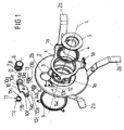
- FIG. 1 shows in connection with FIGS. 2 to 5 a device for mounting a module carrier 1 on a hub 2 of a steering wheel, which is rotatably mounted on a motor vehicle about a steering axis L.
- the device comprises a coaxial with the steering axis L arranged first sprocket 3, which is rotatably connected to a side facing away from a driver of the module carrier 1.
- the module carrier 1 is formed substantially annular and rotates the steering axis L transverse to this.
- the module carrier 1 For fastening a module to the module carrier 1, the module carrier 1 has three fastening elements 1a which protrude from the module carrier 1 along the steering axis L (in the direction of a driver). According to its annular design, the module carrier 1 has a continuous recess which is aligned with a recess of the hub 2, wherein the recess serves to receive a ring-shaped ball bearing 4, via which the module carrier 1 is rotatably mounted on the hub 2. For fixing the ball bearing 4, a clamping ring 5 is provided, which is pressed to set the ball bearing 4 along the steering axis L via a screw, not shown, against the ball bearing 4.
- the hub 2 is formed substantially flat and extends in a direction perpendicular to the steering axis L extending plane. From an outer circumferential edge of the hub 2 are spaced from each other along the edge spoke segments 2a from the hub 2, which form together with the hub 2 a part of a steering wheel skeleton attached to the free end portions of the spoke segments 2a a steering wheel rim skeleton or a steering wheel rim can be.
- the hub 2 has a recess 2b continuous along the steering axis L and spaced transversely of the steering axis L therefrom, such that the spacing between the steering axis L and a center of the recess 2b is greater than an outer radius of the first ring gear 3 with respect to the steering axis L.
- a Planetenradstand is introduced, which has a first gear 6 and another, parallel to the gear 6 arranged second gear 7, via a along the steering axis L. extending shaft 8 are interconnected.
- the pair of planetary gears is arranged in the recess 2b of the hub 2 in such a way that the first gear wheel 6 of the planetary gear pair is in engagement with the first ring gear 3, which is fixed on the side of the module carrier 1 facing the hub 2.
- the hub 2 is arranged behind the first gear 6 along the steering axis L as viewed by a driver, and the second gear 7 connected to the first gear 6 via the shaft 8 is behind the hub 2 along the steering axis L as viewed by a driver arranged and is in engagement with a second ring gear 9, which is rotatably connected to the motor vehicle, such as the steering column connected.
- the hub 2 is rotatably mounted on the motor vehicle such that it is arranged along the steering axis L between the module carrier-fixed first ring gear 3 and the vehicle-fixed second ring gear 9.
- the two sprockets (sun gears) 3, 9 are coupled together via the Planetenradbin whose shaft 8 along the steering axis L through the recess 2b of the hub 2 extends therethrough.
- the outer diameter of the first sprocket 3 and the second sprocket 9 and the number of teeth equal.
- the Planetenradstand is about the two gears 6, 7 interconnecting shaft 8 by means of a lever 10 mounted on the hub 2, so that the first and the second gear 6, 7 of the Planetenradpreses about a parallel to the steering axis L extending axis of rotation D, with the shaft 8 is aligned, are rotatable.
- the lever 10 serves to press the first gear 6 and the second gear 7 for combing with the first ring gear 3 and the second ring gear 9 elastically against these two sprockets 3, 9. As a result, a game between the gear pairs first gear 6 / first sprocket 3 on the one hand and second gear 7 / second sprocket 9 on the other balanced.
- the lever 10 is formed with two arms and accordingly has a first arm 10a with a free end portion 10e, on which a continuous bearing recess 10d is formed, in which the shaft 8 is rotatably supported about the axis of rotation D.
- the first arm 10a of the lever 10 is connected via a bearing portion 10b of the lever 10, via which the lever 10 is pivotally mounted on the hub 2 about a parallel to the steering axis L extending axis of rotation D ', with a second arm 10c opposite to the first Arm 10a from the bearing portion 10b of the lever 10 protrudes.
- the force by means of which the first arm 10a of the lever 10 presses the pair of planetary gears with the two toothed wheels 6, 7 against the two toothed rings 3, 9 along a direction perpendicular to the steering axis L is provided by a torsion spring 11.
- the torsion spring 11 has a first free end portion 11 a, via which it is attached to the lever 10 and which is connected via a central portion 11 b of the torsion spring 11 with a second free end portion 11 c of the torsion spring 11, via which the torsion spring 11 on the Hub 2 is set.
- the hub 2 has a recess 12 for receiving both the central portion 11 b and the second free end portion 11 a of the torsion spring 11.
- the lever 10 is pivotally mounted on the hub 2 via its bearing portion 10b by means of a pin 13 aligned with the axis of rotation D '.
- the bolt 13 passes through a recess 13a of the bearing area 10b and is fixed with a free end portion 13b in a recess 13c formed in the recess 12 of the hub 2.
- the bolt 13 may for example be formed as a screw which is screwed with its threaded end portion 13 b in the recess 13 c.
- the middle portion 11b of the torsion spring 11 is wound along the rotation axis D 'of the lever 10 between the lever 10 and the hub 2 around the bolt 13, i.e., about the rotation axis D'.
- the outgoing from the bearing portion 10b second arm 10c of the lever 10 is formed as a manually operable actuator, via which the lever 10 can be pivoted against the force provided by the torsion spring 11 in a second position in which the Planetenradhigh disengaged from the two sprockets 3, 9 is.
- the actuating element 10c is pressed along a direction perpendicular to the steering axis L direction to the first ring gear 3 out.
- This second position of the lever 10 corresponds to a mounting position in which the device can be easily assembled or disassembled.
- the hub 2 and the module carrier 1 can be particularly easily arranged in their intended positions, since the Planetenradpress in the second position of the lever 10, the positioning of these components of the device with respect to the second ring gear 9 and the hub 2 (in the case of the module carrier 1) not hindered.
- the actuating element 10c can be fixed by means of a fixing element 14 designed as a bolt, which for this purpose engages in a continuous recess 14a of a free end region 10f of the actuating element 10c and is releasably secured to a free end region 14b in a recess 14c of the hub 2 (for example by screwing with the recess 14c).
- a fixing element 14 designed as a bolt, which for this purpose engages in a continuous recess 14a of a free end region 10f of the actuating element 10c and is releasably secured to a free end region 14b in a recess 14c of the hub 2 (for example by screwing with the recess 14c).
- the fixation of the actuating element 10c by means of the bolt 14 takes place in the first position of the lever 10, in such a way that the lever 10 in the fixed state can perform a pivoting movement about its axis of rotation D ', which is limited by the pin 14, that the on the first arm 10a of the lever 10 mounted first gear 6 and the second gear 7 mounted there just can not disengage from the first ring gear 3 and the second ring gear 9 can pass.
- the rotational movement of the shaft 8 generated about its axis of rotation D is transmitted to the first ring gear 3 by means of the first gear 6 of the pair of planetary gears, which performs an identical (directional) movement to the second gear 7, such that the rotational movement of the first ring gear 3 to the rotational movement of the two gears 6, 7 and thus also the steering wheel or the hub 2 in opposite directions (reverse gear).
- the module carrier 1 connected to the first ring gear 3 is rotated relative to the hub 2 (steering wheel) in the opposite direction.
- the two gears 6, 7 and the two sprockets 3, 9 are formed in terms of their number and dimensions such that the angle of rotation of the steering wheel or the hub 2 with respect to the second sprocket 9 in terms of amount is substantially identical to the rotation angle of the module carrier 1 in the opposite direction.
- Rotation of the hub 2 in one direction thus causes a rotation of the mounted on the hub 2 module carrier 1 relative to the hub 2 in the opposite direction, by the same rotational angle, so that the angular position of the rotatably mounted on the hub 2 module carrier 1 in a vehicle-fixed coordinate system remains constant.
- FIG. 6 shows a modification of the in the FIGS. 1 to 5 shown device for mounting a module carrier 1 on a steering wheel.
- the lever 10 is held in the first position only by the force exerted by the elastic means 11 on the lever 10 in which the first arm 10a of the lever 10 mounted gears 6, 7 for combing with the two sprockets 3, 9 against this be pressed.
- the second arm 10c of the lever 10 which is formed as an actuating element, ergonomically has at a free end portion 10f a broadening, which is set up and provided for actuating the actuating element 10c by finger pressure.
- a broadening which is set up and provided for actuating the actuating element 10c by finger pressure.
- FIG. 7 shows an exploded view of the lever 10 of FIG. 6 with the elastic means (spring means) formed as a torsion spring 11, the bolt 13 for the pivotal mounting of the lever 10 about the axis of rotation D ', and the integrally formed Planetenradpres consisting of the first gear 6 and the second gear 7, via the cylindrical Shaft 8 are connected to each other.
- the first arm 10a has at its free end 10e a U-shaped, the first sprocket 3 facing bearing recess 10d ', in which the shaft 8 of the Planetenradschreibes according to FIG. 8 and FIG. 9 is clipped, so that the shaft 8 is encompassed by the first arm 10a of the lever 10 such that it is rotatably fixed in the bearing recess 10d 'about the rotation axis D.
Landscapes
- Engineering & Computer Science (AREA)
- Chemical & Material Sciences (AREA)
- Combustion & Propulsion (AREA)
- Transportation (AREA)
- Mechanical Engineering (AREA)
- Steering Controls (AREA)
- Retarders (AREA)
- Power Steering Mechanism (AREA)
Applications Claiming Priority (1)
| Application Number | Priority Date | Filing Date | Title |
|---|---|---|---|
| DE202006003920U DE202006003920U1 (de) | 2006-03-07 | 2006-03-07 | Vorrichtung zur Lagerung eines Modulträgers am Lenkrad eines Kraftfahrzeugs |
Publications (3)
| Publication Number | Publication Date |
|---|---|
| EP1832495A2 EP1832495A2 (de) | 2007-09-12 |
| EP1832495A3 EP1832495A3 (de) | 2007-10-24 |
| EP1832495B1 true EP1832495B1 (de) | 2008-10-22 |
Family
ID=36571599
Family Applications (1)
| Application Number | Title | Priority Date | Filing Date |
|---|---|---|---|
| EP07101786A Not-in-force EP1832495B1 (de) | 2006-03-07 | 2007-02-06 | Vorrichtung zur Lagerung eines Modulträgers am Lenkrad eines Kraftfahrzeugs |
Country Status (5)
| Country | Link |
|---|---|
| US (1) | US7673898B2 (ja) |
| EP (1) | EP1832495B1 (ja) |
| JP (1) | JP4625818B2 (ja) |
| CN (1) | CN101032939B (ja) |
| DE (2) | DE202006003920U1 (ja) |
Families Citing this family (2)
| Publication number | Priority date | Publication date | Assignee | Title |
|---|---|---|---|---|
| ITUA20164342A1 (it) * | 2016-06-14 | 2017-12-14 | I F R A S R L | Apparato per variare la direzione di avanzamento di un veicolo, in particolare di un veicolo nautico. |
| CN115366986A (zh) * | 2022-08-15 | 2022-11-22 | 南京农业大学 | 一种可快速拆装的后装型自动转向控制机器人 |
Family Cites Families (8)
| Publication number | Priority date | Publication date | Assignee | Title |
|---|---|---|---|---|
| JPS59118547A (ja) * | 1982-12-24 | 1984-07-09 | Toyoda Gosei Co Ltd | ステアリングホイ−ル |
| US4598603A (en) * | 1983-08-29 | 1986-07-08 | Toyoda Gosei Co., Ltd. | Steering wheel |
| US4602523A (en) | 1983-09-27 | 1986-07-29 | Nissan Motor Company, Ltd. | Steering system equipped with anti-rotation mechanism |
| US4729254A (en) * | 1985-03-14 | 1988-03-08 | Isumi Corporation Industries, Inc. | Steering system |
| US4796482A (en) * | 1985-06-10 | 1989-01-10 | Toyoda Gosei Co., Ltd. | Steering wheel |
| JPS6416459U (ja) * | 1987-07-22 | 1989-01-26 | ||
| DE10118663A1 (de) | 2001-04-14 | 2002-10-17 | Zf Lenksysteme Gmbh | Betätigungseinrichtung für ein Fahrzeug-Lenkeinrichtung |
| DE10320328B4 (de) | 2003-05-06 | 2007-09-27 | C. Rob. Hammerstein Gmbh & Co. Kg | Untersetzungsgetriebe für eine Verstellvorrichtung eines Kraftfahrzeugsitzes |
-
2006
- 2006-03-07 DE DE202006003920U patent/DE202006003920U1/de not_active Expired - Lifetime
-
2007
- 2007-02-06 EP EP07101786A patent/EP1832495B1/de not_active Not-in-force
- 2007-02-06 DE DE502007000175T patent/DE502007000175D1/de active Active
- 2007-03-06 JP JP2007056251A patent/JP4625818B2/ja not_active Expired - Fee Related
- 2007-03-07 US US11/715,138 patent/US7673898B2/en not_active Expired - Fee Related
- 2007-03-07 CN CN2007100855029A patent/CN101032939B/zh not_active Expired - Fee Related
Also Published As
| Publication number | Publication date |
|---|---|
| US7673898B2 (en) | 2010-03-09 |
| CN101032939A (zh) | 2007-09-12 |
| JP4625818B2 (ja) | 2011-02-02 |
| JP2007238087A (ja) | 2007-09-20 |
| EP1832495A2 (de) | 2007-09-12 |
| DE502007000175D1 (de) | 2008-12-04 |
| EP1832495A3 (de) | 2007-10-24 |
| CN101032939B (zh) | 2012-09-05 |
| DE202006003920U1 (de) | 2006-05-18 |
| US20070209470A1 (en) | 2007-09-13 |
Similar Documents
| Publication | Publication Date | Title |
|---|---|---|
| DE102004011268B3 (de) | Neigungsverstellbeschlag für die Rückenlehne eines Kraftfahrzeugsitzes | |
| EP2735767A1 (de) | Verdrehspielfreies Planetengetriebe mit zueinander vorgespannten Planetenträgern | |
| EP0743221A2 (de) | Verstellmechanismus für Kraftfahrzeugsitze | |
| DE3938967C2 (de) | Baueinheit zur antriebsmäßigen Verbindung einer Landmaschine mit einem Traktor und zur Anhängung derselben an den Traktor | |
| DE2254841A1 (de) | Gelenkbeschlag fuer eine verstellbare rueckenlehne, insbesondere von kraftfahrzeugsitzen | |
| EP4359172B1 (de) | Drehmomentwerkzeug | |
| DE102009051107B3 (de) | Lager zur drehbaren Lagerung einer Lenkspindel | |
| EP2064465B1 (de) | Getriebevorrichtung | |
| EP2191172B1 (de) | Schalteinheit für ein schaltgetriebe eines kraftfahrzeugs | |
| EP4286261A1 (de) | Lenksystem für fahrradlenker mit lenkanschlagseinrichtung | |
| WO2017032662A1 (de) | Klemmvorrichtung einer verstellbaren lenksäule für kraftfahrzeuge | |
| DE102018217459A1 (de) | Lenkgetriebe und Lenksystem für ein Kraftfahrzeug | |
| DE102006042322A1 (de) | Scheibenwischeranlage mit einem Scheibenwischerantrieb, insbesondere für einen Heckscheibenwischer eines Kraftfahrzeugs mit einer modular austauschbaren Getriebeanordnung | |
| DE102016122644A1 (de) | Lenkgetriebe und Lenksystem | |
| EP1832495B1 (de) | Vorrichtung zur Lagerung eines Modulträgers am Lenkrad eines Kraftfahrzeugs | |
| DE102017211461B4 (de) | Lenkgetriebe | |
| EP0698524B1 (de) | Einstellbare Armstütze für Kraftfahrzeuge | |
| DE10144143C1 (de) | Torsionsmodul für eine Drehmomenterfassungseinrichtung | |
| EP1732785A1 (de) | Airbaganordnung sowie getriebe und betriebsverfahren dafür | |
| DE102008004324B4 (de) | Scheibenwischeranlage an einem Fahrzeug | |
| DE102021119522A1 (de) | Chirurgisches Instrument und Lenkgetriebe dafür | |
| DE102007027753A1 (de) | Zugmittelmechanismus, insbesondere für verstellbare Fahrzeugsitze | |
| DE19720860A1 (de) | Beidseitig wirkender Antrieb | |
| DE102010050561A1 (de) | Exzenterhülse, Getriebe, Lenksystem und Kraftfahrzeug | |
| DE4038345C1 (en) | Vehicle seat with adjustable lumbar support - has reduction gearing on drive for positioning cushion support |
Legal Events
| Date | Code | Title | Description |
|---|---|---|---|
| PUAI | Public reference made under article 153(3) epc to a published international application that has entered the european phase |
Free format text: ORIGINAL CODE: 0009012 |
|
| AK | Designated contracting states |
Kind code of ref document: A2 Designated state(s): AT BE BG CH CY CZ DE DK EE ES FI FR GB GR HU IE IS IT LI LT LU LV MC NL PL PT RO SE SI SK TR |
|
| AX | Request for extension of the european patent |
Extension state: AL BA HR MK YU |
|
| PUAL | Search report despatched |
Free format text: ORIGINAL CODE: 0009013 |
|
| AK | Designated contracting states |
Kind code of ref document: A3 Designated state(s): AT BE BG CH CY CZ DE DK EE ES FI FR GB GR HU IE IS IT LI LT LU LV MC NL PL PT RO SE SI SK TR |
|
| AX | Request for extension of the european patent |
Extension state: AL BA HR MK YU |
|
| 17P | Request for examination filed |
Effective date: 20071106 |
|
| GRAP | Despatch of communication of intention to grant a patent |
Free format text: ORIGINAL CODE: EPIDOSNIGR1 |
|
| GRAS | Grant fee paid |
Free format text: ORIGINAL CODE: EPIDOSNIGR3 |
|
| AKX | Designation fees paid |
Designated state(s): DE FR GB SE |
|
| GRAA | (expected) grant |
Free format text: ORIGINAL CODE: 0009210 |
|
| AK | Designated contracting states |
Kind code of ref document: B1 Designated state(s): DE FR GB SE |
|
| REG | Reference to a national code |
Ref country code: GB Ref legal event code: FG4D Free format text: NOT ENGLISH |
|
| REF | Corresponds to: |
Ref document number: 502007000175 Country of ref document: DE Date of ref document: 20081204 Kind code of ref document: P |
|
| PLBE | No opposition filed within time limit |
Free format text: ORIGINAL CODE: 0009261 |
|
| STAA | Information on the status of an ep patent application or granted ep patent |
Free format text: STATUS: NO OPPOSITION FILED WITHIN TIME LIMIT |
|
| PG25 | Lapsed in a contracting state [announced via postgrant information from national office to epo] |
Ref country code: SE Free format text: LAPSE BECAUSE OF FAILURE TO SUBMIT A TRANSLATION OF THE DESCRIPTION OR TO PAY THE FEE WITHIN THE PRESCRIBED TIME-LIMIT Effective date: 20090122 |
|
| 26N | No opposition filed |
Effective date: 20090723 |
|
| GBPC | Gb: european patent ceased through non-payment of renewal fee |
Effective date: 20110206 |
|
| PG25 | Lapsed in a contracting state [announced via postgrant information from national office to epo] |
Ref country code: GB Free format text: LAPSE BECAUSE OF NON-PAYMENT OF DUE FEES Effective date: 20110206 |
|
| PGFP | Annual fee paid to national office [announced via postgrant information from national office to epo] |
Ref country code: FR Payment date: 20120221 Year of fee payment: 6 |
|
| PGFP | Annual fee paid to national office [announced via postgrant information from national office to epo] |
Ref country code: DE Payment date: 20120131 Year of fee payment: 6 |
|
| REG | Reference to a national code |
Ref country code: DE Ref legal event code: R082 Ref document number: 502007000175 Country of ref document: DE Representative=s name: MAIKOWSKI & NINNEMANN PATENTANWAELTE, DE |
|
| REG | Reference to a national code |
Ref country code: DE Ref legal event code: R082 Ref document number: 502007000175 Country of ref document: DE Representative=s name: MAIKOWSKI & NINNEMANN PATENTANWAELTE, DE Effective date: 20120904 Ref country code: DE Ref legal event code: R081 Ref document number: 502007000175 Country of ref document: DE Owner name: TAKATA AKTIENGESELLSCHAFT, DE Free format text: FORMER OWNER: TAKATA-PETRI AG, 63743 ASCHAFFENBURG, DE Effective date: 20120904 |
|
| REG | Reference to a national code |
Ref country code: FR Ref legal event code: ST Effective date: 20131031 |
|
| REG | Reference to a national code |
Ref country code: DE Ref legal event code: R119 Ref document number: 502007000175 Country of ref document: DE Effective date: 20130903 |
|
| PG25 | Lapsed in a contracting state [announced via postgrant information from national office to epo] |
Ref country code: DE Free format text: LAPSE BECAUSE OF NON-PAYMENT OF DUE FEES Effective date: 20130903 Ref country code: FR Free format text: LAPSE BECAUSE OF NON-PAYMENT OF DUE FEES Effective date: 20130228 |