EP1832408B1 - Thermoforming method and thermoforming machine with toggle mechanism - Google Patents
Thermoforming method and thermoforming machine with toggle mechanism Download PDFInfo
- Publication number
- EP1832408B1 EP1832408B1 EP07004213A EP07004213A EP1832408B1 EP 1832408 B1 EP1832408 B1 EP 1832408B1 EP 07004213 A EP07004213 A EP 07004213A EP 07004213 A EP07004213 A EP 07004213A EP 1832408 B1 EP1832408 B1 EP 1832408B1
- Authority
- EP
- European Patent Office
- Prior art keywords
- thermoforming machine
- tool
- toggle lever
- toggle
- motion
- Prior art date
- Legal status (The legal status is an assumption and is not a legal conclusion. Google has not performed a legal analysis and makes no representation as to the accuracy of the status listed.)
- Not-in-force
Links
Images


Classifications
-
- B—PERFORMING OPERATIONS; TRANSPORTING
- B29—WORKING OF PLASTICS; WORKING OF SUBSTANCES IN A PLASTIC STATE IN GENERAL
- B29C—SHAPING OR JOINING OF PLASTICS; SHAPING OF MATERIAL IN A PLASTIC STATE, NOT OTHERWISE PROVIDED FOR; AFTER-TREATMENT OF THE SHAPED PRODUCTS, e.g. REPAIRING
- B29C51/00—Shaping by thermoforming, i.e. shaping sheets or sheet like preforms after heating, e.g. shaping sheets in matched moulds or by deep-drawing; Apparatus therefor
- B29C51/26—Component parts, details or accessories; Auxiliary operations
- B29C51/30—Moulds
- B29C51/38—Opening, closing or clamping means
-
- B—PERFORMING OPERATIONS; TRANSPORTING
- B26—HAND CUTTING TOOLS; CUTTING; SEVERING
- B26D—CUTTING; DETAILS COMMON TO MACHINES FOR PERFORATING, PUNCHING, CUTTING-OUT, STAMPING-OUT OR SEVERING
- B26D5/00—Arrangements for operating and controlling machines or devices for cutting, cutting-out, stamping-out, punching, perforating, or severing by means other than cutting
- B26D5/08—Means for actuating the cutting member to effect the cut
- B26D5/18—Toggle-link means
-
- B—PERFORMING OPERATIONS; TRANSPORTING
- B26—HAND CUTTING TOOLS; CUTTING; SEVERING
- B26F—PERFORATING; PUNCHING; CUTTING-OUT; STAMPING-OUT; SEVERING BY MEANS OTHER THAN CUTTING
- B26F1/00—Perforating; Punching; Cutting-out; Stamping-out; Apparatus therefor
- B26F1/38—Cutting-out; Stamping-out
- B26F1/40—Cutting-out; Stamping-out using a press, e.g. of the ram type
Abstract
Description
Die Erfindung betrifft eine Thermoformmaschine und ein Verfahren zum Betreiben einer Thermoformmaschine zum Formen und Stanzen von Artikeln aus einer thermoplastischen Kunststofffolie, die ein mindestens zweiteiliges Werkzeug aufweist, von denen mindestens eines der jeweils von einem Werkzeugtisch getragenen Werkzeuge in eine Öffnungs- und Schließrichtung mittels eines Bewegungselements verstellbar ist, wobei das Bewegungselement aus zwei zu einer Mittenebene zumindest eines Teils der Thermoformmaschine spiegelbildlich angeordneten Kniehebelsystemen besteht.The invention relates to a thermoforming machine and a method for operating a thermoforming machine for molding and stamping articles of a thermoplastic plastic film having an at least two-part tool, of which at least one of each supported by a tool table tools in an opening and closing direction by means of a moving member is adjustable, wherein the moving element consists of two to a central plane of at least a portion of the thermoforming machine mirror-inverted knee lever systems.
Mit solchen Thermoformmaschinen werden zwischen den relativ zueinander beweglichen Teilen eines Werkzeugs Kunststoffartikel (beispielsweise Margarineschalen, Trinkbecher, Behälterdeckel) aus thermoplastischen Kunststofffolien und Verbundfolien produziert. Dabei werden in der geschlossenen Stellung des aus Ober- und Unter-Werkzeug bestehenden Werkzeugs die Artikel geformt, indem die erwärmte Folie mit Druckluft oder Vakuum in die Werkzeugkavität gedrückt wird, dann gestanzt und anschließend bei geöffneter Stellung des Werkzeugs aus diesem heraus und in eine nachgeschaltete Stapel- und Zählvorrichtung gefördert wird. Das Oberwerkzeug ist ebenso wie das Unterwerkzeug an je einen höhenbeweglichen Tisch befestigt, so daß beide Werkzeugteile verstellbar sind.With such thermoforming machines, plastic articles (for example, margarine bowls, drinking cups, container lids) made of thermoplastic plastic films and composite films are produced between the relatively movable parts of a tool. In this case, in the closed position of the tool consisting of upper and lower tools, the articles are shaped by pressing the heated film with compressed air or vacuum into the mold cavity, then punched and then with the tool in the open position out of this and into a downstream one Stacking and counting device is promoted. The upper tool is as well as the lower tool attached to a respective height-adjustable table, so that both tool parts are adjustable.
Eine Thermoformmaschine der gattungsgemäßen Art ist aus der
Aus der
Ein anderer Nachteil besteht darin, dass sich die Rollenspindelantriebe wegen der notwendigen zentralen Krafteinleitung in der Mitte des Werkzeugs bzw. Werkzeugtisches befinden müssen. Dort muss jedoch bei einigen Typen von Thermoformmaschinen der sog. Vorstrecker angeordnet werden, der eine mechanische Vorausformung der erwärmten Kunststofffolie vornimmt. Der Vorstrecker wird besonders für hohe Artikel benötigt. Ist der Vorstrecker nicht - was aufwändig ist - im Werkzeug integriert, muss er mittig bzw. zentral in der Thermoformmaschine positioniert werden, so dass hier entsprechender Platz zur Verfügung stehen muss. Der Vorstrecker muss dabei in der Regel eine von der Bewegung des Werkzeugtisches unabhängige Bewegung ausführen können.Another disadvantage is that the roller spindle drives must be located in the middle of the tool or tool table because of the necessary central force application. There, however, in some types of thermoforming machines, the so-called pre-stretchers must be arranged, which performs a mechanical pre-forming of the heated plastic film. The pre-straightener is especially needed for high items. If the pre-expander is not - which is expensive - integrated in the tool, it must be positioned centrally or centrally in the thermoforming machine, so that the appropriate space must be available here. The pre-straightener must be able to perform an independent of the movement of the tool table movement in the rule.
Bei den bekannten Antrieben, sei es z.B. mit den beschriebenen Pneumatikzylindern oder Rollenspindeln, liegt ein weiterer, wesentlicher Nachteil vor. Dieser besteht in der unvermeidlichen Umkehr der Bewegungen nach Beendigung des Stanzvorgangs, was immer mit einem Stopp des Antriebssystems einhergeht. Es sind beim Thermoformen nämlich drei Arbeitswege der Formtische mit ihren Form- und Werkzeughälften unabdingbar. Die Werkzeughälfte fährt von der unteren Position auf die Folie zu und taucht dabei bis auf einen Restweg von wenigen zehntel Millimetern in die Folie ein, um diese druckdicht abzudichten. Hier hält das Antriebssystem das erste mal an. Die Formzeit für das Produkt läuft an, bis die Artikel ausgekühlt sind. Danach startet erneut der Antrieb, um die Artikel auszustanzen. Der Weg des Tisches mit dem Werkzeug beträgt nur wenige zehntel Millimeter, wobei die Drehrichtung des Antriebes oder der Verfahrweg der Zylinder gleich ist. Die Folie wird nun durchgestanzt, wonach ein zweiter Stopp erforderlich ist, weil die Bewegung der Antriebe umgekehrt werden muß, damit diese wieder in ihre Ausgangsposition gelangen, wo sich zur Einleitung eines neuen Arbeitszyklusses ein dritter Stopp anschließt. Dabei treten erhebliche Zeitverluste auf durch Verzögerungs- und Beschleunigungsrampen, was durch das Hochlaufen der Motoren zwangsweise abläuft, oder durch Umsteuern der Druckluft auf die andere Kolbenfläche in den Zylindern.In the known drives, be it for example with the described pneumatic cylinders or roller spindles, there is a further significant disadvantage. This is the inevitable reversal of the movements after punching has been completed, which is always accompanied by a stop of the drive system. It is indispensable in thermoforming namely three working paths of the molding table with their mold and tool halves. The tool half moves from the lower position to the film and dives into the film until it reaches a residual distance of a few tenths of a millimeter in order to seal it in a pressure-tight manner. Here the drive system stops for the first time. The molding time for the product starts until the articles have cooled down. Thereafter, the drive starts again to punch out the articles. The path of the table with the tool is only a few tenths of a millimeter, with the direction of rotation of the drive or the travel of the cylinder is the same. The film is now punched through, after which a second stop is required, because the movement of the drives must be reversed so that they return to their original position, where followed by the initiation of a new cycle a third stop. Significant time losses occur due to deceleration and acceleration ramps, which is caused by run-up the engines forcibly expires, or by reversing the compressed air to the other piston surface in the cylinders.
Eine andere Ausgestaltung des Bewegungselements für ein Werkzeugteil sieht vor, dass ein Servomotor über eine Getriebeanordnung ein Kniehebelsystem betätigt, das die Werkzeugtische ebenfalls in die erforderliche Position bewegt. Die beiden gleichgerichteten Kniehebelsysteme werden von einem Pleuel gleichsinnig und simultan bewegt.Another embodiment of the movement element for a tool part provides that a servomotor actuates a toggle lever system via a gear arrangement, which also moves the tool tables into the required position. The two rectified toggle lever systems are moved by a connecting rod in the same direction and simultaneously.
Dieses Kniehebelsystem hat den Nachteil, dass mit einem einzigen Antrieb beide gleichgerichteten Kniehebelpaare in eine Richtung senkrecht zur Öffnungs- und Schließbewegung des Werkzeugteils verfahren werden müssen. Dies erzeugt Massenkräfte, die senkrecht zur Öffnungs- und Schließbewegung der Maschine wirken, was ein Kippen der gesamten Form- bzw. Stanzstation nach sich zieht. Die Führungssäulen der Werkzeugteile sind nicht in der Lage, diese Kräfte und Verformungen störungsfrei aufzunehmen. Die negative Folge ist nicht nur ein höherer Verschleiß auf die Führungssäulen und Buchsen, sondern auch die Standzeiten der Bandstähle zum Ausschneiden der Artikel sind erheblich geringer. Beim Arbeiten mit Bandstählen ist die Parallelität der beiden Werkzeughälften von großer Wichtigkeit, was durch die hohen seitlichen Massenkräfte beeinträchtigt wird. Daher sind Thermoformmaschinen dieser Art nur mit einer begrenzten Taktfrequenz betreibbar. Ein weiterer Nachteil dieser Bauform ist, dass für besonders unterschiedliche Öffnungs- und Schließhübe ein Umbau der Maschine erfolgen muss.This toggle lever system has the disadvantage that with a single drive both rectified toggle lever pairs must be moved in a direction perpendicular to the opening and closing movement of the tool part. This creates inertia forces that act perpendicular to the opening and closing movement of the machine, resulting in a tilting of the entire forming or stamping station. The guide columns of the tool parts are not able to absorb these forces and deformations without interference. The negative consequence is not only a higher wear on the guide columns and bushes, but also the service life of the strip steel for cutting the articles are considerably lower. When working with strip steel, the parallelism of the two tool halves of great importance, which is affected by the high lateral mass forces. Therefore, thermoforming machines of this type are operable only with a limited clock frequency. Another disadvantage of this design is that a conversion of the machine must be made for very different opening and closing strokes.
Daher liegt der Erfindung die Aufgabe zugrunde, eine Thermoformmaschine der eingangs genannten Art ohne diese Nachteile zu schaffen, die eine hohe Taktfrequenz ermöglicht, ohne störende Seitenkräfte infolge der Kniehebel-Massenkräfte arbeitet und die schließlich hinreichenden Platz für die Anordnung eines Vorstreckers lässt, sowie ein Verfahren zum Betreiben einer solchen Thermoformmaschine vorzuschlagen.The invention is therefore based on the object to provide a thermoforming machine of the type mentioned without these disadvantages, which allows a high clock frequency, without disturbing lateral forces due to the toggle lever mass forces works and finally leaves sufficient space for the arrangement of a pre-stretchers, and to propose a method for operating such a thermoforming machine.
Diese Aufgabe wird erfindungsgemäß dadurch gelöst, daß die Kniehebelsysteme jeweils von einem Antriebsmotor über mindestens eine Kurbel bewegbar sind, die Antriebsmotoren in jeder Bewegungsphase gegensinnig zueinander angetrieben und samt der Kurbeln an der von der Mittenebene abgewandten Seite des Kniehebelsystems so angeordnet sind, daß sich im Bereich der Mittenebene ein von Bewegungselementen freier Bereich ergibt.This object is achieved in that the toggle systems are each movable by a drive motor via at least one crank, the drive motors are driven in opposite directions in each phase of movement and arranged together with the cranks on the side remote from the center plane side of the toggle lever system so that in the area the center plane results in a range free of motion elements.
Mit der erfindungsgemäßen Merkmalskombination lassen sich mehrere Vorteile gleichzeitig erreichen. Durch die gegensinnig angetriebenen Motoren der symmetrisch bzw. spiegelbildlich angeordneten Kniehebelsysteme ergibt sich, dass sich keine nachteiligen Seitenkräfte auswirken können bzw. sich Massenkräfte bei der Bewegung der Systeme, die quer zur Öffnungs- und Schließbewegung des Werkzeugs wirken, gegenseitig aufheben, was der Maschine zudem einen sehr ruhigen Lauf verleiht.With the combination of features according to the invention, several advantages can be achieved simultaneously. By oppositely driven motors of symmetrically or mirror image arranged knee lever systems results in that no adverse side forces can affect or mass forces in the movement of the systems that act transversely to the opening and closing movement of the tool cancel each other, which the machine also gives a very quiet run.
Da die Mitte der Getriebeabtriebswelle mit dem Anlenkpunkt der Kurbeln so vorgesehen ist, daß die Kurbel nur bei gestrecktem Kniehebelsystem, d. h. im oberen Totpunkt des unteren Werkzeugtisches und im unteren Totpunkt des oberen Werkzeugtisches, mittig zu dessen Kniehebeln verläuft, bringt der Antriebsmotor bei den höchsten auftretenden Kräften das günstigste Moment auf. Das ist dann der Fall, wenn die Folie gestanzt wird, was für den Antrieb die höchsten Kräfte und die größten Momente bedeutet. Daraus ergeben sich zwar unterschiedliche Drehwinkel des Kurbeltriebes für die einzelnen Bewegungen, was bei gleicher Drehgeschwindigkeit nachteilig sein würde, da dann unterschiedlich lange Bewegungsabläufe für das Tischöffnen und Schließen zustande kommen. Dem wird jedoch so begegnet, daß die Bewegungsabschnitte für Tisch öffnen oder schließen in viele (sinnvoll sind 360) Einzelabschnitte aufgeteilt werden, die mit einer entsprechenden Drehzahl für den Motor und einer Zeitsequenz versehen werden, um in Summe für den Gesamtabschnitt auf eine identische Gesamtzeit zu kommen. Dies ist insofern von Bedeutung, da der Bewegungsablauf für den Transport der Kunststofffolie von den Tischbewegungen gesteuert wird. Zeitlich unterschiedliche Tischbewegungen würden auch unterschiedlich langes Verweilen der Folie unter der Heizstrecke, die zur Erwärmung der Folie nötig ist, nach sich ziehen, was für die Artikelqualität von großem Nachteil wäre. Die Festlegung dieser zeitlichen Teilabschnitte dient außerdem dazu, die Antriebskomponenten wie Getriebe, Motor, Kupplungen und mechanischen Elemente nicht zu überlasten, gleichwohl aber an die zulässigen Grenzen der Elemente zu gehen, um eine maximale Taktzahl für die Maschine zu erhalten.Since the center of the transmission output shaft is provided with the articulation point of the cranks so that the crank extends only with the toggle system extended, ie at the top dead center of the lower tool table and bottom dead center of the upper tool table, centered on the toggle levers, brings the drive motor at the highest occurring Energize the most favorable moment. This is the case when the foil is punched, which means the highest forces and moments for the drive. This results in different rotation angle of the crank mechanism for the individual movements, which would be disadvantageous at the same rotational speed, since then different lengths of movement for table opening and closing come about. But that's the way it is encountered that the moving sections for table open or close in many (meaning 360) individual sections are divided, which are provided with a corresponding speed for the engine and a time sequence to come in total for the entire section to an identical total time. This is important because the movement sequence for the transport of the plastic film is controlled by the table movements. Time varying table movements would also different lengths of residence of the film under the heating, which is necessary to heat the film, which would be a great disadvantage for the article quality. The determination of these temporal sections also serves not to overload the drive components such as gearbox, motor, clutches and mechanical elements, but nevertheless to go to the permissible limits of the elements in order to obtain a maximum number of cycles for the machine.
Als wesentlicher Unterschied zu den bekannten Antriebssystemen und demgegenüber großer Vorteil lässt sich aufgrund der erfindungsgemäßen Maßnahmen das Antriebssystem mit nur noch zwei Stopppositionen verwirklichen. Der Stopp vor der Formzeit zum Abkühlen des Produkts muß ebenfalls eingehalten werden. Dies aber so, daß er entsprechend der Dicke bzw. Restdicke (ca. 0,3 mm) nach dem Anstanzen der Folie nur kurz vor dem oberen Totpunkt des Kurbeltriebes erfolgt. Nachdem der Kühlprozess im Werkzeug beendet ist, wird der Antrieb wieder gestartet, fährt unter gleichzeitiger Ausstanzung es Artikels durch seinen oberen Totpunkt und dann ohne Umkehrbewegung in der gleichen Drehrichtung der Antriebe weiter, so daß das Werkzeug geöffnet wird. Erst dann wird zu einem neuen Arbeitszyklus ein zweiter Stopp erforderlich mit Drehrichtungswechsel der Antriebe, die aber auch dann wiederum gegensinnig laufen.As an essential difference to the known drive systems and contrast great advantage can be realized with only two stop positions due to the inventive measures the drive system. The stop before the molding time to cool the product must also be maintained. But this is so that it takes place according to the thickness or residual thickness (about 0.3 mm) after the blanking of the film just before the top dead center of the crank mechanism. After the cooling process is completed in the tool, the drive is restarted, continues driving it at the same time punching it top dead center and then without reversing in the same direction of rotation of the drives, so that the tool is opened. Only then will a second stop be required for a new duty cycle with reversal of the direction of rotation of the drives, which in turn will then run in opposite directions.
Schließlich wird erreicht, dass sich die Antriebsmotore - ggf. samt zugehöriger Getriebe - seitlich an der Thermoformmaschine anordnen lassen und der Mittenbereich der Maschine völlig frei von Antriebsmitteln für die Werkzeugbewegung gehalten werden kann. Hierdurch ist es möglich, mechanische Vorstrecker im Mittenbereich anzuordnen, wo diese benötigt werden; für diese ist genügend Platz vorhanden.Finally, it is achieved that the drive motors - possibly together with the associated gearbox - can be arranged laterally on the thermoforming machine and the center region of the machine is completely free of drive means for the tool movement can be held. This makes it possible to arrange mechanical pre-stretchers in the middle area, where they are needed; there is enough space for this.
Sowohl ein unterer Werkzeugtisch als auch ein oberer Werkzeugtisch kann mit je einem Bewegungselement versehen sein.Both a lower tool table and an upper tool table can each be provided with a movement element.
Jedes Kniehebelsystem kann aus zwei im Abstand zueinander angeordneten Kniehebeln bestehen, wobei jeder Kniehebel von einer Kurbel bewegt wird. Hierdurch wird die parallele Führung des Werkzeugteils in zwei zueinander senkrechten Richtungen quer zur Öffnungs- und Schließrichtung des Werkzeugs sichergestellt. Es kommen dann also insgesamt vier Kniehebelpaare zum Einsatz, die eine optimale Führung des Werkzeugteils sicherstellen.Each toggle lever system may consist of two spaced toggle levers, each toggle being moved by a crank. As a result, the parallel guidance of the tool part is ensured in two mutually perpendicular directions transverse to the opening and closing direction of the tool. There are then a total of four toggle pairs used to ensure optimal management of the tool part.
Der Antriebsmotor ist bevorzugt zusammen mit einem Getriebe und der Lagerung für die mindestens eine Kurbel in oder an einem Gehäuse angeordnet.The drive motor is preferably arranged together with a transmission and the bearing for the at least one crank in or on a housing.
Die erfindungsgemäße Thermoformmaschine kann auch nur ein Teil einer Anzahl Stationen sein, die bei der Herstellung thermogeformter Artikel zum Einsatz kommen. Daher ist nach einer Ausgestaltung vorgesehen, dass das Bewegungselement zum kombinierten Formen von Artikeln aus der thermoplastischen Kunststofffolie und Ausstanzen der Artikel aus der thermoplastischen Kunststofffolie ausgelegt ist. Alternativ kann aber auch vorgesehen werden, dass das Bewegungselement zum ausschließlichen Ausstanzen der aus der thermoplastischen Kunststofffolie geformten Artikel aus derselben ausgebildet ist. Auch das Einbringen von Löchern in die Artikel wird mit einer zusätzlichen Lochstanzstation dieser Art realisiert.The thermoforming machine according to the invention may also be only part of a number of stations used in the manufacture of thermoformed articles. Therefore, according to one embodiment, it is provided that the movement element is designed for the combined molding of articles made of the thermoplastic film and punching of the articles made of the thermoplastic film. Alternatively, however, it can also be provided that the movement element for exclusively punching out the articles formed from the thermoplastic film is formed from the same. The introduction of holes in the article is realized with an additional punching station of this kind.
Um eine synchrone Bewegung der spiegelbildlich angeordneten Kniehebelsysteme sicherzustellen, sieht eine Fortbildung vor, dass die Bewegung, insbesondere der Drehwinkel, der beiden spiegelsymmetrisch angeordneten Antriebsmotoren gekoppelt ist. Die bewegungsabhängige Koppelung erfolgt dabei bevorzugt durch elektronische Mittel.In order to ensure a synchronous movement of the mirror-symmetrically arranged toggle lever systems, a further development provides that the movement, in particular the angle of rotation, of the two mirror-symmetrically arranged drive motors is coupled. The motion-dependent coupling is preferably carried out by electronic means.
Als Antriebsmotoren kommen vor allem Servomotoren oder Drehstrommotoren zum Einsatz, aber insbesondere auch Torquemotore, die ohne Getriebe auf den Exzenter wirken.As drive motors are mainly servomotors or three-phase motors used, but in particular also torque motors that act without gear on the eccentric.
Mit der Erfindung wird erreicht, dass eine hohe Taktzahl der Thermoformmaschine möglich ist. Dabei können bis zu 85 Zyklen pro Minute und mehr erzielt werden, was eine Erhöhung um etwa 40% gegenüber herkömmlichen Antriebsanordnungen bedeutet.With the invention it is achieved that a high number of cycles of the thermoforming machine is possible. It can achieve up to 85 cycles per minute and more, which means an increase of about 40% over conventional drive arrangements.
Weiterhin ist das Antriebssystem absolut frei von Querkräften, d. h. Massenkräften, die quer zur Öffnungs- und Schließbewegungsrichtung des Werkzeugs liegen. Seitlich gerichtete Massenkräfte heben sich im gesamten System auf, so dass die Maschine einen festen Stand behält.Furthermore, the drive system is absolutely free of lateral forces, d. H. Mass forces that are transverse to the opening and closing movement of the tool. Sideways mass forces cancel out throughout the system, keeping the machine stable.
Schließlich bleibt auch der Mittenbereich der Thermoformmaschine frei, so dass hier problemlos ein Vorstrecker untergebracht werden kann, ohne in Kollisionen mit dem Bewegungselement zu kommen. Der im Oberwerkzeug, d. h. dort, wo die Vorstrecker angeordnet sind, benötigte Raum bleibt frei.Finally, the center region of the thermoforming machine remains free, so that here a pre-stretchers can be accommodated without problems, without coming into collisions with the moving element. The in the upper tool, d. H. where the precompressors are located, the space required remains free.
Durch zwei separate Antriebe bzw. Antriebsmotoren ist es bei gegenläufiger Drehrichtung möglich, beide Seiten des Werkzeugteils parallel auf die gleiche Höhe zu verfahren.By means of two separate drives or drive motors it is possible with opposite direction of rotation to move both sides of the tool part parallel to the same height.
In der Zeichnung ist ein Ausführungsbeispiel der Erfindung dargestellt. Es zeigen:
- Fig. 1
- eine Thermoformmaschine in der Vorderansicht;
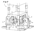
- Fig. 2
- den unteren Teil der Thermoformmaschine nach
Fig. 1 in perspektivischer Ansicht; - Fig. 3
- Kurvenverläufe für einige Systemparameter der Thermoformmaschine, aufgetragen über dem Drehweg der Kurbel des Bewegungselements; und
- Fig. 4
- in der Vorderansicht Schemadarstellungen des unteren Teils der Thermoformmaschine mit Betriebspositionen des unteren Werkzeugtisches in den Totpunktstellungen bei zwei aufeinander folgenden Arbeitszyklen.
- Fig. 1
- a thermoforming machine in front view;
- Fig. 2
- the lower part of the thermoforming machine
Fig. 1 in perspective view; - Fig. 3
- Curves for some system parameters of the thermoforming machine, plotted against the rotational path of the crank of the moving element; and
- Fig. 4
- in front view Schematic representations of the lower part of the thermoforming machine with operating positions of the lower tool table in the dead center positions in two successive working cycles.
In
Zur Bewegung der Werkzeugtische 4, 5 sind Bewegungselemente 6 vorgesehen, die wie folgt ausgebildet sind:For movement of the tool tables 4, 5
Spiegelbildlich zur Mittenebene 7 der Thermoformmaschine 1 sind sowohl zur Bewegung des Untertischs 4 als auch des Obertischs 5 je zwei Kniehebelsysteme 8 und 9 vorgesehen. Jedes Kniehebelsystem 8, 9 besteht - wie aus
Die Antriebsmotoren 10 werden jeweils so angesteuert, dass die beiden spiegelbildlich angeordneten Motoren gegensinnig zueinander drehen, wie in den
Die Drehbewegung bzw. das Drehmoment für die Kniehebel 12, 13 kann entweder über zwei einzelne Servo- oder Drehstrommotoren mit nachgeschalteten Getrieben erzeugt werden oder über jeweils nur ein Getriebe mit zwei Ausgängen und einem mittig am Getriebe angebauten Antriebsmotor 10. Schließlich ist auch ein Torquemotor einsetzbar, wodurch auf das Getriebe zwischen Motor 10 und Exzenter 19 verzichtet werden kann.The rotational movement or the torque for the toggle levers 12, 13 can be generated either via two individual servo or three-phase motors with downstream gearboxes or via only one gearbox with two outputs and a
Wie gesagt, sind die Drehrichtungen der Abtriebswellen bei den Einzelantrieben gegenläufig. Die Synchronisation der Drehbewegungen der beiderseits der Mittenebene 7 angeordneten Antriebsmotoren 10 kann dabei im so genannten "Master-Slave-Betrieb" erfolgen. Dabei wird über eine SPS-Maschinensteuerung und den an den Antriebsmotoren 10 befindlichen Inkremental- oder Absolutwertgebern der jeweils erforderliche Positionsabgleich beider Motoren 10 vorgenommen, was anhand der zur Verfügung stehenden elektronischen Mittel als solches vorbekannt ist (auch bekannt unter dem Begriff "elektronische Welle").As I said, the directions of rotation of the output shafts in the individual drives are in opposite directions. The synchronization of the rotational movements of both sides of the middle plane 7 arranged
In
Der Kurbeltrieb ist so ausgelegt, dass für jeden Arbeitszyklus die gleiche Drehrichtung beibehalten wird, wie durch
Bevor der untere Werkzeugtisch 4 die obere Totpunktlage gemäß b) erreicht, ist für die benötigte Formzeit (Abkühlung) mit Anstanzung der Folie ein erster Stopp des Kurbelantriebs eingelegt worden. Diesem schließt sich dann aber lediglich noch ein zweiter Stopp an, nämlich wenn sich nach dem beendeten ersten Arbeitszyklus der untere Werkzeugtisch 4 wie anfangs gemäß a) wieder in der unteren Totpunktlage befindet, was c) wiedergibt. Es setzt dann der vorbeschriebene Folgezyklus bzw. ein zweiter Arbeitszyklus ein, mit gegenüber dem vorhergehenden, ersten Arbeitszyklus aber wechselnder, unverändert jedoch gegensinniger Drehrichtung (vgl. die Pfeile 22a bzw. 22b in c) und d)) der Kurbelantriebe. Dieses Wechselspiel wiederholt sich fortlaufend während des Betriebs der Thermoformmaschine. Zu erwähnen ist in diesem Zusammenhang, daß die Kurbeln 11 stets zum Zeitpunkt des Ausstanzens der Folie, d.h. dann, wenn die Kniehebel 12, 13 ihre in den oberen Totpunkt-Endlagen gemäß b) und d) gestreckte Position einnehmen, mittig zu den beiden Kniehebeln 12, 13 verlaufen, somit rechtwinklig zu diesen stehen. Die unvermeidlichen, hohen Seitenkräfte F, wie in a) durch Pfeil angedeutet, werden dadurch aufgehoben.Before the lower tool table 4 reaches the top dead center position according to b), a first stop of the crank drive has been inserted for the required molding time (cooling) with punching of the film. However, this is then followed by only a second stop, namely when the lower tool table 4 is again in the lower dead center position as at the end of the first working cycle, as shown in a), which reproduces c). It then uses the above-described sequence cycle or a second duty cycle, with respect to the preceding, first cycle but changing, unchanged but opposite direction of rotation (see the
Es ist somit wichtig und festzuhalten, daß nach der beendeten Formzeit und dem erneuten Anfahren der Antriebsmotoren 10 zum Durchstanzen der Kunststofffolie 3 die Antriebe für das Werkzeugteil nicht erneut anhalten und mit Drehrichtungsänderung wieder zu ihrer Ausgangsposition zurückfahren. Vielmehr erreicht das jeweilige Werkzeugteil im oberen Totpunkt für den Untertisch 4 und im unteren Totpunkt für den Obertisch 5 seine Endposition, um mit gleicher Drehrichtung und hoher Drehzahl weiterzufahren. Nach dem Erreichen dieser Endlage, d. h. der weitesten entfernten Position von der Folie 3, wird der Antriebsmotor 10 zwecks Folientransport ohnehin angehalten. Wenn diese Bewegung abgeschlossen ist, drehen die Antriebsmotoren 10 ihre Drehrichtung um, um wiederum die Werkzeugtische 4, 5 auf die Folie 3 zu zu bewegen. Da die Kurbeltriebe für die stufenlos wählbaren Hübe der Werkzeugteile nicht um 360° drehend betrieben werden, sind die beiden Zyklen (s. mittig eingetragener Doppelpfeil in
Die erläuterte Thermoformmaschine hat mindestens eine Station und maximal drei Stationen, wobei jeweils zwei bewegliche Tische vorgesehen sind, die die jeweiligen Werkzeughälften aufnehmen, wobei diese je nach Verformungsrichtung der Artikel den entsprechenden Werkzeugtischhub stufenlos fahren müssen. Der Verfahrweg der Werkzeugteile kann ohne Umbaumaßnahmen stufenlos eingestellt werden.The illustrated thermoforming machine has at least one station and a maximum of three stations, wherein in each case two movable tables are provided, which receive the respective mold halves, which must drive the respective Werkzeugtischhub continuously depending on the deformation direction of the article. The travel of the tool parts can be adjusted continuously without modification.
Im Mittenbereich der vorgeschlagenen Thermoformmaschine verbleibt ein freier Bereich B (s.
Während bei vorbekannten Maschinen häufig eine maximale Taktzahl von nur 40 bis 70 Takte pro Minute erreichbar sind, sind mit dem vorgeschlagenen Konzept problemlos 85 Zyklen und mehr möglich.While in prior art machines often a maximum number of cycles of only 40 to 70 cycles per minute can be achieved, with the proposed concept easily 85 cycles and more possible.
- 11
- ThermoformmaschineThermoforming machine
- 22
- Artikelitems
- 33
- thermoplastische Kunststofffoliethermoplastic plastic film
- 44
- unterer Werkzeugtischlower tool table
- 55
- oberer Werkzeugtischupper tool table
- 66
- Bewegungselementmover
- 77
- Mittenebenemidplane
- 88th
- KniehebelsystemToggle system
- 99
- KniehebelsystemToggle system
- 1010
- Antriebsmotordrive motor
- 1111
- Kurbelcrank
- 1212
- Kniehebeltoggle
- 1313
- Kniehebeltoggle
- 1414
- Gehäusecasing
- 1515
- Maschinenständermachine stand
- 1616
- Führungssäuleguide column
- 1919
- Exzentereccentric
- 2020
- VorstreckerantriebPre-stretch drive
- 21a,b21a, b
- Drehrichtungspfeile (gegensinnig)Direction of rotation arrows (in opposite directions)
- 22a,b22a, b
- Drehrichtungspfeile (gegensinnigDirection of rotation arrows (in opposite directions
- 2323
- zweite Werkzeughälfte (Oberwerkzeug)second mold half (upper tool)
- 2424
- erste Werkzeughälfte (Unterwerkzeug)first tool half (lower tool)
- AA
- Öffnungs- und SchließrichtungOpening and closing direction
- BB
- freier Bereichfree area
- FF
- Seitenkraftlateral force
- II
- Hochfahrlinie (der unteren Werkzeughälfte)Start-up line (the lower half of the tool)
- IIII
- Herunterfahrlinie (der unteren Werkzeughälfte)Shut down line (the lower tool half)
Claims (9)
- A thermoforming machine (1) for forming and punching articles (2) out of a thermoplastic plastic sheet (3) that features a tool (23, 24) with at least two parts, with at least one of the tools (23, 24) that are respectively carried by a tool table (4, 5) being adjustable into an opening and closing direction (A) by means of a motion element (6), and with the motion element (6) consisting of two toggle lever systems (8, 9) that are arranged in the form of a mirror image referred to a central plane (7) of at least a section of the thermoforming machine (1),
characterized in
that the toggle lever systems (8, 9) can be respectively moved by a driving motor (10) via at least one crank (11), wherein the driving motors (10) are driven opposite to one another during each phase of motion, and wherein the driving motors with the cranks (11) are arranged on the side of the toggle lever system (8, 9) that faces away from the central plane (7) in such a way that a region (B) free of motion elements (6) results in the region of the central plane (7). - The thermoforming machine according to Claim 1,
characterized in
that the cranks (11) are coupled to the toggle lever systems (8, 9) on one side and to gear mechanisms (14) of the driving motors (10) on the other side in such a way that the cranks (11) only extend centrally referred to the toggle levers (12, 13) when the toggle lever systems (8, 9) are stretched. - The thermoforming machine according to Claim 1 or 2,
characterized in
that a lower tool table (4), as well as an upper tool table (5), is provided with a motion element (6). - The thermoforming machine according to one of Claims 1 to 3,
characterized in
that each toggle lever system (8, 9) consists of two toggle levers (12, 13) that are spaced apart from one another, wherein each toggle lever (12, 13) is connected to a crank (11). - The thermoforming machine according to one of Claims 1 to 4,
characterized in
that the driving motor (10) is arranged in or on a housing (14) together with the gear mechanism (14) and the bearing arrangement for the at least one crank (11). - The thermoforming machine according to one of Claims 1 to 5,
characterized in
that the angles of rotation of both driving motors (10) are motionally coupled. - The thermoforming machine according to Claim 6,
characterized in
that the coupling of the two driving motors (10) is realized with electronic means. - The thermoforming machine according to one of Claims 1 to 7,
characterized in
that the driving motors (10) consist of servomotors, torque motors or three-phase A.C. motors. - A method for operating a thermoforming machine (1) according to one of Claims 1 to 8 for forming and punching articles (2) out of a thermoplastic plastic sheet (3), with said thermoforming machine featuring a tool (23, 24) with at least two parts, with at least one of the tools (23, 24) that are respectively carried by a tool table (4, 5) being adjustable into an opening and closing direction (A) by means of a motion element (8), and with the motion element (6) consisting of two toggle lever systems (8, 9) that are arranged in the form of a mirror image referred to a central plane (7) of at least a section of the thermoforming machine (1), wherein crank mechanisms (10, 11, 19) acting upon the toggle lever systems (8, 9) are operated with angles of rotation that are adjusted differently in the individual motion cycles for opening and closing the tool tables (4, 5), but the motion cycles are divided into individual segments and the overall motion time is in total maintained constant by means of rotational speeds that deviate from one another in the individual segments.
Applications Claiming Priority (2)
| Application Number | Priority Date | Filing Date | Title |
|---|---|---|---|
| DE102006011039 | 2006-03-08 | ||
| DE102006019532A DE102006019532A1 (en) | 2006-03-08 | 2006-04-27 | Thermoforming machine |
Publications (3)
| Publication Number | Publication Date |
|---|---|
| EP1832408A2 EP1832408A2 (en) | 2007-09-12 |
| EP1832408A3 EP1832408A3 (en) | 2009-02-18 |
| EP1832408B1 true EP1832408B1 (en) | 2010-09-22 |
Family
ID=38162297
Family Applications (1)
| Application Number | Title | Priority Date | Filing Date |
|---|---|---|---|
| EP07004213A Not-in-force EP1832408B1 (en) | 2006-03-08 | 2007-03-01 | Thermoforming method and thermoforming machine with toggle mechanism |
Country Status (4)
| Country | Link |
|---|---|
| US (1) | US7510389B2 (en) |
| EP (1) | EP1832408B1 (en) |
| AT (1) | ATE482071T1 (en) |
| DE (2) | DE102006019532A1 (en) |
Families Citing this family (15)
| Publication number | Priority date | Publication date | Assignee | Title |
|---|---|---|---|---|
| JP2008043970A (en) * | 2006-08-14 | 2008-02-28 | Ihi Corp | Servo press, and operating method therefor |
| US8360273B2 (en) * | 2008-10-08 | 2013-01-29 | Dixie Consumer Products Llc | Cutlery utensil dispenser |
| US8356990B2 (en) * | 2009-05-01 | 2013-01-22 | Brian Keeley | Toggle drive system for driving in a thermoforming press |
| TW201200326A (en) * | 2010-03-29 | 2012-01-01 | Automation Tooling Syst | Mechanism and system for clamping |
| DE102010054976A1 (en) | 2010-06-07 | 2011-12-08 | Kiefel Gmbh | Thermoforming station, thermoforming machine, molding or stamping method, and manufactured articles |
| EP2666727B1 (en) * | 2012-05-24 | 2016-09-07 | MULTIVAC Sepp Haggenmüller SE & Co. KG | Lifting device for a packing machine |
| US10270709B2 (en) | 2015-06-26 | 2019-04-23 | Microsoft Technology Licensing, Llc | Allocating acceleration component functionality for supporting services |
| US9792154B2 (en) | 2015-04-17 | 2017-10-17 | Microsoft Technology Licensing, Llc | Data processing system having a hardware acceleration plane and a software plane |
| US10296392B2 (en) | 2015-04-17 | 2019-05-21 | Microsoft Technology Licensing, Llc | Implementing a multi-component service using plural hardware acceleration components |
| US10511478B2 (en) | 2015-04-17 | 2019-12-17 | Microsoft Technology Licensing, Llc | Changing between different roles at acceleration components |
| US10216555B2 (en) | 2015-06-26 | 2019-02-26 | Microsoft Technology Licensing, Llc | Partially reconfiguring acceleration components |
| WO2018035988A1 (en) * | 2016-08-25 | 2018-03-01 | 江苏贸隆机械制造有限公司 | Facial mask high speed cutting machine |
| DE112018005363A5 (en) * | 2017-09-21 | 2020-10-01 | Kiefel Gmbh | PUNCHING MACHINE, PUNCHING TOOL SETUP SYSTEM FOR A PUNCHING MACHINE, PUNCHING TOOLS, METHOD FOR SETTING UP A PUNCHING MACHINE, METHOD FOR SETTING UP A PUNCHING MACHINE, METHOD FOR OPERATING A PUNCHING STANKS |
| CN111098358A (en) * | 2019-12-25 | 2020-05-05 | 义乌融鹄电子科技有限公司 | Automatic blank mechanism of PC lens |
| CN112743892B (en) * | 2020-12-23 | 2021-08-27 | 无锡市欧凯电子有限公司 | Node righting point selection stamping control method and press |
Family Cites Families (13)
| Publication number | Priority date | Publication date | Assignee | Title |
|---|---|---|---|---|
| US2269758A (en) * | 1938-10-12 | 1942-01-13 | Noronha Rubber Products Corp D | Mechanical press |
| GB807760A (en) * | 1955-06-24 | 1959-01-21 | William Frank Golding | Improvements in or relating to power presses |
| NL285442A (en) * | 1961-11-13 | 1900-01-01 | ||
| US4158539A (en) * | 1978-05-10 | 1979-06-19 | Leesona Corporation | Thermoforming machine with variable mold closed cycle |
| US4608009A (en) * | 1984-05-23 | 1986-08-26 | John Brown Inc. | Thermoforming equipment for differential pressure forming products in thermoplastic material |
| US4588364A (en) * | 1985-04-01 | 1986-05-13 | Husky Injection Molding Systems Ltd. | Clamp mechanism |
| DE3604255A1 (en) | 1986-02-11 | 1987-08-13 | Illig Maschinenbau Adolf | Toggle-lever drive |
| JP2584287B2 (en) * | 1988-08-29 | 1997-02-26 | ファナック株式会社 | Toggle type mold clamping device |
| US5176923A (en) * | 1989-07-24 | 1993-01-05 | Ito Kogyo Kabushiki Kaisha | Mold-pressing apparatus incorporating electric servo motor and linking mechanism |
| DE19848628C2 (en) | 1998-10-22 | 2002-09-12 | Gabler Gmbh Maschbau | Method for operating a thermoforming machine |
| US6200122B1 (en) * | 1999-08-03 | 2001-03-13 | Brown Machine, Llc. | Thermoforming apparatus with improved press |
| US6477945B1 (en) * | 1999-09-07 | 2002-11-12 | Aida Engineering, Ltd. | Double-action mechanical press |
| AT414224B (en) * | 2002-07-19 | 2006-10-15 | Engel Austria Gmbh | Two plate injection molding machine with fixed and moveable platens useful for hydraulic systems of injection molding machines ensures favourable transfer ratio between clamping and driving forces of toggle lever systems |
-
2006
- 2006-04-27 DE DE102006019532A patent/DE102006019532A1/en not_active Withdrawn
-
2007
- 2007-03-01 AT AT07004213T patent/ATE482071T1/en active
- 2007-03-01 EP EP07004213A patent/EP1832408B1/en not_active Not-in-force
- 2007-03-01 DE DE502007005118T patent/DE502007005118D1/en active Active
- 2007-03-08 US US11/715,701 patent/US7510389B2/en not_active Expired - Fee Related
Also Published As
| Publication number | Publication date |
|---|---|
| US20070210487A1 (en) | 2007-09-13 |
| EP1832408A2 (en) | 2007-09-12 |
| US7510389B2 (en) | 2009-03-31 |
| EP1832408A3 (en) | 2009-02-18 |
| DE502007005118D1 (en) | 2010-11-04 |
| ATE482071T1 (en) | 2010-10-15 |
| DE102006019532A1 (en) | 2007-09-20 |
Similar Documents
| Publication | Publication Date | Title |
|---|---|---|
| EP1832408B1 (en) | Thermoforming method and thermoforming machine with toggle mechanism | |
| DE60214802T2 (en) | Method and tool closing unit for injection molding machines | |
| DE10325826A1 (en) | Device and method for driving a press | |
| WO2009156199A1 (en) | Direct drive for a compactor | |
| EP1497099B1 (en) | Thermoforming installation for producing shaped bodies made of plastic film, and method for producing the same | |
| WO2006045279A2 (en) | Drive system for a forming press | |
| EP3377311B1 (en) | Path-controlled press having a sliding block | |
| WO2004037527A2 (en) | Device for punching, stamping and/or shaping flat elements | |
| DE102009045543B4 (en) | Thermoforming system and drive unit and a method for operating the thermoforming system | |
| DE102012217276B4 (en) | Forging press and method for controlling this | |
| EP3209492B1 (en) | Press drive device for a press, and press comprising a press drive device | |
| DE102015117200B4 (en) | Embossing press and method for its operation | |
| DE10218511B4 (en) | Thermoforming plant for the production of moldings made of plastic film, and process for their preparation | |
| EP1981792B1 (en) | Apparatus for treating a material web | |
| EP2490886B1 (en) | Working method and assembly for operating presses | |
| DE19837632C2 (en) | upsetting press | |
| EP3584225A1 (en) | Method for controlling the rotary drive of a thermoforming machine | |
| DE10218486B4 (en) | Thermoforming plant for the production of moldings from plastic film, and process for their preparation | |
| EP2874793B1 (en) | Clamping unit for plastics injection moulding machine | |
| WO2011038921A1 (en) | Method for moving a machining unit of a machine | |
| EP3448594A1 (en) | Transfer press having a c-shaped ram | |
| DE19711759C2 (en) | Press device for the plastic deformation of materials, in particular thermoplastic plastic strips | |
| EP2529922A1 (en) | Drive device for a press, die cutter or moulding machine | |
| DE19839700A1 (en) | Method and device for closing and opening the tool of a plastics processing machine | |
| DE10253993A1 (en) | Folding machine for folding strip material with working rocker has gear elements between rotation motor, folding blade for translating defined motor rotation angle into constant tilting blade angle |
Legal Events
| Date | Code | Title | Description |
|---|---|---|---|
| PUAI | Public reference made under article 153(3) epc to a published international application that has entered the european phase |
Free format text: ORIGINAL CODE: 0009012 |
|
| AK | Designated contracting states |
Kind code of ref document: A2 Designated state(s): AT BE BG CH CY CZ DE DK EE ES FI FR GB GR HU IE IS IT LI LT LU LV MC MT NL PL PT RO SE SI SK TR |
|
| AX | Request for extension of the european patent |
Extension state: AL BA HR MK YU |
|
| PUAL | Search report despatched |
Free format text: ORIGINAL CODE: 0009013 |
|
| AK | Designated contracting states |
Kind code of ref document: A3 Designated state(s): AT BE BG CH CY CZ DE DK EE ES FI FR GB GR HU IE IS IT LI LT LU LV MC MT NL PL PT RO SE SI SK TR |
|
| AX | Request for extension of the european patent |
Extension state: AL BA HR MK RS |
|
| 17P | Request for examination filed |
Effective date: 20090801 |
|
| 17Q | First examination report despatched |
Effective date: 20090921 |
|
| AKX | Designation fees paid |
Designated state(s): AT BE BG CH CY CZ DE DK EE ES FI FR GB GR HU IE IS IT LI LT LU LV MC MT NL PL PT RO SE SI SK TR |
|
| GRAP | Despatch of communication of intention to grant a patent |
Free format text: ORIGINAL CODE: EPIDOSNIGR1 |
|
| RTI1 | Title (correction) |
Free format text: THERMOFORMING METHOD AND THERMOFORMING MACHINE WITH TOGGLE MECHANISM |
|
| GRAS | Grant fee paid |
Free format text: ORIGINAL CODE: EPIDOSNIGR3 |
|
| GRAA | (expected) grant |
Free format text: ORIGINAL CODE: 0009210 |
|
| AK | Designated contracting states |
Kind code of ref document: B1 Designated state(s): AT BE BG CH CY CZ DE DK EE ES FI FR GB GR HU IE IS IT LI LT LU LV MC MT NL PL PT RO SE SI SK TR |
|
| REG | Reference to a national code |
Ref country code: GB Ref legal event code: FG4D Free format text: NOT ENGLISH |
|
| REG | Reference to a national code |
Ref country code: CH Ref legal event code: EP |
|
| REG | Reference to a national code |
Ref country code: IE Ref legal event code: FG4D Free format text: LANGUAGE OF EP DOCUMENT: GERMAN |
|
| REF | Corresponds to: |
Ref document number: 502007005118 Country of ref document: DE Date of ref document: 20101104 Kind code of ref document: P |
|
| REG | Reference to a national code |
Ref country code: CH Ref legal event code: NV Representative=s name: SCHMAUDER & PARTNER AG PATENT- UND MARKENANWAELTE |
|
| PG25 | Lapsed in a contracting state [announced via postgrant information from national office to epo] |
Ref country code: LT Free format text: LAPSE BECAUSE OF FAILURE TO SUBMIT A TRANSLATION OF THE DESCRIPTION OR TO PAY THE FEE WITHIN THE PRESCRIBED TIME-LIMIT Effective date: 20100922 Ref country code: FI Free format text: LAPSE BECAUSE OF FAILURE TO SUBMIT A TRANSLATION OF THE DESCRIPTION OR TO PAY THE FEE WITHIN THE PRESCRIBED TIME-LIMIT Effective date: 20100922 |
|
| REG | Reference to a national code |
Ref country code: NL Ref legal event code: VDEP Effective date: 20100922 |
|
| LTIE | Lt: invalidation of european patent or patent extension |
Effective date: 20100922 |
|
| PG25 | Lapsed in a contracting state [announced via postgrant information from national office to epo] |
Ref country code: SI Free format text: LAPSE BECAUSE OF FAILURE TO SUBMIT A TRANSLATION OF THE DESCRIPTION OR TO PAY THE FEE WITHIN THE PRESCRIBED TIME-LIMIT Effective date: 20100922 Ref country code: PL Free format text: LAPSE BECAUSE OF FAILURE TO SUBMIT A TRANSLATION OF THE DESCRIPTION OR TO PAY THE FEE WITHIN THE PRESCRIBED TIME-LIMIT Effective date: 20100922 |
|
| PG25 | Lapsed in a contracting state [announced via postgrant information from national office to epo] |
Ref country code: SE Free format text: LAPSE BECAUSE OF FAILURE TO SUBMIT A TRANSLATION OF THE DESCRIPTION OR TO PAY THE FEE WITHIN THE PRESCRIBED TIME-LIMIT Effective date: 20100922 Ref country code: GR Free format text: LAPSE BECAUSE OF FAILURE TO SUBMIT A TRANSLATION OF THE DESCRIPTION OR TO PAY THE FEE WITHIN THE PRESCRIBED TIME-LIMIT Effective date: 20101223 Ref country code: LV Free format text: LAPSE BECAUSE OF FAILURE TO SUBMIT A TRANSLATION OF THE DESCRIPTION OR TO PAY THE FEE WITHIN THE PRESCRIBED TIME-LIMIT Effective date: 20100922 |
|
| REG | Reference to a national code |
Ref country code: IE Ref legal event code: FD4D |
|
| PG25 | Lapsed in a contracting state [announced via postgrant information from national office to epo] |
Ref country code: IE Free format text: LAPSE BECAUSE OF FAILURE TO SUBMIT A TRANSLATION OF THE DESCRIPTION OR TO PAY THE FEE WITHIN THE PRESCRIBED TIME-LIMIT Effective date: 20100922 |
|
| PG25 | Lapsed in a contracting state [announced via postgrant information from national office to epo] |
Ref country code: NL Free format text: LAPSE BECAUSE OF FAILURE TO SUBMIT A TRANSLATION OF THE DESCRIPTION OR TO PAY THE FEE WITHIN THE PRESCRIBED TIME-LIMIT Effective date: 20100922 Ref country code: EE Free format text: LAPSE BECAUSE OF FAILURE TO SUBMIT A TRANSLATION OF THE DESCRIPTION OR TO PAY THE FEE WITHIN THE PRESCRIBED TIME-LIMIT Effective date: 20100922 Ref country code: RO Free format text: LAPSE BECAUSE OF FAILURE TO SUBMIT A TRANSLATION OF THE DESCRIPTION OR TO PAY THE FEE WITHIN THE PRESCRIBED TIME-LIMIT Effective date: 20100922 Ref country code: PT Free format text: LAPSE BECAUSE OF FAILURE TO SUBMIT A TRANSLATION OF THE DESCRIPTION OR TO PAY THE FEE WITHIN THE PRESCRIBED TIME-LIMIT Effective date: 20110124 Ref country code: SK Free format text: LAPSE BECAUSE OF FAILURE TO SUBMIT A TRANSLATION OF THE DESCRIPTION OR TO PAY THE FEE WITHIN THE PRESCRIBED TIME-LIMIT Effective date: 20100922 Ref country code: IS Free format text: LAPSE BECAUSE OF FAILURE TO SUBMIT A TRANSLATION OF THE DESCRIPTION OR TO PAY THE FEE WITHIN THE PRESCRIBED TIME-LIMIT Effective date: 20110122 Ref country code: CZ Free format text: LAPSE BECAUSE OF FAILURE TO SUBMIT A TRANSLATION OF THE DESCRIPTION OR TO PAY THE FEE WITHIN THE PRESCRIBED TIME-LIMIT Effective date: 20100922 |
|
| PG25 | Lapsed in a contracting state [announced via postgrant information from national office to epo] |
Ref country code: ES Free format text: LAPSE BECAUSE OF FAILURE TO SUBMIT A TRANSLATION OF THE DESCRIPTION OR TO PAY THE FEE WITHIN THE PRESCRIBED TIME-LIMIT Effective date: 20110102 |
|
| PLBE | No opposition filed within time limit |
Free format text: ORIGINAL CODE: 0009261 |
|
| STAA | Information on the status of an ep patent application or granted ep patent |
Free format text: STATUS: NO OPPOSITION FILED WITHIN TIME LIMIT |
|
| 26N | No opposition filed |
Effective date: 20110623 |
|
| PG25 | Lapsed in a contracting state [announced via postgrant information from national office to epo] |
Ref country code: DK Free format text: LAPSE BECAUSE OF FAILURE TO SUBMIT A TRANSLATION OF THE DESCRIPTION OR TO PAY THE FEE WITHIN THE PRESCRIBED TIME-LIMIT Effective date: 20100922 |
|
| BERE | Be: lapsed |
Owner name: GABLER THERMOFORM G.M.B.H. & CO. KG Effective date: 20110331 |
|
| REG | Reference to a national code |
Ref country code: DE Ref legal event code: R097 Ref document number: 502007005118 Country of ref document: DE Effective date: 20110623 |
|
| PG25 | Lapsed in a contracting state [announced via postgrant information from national office to epo] |
Ref country code: MC Free format text: LAPSE BECAUSE OF NON-PAYMENT OF DUE FEES Effective date: 20110331 |
|
| GBPC | Gb: european patent ceased through non-payment of renewal fee |
Effective date: 20110301 |
|
| REG | Reference to a national code |
Ref country code: FR Ref legal event code: ST Effective date: 20111130 |
|
| PG25 | Lapsed in a contracting state [announced via postgrant information from national office to epo] |
Ref country code: MT Free format text: LAPSE BECAUSE OF FAILURE TO SUBMIT A TRANSLATION OF THE DESCRIPTION OR TO PAY THE FEE WITHIN THE PRESCRIBED TIME-LIMIT Effective date: 20100922 Ref country code: BE Free format text: LAPSE BECAUSE OF NON-PAYMENT OF DUE FEES Effective date: 20110331 |
|
| PG25 | Lapsed in a contracting state [announced via postgrant information from national office to epo] |
Ref country code: FR Free format text: LAPSE BECAUSE OF NON-PAYMENT OF DUE FEES Effective date: 20110331 |
|
| PG25 | Lapsed in a contracting state [announced via postgrant information from national office to epo] |
Ref country code: GB Free format text: LAPSE BECAUSE OF NON-PAYMENT OF DUE FEES Effective date: 20110301 |
|
| REG | Reference to a national code |
Ref country code: AT Ref legal event code: MM01 Ref document number: 482071 Country of ref document: AT Kind code of ref document: T Effective date: 20120301 |
|
| PG25 | Lapsed in a contracting state [announced via postgrant information from national office to epo] |
Ref country code: LU Free format text: LAPSE BECAUSE OF NON-PAYMENT OF DUE FEES Effective date: 20110301 Ref country code: CY Free format text: LAPSE BECAUSE OF FAILURE TO SUBMIT A TRANSLATION OF THE DESCRIPTION OR TO PAY THE FEE WITHIN THE PRESCRIBED TIME-LIMIT Effective date: 20100922 |
|
| PG25 | Lapsed in a contracting state [announced via postgrant information from national office to epo] |
Ref country code: AT Free format text: LAPSE BECAUSE OF NON-PAYMENT OF DUE FEES Effective date: 20120301 |
|
| PG25 | Lapsed in a contracting state [announced via postgrant information from national office to epo] |
Ref country code: BG Free format text: LAPSE BECAUSE OF FAILURE TO SUBMIT A TRANSLATION OF THE DESCRIPTION OR TO PAY THE FEE WITHIN THE PRESCRIBED TIME-LIMIT Effective date: 20101222 Ref country code: TR Free format text: LAPSE BECAUSE OF FAILURE TO SUBMIT A TRANSLATION OF THE DESCRIPTION OR TO PAY THE FEE WITHIN THE PRESCRIBED TIME-LIMIT Effective date: 20100922 |
|
| PG25 | Lapsed in a contracting state [announced via postgrant information from national office to epo] |
Ref country code: HU Free format text: LAPSE BECAUSE OF FAILURE TO SUBMIT A TRANSLATION OF THE DESCRIPTION OR TO PAY THE FEE WITHIN THE PRESCRIBED TIME-LIMIT Effective date: 20100922 |
|
| PGFP | Annual fee paid to national office [announced via postgrant information from national office to epo] |
Ref country code: CH Payment date: 20190320 Year of fee payment: 13 Ref country code: IT Payment date: 20190325 Year of fee payment: 13 Ref country code: DE Payment date: 20190321 Year of fee payment: 13 |
|
| PGFP | Annual fee paid to national office [announced via postgrant information from national office to epo] |
Ref country code: DE Payment date: 20190321 Year of fee payment: 13 |
|
| REG | Reference to a national code |
Ref country code: DE Ref legal event code: R119 Ref document number: 502007005118 Country of ref document: DE |
|
| REG | Reference to a national code |
Ref country code: CH Ref legal event code: PL |
|
| PG25 | Lapsed in a contracting state [announced via postgrant information from national office to epo] |
Ref country code: CH Free format text: LAPSE BECAUSE OF NON-PAYMENT OF DUE FEES Effective date: 20200331 Ref country code: DE Free format text: LAPSE BECAUSE OF NON-PAYMENT OF DUE FEES Effective date: 20201001 Ref country code: LI Free format text: LAPSE BECAUSE OF NON-PAYMENT OF DUE FEES Effective date: 20200331 |
|
| PG25 | Lapsed in a contracting state [announced via postgrant information from national office to epo] |
Ref country code: IT Free format text: LAPSE BECAUSE OF NON-PAYMENT OF DUE FEES Effective date: 20200301 |