EP1832016B1 - Optically connecting computer components - Google Patents
Optically connecting computer components Download PDFInfo
- Publication number
- EP1832016B1 EP1832016B1 EP05855837A EP05855837A EP1832016B1 EP 1832016 B1 EP1832016 B1 EP 1832016B1 EP 05855837 A EP05855837 A EP 05855837A EP 05855837 A EP05855837 A EP 05855837A EP 1832016 B1 EP1832016 B1 EP 1832016B1
- Authority
- EP
- European Patent Office
- Prior art keywords
- optical
- component
- socket
- plug
- optically
- Prior art date
- Legal status (The legal status is an assumption and is not a legal conclusion. Google has not performed a legal analysis and makes no representation as to the accuracy of the status listed.)
- Expired - Lifetime
Links
Images


Classifications
-
- H—ELECTRICITY
- H04—ELECTRIC COMMUNICATION TECHNIQUE
- H04B—TRANSMISSION
- H04B10/00—Transmission systems employing electromagnetic waves other than radio-waves, e.g. infrared, visible or ultraviolet light, or employing corpuscular radiation, e.g. quantum communication
- H04B10/80—Optical aspects relating to the use of optical transmission for specific applications, not provided for in groups H04B10/03 - H04B10/70, e.g. optical power feeding or optical transmission through water
- H04B10/801—Optical aspects relating to the use of optical transmission for specific applications, not provided for in groups H04B10/03 - H04B10/70, e.g. optical power feeding or optical transmission through water using optical interconnects, e.g. light coupled isolators, circuit board interconnections
Definitions
- Portable processor-based systems including laptop computers (laptops), also termed notebook computers, and hand held computers such as personal digital assistants (PDAs) or "smart" mobile telephones (devices integrating PDA and mobile phone functionality) are popular.
- PDAs personal digital assistants
- Such devices are sometimes designed to trade off capability for portability, for example, a laptop computer may not include an integrated CD or DVD reader, but allow connection to one using a cable connector of an external bus, or via a docking station or a port replicator.
- a laptop display is generally small in size and may be limited in brightness and resolution, but the laptop may be connected to an external display using for example a Digital Video Interface (DVI) connector, as specified in the DYI 1.0 Specification available from the Digital Display Working Group (DDWG) or Video Graphics Array (VGA) connector, well known in the art, on the laptop and a video signal cable.
- DVI Digital Video Interface
- DDWG Digital Display Working Group
- VGA Video Graphics Array
- a docking station is a device that mechanically and electrically couples with a laptop to provide additional functionality, including, for example, additional external ports and drives for removable media. Docking stations may also be referred to as port replicators; alternatively, the term port replicator may also be used to refer to a docking station with limited functionality.
- a PDA or smart phone may come with no hardware keyboard, but may be connected to one using a cable connector of an external bus or a docking station designed for the PDA or smart phone.
- Cable connection to external peripherals for a laptop is limited because such cables are limited in length by the physical parameters of their construction and the nature of the signals they carry, especially for cables that carry high bandwidth signals such as video or high speed data such as that specified in the Universal Serial Bus Revision 2.0 Specification (USB 2.0) available from the USB Implementers Forum or that specified in the several IEEE 1394 specifications available from the 1394 Trade Association cables (FireWire). Docking stations are often expensive because they require connectivity to a system bus of the laptop or hand held computer and may have large, multi-pin electrical connectors that are complex and use expensive precision-manufactured parts.
- US 6,502,997 discusses an optical fiber connector and cable having a transducer and a receiver for optical transmission.
- US 2003/0113078 discusses a multi-component optical package and optical fiber coupled to create an optical data interface for communication of data between data systems.
- WO 93/08654 discusses a system of wireless transmitting and receiving devices which communicate using infrared signals.
- the first component, 105 is a central or base component and includes a processor of the system.
- the component 105 may be the "CPU" unit of a personal computer (PC) that includes the mainboard; it may in other embodiments be a laptop, or a server computer, or another component in a processor-based system that contains a processor of the system.
- This component communicates with an external peripheral component 145 using optical data transmitted from the central component and received at 125 by the peripheral or transmitted from the peripheral and received by the central component, 120.
- the transmission may be over one or more optical fibers comprising an optical cable in some embodiments, or over another waveguide, or via any optical path through an optically transmissive medium such as air, vacuum, or glass in other embodiments.
- the data 120 and 125 may travel via fiber or another optical waveguide along part of its transmission and along another type of waveguide or another optical path such as through air, vacuum, or glass along another part of its transmission.
- components 105 and 145 may also separately be connected by other means such as by electrical or radio frequency links.
- each of the components has means for interfacing with the optical data transmitted and received by the component.
- the central component has an optical transceiver 115 and the peripheral component has a separate optical receiver 130 and a separate optical transmitter 135.
- the central component may have a separate transmitter and receiver and the peripheral may have a transceiver; or both components may have transceivers; or both components may have separate transmitters and receivers.
- one pair of optical communication paths is shown in the figure, in other components there may be a plurality of optical connections or optically implemented communication channels between the two components in other embodiments.
- the two components may be connected by a path for optical data traveling in only one direction, i.e. with only a transmitter on one component and only a receiver on the other.
- many other configurations are possible.
- An optical transmitter receiver pair such as that referenced above is depicted in figure 2 .
- An optical transmitter 210 may be a laser emitter, implemented in some embodiments as a vertical cavity surface emitting laser (VCSEL), or alternatively in some embodiments a light emitting diode (LED) capable of being switched at a high frequency implemented as part of a circuit.
- An optical receiver may include for one instance a p-i-n or PIN diode or in another instance an Avalanche Photo Diode (APD) detector component and circuit and further a trans-impedance amplifer/post amplifier (TIA/Post-amp) circuit as at 230 in fig. 2 in some embodiments.
- the transmitter and receiver are shown connected by an optical fiber 220 in the figure.
- other media, and combinations of fiber and other media, including an optical path through a optically transmissive medium may also be used between the optical transmitter and optical receiver in some embodiments.
- an optical transmitter and receiver may be integrated into a single circuit or integrated circuit as shown abstractly in fig. 3 , to form optical transceivers 310.
- the circuit may contain a laser emitter such as a VCSEL or Fabry-Perot laser, or an LED emitter, and a detector or receiver such as a PIN diode and associated sub-circuits such as a TIA/Post-amp circuit.
- the transceivers are shown connected by optical fiber 320 in the figure. Again, other media and combinations of fiber and other media including an optical path through a optically transmissive medium may also be used between the optical transmitter and optical receiver in some embodiments.
- the fiber When an optical fiber is used to transmit optically encoded data between a transmitter and a receiver or between transceivers as in figures 2 and 3 , the fiber, as shown in Figure 4 at 430, is integrated into a cable assembly which may have at each end a plug 420. As depicted in the figure, plug 420 may mate with a socket 410, allowing for an optical coupling of optical data traveling between the socket and the fiber, and between the fiber and the socket. In the figure, an embodiment is shown with a plug and socket arrangement at each end. Of course, the plug may either be a "male” or “female” plug, and similarly the corresponding socket may be either a "female” or “male” socket in different embodiments as is known in the art. In other embodiments, one of the ends of the fiber may be integrated directly into a device without an intervening plug and socket arrangement.
- the plug and socket 420 and 410 of fig. 4 may implement an optical transceiver as previously described with reference to in fig.3 in some embodiments, or an optical transmitter or receiver as previously described with reference to fig. 2 in others. If an optical fiber 430 has a plug and socket at each end, the plug and socket at one end is functionally related to the other. Thus, if the plug and socket combination 420 and 410 at one end of the fiber forms a transceiver, then the other plug and socket combination at the distal end is also a transceiver. If one plug and socket pair forms a transmitter, the other plug and socket pair must be a receiver.
- the plug and socket 420 and 410 are implemented as a VCSEL plastic optical link (VPOL) plug and socket, formed by a molded lead frame, including a metal lead frame and a molded precision plastic component comprising a waveguiding and lensing assembly, for example, a mirror and lens assembly and an integrated circuit providing VCSEL functionality, the detector sensor, and the detector circuit.
- VPOL VCSEL plastic optical link
- the plug and socket 420 and 410 may each be connected to a device and provide for direct optical transmission from one device to another through air or vacuum, without an optical fiber or other waveguide intervening.
- a docking connector for a laptop docking station may be implemented by a plug and socket arrangement similar to the arrangement shown in fig. 4 .
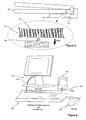
- a laptop 505 is shown with a docking station 510.
- the optical plug and socket may in one embodiment be constructed as shown at 520 and 530, with the plug integrated into the base of the laptop 525 and the socket integrated into the mating surface of the docking station at 530.
- the optical transceivers in the plug 530 and 520 may align and communicate optically through the air and allow data communication between the laptop 505 and docking station 510.
- the plug and socket arrangement to couple the laptop and docking station may include an intermediate waveguide such as an optical fiber.
- a PDA 605 may be connected to a docking system.
- the docking system may include a keyboard portion 620 and a monitor output to connect via connector 615 an external monitor 610 and a mouse 625 to the docking system.
- Such a system may provide compact connectivity between the PDA and the docking system using an optical connector 607.
- This connector may be an optical fiber cable or other waveguide with plug connectors at both ends such as that described in fig. 4 and with corresponding sockets in the docking unit 620 and PDA 605. Alternately, it may be an optical fiber cable integrated into the docking station with a plug at one end and a corresponding socket in the PDA.
- embodiments may be part of a general processor based system 700.
- the system shown includes a processor 705, a bus 712 communicatively coupling the processor to a memory 710 and other internal storage 715 such as a hard drive.
- a system may be a desktop PC, laptop, server computer, other computer, a personal digital assistant, smartphone, entertainment device such as a game console, or another processor based device.
- the device is connectible to external peripherals 720, 725, and 730, which may be one or more of several types of devices.
- peripheral device connectible to the system may be a mass storage device 720 which may be, for example, a disk drive such as a CD or DVD storage drive, a hard disk drive, a non-volatile memory store such as a flash memory based storage device, among many others, as is known in the art.
- a peripheral may be a display device 725 such as a cathode ray tube (CRT) or liquid crystal display (LCD) or one of many other displays, as is known in the art.
- CTR cathode ray tube
- LCD liquid crystal display
- Many other peripherals 730 are similarly connectible to the system, for example, printers, plotters scanners, cameras, audio devices, and many more.
- a graphics processing unit may be used to process data from the system 700 for display.
- the interconnects 735 between the base component of the system 740 and the external peripherals may each be implemented as an optical data link in this embodiment, each of which may be an optical connector such as the ones described above.
- the interconnects 735 may additionally carry electrical power and electronic data over one or more wires.
- the links 735 may be optical fiber based cables with a plug and socket connector at one or either end; or docking connectors with plug and socket connectors that allow a peripheral to directly mechanically and optically mate with the system in others.
- many variations of the internal components, organization and peripherals shown in fig. 7 are possible in differing embodiments.
- a design of an embodiment may go through various stages, from creation to simulation to fabrication.
- Data representing a design may represent the design in a number of manners.
- the hardware may be represented using a hardware description language or another functional description language.
- a circuit level model with logic and/or transistor gates may be produced at some stages of the design process.
- most designs, at some stage reach a level of data representing the physical placement of various devices in the hardware model.
- data representing a hardware model may be the data specifying the presence or absence of various features on different mask layers for masks used to produce the integrated circuit.
- the data may be stored in any form of a machine-readable medium.
- An optical or electrical wave modulated or otherwise generated to transmit such information, a memory, or a magnetic or optical storage such as a disc may be the machine readable medium. Any of these mediums may "carry” or “indicate” the design or software information.
- an electrical carrier wave indicating or carrying the code or design is transmitted, to the extent that copying, buffering, or re-transmission of the electrical signal is performed, a new copy is made.
- a communication provider or a network provider may make copies of an article (a carrier wave) that constitute or represent an embodiment.
- Embodiments may be provided at least in part as a program product that may include a machine-readable medium having stored thereon data which when accessed by a machine may cause the machine to perform a process according to the claimed subject matter.
- the machine-readable medium may include, but is not limited to, floppy diskettes, optical disks, DVD-ROM disks, DVD-RAM disks, DVD-RW disks, DVD+RW disks, CD-R disks, CD-RW disks, CD-ROM disks, and magneto-optical disks, ROMs, RAMs, EPROMs, EEPROMs, magnet or optical cards, FLASH memory, or other type of media / machine-readable medium suitable for storing electronic instructions.
- embodiments may also be downloaded as a program product, wherein the program may be transferred from a remote data source to a requesting device by way of data signals embodied in a carrier wave or other propagation medium via a communication link (e.g., a modem or network connection).
- a communication link e.g., a modem or network connection
Landscapes
- Physics & Mathematics (AREA)
- Electromagnetism (AREA)
- Engineering & Computer Science (AREA)
- Computer Networks & Wireless Communication (AREA)
- Signal Processing (AREA)
- Optical Couplings Of Light Guides (AREA)
- Optical Communication System (AREA)
Applications Claiming Priority (2)
| Application Number | Priority Date | Filing Date | Title |
|---|---|---|---|
| US11/026,667 US7881614B2 (en) | 2004-12-31 | 2004-12-31 | Optically connecting computer components |
| PCT/US2005/047342 WO2006074030A1 (en) | 2004-12-31 | 2005-12-28 | Optically connecting computer components |
Publications (2)
| Publication Number | Publication Date |
|---|---|
| EP1832016A1 EP1832016A1 (en) | 2007-09-12 |
| EP1832016B1 true EP1832016B1 (en) | 2013-02-27 |
Family
ID=36177780
Family Applications (1)
| Application Number | Title | Priority Date | Filing Date |
|---|---|---|---|
| EP05855837A Expired - Lifetime EP1832016B1 (en) | 2004-12-31 | 2005-12-28 | Optically connecting computer components |
Country Status (4)
| Country | Link |
|---|---|
| US (1) | US7881614B2 (enExample) |
| EP (1) | EP1832016B1 (enExample) |
| JP (1) | JP2008525922A (enExample) |
| WO (1) | WO2006074030A1 (enExample) |
Families Citing this family (18)
| Publication number | Priority date | Publication date | Assignee | Title |
|---|---|---|---|---|
| US7575380B2 (en) * | 2004-10-15 | 2009-08-18 | Emcore Corporation | Integrated optical fiber and electro-optical converter |
| US20070269219A1 (en) * | 2006-05-19 | 2007-11-22 | Teller Witold R | System and apparatus for optical communications through a semi-opaque material |
| US8059006B2 (en) * | 2007-05-18 | 2011-11-15 | Schweitzer Engineering Laboratories, Inc. | System and method for communicating power system information through a radio frequency device |
| US7371014B2 (en) * | 2006-08-21 | 2008-05-13 | Intel Corporation | Monolithic active optical cable assembly for data device applications and various connector types |
| US7578623B2 (en) | 2006-08-21 | 2009-08-25 | Intel Corporation | Aligning lens carriers and ferrules with alignment frames |
| US8769171B2 (en) * | 2007-04-06 | 2014-07-01 | Finisar Corporation | Electrical device with electrical interface that is compatible with integrated optical cable receptacle |
| WO2010040816A2 (de) * | 2008-10-09 | 2010-04-15 | Silicon Line Gmbh | Schaltungsanordnung und verfahren zum übertragen von tmds-kodierten signalen |
| US7890688B2 (en) * | 2008-12-08 | 2011-02-15 | Avago Technologies Fiber Ip (Singapore) Pte. Ltd. | Method and apparatus for providing a high-speed communications link between a portable device and a docking station |
| KR101316596B1 (ko) | 2009-06-15 | 2013-10-15 | 트시와네 유니버시티 오브 테크놀로지 | 엠오디-이 애밸런치 엘이디들을 사용하는 올 실리콘 750 나노미터 및 시모스 기반 광통신 시스템 |
| US8224383B2 (en) * | 2009-12-04 | 2012-07-17 | Musa Mawanda | Extensible mobile computing platform |
| TWI580204B (zh) * | 2012-05-02 | 2017-04-21 | 鴻海精密工業股份有限公司 | 數據傳輸系統及其光纖數據線 |
| JP6231954B2 (ja) * | 2014-07-23 | 2017-11-15 | 株式会社フジクラ | 画像送受信システム、アクティブケーブルの監視方法、アクティブケーブルの制御方法、画像送信装置、画像受信装置、及びアクティブケーブル |
| US11768545B2 (en) | 2017-04-05 | 2023-09-26 | Fibernet Ltd. | Secured KVM switching device with unidirectional communications |
| US10348415B2 (en) * | 2017-05-30 | 2019-07-09 | Honeywell International Inc. | Optical wireless communications for vehicle operator personal computing devices |
| IL265789B2 (en) | 2019-04-02 | 2025-04-01 | Fibernet Ltd | Secure video streaming device |
| IL266118B2 (en) | 2019-04-17 | 2023-08-01 | Fibernet Ltd | Device for secure streaming of audio |
| EP4193206A4 (en) * | 2020-08-04 | 2024-07-31 | Avicenatech Corp. | IMPROVED MICRO-LEDS FOR INTER-CHIP COMMUNICATION |
| CN119310763A (zh) * | 2023-07-12 | 2025-01-14 | 纬联电子科技(中山)有限公司 | 显示器设备及其显示器承载装置 |
Family Cites Families (28)
| Publication number | Priority date | Publication date | Assignee | Title |
|---|---|---|---|---|
| US5184314A (en) * | 1991-07-31 | 1993-02-02 | Kelly Edward J | Mobile data processing and communcations system with removable portable computer |
| WO1993008654A1 (en) | 1991-10-18 | 1993-04-29 | Forte Communications, Inc. | Wireless transmitting and receiving device with selectable channel settings |
| JPH07210644A (ja) | 1994-01-11 | 1995-08-11 | I T T Canon:Kk | 光通信カードユニット |
| US6446867B1 (en) * | 1995-11-22 | 2002-09-10 | Jorge Sanchez | Electro-optic interface system and method of operation |
| US5864708A (en) * | 1996-05-20 | 1999-01-26 | Croft; Daniel I. | Docking station for docking a portable computer with a wireless interface |
| US5877882A (en) * | 1996-06-13 | 1999-03-02 | International Business Machines Corp. | Optical docking station |
| JPH1166732A (ja) * | 1997-08-13 | 1999-03-09 | Sony Corp | データ伝送装置 |
| US6236486B1 (en) * | 1997-12-05 | 2001-05-22 | Intermec Ip Corp. | Data communication system for printer and handheld computer |
| EP0977063A1 (en) | 1998-07-28 | 2000-02-02 | Interuniversitair Micro-Elektronica Centrum Vzw | A socket and a system for optoelectronic interconnection and a method of fabricating such socket and system |
| JP2000163171A (ja) | 1998-11-24 | 2000-06-16 | Sharp Corp | 携帯端末とドッキングステーションとの間の通信制御方法およびドッキングステーションに装着可能な携帯端末 |
| KR100652355B1 (ko) | 1999-03-10 | 2006-11-30 | 삼성전자주식회사 | 광전송을 위한 송수신기를 내장한 커넥터 및 케이블 |
| KR100477637B1 (ko) * | 1999-11-10 | 2005-03-23 | 삼성전자주식회사 | 컴퓨터의 도킹 시스템 |
| KR100462591B1 (ko) * | 1999-11-10 | 2004-12-20 | 삼성전자주식회사 | 휴대형 컴퓨터의 도킹 시스템 |
| US6344911B1 (en) | 1999-12-29 | 2002-02-05 | Corning Incorporated | Upgradable optical communication system module |
| US6913400B2 (en) * | 2000-11-03 | 2005-07-05 | Tyco Electronics Corporation | Optoelectric module for multi-fiber arrays |
| KR100402409B1 (ko) | 2001-05-26 | 2003-10-30 | (주)오피트정보통신 | 원거리 전송이 가능한 디지털 비디오 신호 인터페이스 모듈 |
| US20030113078A1 (en) | 2001-12-13 | 2003-06-19 | Tatum Jimmy A. | Methods, systems and means for providing data communications between data equipment |
| US6739766B2 (en) * | 2001-12-17 | 2004-05-25 | Stratos International, Inc. | Lens array for use in parallel optics modules for fiber optics communications |
| US6729771B2 (en) * | 2001-12-17 | 2004-05-04 | Stratos Lightwave, Inc. | Parallel optics subassembly having at least twelve lenses |
| US7028128B2 (en) | 2002-01-30 | 2006-04-11 | Hewlett-Packard Development Company, L.P. | Port replication in an electronic device that allows for a single network controller |
| US7269357B2 (en) | 2002-08-02 | 2007-09-11 | Finisar Corporation | Transceiver with programmable signal parameters |
| JP4712557B2 (ja) | 2002-08-02 | 2011-06-29 | フィニサー コーポレイション | プログラム可能な信号パラメータを備えた送受信器 |
| US6943755B1 (en) * | 2002-10-07 | 2005-09-13 | Analog Devices, Inc. | Card-enabled, head-wearable secondary display systems |
| US20040066620A1 (en) * | 2002-10-08 | 2004-04-08 | Dell Products L.P. | Device to allow computers to adapt to multiple docking stations |
| US20040120720A1 (en) * | 2002-12-24 | 2004-06-24 | Chang Chin L. | Fiber optic transceiver with VCSEL source |
| US7653315B2 (en) * | 2003-01-21 | 2010-01-26 | Gateway, Inc. | Bi-directional optical monitor interconnect |
| JP2004288674A (ja) | 2003-03-19 | 2004-10-14 | Fuji Xerox Co Ltd | 面発光型半導体レーザおよびそれを用いた光通信システム |
| US20040263941A1 (en) * | 2003-06-24 | 2004-12-30 | Chung-Chien Chen | Single fiber connector extension for transmission of digital video data |
-
2004
- 2004-12-31 US US11/026,667 patent/US7881614B2/en not_active Expired - Fee Related
-
2005
- 2005-12-28 WO PCT/US2005/047342 patent/WO2006074030A1/en not_active Ceased
- 2005-12-28 JP JP2007549609A patent/JP2008525922A/ja active Pending
- 2005-12-28 EP EP05855837A patent/EP1832016B1/en not_active Expired - Lifetime
Also Published As
| Publication number | Publication date |
|---|---|
| WO2006074030A1 (en) | 2006-07-13 |
| US7881614B2 (en) | 2011-02-01 |
| EP1832016A1 (en) | 2007-09-12 |
| JP2008525922A (ja) | 2008-07-17 |
| US20060147214A1 (en) | 2006-07-06 |
Similar Documents
| Publication | Publication Date | Title |
|---|---|---|
| EP1832016B1 (en) | Optically connecting computer components | |
| KR101287247B1 (ko) | 정렬 범프 및 노치를 사용한 커넥터 정렬 | |
| CN102045112B (zh) | 光学通用串行总线装置及其操作方法 | |
| US8543751B2 (en) | Computer card | |
| US8989588B2 (en) | Optical transceiver with equalization and controllable laser interconnection interface | |
| US9660364B2 (en) | System interconnect for integrated circuits | |
| CN101268395B (zh) | 模块化光学设备管壳 | |
| CN105182484B (zh) | 光学缆线模块及其制造方法 | |
| TWI502235B (zh) | 具有平面對準和固定之光學收發器介面 | |
| US20130343698A1 (en) | Ir reflowable optical transceiver | |
| US12153267B2 (en) | Optical module | |
| US10903913B2 (en) | Free air optical interconnect attach mechanism | |
| US20060031611A1 (en) | Digital video signal interface module | |
| TW201323956A (zh) | 具有c型平面對準及固定特徵的光學收發器介面 | |
| EP2116879B1 (en) | Optical interface | |
| US10148365B2 (en) | Hybrid free air and electrical interconnect | |
| JP2008525922A5 (enExample) | ||
| US10756824B2 (en) | Free air optical backplane interconnect | |
| US10516490B2 (en) | Optical free air transmit and receive interconnect | |
| CN112041718B (zh) | 光通信连接器、光发射器、光接收器、光通信系统和光通信线缆 | |
| CN101432676A (zh) | 计算装置天线识别系统和方法 | |
| TW201544861A (zh) | 光學纜線模組及其製造方法 | |
| CN218675388U (zh) | 一种光模块 | |
| TW201216575A (en) | Support structure of display apparatus | |
| US10700790B2 (en) | Optical driver circuitry for burst mode transfer |
Legal Events
| Date | Code | Title | Description |
|---|---|---|---|
| PUAI | Public reference made under article 153(3) epc to a published international application that has entered the european phase |
Free format text: ORIGINAL CODE: 0009012 |
|
| 17P | Request for examination filed |
Effective date: 20070629 |
|
| AK | Designated contracting states |
Kind code of ref document: A1 Designated state(s): AT BE BG CH CY CZ DE DK EE ES FI FR GB GR HU IE IS IT LI LT LU LV MC NL PL PT RO SE SI SK TR |
|
| DAX | Request for extension of the european patent (deleted) | ||
| 17Q | First examination report despatched |
Effective date: 20090226 |
|
| GRAP | Despatch of communication of intention to grant a patent |
Free format text: ORIGINAL CODE: EPIDOSNIGR1 |
|
| GRAS | Grant fee paid |
Free format text: ORIGINAL CODE: EPIDOSNIGR3 |
|
| GRAA | (expected) grant |
Free format text: ORIGINAL CODE: 0009210 |
|
| AK | Designated contracting states |
Kind code of ref document: B1 Designated state(s): AT BE BG CH CY CZ DE DK EE ES FI FR GB GR HU IE IS IT LI LT LU LV MC NL PL PT RO SE SI SK TR |
|
| REG | Reference to a national code |
Ref country code: GB Ref legal event code: FG4D |
|
| REG | Reference to a national code |
Ref country code: CH Ref legal event code: EP |
|
| REG | Reference to a national code |
Ref country code: AT Ref legal event code: REF Ref document number: 598951 Country of ref document: AT Kind code of ref document: T Effective date: 20130315 |
|
| REG | Reference to a national code |
Ref country code: IE Ref legal event code: FG4D |
|
| REG | Reference to a national code |
Ref country code: DE Ref legal event code: R096 Ref document number: 602005038394 Country of ref document: DE Effective date: 20130425 |
|
| REG | Reference to a national code |
Ref country code: AT Ref legal event code: MK05 Ref document number: 598951 Country of ref document: AT Kind code of ref document: T Effective date: 20130227 |
|
| REG | Reference to a national code |
Ref country code: LT Ref legal event code: MG4D |
|
| PG25 | Lapsed in a contracting state [announced via postgrant information from national office to epo] |
Ref country code: IS Free format text: LAPSE BECAUSE OF FAILURE TO SUBMIT A TRANSLATION OF THE DESCRIPTION OR TO PAY THE FEE WITHIN THE PRESCRIBED TIME-LIMIT Effective date: 20130627 Ref country code: AT Free format text: LAPSE BECAUSE OF FAILURE TO SUBMIT A TRANSLATION OF THE DESCRIPTION OR TO PAY THE FEE WITHIN THE PRESCRIBED TIME-LIMIT Effective date: 20130227 Ref country code: ES Free format text: LAPSE BECAUSE OF FAILURE TO SUBMIT A TRANSLATION OF THE DESCRIPTION OR TO PAY THE FEE WITHIN THE PRESCRIBED TIME-LIMIT Effective date: 20130607 Ref country code: SE Free format text: LAPSE BECAUSE OF FAILURE TO SUBMIT A TRANSLATION OF THE DESCRIPTION OR TO PAY THE FEE WITHIN THE PRESCRIBED TIME-LIMIT Effective date: 20130227 Ref country code: BG Free format text: LAPSE BECAUSE OF FAILURE TO SUBMIT A TRANSLATION OF THE DESCRIPTION OR TO PAY THE FEE WITHIN THE PRESCRIBED TIME-LIMIT Effective date: 20130527 Ref country code: LT Free format text: LAPSE BECAUSE OF FAILURE TO SUBMIT A TRANSLATION OF THE DESCRIPTION OR TO PAY THE FEE WITHIN THE PRESCRIBED TIME-LIMIT Effective date: 20130227 |
|
| REG | Reference to a national code |
Ref country code: NL Ref legal event code: VDEP Effective date: 20130227 |
|
| PG25 | Lapsed in a contracting state [announced via postgrant information from national office to epo] |
Ref country code: BE Free format text: LAPSE BECAUSE OF FAILURE TO SUBMIT A TRANSLATION OF THE DESCRIPTION OR TO PAY THE FEE WITHIN THE PRESCRIBED TIME-LIMIT Effective date: 20130227 Ref country code: FI Free format text: LAPSE BECAUSE OF FAILURE TO SUBMIT A TRANSLATION OF THE DESCRIPTION OR TO PAY THE FEE WITHIN THE PRESCRIBED TIME-LIMIT Effective date: 20130227 Ref country code: PL Free format text: LAPSE BECAUSE OF FAILURE TO SUBMIT A TRANSLATION OF THE DESCRIPTION OR TO PAY THE FEE WITHIN THE PRESCRIBED TIME-LIMIT Effective date: 20130227 Ref country code: PT Free format text: LAPSE BECAUSE OF FAILURE TO SUBMIT A TRANSLATION OF THE DESCRIPTION OR TO PAY THE FEE WITHIN THE PRESCRIBED TIME-LIMIT Effective date: 20130627 Ref country code: LV Free format text: LAPSE BECAUSE OF FAILURE TO SUBMIT A TRANSLATION OF THE DESCRIPTION OR TO PAY THE FEE WITHIN THE PRESCRIBED TIME-LIMIT Effective date: 20130227 Ref country code: GR Free format text: LAPSE BECAUSE OF FAILURE TO SUBMIT A TRANSLATION OF THE DESCRIPTION OR TO PAY THE FEE WITHIN THE PRESCRIBED TIME-LIMIT Effective date: 20130528 Ref country code: SI Free format text: LAPSE BECAUSE OF FAILURE TO SUBMIT A TRANSLATION OF THE DESCRIPTION OR TO PAY THE FEE WITHIN THE PRESCRIBED TIME-LIMIT Effective date: 20130227 |
|
| PG25 | Lapsed in a contracting state [announced via postgrant information from national office to epo] |
Ref country code: CZ Free format text: LAPSE BECAUSE OF FAILURE TO SUBMIT A TRANSLATION OF THE DESCRIPTION OR TO PAY THE FEE WITHIN THE PRESCRIBED TIME-LIMIT Effective date: 20130227 Ref country code: DK Free format text: LAPSE BECAUSE OF FAILURE TO SUBMIT A TRANSLATION OF THE DESCRIPTION OR TO PAY THE FEE WITHIN THE PRESCRIBED TIME-LIMIT Effective date: 20130227 Ref country code: SK Free format text: LAPSE BECAUSE OF FAILURE TO SUBMIT A TRANSLATION OF THE DESCRIPTION OR TO PAY THE FEE WITHIN THE PRESCRIBED TIME-LIMIT Effective date: 20130227 Ref country code: RO Free format text: LAPSE BECAUSE OF FAILURE TO SUBMIT A TRANSLATION OF THE DESCRIPTION OR TO PAY THE FEE WITHIN THE PRESCRIBED TIME-LIMIT Effective date: 20130227 Ref country code: EE Free format text: LAPSE BECAUSE OF FAILURE TO SUBMIT A TRANSLATION OF THE DESCRIPTION OR TO PAY THE FEE WITHIN THE PRESCRIBED TIME-LIMIT Effective date: 20130227 Ref country code: NL Free format text: LAPSE BECAUSE OF FAILURE TO SUBMIT A TRANSLATION OF THE DESCRIPTION OR TO PAY THE FEE WITHIN THE PRESCRIBED TIME-LIMIT Effective date: 20130227 |
|
| PG25 | Lapsed in a contracting state [announced via postgrant information from national office to epo] |
Ref country code: CY Free format text: LAPSE BECAUSE OF FAILURE TO SUBMIT A TRANSLATION OF THE DESCRIPTION OR TO PAY THE FEE WITHIN THE PRESCRIBED TIME-LIMIT Effective date: 20130227 |
|
| PG25 | Lapsed in a contracting state [announced via postgrant information from national office to epo] |
Ref country code: IT Free format text: LAPSE BECAUSE OF FAILURE TO SUBMIT A TRANSLATION OF THE DESCRIPTION OR TO PAY THE FEE WITHIN THE PRESCRIBED TIME-LIMIT Effective date: 20130227 |
|
| PLBE | No opposition filed within time limit |
Free format text: ORIGINAL CODE: 0009261 |
|
| STAA | Information on the status of an ep patent application or granted ep patent |
Free format text: STATUS: NO OPPOSITION FILED WITHIN TIME LIMIT |
|
| 26N | No opposition filed |
Effective date: 20131128 |
|
| REG | Reference to a national code |
Ref country code: DE Ref legal event code: R097 Ref document number: 602005038394 Country of ref document: DE Effective date: 20131128 |
|
| REG | Reference to a national code |
Ref country code: CH Ref legal event code: PL |
|
| PG25 | Lapsed in a contracting state [announced via postgrant information from national office to epo] |
Ref country code: MC Free format text: LAPSE BECAUSE OF FAILURE TO SUBMIT A TRANSLATION OF THE DESCRIPTION OR TO PAY THE FEE WITHIN THE PRESCRIBED TIME-LIMIT Effective date: 20130227 Ref country code: LU Free format text: LAPSE BECAUSE OF FAILURE TO SUBMIT A TRANSLATION OF THE DESCRIPTION OR TO PAY THE FEE WITHIN THE PRESCRIBED TIME-LIMIT Effective date: 20131228 |
|
| REG | Reference to a national code |
Ref country code: IE Ref legal event code: MM4A |
|
| PG25 | Lapsed in a contracting state [announced via postgrant information from national office to epo] |
Ref country code: CH Free format text: LAPSE BECAUSE OF NON-PAYMENT OF DUE FEES Effective date: 20131231 Ref country code: IE Free format text: LAPSE BECAUSE OF NON-PAYMENT OF DUE FEES Effective date: 20131228 Ref country code: LI Free format text: LAPSE BECAUSE OF NON-PAYMENT OF DUE FEES Effective date: 20131231 |
|
| PGFP | Annual fee paid to national office [announced via postgrant information from national office to epo] |
Ref country code: FR Payment date: 20141208 Year of fee payment: 10 |
|
| PG25 | Lapsed in a contracting state [announced via postgrant information from national office to epo] |
Ref country code: TR Free format text: LAPSE BECAUSE OF FAILURE TO SUBMIT A TRANSLATION OF THE DESCRIPTION OR TO PAY THE FEE WITHIN THE PRESCRIBED TIME-LIMIT Effective date: 20130227 |
|
| PG25 | Lapsed in a contracting state [announced via postgrant information from national office to epo] |
Ref country code: HU Free format text: LAPSE BECAUSE OF FAILURE TO SUBMIT A TRANSLATION OF THE DESCRIPTION OR TO PAY THE FEE WITHIN THE PRESCRIBED TIME-LIMIT; INVALID AB INITIO Effective date: 20051228 |
|
| REG | Reference to a national code |
Ref country code: FR Ref legal event code: ST Effective date: 20160831 |
|
| PG25 | Lapsed in a contracting state [announced via postgrant information from national office to epo] |
Ref country code: FR Free format text: LAPSE BECAUSE OF NON-PAYMENT OF DUE FEES Effective date: 20151231 |
|
| PGFP | Annual fee paid to national office [announced via postgrant information from national office to epo] |
Ref country code: DE Payment date: 20181218 Year of fee payment: 14 |
|
| REG | Reference to a national code |
Ref country code: DE Ref legal event code: R119 Ref document number: 602005038394 Country of ref document: DE |
|
| PG25 | Lapsed in a contracting state [announced via postgrant information from national office to epo] |
Ref country code: DE Free format text: LAPSE BECAUSE OF NON-PAYMENT OF DUE FEES Effective date: 20200701 |
|
| PGFP | Annual fee paid to national office [announced via postgrant information from national office to epo] |
Ref country code: GB Payment date: 20211118 Year of fee payment: 17 |
|
| P01 | Opt-out of the competence of the unified patent court (upc) registered |
Effective date: 20230518 |
|
| GBPC | Gb: european patent ceased through non-payment of renewal fee |
Effective date: 20221228 |
|
| PG25 | Lapsed in a contracting state [announced via postgrant information from national office to epo] |
Ref country code: GB Free format text: LAPSE BECAUSE OF NON-PAYMENT OF DUE FEES Effective date: 20221228 |