EP1831625B1 - Kühl- und gefriergerät - Google Patents
Kühl- und gefriergerät Download PDFInfo
- Publication number
- EP1831625B1 EP1831625B1 EP05850364A EP05850364A EP1831625B1 EP 1831625 B1 EP1831625 B1 EP 1831625B1 EP 05850364 A EP05850364 A EP 05850364A EP 05850364 A EP05850364 A EP 05850364A EP 1831625 B1 EP1831625 B1 EP 1831625B1
- Authority
- EP
- European Patent Office
- Prior art keywords
- evaporator
- freezer
- freezer compartment
- trough
- refrigerator
- Prior art date
- Legal status (The legal status is an assumption and is not a legal conclusion. Google has not performed a legal analysis and makes no representation as to the accuracy of the status listed.)
- Expired - Lifetime
Links
Images

Classifications
-
- F—MECHANICAL ENGINEERING; LIGHTING; HEATING; WEAPONS; BLASTING
- F25—REFRIGERATION OR COOLING; COMBINED HEATING AND REFRIGERATION SYSTEMS; HEAT PUMP SYSTEMS; MANUFACTURE OR STORAGE OF ICE; LIQUEFACTION SOLIDIFICATION OF GASES
- F25D—REFRIGERATORS; COLD ROOMS; ICE-BOXES; COOLING OR FREEZING APPARATUS NOT OTHERWISE PROVIDED FOR
- F25D23/00—General constructional features
- F25D23/06—Walls
-
- F—MECHANICAL ENGINEERING; LIGHTING; HEATING; WEAPONS; BLASTING
- F25—REFRIGERATION OR COOLING; COMBINED HEATING AND REFRIGERATION SYSTEMS; HEAT PUMP SYSTEMS; MANUFACTURE OR STORAGE OF ICE; LIQUEFACTION SOLIDIFICATION OF GASES
- F25D—REFRIGERATORS; COLD ROOMS; ICE-BOXES; COOLING OR FREEZING APPARATUS NOT OTHERWISE PROVIDED FOR
- F25D23/00—General constructional features
- F25D23/06—Walls
- F25D23/065—Details
- F25D23/066—Liners
-
- F—MECHANICAL ENGINEERING; LIGHTING; HEATING; WEAPONS; BLASTING
- F25—REFRIGERATION OR COOLING; COMBINED HEATING AND REFRIGERATION SYSTEMS; HEAT PUMP SYSTEMS; MANUFACTURE OR STORAGE OF ICE; LIQUEFACTION SOLIDIFICATION OF GASES
- F25D—REFRIGERATORS; COLD ROOMS; ICE-BOXES; COOLING OR FREEZING APPARATUS NOT OTHERWISE PROVIDED FOR
- F25D11/00—Self-contained movable devices, e.g. domestic refrigerators
-
- F—MECHANICAL ENGINEERING; LIGHTING; HEATING; WEAPONS; BLASTING
- F25—REFRIGERATION OR COOLING; COMBINED HEATING AND REFRIGERATION SYSTEMS; HEAT PUMP SYSTEMS; MANUFACTURE OR STORAGE OF ICE; LIQUEFACTION SOLIDIFICATION OF GASES
- F25D—REFRIGERATORS; COLD ROOMS; ICE-BOXES; COOLING OR FREEZING APPARATUS NOT OTHERWISE PROVIDED FOR
- F25D11/00—Self-contained movable devices, e.g. domestic refrigerators
- F25D11/02—Self-contained movable devices, e.g. domestic refrigerators with cooling compartments at different temperatures
-
- F—MECHANICAL ENGINEERING; LIGHTING; HEATING; WEAPONS; BLASTING
- F25—REFRIGERATION OR COOLING; COMBINED HEATING AND REFRIGERATION SYSTEMS; HEAT PUMP SYSTEMS; MANUFACTURE OR STORAGE OF ICE; LIQUEFACTION SOLIDIFICATION OF GASES
- F25D—REFRIGERATORS; COLD ROOMS; ICE-BOXES; COOLING OR FREEZING APPARATUS NOT OTHERWISE PROVIDED FOR
- F25D23/00—General constructional features
- F25D23/06—Walls
- F25D23/061—Walls with conduit means
-
- F—MECHANICAL ENGINEERING; LIGHTING; HEATING; WEAPONS; BLASTING
- F25—REFRIGERATION OR COOLING; COMBINED HEATING AND REFRIGERATION SYSTEMS; HEAT PUMP SYSTEMS; MANUFACTURE OR STORAGE OF ICE; LIQUEFACTION SOLIDIFICATION OF GASES
- F25B—REFRIGERATION MACHINES, PLANTS OR SYSTEMS; COMBINED HEATING AND REFRIGERATION SYSTEMS; HEAT PUMP SYSTEMS
- F25B2339/00—Details of evaporators; Details of condensers
- F25B2339/02—Details of evaporators
- F25B2339/023—Evaporators consisting of one or several sheets on one face of which is fixed a refrigerant carrying coil
-
- F—MECHANICAL ENGINEERING; LIGHTING; HEATING; WEAPONS; BLASTING
- F25—REFRIGERATION OR COOLING; COMBINED HEATING AND REFRIGERATION SYSTEMS; HEAT PUMP SYSTEMS; MANUFACTURE OR STORAGE OF ICE; LIQUEFACTION SOLIDIFICATION OF GASES
- F25D—REFRIGERATORS; COLD ROOMS; ICE-BOXES; COOLING OR FREEZING APPARATUS NOT OTHERWISE PROVIDED FOR
- F25D2400/00—General features of, or devices for refrigerators, cold rooms, ice-boxes, or for cooling or freezing apparatus not covered by any other subclass
- F25D2400/04—Refrigerators with a horizontal mullion
Definitions
- the present invention relates to a refrigerator and freezer with a continuous inner container, which forms a freezer compartment tray and a refrigerated goods tray, which are rigidly connected together in one piece without parting line and bending edge, and a seated on the freezer bucket evaporator.
- Such refrigerated and freezers with a continuous inner container which are usually formed as one-door devices, have advantages in several respects. Since no separation of the freezer compartment is provided, there is no dirt edge between the freezer compartment and the refrigerated goods container. Compared to refrigerators and freezers with a split inner container or separate freezer tray, a much better look can be achieved. In addition, in such refrigerators and freezers with a continuous inner container no costly sealing measures during assembly of the evaporator must be made. Eim refrigerator and freezer according to the preamble of claim 1 is made EP0953812 known.
- the continuous inner container is formed rigid in the transition region between the freezer compartment tub and thedegutwanne, however, the assembly of the evaporator designed due to limited space difficult. Often, only a narrow gap remains between the freezer compartment tub and the refrigerated goods pan. It has therefore been used in such devices with a continuous inner container regularly a U-shaped plate evaporator, which was pushed in the manner of a clip from the back over the freezer tray, so that the evaporator rests on the rear wall and two opposite side walls of the freezer tray at this. The cooling capacity of such an arrangement is limited.
- the one-piece, continuous construction of the inner container has sometimes been sacrificed in order to use more efficient evaporators.
- a separate sheet metal box as the evaporator pan, around which the evaporator tubes were wound, which were then covered with an aluminum foil.
- This pre-assembled box can be mounted on the previously separated from the refrigerated goods freezer, although then for mounting and sealing the freezer compartment a spray frame is needed and mounting edges remain visible in the inner container. In this respect, this solution is so far unsatisfactory.
- the present invention is therefore an object of the invention to provide an improved refrigerator and freezer of the type mentioned with a continuous inner container, which achieves a more efficient cooling of the freezer, so that the benefits of a refrigerator and freezer with a continuous inner container with a more efficient freezer compartment cooling get connected.
- the wound box evaporator extends circumferentially around four sides of the freezer compartment trough, including the side of the freezer compartment trough, which is opposite to the refrigerated goods trough and separated from it only by a narrow gap.
- the invention is thus for the first time beyond the prejudice that in a refrigerator and freezer with a continuous inner container in which the integrally molded freezer compartment is rigidly connected to thedegutwanne, only a certain type of evaporator, in particular a U-shaped plate evaporator is used.
- the present invention provided wound evaporator box, the present invention combines the advantages of a refrigerator and freezer with a continuous inner container with a highly efficient freezer compartment cooling.
- the evaporator is fixedly arranged on the freezer compartment tub.
- the evaporator can sit, so to speak, with a slight interference fit on the freezer compartment tub so that a full contact between the freezer compartment tub and the form-fitting sitting thereon winding coils of the evaporator and a correspondingly favorable heat transfer is achieved.
- the evaporator is glued to the freezer compartment.
- the wound box evaporator can be connected to the freezer compartment by a double-sided adhesive tape or a corresponding adhesive film.
- a double-sided adhesive tape on the one hand causes a good, durable connection, on the other hand, it avoids the usual with other adhesives setting time.
- the wound box evaporator can basically sit with its wound evaporator tubes directly on the freezer compartment.
- plates in particular metal plates, are arranged between the freezer compartment tub and the tube winding of the evaporator, on which the evaporator coil is applied.
- the plates are glued with their inside advantageously in the manner described above with the freezer compartment trough of the inner container.
- the metal plates between the evaporator coil and the freezer compartment ensure a full-surface heat transfer from the freezer compartment tub.
- the refrigerator and freezer is designed as a one-door device in which the appliance door extends over both the refrigerated goods container and the freezer compartment.
- the freezer can here with its opening cross-section with respect to the refrigerated goods to the rear, i. be set back to the back of the device.
- the gap between the freezer compartment trough and the refrigerated goods trough may extend over less than 4/5 of the inner container depth in such a device type.
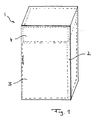
- FIG. 1 shows a one-door refrigerator and freezer 1, in which a door 2 extends over the entire front and covers both a refrigerated goods 3 and a freezer 4.
- the freezer compartment 4 in a conventional manner is substantially smaller than the refrigerated goods 3 and is arranged horizontally above the latter.
- the refrigerator and freezer 1 has a continuous inner container 5, which is made in a suitable method of plastic.
- the inner container 5 is integrally formed in one piece and includes both the freezer compartment 4 defining freezer compartment and the refrigerated goods 3 limitingmégutwanne 7.
- FIG. 2 shows, the freezer compartment 6 is separated only by an approximately hand-thick gap 8 of the refrigerated goods 7, but it is integrally connected integrally with theissergutwanne 7.
- the freezer compartment tray 6 is how FIG. 2 shows, with its opening cross-section of the open front side of the inner container 5 set back to the rear. Said gap 8 between the freezer compartment and theisserwanne 7 extends only about 2/3 to 3/4 of the depth of the inner container 5.
- the freezer compartment 6 is rigidly connected to thedegutwanne 7, ie it can not bent away or bent away to widen the gap 8 for the purpose of evaporator assembly.
- the gap 8 is sufficiently thick to accommodate the evaporator coils.
- a wound box evaporator 9 sits snugly and positively on the freezer compartment tub 6, which is surrounded by the windings 10 of the evaporator 9 all-round.
- the evaporator 9 can cool the freezer in a highly efficient manner.
- the wound evaporator 9 comprises a plurality of coil coils, which may consist of bent aluminum tube.
- the said metal plates are glued by means of double-sided adhesive tape to the walls of the freezer compartment tray 6.
- the windings 10 of the evaporator 9 may also be glued to said metal plates in the manner mentioned. It is understood that On each of the four sides of the freezer compartment 6, which are enclosed by the evaporator 9, such a metal plate may be arranged.
- the evaporator 9 may in particular be a so-called four-staged evaporator with a wound evaporator box system, which is mounted on the freezer compartment tub 6 of a continuous inner container 5 of a one-door refrigerator with freezer compartment.
- a separation of the freezer compartment from the inner container is avoided by this arrangement.
- the continuous container has no parting line and no bending edge between the freezer compartment tray 6 and the refrigerated tray 7, so that no dirt edge can arise and a better appearance is achieved.
- the advantage is achieved that no costly sealing measures in the assembly of the evaporator or the evaporator box system on the inner container 5 must be made.
- the evaporator 9 is not visible from the interior of the device. In summary, it can be said that with low-cost components, a highly efficient evaporator without disadvantages for the user is created.
Landscapes
- Engineering & Computer Science (AREA)
- Chemical & Material Sciences (AREA)
- Combustion & Propulsion (AREA)
- Physics & Mathematics (AREA)
- Mechanical Engineering (AREA)
- Thermal Sciences (AREA)
- General Engineering & Computer Science (AREA)
- Devices That Are Associated With Refrigeration Equipment (AREA)
- Refrigerator Housings (AREA)
Description
- Die vorliegende Erfindung betrifft ein Kühl- und Gefriergerät mit einem durchgehenden Innenbehälter, der eine Gefrierfachwanne und eine Kühlgutwanne bildet, die einstückig ohne Trennfuge und Knickkante biegesteif miteinander verbunden sind, sowie einem auf der Gefrierfachwanne sitzenden Verdampfer.
- Solche Kühl- und Gefriergeräte mit einem durchgehenden Innenbehälter, die üblicherweise als eintürige Geräte ausgebildet werden, besitzen in mehrerer Hinsicht Vorteile. Da keine Abtrennung des Gefrierfachs vorgesehen ist, entsteht zwischen dem Gefrierfach und dem Kühlgutbehälter keine Schmutzkante. Gegenüber Kühl-und Gefriergeräten mit geteiltem Innenbehälter bzw. separater Gefrierfachwanne kann eine wesentlich bessere Optik erreicht werden. Zudem brauchen bei solchen Kühl- und Gefriergeräten mit einem durchgehenden Innenbehälter keine aufwendigen Abdichtungsmaßnahmen bei der Montage des Verdampfers vorgenommen werden. Eim Kühl-und Gefriergerät gemäß dem Oberbegriif von Anspruch 1 ist aus
EP0953812 bekannt. - Soweit bei solchen Geräten der durchgehende Innenbehälter im Übergangsbereich zwischen der Gefrierfachwanne und der Kühlgutwanne biegesteif ausgebildet ist, gestaltet sich jedoch die Montage des Verdampfers aufgrund beengter Platzverhältnisse schwierig. Zwischen der Gefrierfachwanne und der Kühlgutwanne verbleibt oftmals nur ein schmaler Spalt. Es wurde deshalb bislang bei solchen Geräten mit durchgehendem Innenbehälter regelmäßig ein u-förmiger Plattenverdampfer verwendet, der nach Art einer Klammer von der Rückseite her über die Gefrierfachwanne geschoben wurde, so daß der Verdampfer auf der Rückwand sowie zwei gegenüberliegenden Seitenwänden der Gefrierfachwanne an dieser anliegt. Die Kühlleistung einer solchen Anordnung ist jedoch begrenzt.
- Um eine effizientere Gefrierfachkühlung zu erreichen, wurde deshalb bisweilen die einteilige, durchgehende Bauweise des Innenbehälters geopfert, um effizientere Verdampfer verwenden zu können. Insbesondere wurde bereits vorgeschlagen, als Verdampferwanne einen separaten Blechkasten vorzusehen, um den Verdampferrohre gewickelt wurden, die anschließend mit einer Alufolie beklebt wurden. Dieser vormontierte Kasten kann auf dem vorher vom Kühlgutbehälter abgetrennten Gefrierfach montiert werden, wobei allerdings dann zur Montage und Abdichtung des Gefrierfaches ein Spritzrahmen benötigt wird und Montagekanten im Innenbehälter sichtbar bleiben. Insofern ist auch diese Lösung bislang unbefriedigend.
- Der vorliegenden Erfindung liegt daher die Aufgabe zugrunde, ein verbessertes Kühl- und Gefriergerät der eingangs genannten Art mit einem durchgehenden Innenbehälter zu schaffen, das eine effizientere Kühlung des Gefrierfaches erreicht, so daß die Vorteile eines Kühl- und Gefriergerätes mit durchgehendem Innenbehälter mit einer effizienteren Gefrierfachkühlung verbunden werden.
- Erfindungsgemäß wird diese Aufgabe durch ein Kühl- und Gefriergerät gemäß Anspruch 1 gelöst. Vorteilhafte Ausgestaltungen der Erfindung sind Gegenstand der abhängigen Ansprüche.
- Erfindungsgemäß ist also ungeachtet der schwierigen Platz- und Montageverhältnisse bei einem durchgehenden Innenbehälter mit einer biegesteif mit der Kühlgutwanne verbundenen Gefrierfachwanne als Verdampfer ein gewickelter Kastenverdampfer vorgesehen, der die Gefrierfachwanne auf vier Seiten umlaufend umschließt. Im Gegensatz zu den bisher verwendeten u-förmigen Plattenverdampfern erstreckt sich der gewickelte Kastenverdampfer umlaufend um vier Seiten der Gefrierfachwanne herum, einschließlich der Seite der Gefrierfachwanne, die der Kühlgutwanne gegenüberliegt und von dieser nur durch einen schmalen Spalt getrennt ist. Hierdurch kann eine beträchtlich höhere Effizienz erreicht werden. Es ergibt sich auch ohne teureren Kompressor eine wesentlich bessere Gefrierfachleistung, durch die eine hochwertigere Klimaklasse erreicht werden kann. Die Erfindung setzt sich damit erstmalig über das Vorurteil hinweg, daß bei einem Kühl- und Gefriergerät mit durchgehendem Innenbehälter, bei dem die einstückig angeformte Gefrierfachwanne biegesteif mit der Kühlgutwanne verbunden ist, nur ein bestimmter Verdampfertypus, insbesondere ein u-förmiger Plattenverdampfer verwendbar sei. Durch den erfindungsgemäß vorgesehenen gewickelten Verdampferkasten verbindet die vorliegende Erfindung die Vorteile eines Kühl- und Gefriergerätes mit durchgehendem Innenbehälter mit einer hocheffizienten Gefrierfachkühlung.
- Vorteilhafterweise ist der Verdampfer festsitzend auf der Gefrierfachwanne angeordnet. Der Verdampfer kann sozusagen mit einer leichten Preßpassung auf der Gefrierfachwanne sitzen, so daß ein satter Kontakt zwischen der Gefrierfachwanne und den formschlüssig darauf sitzenden Wickelschlangen des Verdampfers und ein dementsprechend günstiger Wärmeübergang erreicht wird.
- In Weiterbildung der Erfindung ist der Verdampfer mit der Gefrierfachwanne verklebt. Insbesondere kann der gewickelte Kastenverdampfer mit der Gefrierfachwanne durch ein doppelseitig klebendes Klebeband oder eine entsprechende Klebefolie verbunden sein. Ein solches doppelseitig klebendes Klebeband bewirkt einerseits eine gute, strapazierfähige Verbindung, andererseits vermeidet es die bei anderen Klebstoffen oftmals einzuhaltende Abbindezeit.
- Der gewickelte Kastenverdampfer kann grundsätzlich mit seinen gewickelten Verdampferrohren unmittelbar auf der Gefrierfachwanne sitzen. Vorteilhafterweise jedoch sind zwischen der Gefrierfachwanne und der Rohrwicklung des Verdampfers Platten, insbesondere Metallplatten, angeordnet, auf denen die Verdampferwicklung aufgebracht ist. Die Platten sind mit ihrer Innenseite vorteilhafterweise in der zuvor beschriebenen Weise mit der Gefrierfachwanne des Innenbehälters verklebt. Die Metallplatten zwischen der Verdampferwicklung und der Gefrierfachwanne stellen einen vollflächigen Wärmeübergang von der Gefrierfachwanne sicher.
- Insbesondere ist das Kühl- und Gefriergerät als eintüriges Gerät ausgebildet, bei dem sich die Gerätetür sowohl über den Kühlgutbehälter als auch das Gefrierfach hinweg erstreckt. Das Gefrierfach kann hierbei mit seinem Öffnungsquerschnitt gegenüber dem Kühlgutbehälter nach hinten, d.h. zur Geräterückseite hin zurückversetzt sein. Der Spalt zwischen der Gefrierfachwanne und der Kühlgutwanne kann sich bei einem solchen Gerätetyp über weniger als 4/5 der Innenbehältertiefe erstrecken.
- Die Erfindung wird nachfolgend anhand eines Ausführungsbeispiels und zugehöriger Zeichnungen näher erläutert. In den Zeichnungen zeigen:
- Figur 1:
- eine schematische perspektivische Gesamtansicht eines Kühl- und Gefriergeräts nach einem Ausführungsbeispiel der Erfindung,
- Figur 2:
- eine perspektivische Seiten-/Rückansicht des Innenbehälters des Kühl-und Gefriergeräts aus
Figur 1 , die den gewickelten Kastenverdampfer zeigt, der auf der Gefrierfachwanne des Innenbehälters sitzt, und - Figur 3:
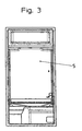
- eine Frontansicht des Innenbehälters des Kühl- und Gefriergeräts aus den vorhergehenden Figuren.
-
Figur 1 zeigt ein eintüriges Kühl- und Gefriergerät 1, bei dem eine Gerätetür 2 sich über die gesamte Frontseite erstreckt und sowohl einen Kühlgutbehälter 3 als auch ein Gefrierfach 4 überdeckt. WieFigur 1 zeigt, ist das Gefrierfach 4 in an sich bekannter Weise wesentlich kleiner als der Kühlgutbehälter 3 und ist über Letzterem liegend angeordnet. - Wie
Figur 2 undFigur 3 zeigt, besitzt das Kühl- und Gefriergerät 1 einen durchgehenden Innenbehälter 5, der in einem geeigneten Verfahren aus Kunststoff hergestellt wird. Der Innenbehälter 5 ist integral einstückig ausgebildet und umfaßt sowohl die das Gefrierfach 4 definierende Gefrierfachwanne als auch die den Kühlgutbehälter 3 begrenzende Kühlgutwanne 7. WieFigur 2 zeigt, ist die Gefrierfachwanne 6 nur durch einen etwa handdicken Spalt 8 von der Kühlgutwanne 7 getrennt, wobei sie jedoch mit der Kühlgutwanne 7 integral einstückig verbunden ist. Die Gefrierfachwanne 6 ist dabei, wieFigur 2 zeigt, mit ihrem Öffnungsquerschnitt von der offenen Frontseite des Innenbehälters 5 nach hinten zurückversetzt. Der genannte Spalt 8 zwischen der Gefrierfachwanne und der Kühlgutwanne 7 erstreckt sich nur etwa über 2/3 bis 3/4 der Tiefe des Innenbehälters 5. Bei dieser Gestaltung des Innenbehälters 5 ist die Gefrierfachwanne 6 mit der Kühlgutwanne 7 biegesteif verbunden, d.h. sie kann nicht weggebogen oder weggeknickt werden, um den Spalt 8 zum Zweck der Verdampfermontage zu verbreitern. Der Spalt 8 ist jedoch ausreichend dick, um die Verdampferwicklungen aufzunehmen. - Wie
Figur 2 zeigt, sitzt ein gewickelter Kastenverdampfer 9 paßgenau und formschlüssig auf der Gefrierfachwanne 6, die von den Wicklungen 10 des Verdampfers 9 vielseitig umlaufend umschlossen ist. In der gezeichneten Ausführung bleibt lediglich die Rückwand der Verdampferwanne von dem gewickelten Verdampfer 9 unbedeckt. Durch die vielseitige Umschließung der Verdampferwanne kann der Verdampfer 9 höchst effizient das Gefrierfach kühlen. - Wie
Figur 2 zeigt, umfaßt der gewickelte Verdampfer 9 eine Vielzahl von Wicklungsschlangen, die aus gebogenem Aluminiumrohr bestehen können. Vorteilhafterweise sitzen zwischen der Gefrierfachwanne 6 und den Wicklungen 10 des Verdampfers 9 in der Zeichnung nicht sichtbare Metallplatten, auf denen die Wicklungen 10 des Verdampfers 9 angeordnet sind. Die genannten Metallplatten werden mittels doppelseitig klebendem Klebeband an den Wandungen der Gefrierfachwanne 6 festgeklebt. Die Wicklungen 10 des Verdampfers 9 können an den genannten Metallplatten ebenfalls in der genannten Weise verklebt sein. Es versteht sich, daß auf jeder der vier Seiten der Gefrierfachwanne 6, die von dem Verdampfer 9 umschlossen sind, eine solche Metallplatte angeordnet sein kann. - Der Verdampfer 9 kann insbesondere ein sogenannter Vierstemeverdampfer mit gewickeltem Verdampferkastensystem sein, der auf der Gefrierfachwanne 6 eines durchgehenden Innenbehälters 5 eines eintürigen Kühlgeräts mit Gefrierfach montiert ist. Vorteilhafterweise wird durch diese Anordnung eine Abtrennung des Gefrierfaches vom Innenbehälter vermieden. Der durchgehende Behälter besitzt keine Trennfuge und auch keine Biegekante zwischen der Gefrierfachwanne 6 und der Kühlgutwanne 7, so daß keine Schmutzkante entstehen kann und eine bessere Optik erreicht wird. Zudem wird der Vorteil erreicht, daß keine aufwendigen Abdichtmaßnahmen bei der Montage des Verdampfers oder des Verdampferkastensystems auf dem Innenbehälter 5 vorgenommen werden müssen. Zudem ist der Verdampfer 9 vom Geräteinnenraum nicht sichtbar. Zusammenfassend läßt sich sagen, daß mit kostengünstigen Bauteilen ein hocheffizienter Verdampfer ohne Nachteile für den Anwender geschaffen wird.
Claims (7)
- Kühl- und Gefriergerät mit einem durchgehenden Innenbehälter (5), der eine Gefrierfachwanne (6) und eine Kühlgutwanne (7) bildet, die einstückig ohne Trennfuge und Knickkante biegesteif miteinander verbunden sind, sowie einem auf der Gefrierfachwanne (6) sitzenden Verdampfer (9), dadurch gekennzeichnet, daß als Verdampfer (9) ein gewickelter Kastenverdampfer vorgesehen ist, der die Gefrierfachwanne (6) auf vier Seiten umlaufend umschließt.
- Kühl- und Gefriergerät nach dem vorhergehenden Anspruch, wobei der Verdampfer (9) festsitzend formschlüssig auf der Gefrierfachwanne (6) angeordnet ist.
- Kühl- und Gefriergerät nach einem der vorhergehenden Ansprüche, wobei der Verdampfer (9) mit der Gefrierfachwanne (6) verklebt ist, insbesondere durch ein doppelseitiges Klebeband oder eine doppelseitige Klebefolie mit der Gefrierfachwanne (6) verbunden ist.
- Kühl- und Gefriergerät nach einem der vorhergehenden Ansprüche, wobei zwischen der Gefrierfachwanne (6) und dem Verdampfer (9) Platten, insbesondere Metallplatten, angeordnet sind, auf denen die Verdampferwicklungen (10) aufgebracht sind.
- Kühl- und Gefriergerät nach einem der vorhergehenden Ansprüche, wobei zwischen der Gefrierfachwanne (6) und der Kühlgutwanne (7) ein Spalt (8) vorgesehen ist, dessen Dicke nur geringfügig größer als die Dicke der Verdampferwicklungen (10) ist.
- Kühl- und Gefriergerät nach einem der vorhergehenden Ansprüche, wobei die Gefrierfachwanne (6) mit ihrem Öffnungsquerschnitt gegenüber der Kühlgutwanne (7) zur Geräterückseite hin zurückversetzt ist.
- Kühl- und Gefriergerät nach einem der vorhergehenden Ansprüche, wobei es als eintüriges Gerät ausgebildet ist.
Applications Claiming Priority (3)
| Application Number | Priority Date | Filing Date | Title |
|---|---|---|---|
| DE202004020069 | 2004-12-28 | ||
| DE202005000909U DE202005000909U1 (de) | 2004-12-28 | 2005-01-20 | Kühl- und Gefriergerät |
| PCT/EP2005/014075 WO2006069783A1 (de) | 2004-12-28 | 2005-12-27 | Kühl- und gefriergerät |
Publications (2)
| Publication Number | Publication Date |
|---|---|
| EP1831625A1 EP1831625A1 (de) | 2007-09-12 |
| EP1831625B1 true EP1831625B1 (de) | 2008-08-27 |
Family
ID=36072061
Family Applications (1)
| Application Number | Title | Priority Date | Filing Date |
|---|---|---|---|
| EP05850364A Expired - Lifetime EP1831625B1 (de) | 2004-12-28 | 2005-12-27 | Kühl- und gefriergerät |
Country Status (9)
| Country | Link |
|---|---|
| US (1) | US20080264096A1 (de) |
| EP (1) | EP1831625B1 (de) |
| JP (1) | JP2008525756A (de) |
| KR (1) | KR20070112450A (de) |
| AT (1) | ATE406552T1 (de) |
| DE (2) | DE202005000909U1 (de) |
| ES (1) | ES2309830T3 (de) |
| RU (1) | RU2371646C2 (de) |
| WO (1) | WO2006069783A1 (de) |
Families Citing this family (12)
| Publication number | Priority date | Publication date | Assignee | Title |
|---|---|---|---|---|
| US7240080B2 (en) * | 2003-07-30 | 2007-07-03 | International Business Machines Corporation | Method and apparatus for determining using least recently used protocol if one or more computer files should be written to one or more information storage media and synchronously providing one or more computer files between first and storage devices |
| DE202006013232U1 (de) * | 2006-08-29 | 2006-10-19 | BSH Bosch und Siemens Hausgeräte GmbH | Kältegerät mit Halterungen für einen Kühlgutträger |
| US8011191B2 (en) | 2009-09-30 | 2011-09-06 | Thermo Fisher Scientific (Asheville) Llc | Refrigeration system having a variable speed compressor |
| DE102010028527A1 (de) | 2010-05-04 | 2011-11-10 | BSH Bosch und Siemens Hausgeräte GmbH | Kältegerät und Verdampfer dafür |
| DE102010028526A1 (de) | 2010-05-04 | 2011-11-10 | BSH Bosch und Siemens Hausgeräte GmbH | Kältegerät und Verdampfer dafür |
| WO2014086860A1 (en) | 2012-12-05 | 2014-06-12 | Arcelik Anonim Sirketi | A cooling device comprising an evaporator |
| DE102012222846A1 (de) | 2012-12-12 | 2014-06-12 | BSH Bosch und Siemens Hausgeräte GmbH | Haushaltskältegerät mit einem Innenbehälter und einem Verdampfer, der eine Gefrierfachwanne umgibt, sowie Verfahren zum Anbringen eines Verdampfers an einem Innenbehälter eines Haushaltskältegeräts |
| EP2829828B1 (de) | 2013-07-25 | 2016-06-29 | Electrolux Appliances Aktiebolag | Verfahren zum Herstellen einer Kühlvorrichtung |
| DE102013215491A1 (de) | 2013-08-06 | 2015-02-12 | BSH Bosch und Siemens Hausgeräte GmbH | Kombinationskältegerät |
| DE102014004690A1 (de) * | 2014-01-29 | 2015-07-30 | Liebherr-Hausgeräte Ochsenhausen GmbH | Kühl- und/oder Gefriergerät |
| EP3006868A1 (de) | 2014-10-10 | 2016-04-13 | Indesit Company S.p.A. | Abtauen eines eisfachs eines kühlgeräts und zugehöriges kühlgerät |
| CN104567197B (zh) * | 2015-01-07 | 2017-08-15 | 合肥美的电冰箱有限公司 | 冰箱 |
Family Cites Families (13)
| Publication number | Priority date | Publication date | Assignee | Title |
|---|---|---|---|---|
| US2576208A (en) * | 1949-01-21 | 1951-11-27 | Avco Mfg Corp | Refrigerator cabinet construction having heat exchange inner walls |
| DE929067C (de) * | 1952-04-17 | 1955-06-20 | Gen Motors Corp | Kuehlschrank mit Tiefkuehl- und Aufbewahrungsabteil |
| US2739456A (en) * | 1953-07-21 | 1956-03-27 | Gen Motors Corp | Two temperature refrigerator |
| DE2039246C3 (de) * | 1970-08-07 | 1980-02-07 | Bosch-Siemens Hausgeraete Gmbh, 7000 Stuttgart | Kühlschrank, insbesondere Zweitemperaturen-Kuhlschrank |
| IT8334019V0 (it) * | 1983-04-22 | 1983-04-22 | Zanussi A Spa Industrie | Evaporatore frigorifero. |
| IT213782Z2 (it) * | 1988-05-04 | 1990-03-01 | Eurodomestici Ind Riunite | Evaporatore per frigoriferi statici. |
| IT1289400B1 (it) * | 1996-11-26 | 1998-10-02 | Electrolux Zanussi Elettrodome | Metodo per produrre uno scambiatore di calore per un apparecchio refrigerante e scambiatore di calore cosi' prodotto |
| DE29722661U1 (de) * | 1997-12-22 | 1998-05-07 | Bosch-Siemens Hausgeräte GmbH, 81669 München | Verdampferanordnung |
| IT246294Y1 (it) * | 1998-01-09 | 2002-04-08 | Whirlpool Co | Frigorifero domestico |
| DE19818288B4 (de) * | 1998-04-23 | 2009-04-30 | BSH Bosch und Siemens Hausgeräte GmbH | Kühlgerät |
| DE10143241A1 (de) * | 2001-09-04 | 2003-03-20 | Bsh Bosch Siemens Hausgeraete | Kältegerät mit Coldwall-Verdampfer |
| US6536227B1 (en) * | 2002-01-29 | 2003-03-25 | Daewoo Electronics Corporation | Direct cooling type refrigerator |
| DE10221898B4 (de) * | 2002-05-16 | 2005-01-27 | BSH Bosch und Siemens Hausgeräte GmbH | Kältegerät mit beheizbarem Innenraum |
-
2005
- 2005-01-20 DE DE202005000909U patent/DE202005000909U1/de not_active Expired - Lifetime
- 2005-12-27 AT AT05850364T patent/ATE406552T1/de not_active IP Right Cessation
- 2005-12-27 KR KR1020077017286A patent/KR20070112450A/ko not_active Withdrawn
- 2005-12-27 ES ES05850364T patent/ES2309830T3/es not_active Expired - Lifetime
- 2005-12-27 US US11/794,382 patent/US20080264096A1/en not_active Abandoned
- 2005-12-27 DE DE502005005223T patent/DE502005005223D1/de not_active Expired - Lifetime
- 2005-12-27 WO PCT/EP2005/014075 patent/WO2006069783A1/de not_active Ceased
- 2005-12-27 RU RU2007129019/12A patent/RU2371646C2/ru active
- 2005-12-27 EP EP05850364A patent/EP1831625B1/de not_active Expired - Lifetime
- 2005-12-27 JP JP2007548752A patent/JP2008525756A/ja active Pending
Also Published As
| Publication number | Publication date |
|---|---|
| DE502005005223D1 (de) | 2008-10-09 |
| ES2309830T3 (es) | 2008-12-16 |
| EP1831625A1 (de) | 2007-09-12 |
| RU2007129019A (ru) | 2009-02-10 |
| US20080264096A1 (en) | 2008-10-30 |
| DE202005000909U1 (de) | 2006-05-04 |
| ATE406552T1 (de) | 2008-09-15 |
| JP2008525756A (ja) | 2008-07-17 |
| KR20070112450A (ko) | 2007-11-26 |
| RU2371646C2 (ru) | 2009-10-27 |
| WO2006069783A1 (de) | 2006-07-06 |
Similar Documents
| Publication | Publication Date | Title |
|---|---|---|
| EP1831625A1 (de) | Kühl- und gefriergerät | |
| DE29912917U1 (de) | Wärmeisolierende Wandung | |
| EP1430261B1 (de) | Gehäuse für ein kältegerät | |
| WO2004104502A1 (de) | Tür für ein kältegerät | |
| WO2014095528A1 (de) | Trägerrahmen für einen isolationskörper mit einer dichtung an der innenwand sowie haushaltskältegerät | |
| WO1999020963A1 (de) | Wärmeisolierendes gehäuse | |
| DE102010040250A1 (de) | Kältegerät, insbesondere Haushaltskältegerät | |
| EP2641040B1 (de) | Kältegerätetür | |
| EP3447416B1 (de) | Kühl- und/oder gefriergerät und verfahren zur herstellung davon | |
| DE102011082790A1 (de) | Kältegerät, insbesondere Haushaltskältegerät | |
| DE3319865C2 (de) | Kühlgerät mit einer Nische für einen Motorkompressor | |
| DE4420149A1 (de) | Kühlanlage mit Kühlraum, sowie Isolierpaneel mit integrierten Luftkühlerbauelementen für einen Kühlraum | |
| DE102011082789A1 (de) | Kältegerät, insbesondere Haushaltskältegerät | |
| DE19712140A1 (de) | Kühl- und/oder Gefriergerät mit einem wärmeisolierten Gehäuse und Verfahren zur Herstellung eines Kühl- und/oder Gefriergeräts mit einem wärmeisolierten Gehäuse | |
| EP1712857A2 (de) | Kühl- und/oder Gefriergerät | |
| WO2000049351A1 (de) | Kältegerätetür | |
| DE102012208600A1 (de) | Kältegerät, insbesondere Haushaltskältegerät | |
| DE19528774A1 (de) | Kältegerät, wie Haushalts-Kühl- oder Gefriergerät | |
| DE19808227C9 (de) | Verfahren zur Herstellung eines Gehäuses für ein Kühl- und/oder Gefriergerät | |
| DE102010032060B4 (de) | Kühl- und/oder Gefriergerät | |
| EP3447419A1 (de) | Kühl- und/oder gefriergerät | |
| EP2641041B1 (de) | Kältegerätetür | |
| DE102024115346A1 (de) | Kühl- und/oder Gefriergerät | |
| DE102022200028A1 (de) | Haushaltskältegerät mit einem konfigurierbaren Gehäuse, sowie Verfahren zur Montage eines Haushaltskältegeräts | |
| DE7708579U1 (de) | Kuehlmoebel, insbesondere kuehl- oder gefrierschrank |
Legal Events
| Date | Code | Title | Description |
|---|---|---|---|
| PUAI | Public reference made under article 153(3) epc to a published international application that has entered the european phase |
Free format text: ORIGINAL CODE: 0009012 |
|
| 17P | Request for examination filed |
Effective date: 20070619 |
|
| AK | Designated contracting states |
Kind code of ref document: A1 Designated state(s): AT BE BG CH CY CZ DE DK EE ES FI FR GB GR HU IE IS IT LI LT LU LV MC NL PL PT RO SE SI SK TR |
|
| RIN1 | Information on inventor provided before grant (corrected) |
Inventor name: SCHMID, EUGEN Inventor name: LAUBE, VIKTOR Inventor name: WIEST, MATTHIAS Inventor name: JENDRUSCH, HOLGER Inventor name: SIEGEL, DIDIER |
|
| DAX | Request for extension of the european patent (deleted) | ||
| GRAP | Despatch of communication of intention to grant a patent |
Free format text: ORIGINAL CODE: EPIDOSNIGR1 |
|
| GRAS | Grant fee paid |
Free format text: ORIGINAL CODE: EPIDOSNIGR3 |
|
| GRAA | (expected) grant |
Free format text: ORIGINAL CODE: 0009210 |
|
| AK | Designated contracting states |
Kind code of ref document: B1 Designated state(s): AT BE BG CH CY CZ DE DK EE ES FI FR GB GR HU IE IS IT LI LT LU LV MC NL PL PT RO SE SI SK TR |
|
| REG | Reference to a national code |
Ref country code: GB Ref legal event code: FG4D Free format text: NOT ENGLISH |
|
| REG | Reference to a national code |
Ref country code: CH Ref legal event code: EP |
|
| REG | Reference to a national code |
Ref country code: IE Ref legal event code: FG4D Free format text: LANGUAGE OF EP DOCUMENT: GERMAN |
|
| REF | Corresponds to: |
Ref document number: 502005005223 Country of ref document: DE Date of ref document: 20081009 Kind code of ref document: P |
|
| REG | Reference to a national code |
Ref country code: ES Ref legal event code: FG2A Ref document number: 2309830 Country of ref document: ES Kind code of ref document: T3 |
|
| PG25 | Lapsed in a contracting state [announced via postgrant information from national office to epo] |
Ref country code: LT Free format text: LAPSE BECAUSE OF FAILURE TO SUBMIT A TRANSLATION OF THE DESCRIPTION OR TO PAY THE FEE WITHIN THE PRESCRIBED TIME-LIMIT Effective date: 20080827 Ref country code: IS Free format text: LAPSE BECAUSE OF FAILURE TO SUBMIT A TRANSLATION OF THE DESCRIPTION OR TO PAY THE FEE WITHIN THE PRESCRIBED TIME-LIMIT Effective date: 20081227 Ref country code: NL Free format text: LAPSE BECAUSE OF FAILURE TO SUBMIT A TRANSLATION OF THE DESCRIPTION OR TO PAY THE FEE WITHIN THE PRESCRIBED TIME-LIMIT Effective date: 20080827 |
|
| PG25 | Lapsed in a contracting state [announced via postgrant information from national office to epo] |
Ref country code: SI Free format text: LAPSE BECAUSE OF FAILURE TO SUBMIT A TRANSLATION OF THE DESCRIPTION OR TO PAY THE FEE WITHIN THE PRESCRIBED TIME-LIMIT Effective date: 20080827 Ref country code: LV Free format text: LAPSE BECAUSE OF FAILURE TO SUBMIT A TRANSLATION OF THE DESCRIPTION OR TO PAY THE FEE WITHIN THE PRESCRIBED TIME-LIMIT Effective date: 20080827 Ref country code: FI Free format text: LAPSE BECAUSE OF FAILURE TO SUBMIT A TRANSLATION OF THE DESCRIPTION OR TO PAY THE FEE WITHIN THE PRESCRIBED TIME-LIMIT Effective date: 20080827 |
|
| REG | Reference to a national code |
Ref country code: IE Ref legal event code: FD4D |
|
| PG25 | Lapsed in a contracting state [announced via postgrant information from national office to epo] |
Ref country code: BG Free format text: LAPSE BECAUSE OF FAILURE TO SUBMIT A TRANSLATION OF THE DESCRIPTION OR TO PAY THE FEE WITHIN THE PRESCRIBED TIME-LIMIT Effective date: 20081127 Ref country code: IE Free format text: LAPSE BECAUSE OF FAILURE TO SUBMIT A TRANSLATION OF THE DESCRIPTION OR TO PAY THE FEE WITHIN THE PRESCRIBED TIME-LIMIT Effective date: 20080827 Ref country code: DK Free format text: LAPSE BECAUSE OF FAILURE TO SUBMIT A TRANSLATION OF THE DESCRIPTION OR TO PAY THE FEE WITHIN THE PRESCRIBED TIME-LIMIT Effective date: 20080827 |
|
| PG25 | Lapsed in a contracting state [announced via postgrant information from national office to epo] |
Ref country code: RO Free format text: LAPSE BECAUSE OF FAILURE TO SUBMIT A TRANSLATION OF THE DESCRIPTION OR TO PAY THE FEE WITHIN THE PRESCRIBED TIME-LIMIT Effective date: 20080827 Ref country code: SK Free format text: LAPSE BECAUSE OF FAILURE TO SUBMIT A TRANSLATION OF THE DESCRIPTION OR TO PAY THE FEE WITHIN THE PRESCRIBED TIME-LIMIT Effective date: 20080827 Ref country code: PT Free format text: LAPSE BECAUSE OF FAILURE TO SUBMIT A TRANSLATION OF THE DESCRIPTION OR TO PAY THE FEE WITHIN THE PRESCRIBED TIME-LIMIT Effective date: 20090127 Ref country code: CZ Free format text: LAPSE BECAUSE OF FAILURE TO SUBMIT A TRANSLATION OF THE DESCRIPTION OR TO PAY THE FEE WITHIN THE PRESCRIBED TIME-LIMIT Effective date: 20080827 |
|
| BERE | Be: lapsed |
Owner name: LIEBHERR-HAUSGERATE OCHSENHAUSEN G.M.B.H. Effective date: 20081231 |
|
| PLBE | No opposition filed within time limit |
Free format text: ORIGINAL CODE: 0009261 |
|
| STAA | Information on the status of an ep patent application or granted ep patent |
Free format text: STATUS: NO OPPOSITION FILED WITHIN TIME LIMIT |
|
| PG25 | Lapsed in a contracting state [announced via postgrant information from national office to epo] |
Ref country code: MC Free format text: LAPSE BECAUSE OF NON-PAYMENT OF DUE FEES Effective date: 20081231 Ref country code: EE Free format text: LAPSE BECAUSE OF FAILURE TO SUBMIT A TRANSLATION OF THE DESCRIPTION OR TO PAY THE FEE WITHIN THE PRESCRIBED TIME-LIMIT Effective date: 20080827 |
|
| 26N | No opposition filed |
Effective date: 20090528 |
|
| PG25 | Lapsed in a contracting state [announced via postgrant information from national office to epo] |
Ref country code: BE Free format text: LAPSE BECAUSE OF NON-PAYMENT OF DUE FEES Effective date: 20081231 |
|
| PG25 | Lapsed in a contracting state [announced via postgrant information from national office to epo] |
Ref country code: SE Free format text: LAPSE BECAUSE OF FAILURE TO SUBMIT A TRANSLATION OF THE DESCRIPTION OR TO PAY THE FEE WITHIN THE PRESCRIBED TIME-LIMIT Effective date: 20081127 |
|
| PG25 | Lapsed in a contracting state [announced via postgrant information from national office to epo] |
Ref country code: PL Free format text: LAPSE BECAUSE OF FAILURE TO SUBMIT A TRANSLATION OF THE DESCRIPTION OR TO PAY THE FEE WITHIN THE PRESCRIBED TIME-LIMIT Effective date: 20080827 |
|
| PG25 | Lapsed in a contracting state [announced via postgrant information from national office to epo] |
Ref country code: AT Free format text: LAPSE BECAUSE OF NON-PAYMENT OF DUE FEES Effective date: 20081227 |
|
| PG25 | Lapsed in a contracting state [announced via postgrant information from national office to epo] |
Ref country code: CY Free format text: LAPSE BECAUSE OF FAILURE TO SUBMIT A TRANSLATION OF THE DESCRIPTION OR TO PAY THE FEE WITHIN THE PRESCRIBED TIME-LIMIT Effective date: 20080827 Ref country code: HU Free format text: LAPSE BECAUSE OF FAILURE TO SUBMIT A TRANSLATION OF THE DESCRIPTION OR TO PAY THE FEE WITHIN THE PRESCRIBED TIME-LIMIT Effective date: 20090228 Ref country code: LU Free format text: LAPSE BECAUSE OF NON-PAYMENT OF DUE FEES Effective date: 20081227 |
|
| REG | Reference to a national code |
Ref country code: CH Ref legal event code: PL |
|
| GBPC | Gb: european patent ceased through non-payment of renewal fee |
Effective date: 20091227 |
|
| PG25 | Lapsed in a contracting state [announced via postgrant information from national office to epo] |
Ref country code: CH Free format text: LAPSE BECAUSE OF NON-PAYMENT OF DUE FEES Effective date: 20091231 Ref country code: GR Free format text: LAPSE BECAUSE OF FAILURE TO SUBMIT A TRANSLATION OF THE DESCRIPTION OR TO PAY THE FEE WITHIN THE PRESCRIBED TIME-LIMIT Effective date: 20081128 Ref country code: LI Free format text: LAPSE BECAUSE OF NON-PAYMENT OF DUE FEES Effective date: 20091231 |
|
| PG25 | Lapsed in a contracting state [announced via postgrant information from national office to epo] |
Ref country code: GB Free format text: LAPSE BECAUSE OF NON-PAYMENT OF DUE FEES Effective date: 20091227 |
|
| PGFP | Annual fee paid to national office [announced via postgrant information from national office to epo] |
Ref country code: TR Payment date: 20081229 Year of fee payment: 4 |
|
| PG25 | Lapsed in a contracting state [announced via postgrant information from national office to epo] |
Ref country code: TR Free format text: LAPSE BECAUSE OF NON-PAYMENT OF DUE FEES Effective date: 20091227 |
|
| REG | Reference to a national code |
Ref country code: FR Ref legal event code: PLFP Year of fee payment: 11 |
|
| REG | Reference to a national code |
Ref country code: FR Ref legal event code: PLFP Year of fee payment: 12 |
|
| REG | Reference to a national code |
Ref country code: FR Ref legal event code: PLFP Year of fee payment: 13 |
|
| PGFP | Annual fee paid to national office [announced via postgrant information from national office to epo] |
Ref country code: FR Payment date: 20181221 Year of fee payment: 14 |
|
| PG25 | Lapsed in a contracting state [announced via postgrant information from national office to epo] |
Ref country code: FR Free format text: LAPSE BECAUSE OF NON-PAYMENT OF DUE FEES Effective date: 20191231 |
|
| PGFP | Annual fee paid to national office [announced via postgrant information from national office to epo] |
Ref country code: IT Payment date: 20201231 Year of fee payment: 16 |
|
| PGFP | Annual fee paid to national office [announced via postgrant information from national office to epo] |
Ref country code: ES Payment date: 20210108 Year of fee payment: 16 |
|
| PG25 | Lapsed in a contracting state [announced via postgrant information from national office to epo] |
Ref country code: IT Free format text: LAPSE BECAUSE OF NON-PAYMENT OF DUE FEES Effective date: 20211227 |
|
| REG | Reference to a national code |
Ref country code: ES Ref legal event code: FD2A Effective date: 20230223 |
|
| PG25 | Lapsed in a contracting state [announced via postgrant information from national office to epo] |
Ref country code: ES Free format text: LAPSE BECAUSE OF NON-PAYMENT OF DUE FEES Effective date: 20211228 |
|
| PGFP | Annual fee paid to national office [announced via postgrant information from national office to epo] |
Ref country code: DE Payment date: 20221229 Year of fee payment: 18 |
|
| REG | Reference to a national code |
Ref country code: DE Ref legal event code: R119 Ref document number: 502005005223 Country of ref document: DE |
|
| PG25 | Lapsed in a contracting state [announced via postgrant information from national office to epo] |
Ref country code: DE Free format text: LAPSE BECAUSE OF NON-PAYMENT OF DUE FEES Effective date: 20240702 |
|
| PG25 | Lapsed in a contracting state [announced via postgrant information from national office to epo] |
Ref country code: DE Free format text: LAPSE BECAUSE OF NON-PAYMENT OF DUE FEES Effective date: 20240702 |