EP1830554A2 - Bilderzeugungsvorrichtung - Google Patents
Bilderzeugungsvorrichtung Download PDFInfo
- Publication number
- EP1830554A2 EP1830554A2 EP07103047A EP07103047A EP1830554A2 EP 1830554 A2 EP1830554 A2 EP 1830554A2 EP 07103047 A EP07103047 A EP 07103047A EP 07103047 A EP07103047 A EP 07103047A EP 1830554 A2 EP1830554 A2 EP 1830554A2
- Authority
- EP
- European Patent Office
- Prior art keywords
- random number
- gray scale
- line
- sub
- calculation
- Prior art date
- Legal status (The legal status is an assumption and is not a legal conclusion. Google has not performed a legal analysis and makes no representation as to the accuracy of the status listed.)
- Withdrawn
Links
Images







Classifications
-
- H—ELECTRICITY
- H04—ELECTRIC COMMUNICATION TECHNIQUE
- H04N—PICTORIAL COMMUNICATION, e.g. TELEVISION
- H04N1/00—Scanning, transmission or reproduction of documents or the like, e.g. facsimile transmission; Details thereof
- H04N1/40—Picture signal circuits
- H04N1/40025—Circuits exciting or modulating particular heads for reproducing continuous tone value scales
Definitions
- the invention relates to an image forming apparatus, specially relates to an image forming apparatus which expresses gray scale data through repeating a plurality of lamp lighting patterns corresponding to different positions.
- Such image forming apparatus comprises a gray scale value inputting register to input gray scale data of n-bits and a dot forming section which forms sub-dots on plural of sub-lines to corresponding to the inputted gray scale value of n-bits received from the gray scale value inputting register.
- the dot forming section sets weight factor to corresponding lamp lighting time. That is, with respect to the same sub-line, a fixed weight factor is set.
- Fig. 12 is an explanation diagram of inputted gray scale value.
- the Fig. 12 shows gray scale value of 4-bits received by the above-stated conventional image forming apparatus via the gray scale value inputting register.
- the Y-axis direction indicates an assistant scanning direction, on the most left queue, respective line numbers are shown; and the X-axis direction indicates an main scanning direction, on the highest row, respective pixel numbers on each line are shown; further, on each column, a gray scale value of pixel specified by the corresponding line number and the corresponding pixel number is stated.
- the Fig. 12 shows a case that gray scale values are orderly inputted to the gray scale value inputting register.
- the gray scale values (1, 1, 1, 1, 1, 1, 1, 1, 1, 1) is inputted;
- the gray scale values (1, 1, 1, 1, 1, 1, 1, 1, 1) is inputted;
- the gray scale values (1, 1, 1, 1, 1, 1, 1, 1, 1) is inputted;
- the gray scale values (1, 1, 1, 1, 1, 1, 1, 1, 1) is inputted;
- the gray scale values (1, 1, 1, 1, 1, 1, 1, 1, 1, 1, 1) is inputted;
- the gray scale values (13, 13, 13, 13, 13, 13, 13, 13, 13, 13) is inputted;
- at timing of line 6 the gray scale values (13, 13, 13, 13, 13, 13, 13, 13, 13, 13) is inputted;
- at timing of line 7, the gray scale values (1, 1, 1, 1, 1, 1, 1, 1, 1, 1) is inputted;
- at timing of line 8 the gray scale values (1, 1, 1, 1, 1, 1, 1, 1, 1, 1, 1) is inputted; and
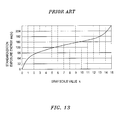
- Fig. 13 is an explanation diagram of a relation between a gray scale value and a standardization exposure energy of each pixel.
- the Fig. 13 shows a relation between a gray scale value k (X-axis) and a standardization exposure energy es(k) (Y-axis) with respect to an actual LED printer.
- Fig. 14 is an explanation diagram of a conventional pixel forming method.
- the Y-axis direction indicates an assistant scanning direction, on the most left queue, respective line numbers are shown; and the X-axis direction indicates an main scanning direction, on the highest row, respective pixel numbers on each line are shown.
- 8 sub-lines (0, 1, 2, 3, 4, 5, 6, 7) will be formed in the assistant scanning direction per 1/4800 inch.
- the standardization exposure energy es(k) of each pixel is divided into bit data of 8-bits, and they, as sub-dots, are respectively indicated on the 8 sub-lines (0, 1, 2, 3, 4, 5, 6, 7).
- a weight factor of 1 is set; in the sub-line 1, a weight factor of 2 is set; in the sub-line 2, a weight factor of 4 is set; in the sub-line 3, a weight factor of 8 is set; in the sub-line 4, a weight factor of 16 is set; in the sub-line 5, a weight factor of 32 is set; in the sub-line 6, a weight factor of 64 is set; and in the sub-line 7, a weight factor of 128 is set.
- the strobe time is identically set, and it becomes unnecessary to set strobe time per pixel on the corresponding line. As a result, it also becomes unnecessary to set memory for memorizing strobe time per pixel, then it is possible to lowly inhibit cost and to increase the gray scale of each pixel.
- Patent document 1 Japan patent publication 2005-22410 .
- an image forming apparatus which expresses lamp lighting energy corresponding to gray scale data on the basis of on/off of lighting lamp of plural dots corresponding to different lamp lighting times of respective different scanning positions, comprising a random number modulation controlling section which, with respect to a lamp lighting energy, executes a random number addition calculation of predetermined level whenever the gray scale data is inputted.
- the predetermined level may correspond to the on/off of one dot whose lamp lighting time is shortest in the different lamp lighting times of respective different scanning positions.
- the random number modulation controlling section may have a random generator to respectively generate 1 or 0 in a predetermined cycle and a probability of 1/2.
- the image forming apparatus may further comprise a modulation control selecting section which, with respect to a composed center position of the lamp lighting energy in plural the dots and a predetermined ideal center position, compares their difference quantities before and after the random number addition calculation, if the difference quantity after the random number addition calculation is bigger than the difference quantity before the random number addition calculation, stops the random number modulation controlling section to operate.
- a modulation control selecting section which, with respect to a composed center position of the lamp lighting energy in plural the dots and a predetermined ideal center position, compares their difference quantities before and after the random number addition calculation, if the difference quantity after the random number addition calculation is bigger than the difference quantity before the random number addition calculation, stops the random number modulation controlling section to operate.
- the modulation control selecting section may previously have random number modulation control information as a judgment standard to judge whether the difference quantity after the random number addition calculation is bigger than the difference quantity before the random number addition calculation, per gray scale value of the inputted gray scale data.
- an image forming apparatus which executes a light emission control where light emitting elements emit light according to a plurality of gray scale data corresponding to an image, comprising:
- the predetermined range may be a value which corresponds to a shortest lighting-lamp control time of the light emitting elements.
- the random number calculation controlling section may add a value of the predetermined range in a probability of 1/2.
- the image forming apparatus may further comprise a calculation control selecting section which, when the random number calculation controlling section executes a random number addition calculation with respect to the gray scale data in the predetermined range, if detected that the gray scale data before the random number addition calculation is not in a concentration range previously stored, makes the random number calculation controlling section output the gray scale data without executing the random number addition calculation.
- the predetermined range may be a range to indicate one of the plurality of gray scale data; the calculation control selecting section individually performs detection with respect to the plurality of gray scale data.
- an image forming apparatus which executes a light emission control where LED elements that are arranged emit light according to a plurality of gray scale data corresponding to an image, and forms a gray scale image, comprising:
- the predetermined range may be a value which corresponds to a shortest lighting-lamp control time of the LED elements.
- the random number calculation controlling section may add a value of the predetermined range in a probability of 1/2.
- the image forming apparatus may further comprise a calculation control selecting section which, when the random number calculation controlling section executes a random number addition calculation with respect to the gray scale data in the predetermined range, if detected that the gray scale data before the random number addition calculation is not in a concentration range previously stored, makes the random number calculation controlling section output the gray scale data without executing the random number addition calculation.
- the predetermined range may be a range to indicate one of the plurality of gray scale data; the calculation control selecting section individually performs detection with respect to the plurality of gray scale data.
- the present invention through providing a random number modulation controlling section and adding a random number to a lamp lighting energy, in the assistant scanning direction, with respect to such image that rapidly changes from a state close to white level toward a state close to black level, or with respect to such image that rapidly changes from a state close to black level toward a state close to white level, it is possible to decrease that a thin white stripe or a thin black stripe happens on the border portion.
- Fig. 1 is a summary diagram showing a LED printer.
- the Fig. 1 shows a summary side view of main mechanism part of an electrophotography printer.
- 11 indicates a photosensitive body drum, which is an image carrying body furnished rotating-freely.
- 61 indicates a charging roller, which is furnished rotating-freely so as to contact with the photosensitive body drum 11, and is a roller to making the surface of the photosensitive body drum 11 be uniformly charged with negative electric charge.
- 12 indicates a LED head (which will be explained below in detail again), which is an exposing device for forming an electrostatic latent image on the surface of the photosensitive body drum 11 on the basis of DATA signal received from a print controlling section.
- a print controlling section (which will be explained below in detail again), which is a part to receive image data from a host apparatus (not shown), and generate print data, then send out the print data as DATA signal to the LED head 12.
- 62 indicates a developing device, which has a developing roller 63, a sponge roller 64, a developing blade 65 and a toner cartridge 66, and is a part to form a toner image as a visible image on the surface of the photosensitive body drum 11.
- 67 indicates a transferring roller, which is rotating-freely furnished so as to contact with the photosensitive body drum 11, and transfers the toner image formed on the photosensitive body drum 11 onto a predetermined record medium.
- 68 is a cleaning blade, which is rotating-freely furnished so as to contact with the photosensitive body drum 11, and is a blade to remove toner remaining on the surface of the photosensitive body drum 11.
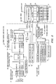
- Fig. 2 is a block diagram showing a print controlling section and a structure of LED head of embodiment 1.
- the print controlling section 13 includes a gray scale value input register 31, a gray scale value/energy transforming section 32, an adding circuit 33, a random generator 34, an energy/lamp lighting pattern transforming section 35, a binary sub-line buffer group 36, a data multiplexer 37, a dot timing producing circuit 38, a line timing producing circuit 39, a strobe time register group 40, a strobe time multiplexer 41, a sub-line counter 42, and a strobe signal producing circuit 43.
- the gray scale value input register 31 has n registers from r[0] to r[n-1], and it is a part to receive a n-bits gray scale value corresponding to each pixel from a host apparatus (not shown).
- the gray scale value/energy transforming section 32 receives the n-bits gray scale value (adr[0] ⁇ adr[n-1]) from the gray scale value input register 31, and transforms the n-bits gray scale value (adr[0] ⁇ adr[n-1]) into the standardization exposure energy es(k), then sends out the standardization exposure energy es(k) to the adding circuit 33.
- the transformation from the n-bits gray scale value (adr[0] ⁇ adr[n-1]) to the standardization exposure energy es(k) is executed through that the gray scale value/energy transforming section 32 uses the relation shown by the Fig. 13 as an example.
- the relation between the gray scale value k and the standardization exposure energy es(k) is shown by a curve in the Fig. 13 and is obtained by previously using a corresponding LED printer, receiving a gray scale value k of 4-bits (an example), measuring an exposure energy e(k) and finding a standardization exposure energy es(k).
- the gray scale value/energy transforming section 32 receives the gray scale value k from the gray scale value input register 31, then transforms the gray scale value k into the standardization exposure energy es(k) expressed by value of 0 ⁇ 256, and outputs the standardization exposure energy es(k) to the adding circuit 33.
- the adding circuit 33 receives the standardization exposure energy es(k) from the gray scale value/energy transforming section 32, further receives a random number signal ⁇ from the random generator 34, then adds the standardization exposure energy es(k) to the random number signal ⁇ , and sends out the addition result serving as a random number addition standardization exposure energy es*(k) to the energy/lamp lighting pattern transforming section 35.
- ⁇ is a random number value received from the random generator 34, and it is 0 or 1.
- the random generator 34 is a circuit to generate a predetermined random number and output it to the adding circuit 33.
- the energy/lamp lighting pattern transforming section 35 is a part to receive the random number addition standardization exposure energy es*(k) from the adding circuit 33, divide it to sub-lines 0 ⁇ s-1, and send out the divided values serving as sub-dot data pdata [0] ⁇ [s-1] of respective sub-lines 0 ⁇ s-1 to binary sub-line buffer group 36.
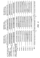
- Fig. 3 is a transformation table of standardization exposure energy and sub-dot data.
- a bit string is stated which is obtained by dividing the value of the standardization exposure energy es(k) stated on the second queue to the sub-lines 0 ⁇ 7.
- the sub-line 0 is provided with a weight factor of 1; the sub-line 1 is provided with a weight factor of 2; the sub-line 2 is provided with a weight factor of 4; the sub-line 3 is provided with a weight factor of 8; the sub-line 4 is provided with a weight factor of 16; the sub-line 5 is provided with a weight factor of 32; the sub-line 6 is provided with a weight factor of 64; and the sub-line 7 is provided with a weight factor of 128.
- the energy/lamp lighting pattern transforming section 35 according to the table (the value in the table is not added by random number), as an example, divides the random number addition standardization exposure energy es*(k) into 8-bits, and transforms them into sub-dot data corresponding to sub-dots formed on the 8 sub-lines.
- the sub-dot data server as the sub-dot data pdata [0] ⁇ [s-1] added random number, are sent out to the binary sub-line buffer group 36.
- the binary sub-line buffer group 36 has s binary sub-line buffers from f0 to fs-1, these buffers sequentially receive the sub-dot data pdata [0] ⁇ [s-1] from the energy/lamp lighting pattern transforming section 35, and store bit data of one main scanning line part.
- the data multiplexer 37 on the basis of an instruction of the sub-line counter 42, synchronously with clock signal CLK, reads out the sub-dot data of one sub-line, that are stored in the binary sub-line buffer group 36, and outputs them as data signal DATA to a shift register circuit 21.
- the dot timing producing circuit 38 is a circuit to make the sub-dot data shift synchronously with clock signal CLK.
- the line timing producing circuit 39 is a circuit to generate a latch signal LATCH and output it to a latch circuit 22.
- the strobe time register group 40 is a register group to previously store strobe times corresponding to the sub-lines 0 ⁇ s-1.
- the strobe time multiplexer 41 is a part to, read out predetermined strobe times stored in the strobe time register group 40 on the basis of an instruction of the sub-line counter 42 and send it to the strobe signal producing circuit 43.
- the sub-line counter 42 is a counter to orderly specify the sub-lines 0 ⁇ s-1.
- the strobe signal producing circuit 43 is a part to, on the basis of the strobe times received from the strobe time multiplexer 41, generate a strobe signal and send it to a driver circuit 23.
- the above-stated LED head 12 has a driver chip 14, a LED array 15 consisting of a plurality of LED elements, and a rod lens array 16 to converge the light emitted from the LED array 15 onto the surface of the photosensitive body drum 11. Further, the driver chip 14 has the shift register circuit 21, the latch circuit 22, and driver circuit 23.
- the shift register circuit 21 is a circuit to be synchronous with clock signal CLK generated by the dot timing producing circuit 38 and orderly receive the data signal DATA from the data multiplexer 37.
- the latch circuit 22 is a circuit for receiving sub-dot data of one sub-line part from the shift register circuit 21 to corresponding to the timing of latch signal LATCH produced by the line timing producing circuit 39.
- the driver circuit 23 is a circuit to receive the strobe signal STB from the strobe signal producing circuit 43, and during the strobe time corresponding to the sub-lines 0 ⁇ s-1, flow a strobe electricity to a gate on which the sub-dot data is at high level (1).
- Fig. 4 is a time chart of LED printer of embodiment 1.
- a n-bits gray scale value input from top to bottom, a n-bits gray scale value input; an output of gray scale value/energy transforming section 32; an output of random generator 34; an output of adding circuit 33; and an output of energy/lamp lighting pattern transforming section 35 from sub-line 1 to sub-line 7 are orderly shown.
- a time passage in a horizontal axis direction used in common for respective items is shown.
- n-bits gray scale value input (Fig. 2) is equal to the value stated in the Fig. 12.
- Fig. 5 is a diagram showing an output of random number generator.
- the output of the energy/lamp lighting pattern transforming section 35 is 8-bits data (according to the Fig. 3) corresponding to the sub-lines 0 ⁇ 7.
- the gray scale value/energy transforming section 32 receives the gray scale values (1, 1, 1, 1, 1, 1, 1, 1, 1) of line 1 according to a pixel order, and starts to transforms it into a standardization exposure energy es(k) on the basis of the relation shown by the Fig. 13.
- the standardization exposure energy es(k) is 63.
- the random generator 34 (Fig. 2) outputs 0 (Fig. 5).
- the random generator 34 (Fig. 2) outputs 0 (Fig. 5).
- the gray scale value/energy transforming section 32 receives the gray scale values (13, 13, 13, 13, 13, 13, 13, 13, 13) of line 5 according to a pixel order, and starts to transforms it into a standardization exposure energy es(k) on the basis of the relation shown by the Fig. 13.
- the random generator 34 (Fig. 2) outputs 1 (Fig. 5).
- the random generator 34 (Fig. 2) outputs 0 (Fig. 5).
- the random generator 34 (Fig. 2) outputs 0 during the time T38-time T40, so during the time T40-time T42, the energy/lamp lighting pattern transforming section 35, in the same way as the time T35, stores the pdata [0] ⁇ pdata [7] [00000011] to the corresponding binary sub-line buffers from f0 to f7.
- the gray scale value/energy transforming section 32 receives the gray scale values (1, 1, 1, 1, 1, 1, 1, 1, 1, 1) of line 9 according to a pixel order, and starts to transforms it into a standardization exposure energy es(k) on the basis of the relation shown by the Fig. 13.
- the standardization exposure energy es(k) is 63.
- the random generator 34 (Fig. 2) outputs 1 (Fig. 5).
- the random generator 34 (Fig. 2) outputs 1 during the time T53-time T55, so during the time T55 ⁇ time T57, the energy/lamp lighting pattern transforming section 35, in the same way as the time 54, stores the pdata [0] ⁇ pdata [7] [00000010] to the corresponding binary sub-line buffers from f0 to f7.
- the random generator 34 (Fig. 2) outputs 0 at the time T57, so at the time T59, the energy/lamp lighting pattern transforming section 35, in the same way as the time T58, stores the pdata [0] ⁇ pdata [7] [11111100] to the corresponding binary sub-line buffers from f0 to f7.
- Fig. 6 is an explanation diagram for explaining a gray scale pixel forming method of embodiment 1.
- the Fig. 6 is an image drawing when the values stored in the binary sub-line buffers from f0 to f7 in the above-stated operation explanation are outputted and printed.
- the Y-axis direction indicates an assistant scanning direction, on the most left queue, respective line numbers are shown; and the X-axis direction indicates an main scanning direction, on the highest row, respective pixel numbers on each line are shown.
- 8 sub-lines (0, 1, 2, 3, 4, 5, 6, 7) will be formed in the assistant scanning direction per 1/4800 inch.
- the standardization exposure energy es(k) of each pixel is divided into bit data of 8-bits, and they, as sub-dots, are respectively indicated on the 8 sub-lines (0, 1, 2, 3, 4, 5, 6, 7).
- a weight factor of 1 is set; in the sub-line 1, a weight factor of 2 is set; in the sub-line 2, a weight factor of 4 is set; in the sub-line 3, a weight factor of 8 is set; in the sub-line 4, a weight factor of 16 is set; in the sub-line 5, a weight factor of 32 is set; in the sub-line 6, a weight factor of 64 is set; and in the sub-line 7, a weight factor of 128 is set.
- one dot on the main scanning line is constructed by composing a plurality of sub-dot formed on plural sub-lines their positions are different in the assistant scanning direction.
- the composition of the sub-dots only the value of the standardization exposure energy es(k) is taken notice.
- the positions of the plurality of sub-dots in the assistant scanning direction are respectively different, therefore, according to the bit structure of the sub-dot, such case also possibly happens that: before and after the random number addition calculation, the center positions of the standardization exposure energy es(k) of the composed sub-dots become greatly different.
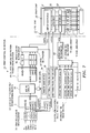
- Fig. 7 is a block diagram showing a print controlling section and a structure of LED head of embodiment 2.
- the print controlling section 53 includes a gray scale value input register 31, a gray scale value/energy transforming section 32, an adding circuit 33, a random generator 34, an energy/lamp lighting pattern transforming section 35, a binary sub-line buffer group 36, a data multiplexer 37, a dot timing producing circuit 38, a line timing producing circuit 39, a strobe time register group 40, a strobe time multiplexer 41, a sub-line counter 42, a strobe signal producing circuit 43, a modulation control selecting section 54, and an AND gate 55.
- the following is only to explain the part different from the embodiment 1 in detail. Regarding the same part as the embodiment 1, the same symbols are assigned and their explanations are omitted.
- the modulation control selecting section 54 is a part, with respect to a center position of the standardization exposure energy es(k) of composed sub-dots and a predetermined ideal center position, compares their difference quantities before and after the random number addition calculation, if the difference quantity after the random number addition calculation is bigger than the difference quantity before the random number addition calculation, stop the random number addition calculation for the gray scale value k.
- the modulation control selecting section 54 has a modulation control selection table for judging whether a random number addition calculation control with respect to the gray scale value k is suitable; if it is judged that the gray scale value k inputted from the gray scale value input register 31 is suitable for random number addition calculation control, sends a modulation control necessary signal (high level) to the AND gate 55; if it is judged that the gray scale value k inputted from the gray scale value input register 31 is not suitable for random number addition calculation control, sends a modulation control unnecessary signal to the AND gate 55.
- the following is to explain in detail the contents of the modulation control selection table.
- Fig. 8 is an explanation diagram of modulation control selecting table.
- the queue 54-1 shows a gray scale value k.
- the queue 54-2 shows a value of the standardization exposure energy es(k). The value is obtained to correspond to the gray scale value k, on the basis of the relation shown by above-stated Fig. 13.
- the queue 54-3 shows a center position Wk of energy of respective standardization exposure energy es(k)s in the assistant scanning direction.
- the numerical formula is well known and it is obtained by utilizing an expression to request a gravity center of a rigid body (Here, a center position of energy) having a predetermined partial density (Here, weight factor).
- the queue 54-5 shows a center position Wk* in the assistant scanning direction when the standardization exposure energy es(k)s is plussed 1 (es(k)+1).
- the center position Wk* is found as the above-stated Wk.
- the queue 54-6 shows a difference quantity (absolute value) of Wk on the basis of a predetermined ideal center position Wave (Here, as an example, it is set to 1.95), that is, shows
- the queue 54-7 shows a difference quantity (absolute value) of Wk* on the basis of a predetermined ideal center position Wave, i.e.
- the queue 54-8 shows whether the modulation control is necessary.
- the AND gate 55 is a gate which output +1 to the adding circuit 33 only when received +1 from both of the modulation control selecting section 54 and the random generator 34. Regarding other parts, because they are the same as the embodiment 1, so their explanation are omitted. The following is to explain operations of the embodiment 2 through a time chart.
- Fig. 9 is a time chart of LED printer of embodiment 2.
- a n-bits gray scale value input an output of gray scale value/energy transforming section 32; an output of random generator 34; an output of modulation control selecting section 54; an output of adding circuit 33; and an output of energy/lamp lighting pattern transforming section 35 from sub-line 1 to sub-line 7 are orderly shown.
- a time passage in a horizontal axis direction used in common for respective items is shown.
- Fig. 10 is an explanation diagram of inputted gray scale value (second).
- the Fig. 10 shows gray scale value of 4-bits received by the image forming apparatus in the embodiment 2 via the gray scale value inputting register.
- the Y-axis direction indicates an assistant scanning direction, on the most left queue, respective line numbers are shown; and the X-axis direction indicates an main scanning direction, on the highest row, respective pixel numbers on each line are shown; further, on each column, a gray scale value of pixel specified by the corresponding line number and the corresponding pixel number is stated.
- the Fig. 10 shows a case that gray scale values are orderly inputted to the gray scale value inputting register.
- the gray scale values (3, 3, 3, 3, 3, 3, 3, 3, 3) is inputted;
- the gray scale values (3, 3, 3, 3, 3, 3, 3, 3, 3) is inputted;
- the gray scale values (3, 3, 3, 3, 3, 3, 3, 3, 3) is inputted;
- the gray scale values (3, 3, 3, 3, 3, 3, 3, 3, 3) is inputted;
- at timing of line 4 the gray scale values (13, 13, 13, 13, 13, 13, 13, 13, 13, 13, 13) is inputted;
- at timing of line 5 the gray scale values (13, 13, 13, 13, 13, 13, 13, 13, 13, 13) is inputted;
- at timing of line 6 the gray scale values (13, 13, 13, 13, 13, 13, 13, 13, 13, 13) is inputted;
- at timing of line 7, the gray scale values (3, 3, 3, 3, 3, 3, 3, 3, 3, 3, 3) is inputted;
- the gray scale values (3, 3, 3, 3, 3, 3, 3, 3, 3, 3, 3) is inputted; and at timing of line 9, the
- n-bits gray scale value input (Fig. 7) is equal to the value stated in the Fig. 10.
- the modulation control selecting section 54 (Fig. 7) is to judge whether a modulation control is necessary on the basis of the modulation control selection table shown by the Fig. 8.
- the output of the energy/lamp lighting pattern transforming section 35 (Fig. 7) is 8-bits data (according to the Fig. 3) corresponding to the sub-lines 0 ⁇ 7.
- the gray scale value/energy transforming section 32 receives the gray scale values (3, 3, 3, 3, 3, 3, 3, 3, 3) of line 1 according to a pixel order, and starts to transforms it into a standardization exposure energy es(k) on the basis of the relation shown by the Fig. 13.
- the standardization exposure energy es(k) is 102.
- the modulation control selecting section 54 (Fig. 7) outputs a modulation control unnecessary signal (0) according to that the gray scale value k is 3.
- the random generator 34 (Fig. 7) outputs 0 (Fig. 5).
- the random generator 34 (Fig. 7) outputs 1 at the time T5 and at the time T9, but all outputs of the modulation control selecting section 54 (Fig. 7) are 0, so the energy/lamp lighting pattern transforming section 35 (Fig. 7), in the same way as the time 4, stores the pdata [0] ⁇ pdata [7] [01100110] to the corresponding binary sub-line buffers from f0 to f7.
- the gray scale value/energy transforming section 32 receives the gray scale values (13, 13, 13, 13, 13, 13, 13, 13, 13) of line 5 according to a pixel order, and starts to transforms it into a standardization exposure energy es(k) on the basis of the relation shown by the Fig. 13.
- the standardization exposure energy es(k) is 192.
- the random generator 34 (Fig. 7) outputs 1 (Fig. 5).
- the modulation control selecting section 54 (Fig. 7) outputs a modulation control necessary signal (1) according to that the gray scale value k is 13, further the random generator 34 (Fig. 7) outputs 1 during the time T34-time T37, so during the time T36-time T39, the energy/lamp lighting pattern transforming section 35 (Fig. 7), in the same way as the time T34, stores the pdata [0] ⁇ pdata [7] [10000011] to the corresponding binary sub-line buffers from f0 to f7.
- the modulation control selecting section 54 (Fig. 7) outputs a modulation control necessary signal (1) according to that the gray scale value k is 13, further the random generator 34 (Fig. 7) outputs 0 during the time T38-time T40, so during the time T40-time T42, the energy/lamp lighting pattern transforming section 35, in the same way as the time T35, stores the pdata [0] ⁇ pdata [7] [00000011] to the corresponding binary sub-line buffers from f0 to f7.
- the modulation control selecting section 54 (Fig. 7) outputs a modulation control necessary signal (1) according to that the gray scale value k is 13, further the random generator 34 (Fig. 7) outputs 1 at the time T41, so during the time T43, the energy/lamp lighting pattern transforming section 35, in the same way as the time T34, stores the pdata [0] ⁇ pdata [7] [10000011] to the corresponding binary sub-line buffers from f0 to f7.
- the gray scale value/energy transforming section 32 receives the gray scale values (3, 3, 3, 3, 3, 3, 3, 3, 3) of line 9 according to a pixel order, and starts to transforms it into a standardization exposure energy es(k) on the basis of the relation shown by the Fig. 13.
- the modulation control selecting section 54 (Fig. 7) outputs a modulation control unnecessary signal (0) according to that the gray scale value k is 3.
- the random generator 34 (Fig. 7) outputs 0 (Fig. 5).
- the modulation control selecting section 54 (Fig. 7) always outputs a modulation control unnecessary signal (0), so the energy/lamp lighting pattern transforming section 35, in the same way as the time 54, stores the pdata [0] ⁇ pdata [7] [01100110] to the corresponding binary sub-line buffers from f0 to f'7.
- Fig. 11 is an explanation diagram for explaining a gray scale pixel forming method of embodiment 2.
- the Fig. 11 is an image drawing when the values stored in the binary sub-line buffers from f0 to f7 in the above-stated operation explanation are outputted and printed.
- the Y-axis direction indicates an assistant scanning direction, on the most left queue, respective line numbers are shown; and the X-axis direction indicates an main scanning direction, on the highest row, respective pixel numbers on each line are shown.
- 8 sub-lines (0, 1, 2, 3, 4, 5, 6, 7) will be formed in the assistant scanning direction per 1/4800 inch.
- the standardization exposure energy es(k) of each pixel is divided into bit data of 8-bits, and they, as sub-dots, are respectively indicated on the 8 sub-lines (0, 1, 2,3,4,5,6,7).
- a weight factor of 1 is set; in the sub-line 1, a weight factor of 2 is set; in the sub-line 2, a weight factor of 4 is set; in the sub-line 3, a weight factor of 8 is set; in the sub-line 4, a weight factor of 16 is set; in the sub-line 5, a weight factor of 32 is set; in the sub-line 6, a weight factor of 64 is set; and in the sub-line 7, a weight factor of 128 is set.
Landscapes
- Engineering & Computer Science (AREA)
- Multimedia (AREA)
- Signal Processing (AREA)
- Printers Or Recording Devices Using Electromagnetic And Radiation Means (AREA)
- Image Processing (AREA)
- Fax Reproducing Arrangements (AREA)
- Facsimile Scanning Arrangements (AREA)
Applications Claiming Priority (1)
| Application Number | Priority Date | Filing Date | Title |
|---|---|---|---|
| JP2006055112A JP4842671B2 (ja) | 2006-03-01 | 2006-03-01 | 画像形成装置 |
Publications (2)
| Publication Number | Publication Date |
|---|---|
| EP1830554A2 true EP1830554A2 (de) | 2007-09-05 |
| EP1830554A3 EP1830554A3 (de) | 2008-05-21 |
Family
ID=38068518
Family Applications (1)
| Application Number | Title | Priority Date | Filing Date |
|---|---|---|---|
| EP07103047A Withdrawn EP1830554A3 (de) | 2006-03-01 | 2007-02-26 | Bilderzeugungsvorrichtung |
Country Status (4)
| Country | Link |
|---|---|
| US (1) | US7701613B2 (de) |
| EP (1) | EP1830554A3 (de) |
| JP (1) | JP4842671B2 (de) |
| CN (1) | CN101028768B (de) |
Family Cites Families (8)
| Publication number | Priority date | Publication date | Assignee | Title |
|---|---|---|---|---|
| JPH05244371A (ja) * | 1992-02-27 | 1993-09-21 | Canon Inc | 記録装置および方法 |
| JPH0664206A (ja) * | 1992-06-19 | 1994-03-08 | Fuji Xerox Co Ltd | 中間調記録用サーマルヘッド,中間調記録方法および中間調記録装置 |
| JPH11240201A (ja) * | 1998-02-25 | 1999-09-07 | Oki Data Corp | ノンインパクトプリンタ |
| JP3820819B2 (ja) * | 1999-11-09 | 2006-09-13 | 富士ゼロックス株式会社 | 画像形成装置 |
| JP2001265001A (ja) * | 2000-03-17 | 2001-09-28 | Fuji Photo Film Co Ltd | 画像記録装置および方法 |
| US7602411B2 (en) * | 2003-06-12 | 2009-10-13 | Oki Data Corporation | Image forming apparatus |
| JP4360543B2 (ja) * | 2003-06-12 | 2009-11-11 | 株式会社沖データ | 画像形成装置 |
| US7292260B2 (en) | 2003-09-24 | 2007-11-06 | Fujifilm Corporation | Image forming apparatus and image forming method |
-
2006
- 2006-03-01 JP JP2006055112A patent/JP4842671B2/ja not_active Expired - Fee Related
-
2007
- 2007-02-16 CN CN2007100858281A patent/CN101028768B/zh not_active Expired - Fee Related
- 2007-02-26 EP EP07103047A patent/EP1830554A3/de not_active Withdrawn
- 2007-02-26 US US11/678,820 patent/US7701613B2/en not_active Expired - Fee Related
Also Published As
| Publication number | Publication date |
|---|---|
| CN101028768B (zh) | 2011-02-23 |
| US20070206243A1 (en) | 2007-09-06 |
| CN101028768A (zh) | 2007-09-05 |
| EP1830554A3 (de) | 2008-05-21 |
| JP4842671B2 (ja) | 2011-12-21 |
| US7701613B2 (en) | 2010-04-20 |
| JP2007230095A (ja) | 2007-09-13 |
Similar Documents
| Publication | Publication Date | Title |
|---|---|---|
| EP3617805B1 (de) | Bilderzeugungsvorrichtung, verfahren zur steuerung davon und speichermedium | |
| JP4723663B2 (ja) | 画像形成方法 | |
| EP1835721A1 (de) | Bilderzeugungsvorrichtung | |
| US8294963B2 (en) | Image forming apparatus | |
| KR100659618B1 (ko) | 노광량 결정 방법 | |
| US8086059B2 (en) | Sub-raster registration using non-redundant overwriting | |
| US9195160B2 (en) | Image forming apparatus and image forming method for correcting registration deviation | |
| EP1830554A2 (de) | Bilderzeugungsvorrichtung | |
| JP4360543B2 (ja) | 画像形成装置 | |
| US6850340B1 (en) | Image data processing method and apparatus | |
| EP0416121B1 (de) | Drucker mit gradierter aufzeichnung | |
| US5583558A (en) | Recording apparatus for carrying out high-density dot printing | |
| US6825825B2 (en) | Smoothing method, smoothing circuit, image forming apparatus and display unit | |
| US20020167678A1 (en) | Image processing method, image processing equipment and image forming equipment | |
| US20250208556A1 (en) | Image forming apparatus and control method therefor, and storage medium | |
| CN119427952B (zh) | 打印方法、装置、电子设备、介质及产品 | |
| JP6531340B2 (ja) | 画像形成装置 | |
| JP2002369008A (ja) | 2値画像データの処理方法及びそれを利用した画像形成装置 | |
| US20170359486A1 (en) | Image forming apparatus, image forming method, and storage medium | |
| JP2000037908A (ja) | 画像形成装置 | |
| JP2003125201A (ja) | 階調表示方法 | |
| JP2002166597A (ja) | 光書き込みプリンタ | |
| JPH08174903A (ja) | 画像記録装置 | |
| JP2002057885A (ja) | 画像処理装置と画像処理方法 | |
| HK1013480B (en) | Line printer for high density printing |
Legal Events
| Date | Code | Title | Description |
|---|---|---|---|
| PUAI | Public reference made under article 153(3) epc to a published international application that has entered the european phase |
Free format text: ORIGINAL CODE: 0009012 |
|
| AK | Designated contracting states |
Kind code of ref document: A2 Designated state(s): AT BE BG CH CY CZ DE DK EE ES FI FR GB GR HU IE IS IT LI LT LU LV MC NL PL PT RO SE SI SK TR |
|
| AX | Request for extension of the european patent |
Extension state: AL BA HR MK YU |
|
| PUAL | Search report despatched |
Free format text: ORIGINAL CODE: 0009013 |
|
| AK | Designated contracting states |
Kind code of ref document: A3 Designated state(s): AT BE BG CH CY CZ DE DK EE ES FI FR GB GR HU IE IS IT LI LT LU LV MC NL PL PT RO SE SI SK TR |
|
| AX | Request for extension of the european patent |
Extension state: AL BA HR MK RS |
|
| AKX | Designation fees paid | ||
| 17P | Request for examination filed |
Effective date: 20080626 |
|
| RBV | Designated contracting states (corrected) |
Designated state(s): DE FR GB NL |
|
| 17Q | First examination report despatched |
Effective date: 20090304 |
|
| STAA | Information on the status of an ep patent application or granted ep patent |
Free format text: STATUS: THE APPLICATION IS DEEMED TO BE WITHDRAWN |
|
| 18D | Application deemed to be withdrawn |
Effective date: 20160705 |