EP1830141A1 - Air conditioner - Google Patents
Air conditioner Download PDFInfo
- Publication number
- EP1830141A1 EP1830141A1 EP07012490A EP07012490A EP1830141A1 EP 1830141 A1 EP1830141 A1 EP 1830141A1 EP 07012490 A EP07012490 A EP 07012490A EP 07012490 A EP07012490 A EP 07012490A EP 1830141 A1 EP1830141 A1 EP 1830141A1
- Authority
- EP
- European Patent Office
- Prior art keywords
- temperature
- refrigerant
- pipe
- target
- pressure corresponding
- Prior art date
- Legal status (The legal status is an assumption and is not a legal conclusion. Google has not performed a legal analysis and makes no representation as to the accuracy of the status listed.)
- Granted
Links
Images


Classifications
-
- F—MECHANICAL ENGINEERING; LIGHTING; HEATING; WEAPONS; BLASTING
- F25—REFRIGERATION OR COOLING; COMBINED HEATING AND REFRIGERATION SYSTEMS; HEAT PUMP SYSTEMS; MANUFACTURE OR STORAGE OF ICE; LIQUEFACTION SOLIDIFICATION OF GASES
- F25B—REFRIGERATION MACHINES, PLANTS OR SYSTEMS; COMBINED HEATING AND REFRIGERATION SYSTEMS; HEAT PUMP SYSTEMS
- F25B13/00—Compression machines, plants or systems, with reversible cycle
-
- F—MECHANICAL ENGINEERING; LIGHTING; HEATING; WEAPONS; BLASTING
- F25—REFRIGERATION OR COOLING; COMBINED HEATING AND REFRIGERATION SYSTEMS; HEAT PUMP SYSTEMS; MANUFACTURE OR STORAGE OF ICE; LIQUEFACTION SOLIDIFICATION OF GASES
- F25B—REFRIGERATION MACHINES, PLANTS OR SYSTEMS; COMBINED HEATING AND REFRIGERATION SYSTEMS; HEAT PUMP SYSTEMS
- F25B41/00—Fluid-circulation arrangements
- F25B41/20—Disposition of valves, e.g. of on-off valves or flow control valves
- F25B41/24—Arrangement of shut-off valves for disconnecting a part of the refrigerant cycle, e.g. an outdoor part
-
- F—MECHANICAL ENGINEERING; LIGHTING; HEATING; WEAPONS; BLASTING
- F25—REFRIGERATION OR COOLING; COMBINED HEATING AND REFRIGERATION SYSTEMS; HEAT PUMP SYSTEMS; MANUFACTURE OR STORAGE OF ICE; LIQUEFACTION SOLIDIFICATION OF GASES
- F25B—REFRIGERATION MACHINES, PLANTS OR SYSTEMS; COMBINED HEATING AND REFRIGERATION SYSTEMS; HEAT PUMP SYSTEMS
- F25B2313/00—Compression machines, plants or systems with reversible cycle not otherwise provided for
- F25B2313/023—Compression machines, plants or systems with reversible cycle not otherwise provided for using multiple indoor units
- F25B2313/0233—Compression machines, plants or systems with reversible cycle not otherwise provided for using multiple indoor units in parallel arrangements
-
- F—MECHANICAL ENGINEERING; LIGHTING; HEATING; WEAPONS; BLASTING
- F25—REFRIGERATION OR COOLING; COMBINED HEATING AND REFRIGERATION SYSTEMS; HEAT PUMP SYSTEMS; MANUFACTURE OR STORAGE OF ICE; LIQUEFACTION SOLIDIFICATION OF GASES
- F25B—REFRIGERATION MACHINES, PLANTS OR SYSTEMS; COMBINED HEATING AND REFRIGERATION SYSTEMS; HEAT PUMP SYSTEMS
- F25B2313/00—Compression machines, plants or systems with reversible cycle not otherwise provided for
- F25B2313/031—Sensor arrangements
- F25B2313/0314—Temperature sensors near the indoor heat exchanger
-
- F—MECHANICAL ENGINEERING; LIGHTING; HEATING; WEAPONS; BLASTING
- F25—REFRIGERATION OR COOLING; COMBINED HEATING AND REFRIGERATION SYSTEMS; HEAT PUMP SYSTEMS; MANUFACTURE OR STORAGE OF ICE; LIQUEFACTION SOLIDIFICATION OF GASES
- F25B—REFRIGERATION MACHINES, PLANTS OR SYSTEMS; COMBINED HEATING AND REFRIGERATION SYSTEMS; HEAT PUMP SYSTEMS
- F25B2313/00—Compression machines, plants or systems with reversible cycle not otherwise provided for
- F25B2313/031—Sensor arrangements
- F25B2313/0315—Temperature sensors near the outdoor heat exchanger
-
- F—MECHANICAL ENGINEERING; LIGHTING; HEATING; WEAPONS; BLASTING
- F25—REFRIGERATION OR COOLING; COMBINED HEATING AND REFRIGERATION SYSTEMS; HEAT PUMP SYSTEMS; MANUFACTURE OR STORAGE OF ICE; LIQUEFACTION SOLIDIFICATION OF GASES
- F25B—REFRIGERATION MACHINES, PLANTS OR SYSTEMS; COMBINED HEATING AND REFRIGERATION SYSTEMS; HEAT PUMP SYSTEMS
- F25B2400/00—General features or devices for refrigeration machines, plants or systems, combined heating and refrigeration systems or heat-pump systems, i.e. not limited to a particular subgroup of F25B
- F25B2400/16—Receivers
-
- F—MECHANICAL ENGINEERING; LIGHTING; HEATING; WEAPONS; BLASTING
- F25—REFRIGERATION OR COOLING; COMBINED HEATING AND REFRIGERATION SYSTEMS; HEAT PUMP SYSTEMS; MANUFACTURE OR STORAGE OF ICE; LIQUEFACTION SOLIDIFICATION OF GASES
- F25B—REFRIGERATION MACHINES, PLANTS OR SYSTEMS; COMBINED HEATING AND REFRIGERATION SYSTEMS; HEAT PUMP SYSTEMS
- F25B2600/00—Control issues
- F25B2600/02—Compressor control
- F25B2600/024—Compressor control by controlling the electric parameters, e.g. current or voltage
-
- F—MECHANICAL ENGINEERING; LIGHTING; HEATING; WEAPONS; BLASTING
- F25—REFRIGERATION OR COOLING; COMBINED HEATING AND REFRIGERATION SYSTEMS; HEAT PUMP SYSTEMS; MANUFACTURE OR STORAGE OF ICE; LIQUEFACTION SOLIDIFICATION OF GASES
- F25B—REFRIGERATION MACHINES, PLANTS OR SYSTEMS; COMBINED HEATING AND REFRIGERATION SYSTEMS; HEAT PUMP SYSTEMS
- F25B2600/00—Control issues
- F25B2600/05—Refrigerant levels
-
- F—MECHANICAL ENGINEERING; LIGHTING; HEATING; WEAPONS; BLASTING
- F25—REFRIGERATION OR COOLING; COMBINED HEATING AND REFRIGERATION SYSTEMS; HEAT PUMP SYSTEMS; MANUFACTURE OR STORAGE OF ICE; LIQUEFACTION SOLIDIFICATION OF GASES
- F25B—REFRIGERATION MACHINES, PLANTS OR SYSTEMS; COMBINED HEATING AND REFRIGERATION SYSTEMS; HEAT PUMP SYSTEMS
- F25B2700/00—Sensing or detecting of parameters; Sensors therefor
- F25B2700/15—Power, e.g. by voltage or current
- F25B2700/151—Power, e.g. by voltage or current of the compressor motor
-
- F—MECHANICAL ENGINEERING; LIGHTING; HEATING; WEAPONS; BLASTING
- F25—REFRIGERATION OR COOLING; COMBINED HEATING AND REFRIGERATION SYSTEMS; HEAT PUMP SYSTEMS; MANUFACTURE OR STORAGE OF ICE; LIQUEFACTION SOLIDIFICATION OF GASES
- F25B—REFRIGERATION MACHINES, PLANTS OR SYSTEMS; COMBINED HEATING AND REFRIGERATION SYSTEMS; HEAT PUMP SYSTEMS
- F25B2700/00—Sensing or detecting of parameters; Sensors therefor
- F25B2700/19—Pressures
- F25B2700/193—Pressures of the compressor
- F25B2700/1931—Discharge pressures
-
- F—MECHANICAL ENGINEERING; LIGHTING; HEATING; WEAPONS; BLASTING
- F25—REFRIGERATION OR COOLING; COMBINED HEATING AND REFRIGERATION SYSTEMS; HEAT PUMP SYSTEMS; MANUFACTURE OR STORAGE OF ICE; LIQUEFACTION SOLIDIFICATION OF GASES
- F25B—REFRIGERATION MACHINES, PLANTS OR SYSTEMS; COMBINED HEATING AND REFRIGERATION SYSTEMS; HEAT PUMP SYSTEMS
- F25B2700/00—Sensing or detecting of parameters; Sensors therefor
- F25B2700/19—Pressures
- F25B2700/193—Pressures of the compressor
- F25B2700/1933—Suction pressures
-
- F—MECHANICAL ENGINEERING; LIGHTING; HEATING; WEAPONS; BLASTING
- F25—REFRIGERATION OR COOLING; COMBINED HEATING AND REFRIGERATION SYSTEMS; HEAT PUMP SYSTEMS; MANUFACTURE OR STORAGE OF ICE; LIQUEFACTION SOLIDIFICATION OF GASES
- F25B—REFRIGERATION MACHINES, PLANTS OR SYSTEMS; COMBINED HEATING AND REFRIGERATION SYSTEMS; HEAT PUMP SYSTEMS
- F25B2700/00—Sensing or detecting of parameters; Sensors therefor
- F25B2700/19—Pressures
- F25B2700/195—Pressures of the condenser
-
- F—MECHANICAL ENGINEERING; LIGHTING; HEATING; WEAPONS; BLASTING
- F25—REFRIGERATION OR COOLING; COMBINED HEATING AND REFRIGERATION SYSTEMS; HEAT PUMP SYSTEMS; MANUFACTURE OR STORAGE OF ICE; LIQUEFACTION SOLIDIFICATION OF GASES
- F25B—REFRIGERATION MACHINES, PLANTS OR SYSTEMS; COMBINED HEATING AND REFRIGERATION SYSTEMS; HEAT PUMP SYSTEMS
- F25B2700/00—Sensing or detecting of parameters; Sensors therefor
- F25B2700/21—Temperatures
- F25B2700/2106—Temperatures of fresh outdoor air
-
- F—MECHANICAL ENGINEERING; LIGHTING; HEATING; WEAPONS; BLASTING
- F25—REFRIGERATION OR COOLING; COMBINED HEATING AND REFRIGERATION SYSTEMS; HEAT PUMP SYSTEMS; MANUFACTURE OR STORAGE OF ICE; LIQUEFACTION SOLIDIFICATION OF GASES
- F25B—REFRIGERATION MACHINES, PLANTS OR SYSTEMS; COMBINED HEATING AND REFRIGERATION SYSTEMS; HEAT PUMP SYSTEMS
- F25B2700/00—Sensing or detecting of parameters; Sensors therefor
- F25B2700/21—Temperatures
- F25B2700/2115—Temperatures of a compressor or the drive means therefor
- F25B2700/21152—Temperatures of a compressor or the drive means therefor at the discharge side of the compressor
-
- F—MECHANICAL ENGINEERING; LIGHTING; HEATING; WEAPONS; BLASTING
- F25—REFRIGERATION OR COOLING; COMBINED HEATING AND REFRIGERATION SYSTEMS; HEAT PUMP SYSTEMS; MANUFACTURE OR STORAGE OF ICE; LIQUEFACTION SOLIDIFICATION OF GASES
- F25B—REFRIGERATION MACHINES, PLANTS OR SYSTEMS; COMBINED HEATING AND REFRIGERATION SYSTEMS; HEAT PUMP SYSTEMS
- F25B45/00—Arrangements for charging or discharging refrigerant
-
- F—MECHANICAL ENGINEERING; LIGHTING; HEATING; WEAPONS; BLASTING
- F25—REFRIGERATION OR COOLING; COMBINED HEATING AND REFRIGERATION SYSTEMS; HEAT PUMP SYSTEMS; MANUFACTURE OR STORAGE OF ICE; LIQUEFACTION SOLIDIFICATION OF GASES
- F25B—REFRIGERATION MACHINES, PLANTS OR SYSTEMS; COMBINED HEATING AND REFRIGERATION SYSTEMS; HEAT PUMP SYSTEMS
- F25B49/00—Arrangement or mounting of control or safety devices
- F25B49/02—Arrangement or mounting of control or safety devices for compression type machines, plants or systems
Definitions
- the present invention relates to an air conditioner, and particularly to an air conditioner provided with a receiver for collecting surplus refrigerant.
- a refrigerant circuit of an air conditioner is formed of a refrigerant pipe structure connecting an accumulator, a compressor, a four-way valve and an outdoor heat exchanger, which are arranged in an outdoor unit, as well as an indoor heat exchanger arranged in an indoor unit, and provides a circulation path of refrigerant.
- the dour-way valve controls a refrigerant circulating direction such that the outdoor heat exchanger functions as a condenser, and the indoor heat exchanger functions as an evaporator.
- the four-way valve controls the refrigerant circulating direction such that the outdoor heat exchanger functions as an evaporator, and the indoor heat exchanger functions as a condenser.
- the refrigerant circuit on the outdoor unit side is filled with an appropriate amount of refrigerant containing an additional amount of refrigerant, which is required for a connection pipe of a maximum length.
- the appropriate amount of refrigerant, which is required during an operation significantly changes depending on an operation mode, a capacity of the indoor unit and a length of the connection pipe used for actual installation. Therefore, surplus refrigerant may be present in the refrigerant circuit, and this may cause abnormal rising of a pressure when it remains in the condenser, and may lower the operation efficiency.
- a receiver In a conventional receiver circuit, a receiver is arranged in a pipe portion on a liquid pipe side between the outdoor heat exchanger and the liquid shut-off valve, and is located in series thereto. Therefore, the amount of refrigerant in the receiver increases or decreases merely in accordance with a degree of opening of a motor-operated valve located downstream from the receiver.
- This motor-operated value corresponds to each room motor-operated value in a cooling operation, and corresponds to a main pressure reducing value, and the degree of opening thereof is controlled based on a degree of super-heating.
- the outdoor heat exchanger when a cooling operation is performed when the outside-air temperature is extremely low, the outdoor heat exchanger has an excessively large capacity so that the pressure on the high-pressure side lowers. Therefore, a difference between the high and low pressures of the compressor decreases, which lowers reliability of the compressor. If the surplus refrigerant, which is collected in the receiver, can be transferred to the outdoor heat exchanger, a portion of the outdoor heat exchanger can be filled with the surplus refrigerant. Thereby, the capacity of the outdoor heat exchanger lowers, and the pressure on the high-pressure side rises so that a sufficient pressure difference can be ensured.
- An object of the invention is to control surplus refrigerant in accordance with operation situations such as a cooling operation at a lower outside-air temperature and an operation with an excessive load.
- An air conditioner includes a refrigerant circuit formed of an outdoor unit refrigerant circuit including at least a compressor, a four-way valve and an outdoor heat exchanger arranged in an outdoor unit, and an indoor heat exchanger arranged in an indoor unit and connected to the outdoor unit refrigerant circuit by a liquid-side pipe and a gas-side pipe.
- a bypass circuit forming a bypass between the liquid-side and gas-side pipes is provided with a receiver for collecting liquid refrigerant, and refrigerant on-off means arranged in a liquid pipe connection pipe connecting the receiver to the liquid-side pipe and in a gas pipe connection pipe connecting the receiver to the gas-side pipe.
- the refrigerant on-off means is controlled based on determination of presence/absence of surplus refrigerant performed by determining a current heat exchanging performance of the outdoor heat exchanger, and thereby an amount of the refrigerant in the receiver is controlled.
- the refrigerant on-off means may be formed of a liquid pipe motor-operated value arranged in the liquid-side pipe and being capable of controlling a flow rate of the refrigerant, and a gas pipe motor-operated valve arranged in the gas pipe connection pipe and being capable of controlling a flow rate of the refrigerant.
- the presence/absence of the surplus refrigerant is determined by making a comparison between an outlet temperature of the outdoor heat exchanger and a target value of the outlet temperature of the outdoor heat exchanger.
- a detected value of an outdoor liquid pipe thermistor arranged at the vicinity of the outlet of the outdoor heat exchanger may be used as the outlet temperature of the outdoor heat exchanger.
- the air conditioner may be configured such that, in a cooling operation, the target value of the outlet temperature of the outdoor heat exchanger is determined from an amount of circulated refrigerant and an outside-air temperature, or is determined from an operation frequency of the compressor and the outside-air temperature.
- the target value of the outlet temperature of the outdoor heat exchanger may be corrected based on a deviation in super-heat control or target discharge pipe temperature control.
- the target value of the outlet temperature of the outdoor heat exchanger may be equal to or lower than a higher one between a high-pressure saturation temperature and a heat exchange intermediate temperature of the outdoor heat exchanger, and may be equal to or higher than a sum of a current outside-air temperature and a predetermined temperature.
- the air conditioner may be configured such that the liquid pipe motor-operated valve operates in the cooling operation to open when the outlet temperature of the outdoor heat exchanger is lower than the target temperature, and to close when the outlet temperature of the outdoor heat exchanger is higher than the target temperature.
- the presence/absence of the surplus refrigerant may be determined in the cooling operation by comparing a high-pressure corresponding saturation temperature with a target value of the high-pressure corresponding saturation temperature.
- the air conditioner thus configured may further include a high-pressure sensor arranged on a discharge side of the compressor for high-pressure protection, and the high-pressure corresponding saturation temperature may be calculated from a high-pressure value detected by the high-pressure sensor.
- a pressure on an intake side of the compressor, power consumption of the compressor and an operation frequency of the compressor may be used for calculating the high-pressure corresponding saturation temperature.
- the target temperature of the high-pressure corresponding saturation temperature may be determined from an amount of circulated refrigerant and an outside-air temperature, or may be determined from an operation frequency of the compressor and the outside-air temperature.
- the target value of the high-pressure corresponding saturation temperature may be corrected based on a deviation in super-heat control or target discharge pipe temperature control.
- the target value of the high-pressure corresponding saturation temperature may be equal to or lower than a sum of a high-pressure saturation temperature and a predetermined value, and may be equal to or higher than a sum of a current outside-air temperature and a predetermined temperature.
- the air conditioner may be configured such that the liquid pipe motor-operated valve operates in the cooling operation to close when the high-pressure corresponding saturation temperature is lower than the target temperature, and to open when the high-pressure corresponding saturation temperature is higher than the target temperature.
- the presence/absence of the surplus refrigerant may be determined in the heating operation by comparing a representative value of the liquid pipe temperature with a target value of the liquid-pipe temperature.
- the representative value of the liquid pipe temperature may be a lowest value of the liquid pipe temperature of the indoor unit during an operation.
- the target temperature of the liquid pipe temperature may be determined from an amount of circulated refrigerant and a room temperature, or may be determined from an operation frequency of the compressor and the room temperature.
- the target value of the liquid pipe temperature may be corrected based on a deviation in super-heat control or target discharge pipe temperature control.
- the target value of the liquid pipe temperature may be equal to or lower than a higher one between a high-pressure saturation temperature and a maximum value of a heat exchange intermediate temperature of the indoor heat exchanger, and may be equal to or higher than a sum of a maximum value of a room temperature and a predetermined value.
- the air conditioner may be configured such that the gas pipe motor-operated valve operates in the heating operation to open when a representative value of the liquid pipe temperature is lower than the target temperature, and to close when a representative value of the liquid pipe temperature is higher than the target temperature.
- the presence/absence of the surplus refrigerant may be determined in the heating operation by comparing a high-pressure corresponding saturation temperature with a target value of the high-pressure corresponding saturation temperature.
- the target temperature of the high-pressure corresponding saturation temperature may be determined from an amount of circulated refrigerant and a room temperature, or may be determined from an operation frequency of the compressor and the room temperature.
- the target value of the high-pressure corresponding saturation temperature may be corrected based on a deviation in super-heat control or target discharge pipe temperature control.
- the target value of the high-pressure corresponding saturation temperature may be equal to or lower than a sum of a high-pressure saturation temperature and a predetermined value, and may be equal to or higher than a sum of a room temperature and a predetermined value.
- the air conditioner may be configured such that the gas pipe motor-operated valve operates in the heating operation to open when the high-pressure corresponding saturation temperature is lower than the target temperature, and to close when the high-pressure corresponding saturation temperature is higher than the target temperature.
- An air conditioner employing a first embodiment of the invention has a refrigerant circuit shown in Fig. 1.
- An outdoor unit 100 includes an outdoor refrigerant circuit provided with a compressor 101, a four-way valve 102, an outdoor heat exchanger 103 and an accumulator 105.
- a discharge-side pressure protection switch 108 is arranged on the discharge side of the compressor 101 for detecting abnormal rising of the discharge pressure.
- An intake-side pressure sensor 110 is arranged on the intake side of the compressor 101 for detecting an intake pressure.
- An oil separator 107 is arranged on the discharge side of the compressor 101 for separating and returning lubricating oil contained in the refrigerant to the accumulator 105.
- the oil separator 107 is provided with a discharge pipe thermistor 109 for detecting a temperature on the discharge side of the compressor 101.
- An oil return pie 197 of the oil separator 107 is provided with a discharge bypass circuit 194, which is branched from the oil return pipe 197, and is connected to an inlet side of the accumulator 105.
- This discharge bypass circuit 194 is provided with a heat exchanger pipe portion 196 arranged within the accumulator 105 and a discharge-intake motor-operated valve 142 for capacity control.
- the oil return pipe 197 of the oil separator 107 is provided with a capillary 141, which is also connected to the intake side of the accumulator 105.
- the outdoor unit 100 is also provided with an outside-air thermistor 111 for detecting an outside-air temperature, an outdoor heat exchange thermistor 112 for detecting an outlet temperature of the outdoor heat exchanger 103, and an heat exchange intermediate thermistor 113 for detecting an heat exchanger intermediate temperature.
- the outdoor unit 100 is further provided with a fan 106 for performing heat exchange between the outside air taken into the unit 100 and the refrigerant flowing within the outdoor heat exchanger 103, and a fan motor 104 for driving the fan 106.
- the refrigerant pipe extending from the outdoor unit 100 toward the indoor unit is provided with a liquid pipe connection port 114 connected to the outdoor heat exchanger 103, and a gas pipe connection port 115 connected to the outdoor heat exchanger 103 via the four-way valve 102.
- the ports 114 and 115 are internally provided with a liquid pipe shut-off valve 116 and a gas pipe shut-off valve 117, respectively.
- the outdoor unit 100 includes a receiver 121 for temporarily storing surplus refrigerant liquid, which flows from the outdoor heat exchanger 103 serving as a condenser in the cooling operation.
- the receiver 121 is provided with a liquid pipe connection pipe 122 and a gas pipe connection pipe 123.
- the liquid pipe connection pipe 122 is connected to a liquid-side pipe portion 131 between the outdoor heat exchanger 103 and the liquid pipe shut-off valve 116.
- the gas pipe connection pipe 123 is connected to a gas-side pipe portion 132 between the four-way valve 102 and the gas pipe shut-off valve 117.
- the liquid pipe connection pipe 122 of the receiver 121 is provided with a liquid pipe motor-operated valve (EVL) 128 having a pressure reducing function and a refrigerant shut-off function.
- the gas pipe connection pipe 123 is provided with a gas pipe motor-operated valve (EVG) 129.
- An auxiliary heat exchanger 133 is arranged between the gas pipe motor-operated valve 129 and a connection to the gas-side pipe portion 132.
- a sub-cool heat exchanger 134 is arranged in a liquid-side outlet of the outdoor heat exchanger 103.
- a gas vent capillary 130 is directed toward a portion of the gas-side pipe portion 132 between the four-way valve 102 and the gas pipe shut-off valve 117 for collecting a refrigerant gas from the receiver 121.
- branch units 300A, 300B, ⁇ are connected to each of the liquid pipe connection port 114 and the gas pipe connection port 115 of the outdoor unit 100. Since these branch units 300A, 300B, ⁇ have the same structures, the description will now be given on only the branch unit 300A, and the others will not be described.
- the branch unit 300A includes an outdoor side liquid pipe connection port 301 connected to the liquid pipe connection port 114 of the outdoor unit 100 and an indoor side gas pipe connection port 303 connected to the gas pipe connection port 115 of the outdoor unit 100.
- the branch unit 300A has liquid-side branches divided within the outdoor side connection port 301, and ends of these branches form a plurality of indoor side liquid pipe connection ports 302 equal in number to the indoor units connected thereto.
- the branch unit 300A also has gas-side branches divided within the outdoor side gas pipe connection port 303, and ends of these branches form indoor side gas pipe connection ports 304 equal in number to the indoor units connected thereto.
- indoor units connected to the ports are three in number, and indoor side liquid pipe connection ports 302A, 302B and 302C as well as indoor side gas pipe connection ports 304A, 304B and 304C are employed.
- a motor-operated valve 308 for bypass is arranged between the outdoor side liquid pipe connection port 301 and the outdoor side gas pipe connection port 303.
- the branches which extend from the outdoor side liquid pipe connection port 301 within the branch unit 300A to the indoor side liquid pipe connection ports 302A - 302C, respectively, are provided with motor-operated valves 305A - 305C for reducing the pressures of the refrigerant flowing therethrough as well as liquid pipe thermistors 306A - 306C for detecting temperatures of the refrigerant flowing therethrough, respectively.
- the branches which extend from the outdoor side gas pipe connection port 303 within the branch unit 300A to the indoor side gas pipe connection ports 304A - 304C, respectively, are provided with gas pipe thermistors 307A - 307C for detecting the temperatures of the refrigerant flowing therethrough, respectively.
- Each of the branch units 300A, 300B, ⁇ is connected to a plurality of outdoor units 200. It is assumed in the structure shown in Fig. 1 that three outdoor units can be connected to each of the branch units 300A, 300B, ••• so that outdoor units 200A - 200C are connected to the branch unit 300A, and outdoor units 200D - 200F are connected to the branch unit 300B.
- Each of the indoor units 200A - 200F can be used in the indoor unit of either a multi-unit type or a pair-unit type. In the following description, the indoor unit 200A is of the pair-unit type.
- the indoor unit 200A is provided with an indoor heat exchanger 201, which is connected to a refrigerant pipe extending toward the outdoor unit through a liquid pipe connection port 204 and a gas pipe connection port 205.
- the indoor unit 200A is provided with a room temperature thermistor 202 for detecting a room temperature and an indoor heat exchange thermistor 203 for detecting a temperature of the indoor heat exchanger 201.
- the liquid-side pipe portion may be provided with a liquid pipe thermistor for detecting the temperature of the refrigerant flowing therethrough, in which case the liquid pipe thermistors in the branch units 300A and 300B may be eliminated.
- the surplus refrigerant is controlled in accordance with a liquid pipe temperature. This will be described below with reference to a flowchart of Fig. 2.
- a step S11 it is determined whether a surplus refrigerant control sampling time TSCSET has elapsed or not.
- the processing moves to a step S12.
- the target liquid pipe temperature is calculated.
- a variable DOATD is calculated in accordance with the following formula using target liquid pipe temperature calculation coefficients KSCC1, KSCC2, KSCC3 and EDOSC, a target frequency EMK of the compressor 101, a discharge pipe temperature deviation EDO and others.
- DOATD KSCC ⁇ 1 ⁇ FMK + KSCC ⁇ 2 - ( EDO - EDOSC ) ⁇ KSCC ⁇ 3
- a step S22 it is determined whether the variable DOATD is larger than a lower limit DOATDMIN of the target liquid pipe temperature or not.
- the processing moves to a step S23.
- the value of variable DOATD is set to the lower limit DOATDMIN of the target liquid pipe temperature.
- a step S24 it is determined whether the variable DOATD is equal to or smaller than ((upper limit DOATDMAX of target liquid pipe temperature) - (outside air temperature DOA)) or not.
- the processing moves to a step S25.
- the value of variable DOATD is set to ((upper limit DOATDMAX of target liquid pipe temperature) - (outside air temperature DOA)).
- a target liquid pipe temperature DELSET is calculated.
- DELSET DOA outside air temperature + DOATD variable
- a liquid pipe temperature deviation ⁇ DEL is calculated from the target liquid pipe temperature DELSET and the outdoor heat exchanger outlet temperature DEL in accordance with the following formula.
- ⁇ DEL DELSET - DEL
- step S14 processing is performed to calculate an amount or degree, by which the motor-operated valve is to be operated.
- a motor-operated valve operation amount POSC is calculated in accordance with the following formula using coefficients KOSCA1 and KOSCA, which are coefficients for calculating the motor-operated valve operation amount, the liquid pipe temperature deviation ⁇ DEL, the last liquid pipe temperature deviation ⁇ DELZ and others.
- KOSCA1 and KOSCA coefficients for calculating the motor-operated valve operation amount, the liquid pipe temperature deviation ⁇ DEL, the last liquid pipe temperature deviation ⁇ DELZ and others.
- a step S15 the motor-operated valve is operated in accordance with the operation amount determined in the step S14.
- a degree EVL of opening of the liquid pipe motor-operated valve 128 is defined by ((current degree EVL) + (motor-operated valve operation amount POSC)).
- a degree EVG of opening of the gas pipe motor-operated valve 129 is controlled to attain ((current degree EVG) + (operation amount POSC) x KPOSC1).
- the liquid pipe temperature during the cooling operation can be determined from a value detected by the outdoor heat exchange thermistor 112 arranged at the vicinity of the outlet of the outdoor heat exchanger 103. Based on the liquid pipe temperature, it is possible to control the amount of the surplus refrigerant in the receiver 121.
- the amount of the surplus refrigerant is controlled to ensure a difference between high and low pressures in the compressor 101.
- a step S51 it is determined whether a surplus refrigerant control sampling time TSCSET has elapsed or not.
- the processing moves to a step S52.
- the target high-pressure corresponding saturation temperature is calculated.
- the variable DOATD is calculated in accordance with the following formula using the target high-pressure corresponding saturation temperature calculation coefficients KSCC1, KSCC2, KSCC3 and EDOSC, the target frequency FMK of the compressor 101, the discharge pipe temperature deviation EDO and others.
- DOATD KSCC ⁇ 1 ⁇ FMK + KSCC ⁇ 2 - EDO - EDOSC ⁇ KSCC ⁇ 3
- a step S62 it is determined whether the variable DOATD is larger than a lower limit DOATDMIN of the target high-pressure corresponding saturation temperature or not.
- the processing moves to a step S63.
- the value of variable DOATD is set to the lower limit DOATDMIN of the target high-pressure corresponding saturation temperature.
- a step S64 it is determined whether the variable DOATD is equal to or smaller than the upper limit DOATDMAX of the target high-pressure corresponding saturation temperature or not.
- the processing moves to a step S65.
- the value of variable DOATD is set to the upper limit DOATDMAX of the target high-pressure corresponding saturation temperature.
- a step S66 the target high-pressure corresponding saturation temperature TDSSET is calculated.
- TDSSET DOA ( outside air temperature ) + DOATD variable
- a high-pressure corresponding saturation temperature deviation ⁇ TDS is calculated from the high-pressure corresponding saturation temperature TDSSET and the target high-pressure corresponding saturation temperature TDSSET TDS in accordance with the following formula.
- ⁇ TDS TDSSET - TDS
- a step S54 processing is performed to calculate an amount or degree, by which the motor-operated valve is to be operated.
- the motor-operated valve operation amount POSC is calculated in accordance with the following formula using the coefficients KOSCA1 and KOSCA, which are coefficients for calculating the motor-operated valve operation amount, the high-pressure corresponding saturation temperature deviation ⁇ TDS, the last high-pressure corresponding saturation temperature deviation ⁇ TDSZ and others.
- KOSCA1 and KOSCA coefficients for calculating the motor-operated valve operation amount, the high-pressure corresponding saturation temperature deviation ⁇ TDS, the last high-pressure corresponding saturation temperature deviation ⁇ TDSZ and others.
- a step S55 the motor-operated valve is operated in accordance with the operation amount determined in the step S54.
- the degree EVL of opening of the liquid pipe motor-operated valve 128 is defined by ((current degree EVL) + (motor-operated valve operation amount POSC)).
- the degree EVG of opening of the gas pipe motor-operated valve 129 is controlled to attain ((current degree EVG) + (operation amount POSC) x KPOSC1).
- a step S91 it is determined whether a surplus refrigerant control sampling time TSCSET has elapsed or not.
- the processing moves to a step S92.
- the target liquid pipe temperature is calculated.
- the variable DOATD is calculated in accordance with the following formula using target liquid pipe temperature calculation coefficients KSCC1 and KSCC2, the target frequency FMK of the compressor 101 and others.
- DOATD KSCC ⁇ 1 ⁇ FMK + KSCC ⁇ 2
- a step S102 it is determined whether the variable DOATD is larger than the lower limit DOATDMIN of the target liquid pipe temperature or not.
- the processing moves to a step S103.
- the value of variable DOATD is set to the lower limit DOATDMIN of the target liquid pipe temperature.
- a step S104 it is determined whether the variable DOATD is equal to or smaller than ((upper limit DOATDMAX of target liquid pipe temperature) - room temperature DA) or not.
- the processing moves to a step S105.
- the value of variable DOATD is set to ((upper limit DOATDMAX of target liquid pipe temperature) - room temperature DA) .
- a target liquid pipe temperature DLSET is calculated.
- the following formula is employed for this calculation.
- DLSET DA room temperature + DOATD variable
- a liquid pipe temperature deviation ⁇ DL is calculated.
- step S94 processing is performed to calculate an amount or degree, by which the motor-operated valve is to be operated.
- the motor-operated valve operation amount POSC is calculated in accordance with the following formula using the coefficients KOSCA1 and KOSCA, which are coefficients for calculating the motor-operated valve operation amount, the liquid pipe temperature deviation ⁇ DL, the last liquid pipe temperature deviation ⁇ DLZ and others.
- KOSCA1 and KOSCA coefficients for calculating the motor-operated valve operation amount, the liquid pipe temperature deviation ⁇ DL, the last liquid pipe temperature deviation ⁇ DLZ and others.
- a step S95 the motor-operated valve is operated in accordance with the operation amount determined in the step S94.
- the degree EVG of opening of the gas pipe motor-operated valve 129 is defined by ((current degree EVG) + (motor-operated valve operation amount POSC)).
- the degree EVL of opening of the liquid pipe motor-operated valve 128 is controlled to attain ((current degree EVL) + (operation amount POSC) x KPOSC1) .
- the lowest liquid pipe temperature in the indoor unit 200, which is being operating, is used as the representative value of the liquid pipe temperature, and the amount of the surplus refrigerant in the receiver 121 can be controlled with this representative value of the liquid pipe temperature.
- a step S131 it is determined whether a surplus refrigerant control sampling time TSCSET has elapsed or not.
- the processing moves to a step S132.
- the target high-pressure corresponding saturation temperature is calculated.
- a step S142 it is determined whether the variable DOATD is larger than the lower limit DOATIMIN of the target high-pressure corresponding saturation temperature or not.
- the processing moves to a step S143.
- the value of variable DOATD is set to the lower limit DOATDMIN of the target high-pressure corresponding saturation temperature.
- a step S144 it is determined whether the variable DOATD is equal to or smaller than the upper limit DOATDMAX of the target high-pressure corresponding saturation temperature or not.
- the processing moves to a step S145.
- the value of variable DOATD is set to the upper limit DOATDMAX of the target high-pressure corresponding saturation temperature.
- a target high-pressure corresponding saturation temperature TDSSET is calculated.
- TDSSET DA room temperature + DOATD variable
- a step S133 the high-pressure corresponding saturation temperature deviation ⁇ TDS is calculated.
- the high-pressure corresponding saturation temperature deviation ⁇ TDS is calculated from the high-pressure corresponding saturation temperature TDS and the target high-pressure corresponding saturation temperature TDSSET in accordance with the following formula.
- ⁇ TDS TDSSET - TDS
- a step S134 processing is performed to calculate an amount or degree, by which the motor-operated valve is to be operated.
- the motor-operated valve operation amount POSC is calculated in accordance with the following formula using the coefficients KOSCA1 and KOSCA, which are coefficients for calculating the motor-operated valve operation amount, the high-pressure corresponding saturation temperature deviation ⁇ TDS, the last high-pressure corresponding saturation temperature deviation ⁇ TDSZ and others.
- KOSCA1 and KOSCA coefficients for calculating the motor-operated valve operation amount, the high-pressure corresponding saturation temperature deviation ⁇ TDS, the last high-pressure corresponding saturation temperature deviation ⁇ TDSZ and others.
- step S135 the motor-operated valve is operated in accordance with the operation amount determined in the step S134.
- the degree EVG of opening of the gas pipe motor-operated valve 129 is defined by ((current degree EVG) + (motor-operated valve operation amount POSC)).
- the degree EVL of opening of the liquid pipe motor-operated valve 128 is controlled to attain ((current degree EVL) + (operation amount POSC) x KPOSC1).
- a control portion 501 is formed of a microprocessor including a CPU, a ROM, a RAM and others, and is connected to a ROM 502 storing an operation control program and various parameters as well as a RAM 503 for temporarily storing work variables.
- the control portion 501 is also connected to various sensor elements including the intake-side pressure sensor 110, discharge pipe thermistor 109, outside air thermistor 111, outdoor heat exchange thermistor 112 and heat exchange intermediate thermistor 113, which are arranged within an outdoor unit 100, for receiving values detected by these sensor and thermistors. Further, the discharge-side pressure switch 108 is connected to the control portion 501.
- An indoor-side communication interface 504 for transmitting various data between the indoor unit 200 and the branch unit 300 is connected to the control portion 501.
- control portion 501 is connected to a compressor drive circuit 505 for controlling the operation frequency of the compressor 101 and a fan motor drive circuit 506 for controlling a frequency of the fan motor 104.
- the control portion 501 is further connected to the liquid and gas pipe motor-operated valves 128 and 129 arranged on the opposite sides of the receiver 121, and the discharge-intake motor-operated valve 142 arranged on the discharge bypass circuit 194 of the compressor 101.
- the compressor drive circuit 505 is provided with an active filter circuit, which will be described later, and a secondary voltage sensor 507 and a secondary current sensor 508 of the active filter circuit are connected to the control portion 501.
- Fig. 19 is a block diagram showing control of the compressor drive circuit 505 in Fig. 18.
- the compressor drive circuit 505 includes a rectifier circuit 512 connected to a commercial power supply 511, an active filter circuit 513 and an inverter circuit 514.
- the rectifier circuit 512 is formed of a diode bridge including four diodes, and performs full-wave rectification on an AC power supplied from the commercial power supply 511.
- the active filter circuit 513 includes a reactor 521, a diode 522, a capacitor 523, a switching element 524 and active filter drive means 525 for performing switching control of the switching element 524.
- the active filter 513 includes a primary voltage sensor 526 for detecting a primary voltage, a primary current sensor 527 for detecting a primary current, a secondary voltage sensor 507 for detecting a secondary voltage and a secondary current sensor 508 for detecting a secondary current.
- the active filter drive means 525 performs the switching control on the switching element 524 so that the secondary voltage detected by the secondary voltage sensor 507 may become equal to a predetermined voltage.
- the active filter drive means 525 controls the current value detected by the primary current sensor 527 so that it matches in phase with the primary voltage detected by the primary voltage sensor 526. This significantly increases a power factor, and thus increases the accuracy of calculating the power consumption based on the secondary voltage detected by the secondary voltage sensor 507 and the secondary current detected by the secondary current sensor 508.
- the inverter circuit 514 produces a pulse signal of a constant voltage from an output signal of a predetermined voltage sent from the active filter circuit 513.
- the output frequency of the inverter circuit 514 in this operation is equal to the operation frequency of the compressor determined based on the current operation situations. Therefore, the compressor drive motor 531 is driven in accordance with the output frequency of the inverter circuit 514.
- the power consumption of the compressor 101 is calculated from the secondary voltage value and the secondary current value of the active filter 513 of the compressor drive circuit 505, and a value of the high-pressure corresponding temperature is estimated based on the power consumption thus calculated. A manner for this estimation will now be described with reference to a flowchart of Fig. 20.
- an input voltage VIN and an input current IIN applied to the inverter circuit 514 are detected.
- the input voltage VIN and the input current IIN applied to the inverter circuit 514 can be obtained from the secondary voltage sensor 507 and the secondary current sensor 508, which detect the secondary voltage and current of the active filter 513, respectively.
- a step S173 processing is performed to determine an output frequency FOUT for driving the compressor 101 as well as an intake pressure value LP thereof.
- the output frequency FOUT can be specifically determined from the output frequency of the inverter 514 driving the compressor drive motor 531.
- the intake pressure value LP can be specifically determined from the detected value of the intake pressure sensor 110.
- a high pressure value is determined based on the power consumption INPUT, output frequency FOUT and intake pressure value LP. This determination is performed in accordance with the following formula, which uses high pressure estimation constants KHPLL, KHPFF, KHPII, KHPLF, KHPFI, KHPLI, KHPL, KHPF, KHPI and KHPC as well as a high pressure correction value HPHOSEI.
- HP KHPLL ⁇ LP 2 + KHPFF ⁇ FOUT 2 + KHPII ⁇ INPUT 2 + KHPLF ⁇ LP ⁇ FOUT + KHPFI ⁇ FOUT ⁇ INPUT + KHPLI ⁇ LP ⁇ INPUT + KHPL ⁇ LP + KHPF ⁇ FOUT + KHPI ⁇ INPUT + KHPC + HPHOSEI
- the amount of surplus refrigerant collected into the receiver can be controlled in accordance with operation situations, and the degree of super cooling or super heating within the outdoor heat exchanger can be controlled. Therefore, an appropriate amount of refrigerant can be used in the refrigerant circuit system for performing efficient driving.
Abstract
Description
- The present invention relates to an air conditioner, and particularly to an air conditioner provided with a receiver for collecting surplus refrigerant.
- A refrigerant circuit of an air conditioner is formed of a refrigerant pipe structure connecting an accumulator, a compressor, a four-way valve and an outdoor heat exchanger, which are arranged in an outdoor unit, as well as an indoor heat exchanger arranged in an indoor unit, and provides a circulation path of refrigerant.
- When the refrigerant circuit of the air conditioner operate for cooling, the dour-way valve controls a refrigerant circulating direction such that the outdoor heat exchanger functions as a condenser, and the indoor heat exchanger functions as an evaporator. In a heating operation, the four-way valve controls the refrigerant circulating direction such that the outdoor heat exchanger functions as an evaporator, and the indoor heat exchanger functions as a condenser.
- In the above air conditioner, it is desired in view of ease of installation that the refrigerant circuit on the outdoor unit side is filled with an appropriate amount of refrigerant containing an additional amount of refrigerant, which is required for a connection pipe of a maximum length. However, the appropriate amount of refrigerant, which is required during an operation, significantly changes depending on an operation mode, a capacity of the indoor unit and a length of the connection pipe used for actual installation. Therefore, surplus refrigerant may be present in the refrigerant circuit, and this may cause abnormal rising of a pressure when it remains in the condenser, and may lower the operation efficiency.
- For deal with such surplus refrigerant, it has been proposed to arrange a receiver between the outdoor heat exchanger and a liquid shut-off valve for collecting the surplus refrigerant.
- In a conventional receiver circuit, a receiver is arranged in a pipe portion on a liquid pipe side between the outdoor heat exchanger and the liquid shut-off valve, and is located in series thereto. Therefore, the amount of refrigerant in the receiver increases or decreases merely in accordance with a degree of opening of a motor-operated valve located downstream from the receiver. This motor-operated value corresponds to each room motor-operated value in a cooling operation, and corresponds to a main pressure reducing value, and the degree of opening thereof is controlled based on a degree of super-heating. Therefore, it is difficult to control or adjust precisely the amount of liquid refrigerant in the receiver, and particularly, it is impossible to control the amount of liquid refrigerant in the receiver when a special operation such as an operation with a low outside-air temperature or with an excessive load.
- For example, when a cooling operation is performed when the outside-air temperature is extremely low, the outdoor heat exchanger has an excessively large capacity so that the pressure on the high-pressure side lowers. Therefore, a difference between the high and low pressures of the compressor decreases, which lowers reliability of the compressor. If the surplus refrigerant, which is collected in the receiver, can be transferred to the outdoor heat exchanger, a portion of the outdoor heat exchanger can be filled with the surplus refrigerant. Thereby, the capacity of the outdoor heat exchanger lowers, and the pressure on the high-pressure side rises so that a sufficient pressure difference can be ensured.
- An object of the invention is to control surplus refrigerant in accordance with operation situations such as a cooling operation at a lower outside-air temperature and an operation with an excessive load.
- An air conditioner according to the invention includes a refrigerant circuit formed of an outdoor unit refrigerant circuit including at least a compressor, a four-way valve and an outdoor heat exchanger arranged in an outdoor unit, and an indoor heat exchanger arranged in an indoor unit and connected to the outdoor unit refrigerant circuit by a liquid-side pipe and a gas-side pipe. A bypass circuit forming a bypass between the liquid-side and gas-side pipes is provided with a receiver for collecting liquid refrigerant, and refrigerant on-off means arranged in a liquid pipe connection pipe connecting the receiver to the liquid-side pipe and in a gas pipe connection pipe connecting the receiver to the gas-side pipe. The refrigerant on-off means is controlled based on determination of presence/absence of surplus refrigerant performed by determining a current heat exchanging performance of the outdoor heat exchanger, and thereby an amount of the refrigerant in the receiver is controlled.
- In the above structure, the refrigerant on-off means may be formed of a liquid pipe motor-operated value arranged in the liquid-side pipe and being capable of controlling a flow rate of the refrigerant, and a gas pipe motor-operated valve arranged in the gas pipe connection pipe and being capable of controlling a flow rate of the refrigerant.
- The presence/absence of the surplus refrigerant is determined by making a comparison between an outlet temperature of the outdoor heat exchanger and a target value of the outlet temperature of the outdoor heat exchanger.
- A detected value of an outdoor liquid pipe thermistor arranged at the vicinity of the outlet of the outdoor heat exchanger may be used as the outlet temperature of the outdoor heat exchanger.
- The air conditioner may be configured such that, in a cooling operation, the target value of the outlet temperature of the outdoor heat exchanger is determined from an amount of circulated refrigerant and an outside-air temperature, or is determined from an operation frequency of the compressor and the outside-air temperature.
- The target value of the outlet temperature of the outdoor heat exchanger may be corrected based on a deviation in super-heat control or target discharge pipe temperature control.
- The target value of the outlet temperature of the outdoor heat exchanger may be equal to or lower than a higher one between a high-pressure saturation temperature and a heat exchange intermediate temperature of the outdoor heat exchanger, and may be equal to or higher than a sum of a current outside-air temperature and a predetermined temperature.
- Further, the air conditioner may be configured such that the liquid pipe motor-operated valve operates in the cooling operation to open when the outlet temperature of the outdoor heat exchanger is lower than the target temperature, and to close when the outlet temperature of the outdoor heat exchanger is higher than the target temperature.
- The presence/absence of the surplus refrigerant may be determined in the cooling operation by comparing a high-pressure corresponding saturation temperature with a target value of the high-pressure corresponding saturation temperature.
- The air conditioner thus configured may further include a high-pressure sensor arranged on a discharge side of the compressor for high-pressure protection, and the high-pressure corresponding saturation temperature may be calculated from a high-pressure value detected by the high-pressure sensor.
- A pressure on an intake side of the compressor, power consumption of the compressor and an operation frequency of the compressor may be used for calculating the high-pressure corresponding saturation temperature.
- In the cooling operation, the target temperature of the high-pressure corresponding saturation temperature may be determined from an amount of circulated refrigerant and an outside-air temperature, or may be determined from an operation frequency of the compressor and the outside-air temperature.
- The target value of the high-pressure corresponding saturation temperature may be corrected based on a deviation in super-heat control or target discharge pipe temperature control.
- The target value of the high-pressure corresponding saturation temperature may be equal to or lower than a sum of a high-pressure saturation temperature and a predetermined value, and may be equal to or higher than a sum of a current outside-air temperature and a predetermined temperature.
- Further, the air conditioner may be configured such that the liquid pipe motor-operated valve operates in the cooling operation to close when the high-pressure corresponding saturation temperature is lower than the target temperature, and to open when the high-pressure corresponding saturation temperature is higher than the target temperature.
- The presence/absence of the surplus refrigerant may be determined in the heating operation by comparing a representative value of the liquid pipe temperature with a target value of the liquid-pipe temperature.
- In this case, the representative value of the liquid pipe temperature may be a lowest value of the liquid pipe temperature of the indoor unit during an operation.
- In the heating operation, the target temperature of the liquid pipe temperature may be determined from an amount of circulated refrigerant and a room temperature, or may be determined from an operation frequency of the compressor and the room temperature.
- The target value of the liquid pipe temperature may be corrected based on a deviation in super-heat control or target discharge pipe temperature control.
- The target value of the liquid pipe temperature may be equal to or lower than a higher one between a high-pressure saturation temperature and a maximum value of a heat exchange intermediate temperature of the indoor heat exchanger, and may be equal to or higher than a sum of a maximum value of a room temperature and a predetermined value.
- Further, the air conditioner may be configured such that the gas pipe motor-operated valve operates in the heating operation to open when a representative value of the liquid pipe temperature is lower than the target temperature, and to close when a representative value of the liquid pipe temperature is higher than the target temperature.
- The presence/absence of the surplus refrigerant may be determined in the heating operation by comparing a high-pressure corresponding saturation temperature with a target value of the high-pressure corresponding saturation temperature.
- In the heating operation, the target temperature of the high-pressure corresponding saturation temperature may be determined from an amount of circulated refrigerant and a room temperature, or may be determined from an operation frequency of the compressor and the room temperature.
- The target value of the high-pressure corresponding saturation temperature may be corrected based on a deviation in super-heat control or target discharge pipe temperature control.
- The target value of the high-pressure corresponding saturation temperature may be equal to or lower than a sum of a high-pressure saturation temperature and a predetermined value, and may be equal to or higher than a sum of a room temperature and a predetermined value.
- Further, the air conditioner may be configured such that the gas pipe motor-operated valve operates in the heating operation to open when the high-pressure corresponding saturation temperature is lower than the target temperature, and to close when the high-pressure corresponding saturation temperature is higher than the target temperature.
-
- Fig. 1 schematically shows a refrigerant circuit of an air conditioner employing an embodiment of the invention;
- Figs. 2 to 5 are control flowcharts of the first embodiment, respectively;
- Figs. 6 to 9 are control flowcharts of a second embodiment, respectively;
- Figs. 10 to 13 are control flowcharts of a third embodiment, respectively;
- Figs. 14 to 17 are control flowcharts of a fourth embodiment, respectively;
- Fig. 18 is a control block diagram of an embodiment;
- Fig. 19 is a control block diagram of a compressor drive circuit;
- Fig. 20 is a flowchart showing a manner of estimating a high-pressure corresponding saturation temperature; and
- Fig. 21 shows a table for calculating a saturation temperature.
- An air conditioner employing a first embodiment of the invention has a refrigerant circuit shown in Fig. 1.
- An
outdoor unit 100 includes an outdoor refrigerant circuit provided with acompressor 101, a four-way valve 102, anoutdoor heat exchanger 103 and anaccumulator 105. A discharge-sidepressure protection switch 108 is arranged on the discharge side of thecompressor 101 for detecting abnormal rising of the discharge pressure. An intake-side pressure sensor 110 is arranged on the intake side of thecompressor 101 for detecting an intake pressure. - An
oil separator 107 is arranged on the discharge side of thecompressor 101 for separating and returning lubricating oil contained in the refrigerant to theaccumulator 105. Theoil separator 107 is provided with adischarge pipe thermistor 109 for detecting a temperature on the discharge side of thecompressor 101. - An
oil return pie 197 of theoil separator 107 is provided with adischarge bypass circuit 194, which is branched from theoil return pipe 197, and is connected to an inlet side of theaccumulator 105. Thisdischarge bypass circuit 194 is provided with a heatexchanger pipe portion 196 arranged within theaccumulator 105 and a discharge-intake motor-operatedvalve 142 for capacity control. Theoil return pipe 197 of theoil separator 107 is provided with a capillary 141, which is also connected to the intake side of theaccumulator 105. - The
outdoor unit 100 is also provided with an outside-air thermistor 111 for detecting an outside-air temperature, an outdoorheat exchange thermistor 112 for detecting an outlet temperature of theoutdoor heat exchanger 103, and an heat exchange intermediate thermistor 113 for detecting an heat exchanger intermediate temperature. Theoutdoor unit 100 is further provided with afan 106 for performing heat exchange between the outside air taken into theunit 100 and the refrigerant flowing within theoutdoor heat exchanger 103, and afan motor 104 for driving thefan 106. - The refrigerant pipe extending from the
outdoor unit 100 toward the indoor unit is provided with a liquidpipe connection port 114 connected to theoutdoor heat exchanger 103, and a gaspipe connection port 115 connected to theoutdoor heat exchanger 103 via the four-way valve 102. Theports valve 116 and a gas pipe shut-offvalve 117, respectively. - The
outdoor unit 100 includes areceiver 121 for temporarily storing surplus refrigerant liquid, which flows from theoutdoor heat exchanger 103 serving as a condenser in the cooling operation. Thereceiver 121 is provided with a liquidpipe connection pipe 122 and a gaspipe connection pipe 123. The liquidpipe connection pipe 122 is connected to a liquid-side pipe portion 131 between theoutdoor heat exchanger 103 and the liquid pipe shut-offvalve 116. The gaspipe connection pipe 123 is connected to a gas-side pipe portion 132 between the four-way valve 102 and the gas pipe shut-offvalve 117. - The liquid
pipe connection pipe 122 of thereceiver 121 is provided with a liquid pipe motor-operated valve (EVL) 128 having a pressure reducing function and a refrigerant shut-off function. The gaspipe connection pipe 123 is provided with a gas pipe motor-operated valve (EVG) 129. - An
auxiliary heat exchanger 133 is arranged between the gas pipe motor-operatedvalve 129 and a connection to the gas-side pipe portion 132. Asub-cool heat exchanger 134 is arranged in a liquid-side outlet of theoutdoor heat exchanger 103. - A
gas vent capillary 130 is directed toward a portion of the gas-side pipe portion 132 between the four-way valve 102 and the gas pipe shut-offvalve 117 for collecting a refrigerant gas from thereceiver 121. - A plurality of
branch units pipe connection port 114 and the gaspipe connection port 115 of theoutdoor unit 100. Since thesebranch units branch unit 300A, and the others will not be described. - The
branch unit 300A includes an outdoor side liquidpipe connection port 301 connected to the liquidpipe connection port 114 of theoutdoor unit 100 and an indoor side gaspipe connection port 303 connected to the gaspipe connection port 115 of theoutdoor unit 100. Thebranch unit 300A has liquid-side branches divided within the outdoorside connection port 301, and ends of these branches form a plurality of indoor side liquid pipe connection ports 302 equal in number to the indoor units connected thereto. Thebranch unit 300A also has gas-side branches divided within the outdoor side gaspipe connection port 303, and ends of these branches form indoor side gas pipe connection ports 304 equal in number to the indoor units connected thereto. In the following description, it is assumed that the indoor units connected to the ports are three in number, and indoor side liquidpipe connection ports pipe connection ports valve 308 for bypass is arranged between the outdoor side liquidpipe connection port 301 and the outdoor side gaspipe connection port 303. - The branches, which extend from the outdoor side liquid
pipe connection port 301 within thebranch unit 300A to the indoor side liquidpipe connection ports 302A - 302C, respectively, are provided with motor-operatedvalves 305A - 305C for reducing the pressures of the refrigerant flowing therethrough as well asliquid pipe thermistors 306A - 306C for detecting temperatures of the refrigerant flowing therethrough, respectively. The branches, which extend from the outdoor side gaspipe connection port 303 within thebranch unit 300A to the indoor side gaspipe connection ports 304A - 304C, respectively, are provided withgas pipe thermistors 307A - 307C for detecting the temperatures of the refrigerant flowing therethrough, respectively. - Each of the
branch units branch units outdoor units 200A - 200C are connected to thebranch unit 300A, andoutdoor units 200D - 200F are connected to thebranch unit 300B. Each of theindoor units 200A - 200F can be used in the indoor unit of either a multi-unit type or a pair-unit type. In the following description, theindoor unit 200A is of the pair-unit type. - The
indoor unit 200A is provided with anindoor heat exchanger 201, which is connected to a refrigerant pipe extending toward the outdoor unit through a liquidpipe connection port 204 and a gaspipe connection port 205. Theindoor unit 200A is provided with aroom temperature thermistor 202 for detecting a room temperature and an indoorheat exchange thermistor 203 for detecting a temperature of theindoor heat exchanger 201. - If the indoor units connected to the
branch units branch units - In the cooling operation, the surplus refrigerant is controlled in accordance with a liquid pipe temperature. This will be described below with reference to a flowchart of Fig. 2.
- In a step S11, it is determined whether a surplus refrigerant control sampling time TSCSET has elapsed or not. When it is determined that an elapsed time counted by a timer has reached the surplus refrigerant control sampling time TSCSET, the processing moves to a step S12.
- In the step S12, the target liquid pipe temperature is calculated.
- The processing of calculating the target liquid pipe temperature will now be described with reference to a flowchart of Fig. 3.
- In a step S21, a variable DOATD is calculated in accordance with the following formula using target liquid pipe temperature calculation coefficients KSCC1, KSCC2, KSCC3 and EDOSC, a target frequency EMK of the
compressor 101, a discharge pipe temperature deviation EDO and others.
- In a step S22, it is determined whether the variable DOATD is larger than a lower limit DOATDMIN of the target liquid pipe temperature or not. When it is determined that the variable DOATD is not larger than the lower limit DOATDMIN of the target liquid pipe temperature, the processing moves to a step S23. In the step S23, the value of variable DOATD is set to the lower limit DOATDMIN of the target liquid pipe temperature.
- In a step S24, it is determined whether the variable DOATD is equal to or smaller than ((upper limit DOATDMAX of target liquid pipe temperature) - (outside air temperature DOA)) or not. When it is determined that the variable DOATD is larger than ((upper limit DOATDMAX of target liquid pipe temperature) - (outside air temperature DOA) ), the processing moves to a step S25. In the step S25, the value of variable DOATD is set to ((upper limit DOATDMAX of target liquid pipe temperature) - (outside air temperature DOA)).
- In a step S26, a target liquid pipe temperature DELSET is calculated. In this embodiment, the following formula is employed for this calculation.

- In a step S13, a liquid pipe temperature deviation ΔDEL is calculated from the target liquid pipe temperature DELSET and the outdoor heat exchanger outlet temperature DEL in accordance with the following formula.

- In a step S14, processing is performed to calculate an amount or degree, by which the motor-operated valve is to be operated.
- This processing of calculating the motor-operated valve operation amount is shown in a flowchart of Fig. 4.
- In a step S31, a motor-operated valve operation amount POSC is calculated in accordance with the following formula using coefficients KOSCA1 and KOSCA, which are coefficients for calculating the motor-operated valve operation amount, the liquid pipe temperature deviation ΔDEL, the last liquid pipe temperature deviation ΔDELZ and others.

- In a step S15, the motor-operated valve is operated in accordance with the operation amount determined in the step S14.
- Processing of operating the motor-operated valve is shown in a flowchart of Fig. 5.
- It is assumed that a degree EVL of opening of the liquid pipe motor-operated
valve 128 is defined by ((current degree EVL) + (motor-operated valve operation amount POSC)). At the same time, a degree EVG of opening of the gas pipe motor-operatedvalve 129 is controlled to attain ((current degree EVG) + (operation amount POSC) x KPOSC1). - The liquid pipe temperature during the cooling operation can be determined from a value detected by the outdoor
heat exchange thermistor 112 arranged at the vicinity of the outlet of theoutdoor heat exchanger 103. Based on the liquid pipe temperature, it is possible to control the amount of the surplus refrigerant in thereceiver 121. - Therefore, even when the cooling operation is performed while an outside-air temperature is low, the amount of the surplus refrigerant is controlled to ensure a difference between high and low pressures in the
compressor 101. - Referring to a flowchart of Fig. 6, description will now be given on control of surplus refrigerant performed with a high-pressure corresponding saturation temperature in the cooling operation. It is assumed that the same refrigerant circuit as that in the first embodiment is used for controlling the surplus refrigerant in the cooling operation.
- In a step S51, it is determined whether a surplus refrigerant control sampling time TSCSET has elapsed or not. When it is determined that an elapsed time counted by the timer has reached the surplus refrigerant control sampling time TSCSET, the processing moves to a step S52.
- In the step S52, the target high-pressure corresponding saturation temperature is calculated.
- The processing of calculating the target high-pressure corresponding saturation temperature will now be described with reference to a flowchart of Fig. 7.
- In a step S61, the variable DOATD is calculated in accordance with the following formula using the target high-pressure corresponding saturation temperature calculation coefficients KSCC1, KSCC2, KSCC3 and EDOSC, the target frequency FMK of the
compressor 101, the discharge pipe temperature deviation EDO and others.
- In a step S62, it is determined whether the variable DOATD is larger than a lower limit DOATDMIN of the target high-pressure corresponding saturation temperature or not. When it is determined that the variable DOATD is not larger than the lower limit DOATDMIN of the target high-pressure corresponding saturation temperature, the processing moves to a step S63. In the step S63, the value of variable DOATD is set to the lower limit DOATDMIN of the target high-pressure corresponding saturation temperature.
- In a step S64, it is determined whether the variable DOATD is equal to or smaller than the upper limit DOATDMAX of the target high-pressure corresponding saturation temperature or not. When it is determined that the variable DOATD is larger than the upper limit DOATDMAX of the target high-pressure corresponding saturation temperature, the processing moves to a step S65. In the step S65, the value of variable DOATD is set to the upper limit DOATDMAX of the target high-pressure corresponding saturation temperature.
- In a step S66, the target high-pressure corresponding saturation temperature TDSSET is calculated. In this embodiment, the following formula is employed for this calculation.

- In a step S53, a high-pressure corresponding saturation temperature deviation ΔTDS is calculated from the high-pressure corresponding saturation temperature TDSSET and the target high-pressure corresponding saturation temperature TDSSET TDS in accordance with the following formula.

- In a step S54, processing is performed to calculate an amount or degree, by which the motor-operated valve is to be operated.
- This processing of calculating the motor-operated valve operation amount is shown in a flowchart of Fig. 8.
- In a step S71, the motor-operated valve operation amount POSC is calculated in accordance with the following formula using the coefficients KOSCA1 and KOSCA, which are coefficients for calculating the motor-operated valve operation amount, the high-pressure corresponding saturation temperature deviation ΔTDS, the last high-pressure corresponding saturation temperature deviation ΔTDSZ and others.

- In a step S55, the motor-operated valve is operated in accordance with the operation amount determined in the step S54.
- Processing of operating the motor-operated valve is shown in a flowchart of Fig. 9.
- It is assumed that the degree EVL of opening of the liquid pipe motor-operated
valve 128 is defined by ((current degree EVL) + (motor-operated valve operation amount POSC)). At the same time, the degree EVG of opening of the gas pipe motor-operatedvalve 129 is controlled to attain ((current degree EVG) + (operation amount POSC) x KPOSC1). - Referring to a flowchart of Fig. 10, description will now be given on control of surplus refrigerant performed with a liquid pipe temperature in the heating operation.
- In a step S91, it is determined whether a surplus refrigerant control sampling time TSCSET has elapsed or not. When it is determined that an elapsed time counted by the timer has reached the surplus refrigerant control sampling time TSCSET, the processing moves to a step S92.
- In the step S92, the target liquid pipe temperature is calculated.
- The processing of calculating the target liquid pipe temperature will now be described with reference to a flowchart of Fig. 11.
- In a step S101, the variable DOATD is calculated in accordance with the following formula using target liquid pipe temperature calculation coefficients KSCC1 and KSCC2, the target frequency FMK of the
compressor 101 and others.
- In a step S102, it is determined whether the variable DOATD is larger than the lower limit DOATDMIN of the target liquid pipe temperature or not. When it is determined that the variable DOATD is not larger than the lower limit DOATDMIN of the target liquid pipe temperature, the processing moves to a step S103. In the step S103, the value of variable DOATD is set to the lower limit DOATDMIN of the target liquid pipe temperature.
- In a step S104, it is determined whether the variable DOATD is equal to or smaller than ((upper limit DOATDMAX of target liquid pipe temperature) - room temperature DA) or not. When it is determined that the variable DOATD is larger than ((upper limit DOATEMAX of target liquid pipe temperature) - room temperature DA), the processing moves to a step S105. In the step S105, the value of variable DOATD is set to ((upper limit DOATDMAX of target liquid pipe temperature) - room temperature DA) .
- In a step S106, a target liquid pipe temperature DLSET is calculated. In this embodiment, the following formula is employed for this calculation.

- In a step S93, a liquid pipe temperature deviation ΔDL is calculated. For the
indoor heat exchanger 201 having the lowest liquid pipe temperature in the indoor unit 200, which is operating, the liquid pipe temperature deviation ΔDL is calculated from a representative value DL of the liquid pipe temperature and the target liquid pipe temperature DLSET in accordance with the following formula.
- In a step S94, processing is performed to calculate an amount or degree, by which the motor-operated valve is to be operated.
- This processing of calculating the motor-operated valve operation amount is shown in a flowchart of Fig. 12.
- In a step S111, the motor-operated valve operation amount POSC is calculated in accordance with the following formula using the coefficients KOSCA1 and KOSCA, which are coefficients for calculating the motor-operated valve operation amount, the liquid pipe temperature deviation ΔDL, the last liquid pipe temperature deviation ΔDLZ and others.

- In a step S95, the motor-operated valve is operated in accordance with the operation amount determined in the step S94.
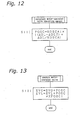
- Processing of operating the motor-operated valve is shown in a flowchart of Fig. 13.
- It is assumed that the degree EVG of opening of the gas pipe motor-operated
valve 129 is defined by ((current degree EVG) + (motor-operated valve operation amount POSC)). Likewise, the degree EVL of opening of the liquid pipe motor-operatedvalve 128 is controlled to attain ((current degree EVL) + (operation amount POSC) x KPOSC1) . - In the heating operation, the lowest liquid pipe temperature in the indoor unit 200, which is being operating, is used as the representative value of the liquid pipe temperature, and the amount of the surplus refrigerant in the
receiver 121 can be controlled with this representative value of the liquid pipe temperature. - Referring to a flowchart of Fig. 14, description will now be given on control of surplus refrigerant performed with a high-pressure corresponding saturation temperature in the heating operation.
- In a step S131, it is determined whether a surplus refrigerant control sampling time TSCSET has elapsed or not. When it is determined that an elapsed time counted by the timer has reached the surplus refrigerant control sampling time TSCSET, the processing moves to a step S132.
- In the step S132, the target high-pressure corresponding saturation temperature is calculated.
- The processing of calculating the target high-pressure corresponding saturation temperature will now be described with reference to a flowchart of Fig. 15.
- In a step S141, the variable DOATD is calculated in accordance with the following formula using the target high-pressure corresponding saturation temperature calculation coefficients KSCC1 and KSCC2, the target frequency FMK of the
compressor 101 and others.
- In a step S142, it is determined whether the variable DOATD is larger than the lower limit DOATIMIN of the target high-pressure corresponding saturation temperature or not. When it is determined that the variable DOATD is not larger than the lower limit DOATDMIN of the target high-pressure corresponding saturation temperature, the processing moves to a step S143. In the step S143, the value of variable DOATD is set to the lower limit DOATDMIN of the target high-pressure corresponding saturation temperature.
- In a step S144, it is determined whether the variable DOATD is equal to or smaller than the upper limit DOATDMAX of the target high-pressure corresponding saturation temperature or not. When it is determined that the variable DOATD is larger than the upper limit DOATDMAX of the target high-pressure corresponding saturation temperature, the processing moves to a step S145. In the step S145, the value of variable DOATD is set to the upper limit DOATDMAX of the target high-pressure corresponding saturation temperature.
- In a step S146, a target high-pressure corresponding saturation temperature TDSSET is calculated. In this embodiment, the following formula is employed for this calculation.

- In a step S133, the high-pressure corresponding saturation temperature deviation ΔTDS is calculated. The high-pressure corresponding saturation temperature deviation ΔTDS is calculated from the high-pressure corresponding saturation temperature TDS and the target high-pressure corresponding saturation temperature TDSSET in accordance with the following formula.

- In a step S134, processing is performed to calculate an amount or degree, by which the motor-operated valve is to be operated.
- This processing of calculating the motor-operated valve operation amount is shown in a flowchart of Fig. 16.
- In a step S151, the motor-operated valve operation amount POSC is calculated in accordance with the following formula using the coefficients KOSCA1 and KOSCA, which are coefficients for calculating the motor-operated valve operation amount, the high-pressure corresponding saturation temperature deviation ΔTDS, the last high-pressure corresponding saturation temperature deviation ΔTDSZ and others.

- In a step S135, the motor-operated valve is operated in accordance with the operation amount determined in the step S134.
- Processing of operating the motor-operated valve is shown in a flowchart of Fig. 17.
- It is assumed that the degree EVG of opening of the gas pipe motor-operated
valve 129 is defined by ((current degree EVG) + (motor-operated valve operation amount POSC)). Likewise, the degree EVL of opening of the liquid pipe motor-operatedvalve 128 is controlled to attain ((current degree EVL) + (operation amount POSC) x KPOSC1). - Description will now be given on a manner of estimating the high-pressure corresponding saturation temperature in the second embodiment already described. A control block for this estimation is shown in Fig. 18.
- A
control portion 501 is formed of a microprocessor including a CPU, a ROM, a RAM and others, and is connected to aROM 502 storing an operation control program and various parameters as well as a RAM 503 for temporarily storing work variables. - The
control portion 501 is also connected to various sensor elements including the intake-side pressure sensor 110,discharge pipe thermistor 109,outside air thermistor 111, outdoorheat exchange thermistor 112 and heat exchange intermediate thermistor 113, which are arranged within anoutdoor unit 100, for receiving values detected by these sensor and thermistors. Further, the discharge-side pressure switch 108 is connected to thecontrol portion 501. - An indoor-
side communication interface 504 for transmitting various data between the indoor unit 200 and the branch unit 300 is connected to thecontrol portion 501. - Further, the
control portion 501 is connected to acompressor drive circuit 505 for controlling the operation frequency of thecompressor 101 and a fanmotor drive circuit 506 for controlling a frequency of thefan motor 104. - The
control portion 501 is further connected to the liquid and gas pipe motor-operatedvalves receiver 121, and the discharge-intake motor-operatedvalve 142 arranged on thedischarge bypass circuit 194 of thecompressor 101. - The
compressor drive circuit 505 is provided with an active filter circuit, which will be described later, and asecondary voltage sensor 507 and a secondarycurrent sensor 508 of the active filter circuit are connected to thecontrol portion 501. - Fig. 19 is a block diagram showing control of the
compressor drive circuit 505 in Fig. 18. - The
compressor drive circuit 505 includes arectifier circuit 512 connected to acommercial power supply 511, anactive filter circuit 513 and aninverter circuit 514. - The
rectifier circuit 512 is formed of a diode bridge including four diodes, and performs full-wave rectification on an AC power supplied from thecommercial power supply 511. - The
active filter circuit 513 includes areactor 521, adiode 522, acapacitor 523, aswitching element 524 and active filter drive means 525 for performing switching control of theswitching element 524. - The
active filter 513 includes aprimary voltage sensor 526 for detecting a primary voltage, a primarycurrent sensor 527 for detecting a primary current, asecondary voltage sensor 507 for detecting a secondary voltage and a secondarycurrent sensor 508 for detecting a secondary current. The active filter drive means 525 performs the switching control on theswitching element 524 so that the secondary voltage detected by thesecondary voltage sensor 507 may become equal to a predetermined voltage. At the same time, the active filter drive means 525 controls the current value detected by the primarycurrent sensor 527 so that it matches in phase with the primary voltage detected by theprimary voltage sensor 526. This significantly increases a power factor, and thus increases the accuracy of calculating the power consumption based on the secondary voltage detected by thesecondary voltage sensor 507 and the secondary current detected by the secondarycurrent sensor 508. - The
inverter circuit 514 produces a pulse signal of a constant voltage from an output signal of a predetermined voltage sent from theactive filter circuit 513. The output frequency of theinverter circuit 514 in this operation is equal to the operation frequency of the compressor determined based on the current operation situations. Therefore, thecompressor drive motor 531 is driven in accordance with the output frequency of theinverter circuit 514. - The power consumption of the
compressor 101 is calculated from the secondary voltage value and the secondary current value of theactive filter 513 of thecompressor drive circuit 505, and a value of the high-pressure corresponding temperature is estimated based on the power consumption thus calculated. A manner for this estimation will now be described with reference to a flowchart of Fig. 20. - In a step S171, an input voltage VIN and an input current IIN applied to the
inverter circuit 514 are detected. The input voltage VIN and the input current IIN applied to theinverter circuit 514 can be obtained from thesecondary voltage sensor 507 and the secondarycurrent sensor 508, which detect the secondary voltage and current of theactive filter 513, respectively. - In a step S172, power consumption INPUT of the
compressor 101 is calculated based on the secondary voltage VIN and the secondary current IIN of theactive filter 513. Since theswitching element 524 is controlled so that the active filter drive means 525 of theactive filter 513 may have an appropriate power factor, it can be considered that the power factor is equal to one. Therefore, the power consumption of the compressor can be determined by the following formula.
- In a step S173, processing is performed to determine an output frequency FOUT for driving the
compressor 101 as well as an intake pressure value LP thereof. In this processing, the output frequency FOUT can be specifically determined from the output frequency of theinverter 514 driving thecompressor drive motor 531. The intake pressure value LP can be specifically determined from the detected value of theintake pressure sensor 110. - In a step S174, a high pressure value is determined based on the power consumption INPUT, output frequency FOUT and intake pressure value LP. This determination is performed in accordance with the following formula, which uses high pressure estimation constants KHPLL, KHPFF, KHPII, KHPLF, KHPFI, KHPLI, KHPL, KHPF, KHPI and KHPC as well as a high pressure correction value HPHOSEI.

- In a step S157, the high-pressure corresponding saturation transmission TDS is calculated based on the high pressure value HP calculated in the step S174. For this, the following formula can be used.

where coefficients A and B for calculating the high-pressure corresponding saturation temperature are determined by the high pressure value HP in accordance with a table shown in Fig. 21. - According to the invention, the amount of surplus refrigerant collected into the receiver can be controlled in accordance with operation situations, and the degree of super cooling or super heating within the outdoor heat exchanger can be controlled. Therefore, an appropriate amount of refrigerant can be used in the refrigerant circuit system for performing efficient driving.
- Several embodiments of an air conditioner are described in the following.
- 1. An air conditioner comprising a refrigerant circuit formed of an outdoor unit refrigerant circuit including at least a compressor (101), a four-way valve (102) and an outdoor heat exchanger (103) arranged in an outdoor unit (100), and an indoor heat exchanger (201) arranged in an indoor unit (200) and connected to said outdoor unit refrigerant circuit by a liquid-side pipe and a gas-side pipe, wherein
a bypass circuit forming a bypass between said liquid-side and gas-side pipes (131, 132) is provided with a receiver (121) for collecting liquid refrigerant, and refrigerant on-off means (128, 129) arranged in a liquid pipe connection pipe (122) connecting said receiver (121) to said liquid-side pipe (131) and in a gas pipe connection pipe (123) connecting said receiver (121) to said gas-side pipe (132), and
said refrigerant on-off means (128, 129) is controlled based on determination of presence/absence of surplus refrigerant performed by determining a current heat exchanging performance of said outdoor heat exchanger (103), and thereby an amount of the refrigerant in said receiver (121) is controlled. - 2. The air conditioner according to 1, wherein
said refrigerant on-off means is formed of:- a liquid pipe motor-operated value (128) arranged in said liquid-side pipe (122) and being capable of controlling a flow rate of the refrigerant, and
- a gas pipe motor-operated valve (129) arranged in said gas pipe connection pipe (123) and being capable of controlling a flow rate of the refrigerant.
- 3. The air conditioner according to 1 or 2, wherein
the presente/absence of the surplus refrigerant is determined by making a comparison between an outlet temperature of said outdoor heat exchanger (103) and a target value of the outlet temperature of said outdoor heat exchanger (103). - 4. The air conditioner according to 3, wherein
a detected value of an outdoor liquid pipe thermistor (112) arranged at the vicinity of the outlet of said outdoor heat exchanger (103) is used as the outlet temperature of said outdoor heat exchanger (103). - 5. The air conditioner according to 3 or 4, wherein
the target value of the outlet temperature of said outdoor heat exchanger (103) is determined from an amount of circulated refrigerant and an outside-air temperature in a cooling operation. - 6. The air conditioner according to 3 or 4, wherein
the target value of the outlet temperature of said outdoor heat exchanger (103) is determined from an operation frequency of said compressor (101) and the outside-air temperature in a cooling operation. - 7. The air conditioner according to 5 or 6, wherein
the target value of the outlet temperature of said outdoor heat exchanger (103) is corrected based on a deviation in super-heat control or target discharge pipe temperature control. - 8. The air conditioner according to 7, wherein
the target value of the outlet temperature of said outdoor heat exchanger (103) is equal to or lower than a higher one between a high-pressure saturation temperature and a heat exchange intermediate temperature of said outdoor heat exchanger (103). - 9. The air conditioner according to 7 or 8, wherein
the target value of the outlet temperature of said outdoor heat exchanger (103) is equal to or higher than a sum of a current outside-air temperature and a predetermined temperature. - 10. The air conditioner according to 7, 8 or 9, wherein
said liquid pipe motor-operated valve (128) operates in the cooling operation to open when the outlet temperature of said outdoor heat exchanger (103) is lower than the target temperature, and to close when the outlet temperature of said outdoor heat exchanger (103) is higher than the target temperature. - 11. The air conditioner according to 1 or 2, wherein
the presence/absence of the surplus refrigerant is determined in a cooling operation by comparing a high-pressure corresponding saturation temperature with a target value of the high-pressure corresponding saturation temperature. - 12. The air conditioner according to 11, further comprising:
- a high-pressure sensor arranged on a discharge side of said compressor (101) for high-pressure protection, said high-pressure corresponding saturation temperature being calculated from a high-pressure value detected by said high-pressure sensor.
- 13. The air conditioner according to 11, wherein
a pressure on an intake side of said compressor (101), power consumption of said compressor (101) and an operation frequency of said compressor (101) are used for calculating said high-pressure corresponding saturation temperature. - 14. The air conditioner according to 11, 12 or 13, wherein
the target temperature of said high-pressure corresponding saturation temperature is determined from an amount of circulated refrigerant and an outside-air temperature. - 15. The air conditioner according to 11, 12 or 13, wherein
the target temperature of said high-pressure corresponding saturation temperature is determined from an operation frequency of said compressor (101) and the outside-air temperature. - 16. The air conditioner according to 14 or 15, wherein
the target value of said high-pressure corresponding saturation temperature is corrected based on a deviation in super-heat control or target discharge pipe temperature control. - 17. The air conditioner according to 16, wherein
the target value of said high-pressure corresponding saturation temperature is equal to or lower than a sum of a high-pressure saturation temperature and a predetermined value. - 18. The air conditioner according to 16 or 17, wherein
the target value of said high-pressure corresponding saturation temperature is equal to or higher than a sum of a current outside-air temperature and a predetermined temperature. - 19. The air conditioner according to 16, 17 or 18, wherein
said liquid pipe motor-operated valve (128) operates in the cooling operation to close when said high-pressure corresponding saturation temperature is lower than the target temperature, and to open when said high-pressure corresponding saturation temperature is higher than the target temperature. - 20. The air conditioner according to any one of
1 to 19, wherein
the presence/absence of the surplus refrigerant is determined in the heating operation by comparing a representative value of the liquid pipe temperature with a target value of the liquid-pipe temperature. - 21. The air conditioner according to 20, wherein
the representative value of said liquid pipe temperature is a lowest value of the liquid pipe temperature of the indoor unit (200) during an operation. - 22. The air conditioner according to 20 or 21, wherein
the target temperature of said liquid pipe temperature is determined from an amount of circulated refrigerant and a room temperature in the heating operation. - 23. The air conditioner according to 20 or 21, wherein
the target temperature of said liquid pipe temperature is determined from an operation frequency of the compressor (101) and a room temperature. - 24. The air conditioner according to 22 or 23, wherein
the target value of said liquid pipe temperature is corrected based on a deviation in super-heat control or target discharge pipe temperature control. - 25. The air conditioner according to 24, wherein
the target value of said liquid pipe temperature is equal to or lower than a higher one between a high-pressure saturation temperature and a maximum value of a heat exchange intermediate temperature of the indoor heat exchanger (201). - 26. The air conditioner according to 24 or 25, wherein
the target value of said liquid pipe temperature is equal to or higher than a sum of a maximum value of a room temperature and a predetermined value. - 27. The air conditioner according to 24, 25 or 26, wherein
the gas pipe motor-operated valve (129) operates in the heating operation to open when a representative value of the liquid pipe temperature is lower than the target temperature, and to close when a representative value of the liquid pipe temperature is higher than the target temperature. - 28. The air conditioner according to any one of
1 to 19, wherein
the presence/absence of the surplus refrigerant is determined in the heating operation by comparing a high-pressure corresponding saturation temperature with a target value of the high-pressure corresponding saturation temperature. - 29. The air conditioner according to 28, wherein
the target temperature of the high-pressure corresponding saturation temperature is determined from an amount of circulated refrigerant and a room temperature in the heating operation. - 30. The air conditioner according to 28, wherein
the target temperature of the high-pressure corresponding saturation temperature is determined from an operation frequency of said compressor (101) and the room temperature in the room temperature. - 31. The air conditioner according to 29 or 30, wherein
the target value of said high-pressure corresponding saturation temperature is corrected based on a deviation in super-heat control or target discharge pipe temperature control. - 32. The air conditioner according to 31, wherein
the target value of said high-pressure corresponding saturation temperature is equal to or lower than a sum of a high-pressure saturation temperature and a predetermined value. - 33. The air conditioner according to 31 or 32, wherein
the target value of said high-pressure corresponding saturation temperature is equal to or higher than a sum of a room temperature and a predetermined value. - 34. The air conditioner according to any one of
28 to 33, wherein
said gas pipe motor-operated valve (129) operates in the heating operation to open when said high-pressure corresponding saturation temperature is lower than the target temperature, and to close when said high-pressure corresponding saturation temperature is higher than the target temperature.
Claims (9)
- An air conditioner comprising a refrigerant circuit formed of an outdoor unit refrigerant circuit including at least a compressor (101), a four-way valve (102) and an outdoor heat exchanger (103) arranged in an outdoor unit (100), and an indoor heat exchanger (201) arranged in an indoor unit (200) and connected to said outdoor unit refrigerant circuit by a liquid-side pipe and a gas-side pipe, wherein
a bypass circuit forming a bypass between said liquid-side and gas-side pipes (131, 132) is provided with a receiver (121) for collecting liquid refrigerant, and refrigerant on-off means (128, 129) arranged in a liquid pipe connection pipe (122) connecting said receiver (121) to said liquid-side pipe (131) and in a gas pipe connecting pipe (123) connecting said receiver (121) to said gas-side pipe (132),
said refrigerant on-off means (128, 129) is controlled based on determination of presence/absence of surplus refrigerant performed by determining a current heat exchanging performance of said outdoor heat exchanger (103), and thereby an amount of the refrigerant in said receiver (121) is controlled, and
the presence/absence of the surplus refrigerant is determined in a cooling operation by comparing a high-pressure corresponding saturation temperature with a target value of the high-pressure corresponding saturation temperature. - The air conditioner according to claim 1, further comprising:a high-pressure sensor arranged on a discharge side of said compressor (101) for high-pressure protection, said high-pressure corresponding saturation temperature being calculated from a high-pressure value detected by said high-pressure sensor.
- The air conditioner according to claim 1, wherein
a pressure on an intake side of said compressor (101), power consumption of said compressor (101) and an operation frequency of said compressor (101) are used for calculating said high-pressure corresponding saturation temperature. - The air conditioner according to claim 1, 2 or 3, wherein
the target temperature of said high-pressure corresponding saturation temperature is determined from an amount of circulated refrigerant and an outside-air temperature. - The air conditioner according to claim 1, 2 or 3, wherein
the target temperature of said high-pressure corresponding saturation temperature is determined from an operation frequency of said compressor (101) and the outside-air temperature. - The air conditioner according to claim 4 or 5, wherein
the target value of said high-pressure corresponding saturation temperature is corrected based on a deviation in super-heat control or target discharge pipe temperature control. - The air conditioner according to claim 6, wherein
the target value of said high-pressure corresponding saturation temperature is equal to or lower than a sum of a high-pressure saturation temperature and a predetermined value. - The air conditioner according to claim 6 or 7, wherein
the target value of said high-pressure corresponding saturation temperature is equal to or higher than a sum of a current outside-air temperature and a predetermined value. - The air conditioner according to claim 6, 7 or 8, wherein
said liquid pipe motor-operated valve (128) operates in the cooling operation to close when said high-pressure corresponding saturation temperature is lower than the target temperature, and to open when said high-pressure corresponding saturation temperature is higher than the target temperature.
Applications Claiming Priority (2)
| Application Number | Priority Date | Filing Date | Title |
|---|---|---|---|
| JP2000225427A JP4089139B2 (en) | 2000-07-26 | 2000-07-26 | Air conditioner |
| EP01950048A EP1304532B1 (en) | 2000-07-26 | 2001-07-24 | Air conditioner |
Related Parent Applications (1)
| Application Number | Title | Priority Date | Filing Date |
|---|---|---|---|
| EP01950048A Division EP1304532B1 (en) | 2000-07-26 | 2001-07-24 | Air conditioner |
Publications (2)
| Publication Number | Publication Date |
|---|---|
| EP1830141A1 true EP1830141A1 (en) | 2007-09-05 |
| EP1830141B1 EP1830141B1 (en) | 2009-06-24 |
Family
ID=18719203
Family Applications (4)
| Application Number | Title | Priority Date | Filing Date |
|---|---|---|---|
| EP07012490A Expired - Lifetime EP1830141B1 (en) | 2000-07-26 | 2001-07-24 | Air conditioner |
| EP07012491A Expired - Lifetime EP1830142B1 (en) | 2000-07-26 | 2001-07-24 | Air conditioner |
| EP07012492A Expired - Lifetime EP1832820B1 (en) | 2000-07-26 | 2001-07-24 | Air conditioner |
| EP01950048A Expired - Lifetime EP1304532B1 (en) | 2000-07-26 | 2001-07-24 | Air conditioner |
Family Applications After (3)
| Application Number | Title | Priority Date | Filing Date |
|---|---|---|---|
| EP07012491A Expired - Lifetime EP1830142B1 (en) | 2000-07-26 | 2001-07-24 | Air conditioner |
| EP07012492A Expired - Lifetime EP1832820B1 (en) | 2000-07-26 | 2001-07-24 | Air conditioner |
| EP01950048A Expired - Lifetime EP1304532B1 (en) | 2000-07-26 | 2001-07-24 | Air conditioner |
Country Status (9)
| Country | Link |
|---|---|
| EP (4) | EP1830141B1 (en) |
| JP (1) | JP4089139B2 (en) |
| KR (1) | KR100478392B1 (en) |
| CN (1) | CN1170095C (en) |
| AT (4) | ATE434744T1 (en) |
| AU (1) | AU766171B2 (en) |
| DE (4) | DE60139353D1 (en) |
| ES (1) | ES2307629T3 (en) |
| WO (1) | WO2002008674A1 (en) |
Cited By (2)
| Publication number | Priority date | Publication date | Assignee | Title |
|---|---|---|---|---|
| CN104006461A (en) * | 2013-02-22 | 2014-08-27 | 富士通将军股份有限公司 | Air conditioner outdoor unit and air conditioner |
| US8966919B2 (en) | 2010-08-02 | 2015-03-03 | Daikin Industries, Ltd. | Air conditioning apparatus having heat-source-side expansion valve control |
Families Citing this family (17)
| Publication number | Priority date | Publication date | Assignee | Title |
|---|---|---|---|---|
| US7089088B2 (en) | 2003-01-24 | 2006-08-08 | Tecumseh Products Company | Integrated HVACR control and protection system |
| JP4734161B2 (en) * | 2006-04-19 | 2011-07-27 | 日立アプライアンス株式会社 | Refrigeration cycle apparatus and air conditioner |
| JP4245064B2 (en) * | 2007-05-30 | 2009-03-25 | ダイキン工業株式会社 | Air conditioner |
| JP4500331B2 (en) * | 2007-07-12 | 2010-07-14 | 日立アプライアンス株式会社 | Air conditioning apparatus and control method thereof |
| EP2193315B1 (en) * | 2007-08-24 | 2011-10-12 | Johnson Controls Technology Company | A vapor compression system and method of controlling it |
| JP5263522B2 (en) * | 2008-12-11 | 2013-08-14 | 株式会社富士通ゼネラル | Refrigeration equipment |
| US8950202B2 (en) * | 2010-01-29 | 2015-02-10 | Daikin Industries, Ltd. | Heat pump system |
| CN101832688A (en) * | 2010-05-20 | 2010-09-15 | 广东美的电器股份有限公司 | Bypass structure of low-pressure liquid storing tank of multi-connected heat pump air-conditioning system |
| KR20120031842A (en) * | 2010-09-27 | 2012-04-04 | 엘지전자 주식회사 | A refrigerant system |
| CN102589217B (en) * | 2011-01-10 | 2016-02-03 | 珠海格力电器股份有限公司 | Coolant quantity control device and method and there is the air-conditioner set of this control device |
| KR101237216B1 (en) | 2011-10-24 | 2013-02-26 | 엘지전자 주식회사 | An air condtioner and a control method the same |
| CN102589204B (en) * | 2012-03-13 | 2015-01-14 | 上海交通大学 | Refrigeration circulating system with separated heat pipe loop coupled with evaporator |
| JP5672290B2 (en) * | 2012-10-31 | 2015-02-18 | ダイキン工業株式会社 | Air conditioner |
| CN105987537B (en) * | 2015-02-05 | 2018-11-06 | 佛山市禾才科技服务有限公司 | A kind of control method of multi-online air-conditioning system and its varying duty |
| CN106969475B (en) * | 2017-05-08 | 2019-12-31 | 青岛海尔空调器有限总公司 | Air conditioning system adjusting method and device |
| CN107101337B (en) * | 2017-05-08 | 2019-11-05 | 青岛海尔空调器有限总公司 | Air-conditioning system adjusting method and device |
| JP6835184B1 (en) * | 2019-11-18 | 2021-02-24 | ダイキン工業株式会社 | Intermediate unit and refrigeration equipment for refrigeration equipment |
Citations (3)
| Publication number | Priority date | Publication date | Assignee | Title |
|---|---|---|---|---|
| JPS60114669A (en) * | 1983-11-28 | 1985-06-21 | 株式会社東芝 | Air conditioner |
| US5937660A (en) * | 1993-07-26 | 1999-08-17 | Lau; Billy Ying Bui | Quick cooling air conditioning system |
| JP2000146322A (en) * | 1998-11-16 | 2000-05-26 | Zexel Corp | Refrigerating cycle |
Family Cites Families (1)
| Publication number | Priority date | Publication date | Assignee | Title |
|---|---|---|---|---|
| JP3584862B2 (en) * | 2000-07-13 | 2004-11-04 | ダイキン工業株式会社 | Air conditioner refrigerant circuit |
-
2000
- 2000-07-26 JP JP2000225427A patent/JP4089139B2/en not_active Expired - Fee Related
-
2001
- 2001-07-24 AT AT07012490T patent/ATE434744T1/en not_active IP Right Cessation
- 2001-07-24 AT AT07012492T patent/ATE437343T1/en not_active IP Right Cessation
- 2001-07-24 DE DE60139353T patent/DE60139353D1/en not_active Expired - Lifetime
- 2001-07-24 AT AT01950048T patent/ATE402379T1/en not_active IP Right Cessation
- 2001-07-24 DE DE60139168T patent/DE60139168D1/en not_active Expired - Lifetime
- 2001-07-24 EP EP07012490A patent/EP1830141B1/en not_active Expired - Lifetime
- 2001-07-24 KR KR10-2002-7003272A patent/KR100478392B1/en not_active IP Right Cessation
- 2001-07-24 AU AU71083/01A patent/AU766171B2/en not_active Ceased
- 2001-07-24 EP EP07012491A patent/EP1830142B1/en not_active Expired - Lifetime
- 2001-07-24 DE DE60139091T patent/DE60139091D1/en not_active Expired - Lifetime
- 2001-07-24 EP EP07012492A patent/EP1832820B1/en not_active Expired - Lifetime
- 2001-07-24 CN CNB018021328A patent/CN1170095C/en not_active Expired - Fee Related
- 2001-07-24 AT AT07012491T patent/ATE435405T1/en not_active IP Right Cessation
- 2001-07-24 WO PCT/JP2001/006389 patent/WO2002008674A1/en active IP Right Grant
- 2001-07-24 DE DE60134984T patent/DE60134984D1/en not_active Expired - Lifetime
- 2001-07-24 EP EP01950048A patent/EP1304532B1/en not_active Expired - Lifetime
- 2001-07-24 ES ES01950048T patent/ES2307629T3/en not_active Expired - Lifetime
Patent Citations (3)
| Publication number | Priority date | Publication date | Assignee | Title |
|---|---|---|---|---|
| JPS60114669A (en) * | 1983-11-28 | 1985-06-21 | 株式会社東芝 | Air conditioner |
| US5937660A (en) * | 1993-07-26 | 1999-08-17 | Lau; Billy Ying Bui | Quick cooling air conditioning system |
| JP2000146322A (en) * | 1998-11-16 | 2000-05-26 | Zexel Corp | Refrigerating cycle |
Cited By (2)
| Publication number | Priority date | Publication date | Assignee | Title |
|---|---|---|---|---|
| US8966919B2 (en) | 2010-08-02 | 2015-03-03 | Daikin Industries, Ltd. | Air conditioning apparatus having heat-source-side expansion valve control |
| CN104006461A (en) * | 2013-02-22 | 2014-08-27 | 富士通将军股份有限公司 | Air conditioner outdoor unit and air conditioner |
Also Published As
| Publication number | Publication date |
|---|---|
| ATE437343T1 (en) | 2009-08-15 |
| DE60134984D1 (en) | 2008-09-04 |
| EP1830142B1 (en) | 2009-07-01 |
| AU7108301A (en) | 2002-02-05 |
| ATE402379T1 (en) | 2008-08-15 |
| WO2002008674A1 (en) | 2002-01-31 |
| EP1832820A3 (en) | 2007-09-26 |
| ES2307629T3 (en) | 2008-12-01 |
| KR100478392B1 (en) | 2005-03-28 |
| EP1830142A1 (en) | 2007-09-05 |
| JP2002039642A (en) | 2002-02-06 |
| EP1832820B1 (en) | 2009-07-22 |
| EP1832820A2 (en) | 2007-09-12 |
| ATE435405T1 (en) | 2009-07-15 |
| DE60139168D1 (en) | 2009-08-13 |
| EP1304532A1 (en) | 2003-04-23 |
| DE60139353D1 (en) | 2009-09-03 |
| ATE434744T1 (en) | 2009-07-15 |
| EP1304532B1 (en) | 2008-07-23 |
| KR20020035138A (en) | 2002-05-09 |
| CN1386185A (en) | 2002-12-18 |
| EP1830141B1 (en) | 2009-06-24 |
| DE60139091D1 (en) | 2009-08-06 |
| JP4089139B2 (en) | 2008-05-28 |
| EP1304532A4 (en) | 2006-11-02 |
| AU766171B2 (en) | 2003-10-09 |
| CN1170095C (en) | 2004-10-06 |
Similar Documents
| Publication | Publication Date | Title |
|---|---|---|
| EP1304532B1 (en) | Air conditioner | |
| EP2829823B1 (en) | Refrigeration cycle apparatus | |
| EP1586836B1 (en) | Cooling cycle apparatus and method of controlling linear expansion valve of the same | |
| KR101485601B1 (en) | Air conditioner and method of controlling the same | |
| US20150059380A1 (en) | Air-conditioning apparatus | |
| EP2413065B1 (en) | Refrigerator | |
| JP2005121361A (en) | Controller and method for controlling degree of superheat in heat pump system | |
| EP3587948B1 (en) | Air conditioner | |
| KR20030097179A (en) | Heat-Pump Air Conditioner's Operating Method | |
| EP2317250B1 (en) | Refrigeration device | |
| EP3260792B1 (en) | Air conditioning system control device, air conditioning system, air conditioning control program, and air conditioning system control method | |
| WO2020170470A1 (en) | Refrigeration cycle device | |
| EP1972861B1 (en) | Simultaneous Heating and Cooling Type Multi-Air Conditioner and Method for Controlling the Same | |
| KR20210093560A (en) | Air Conditioner System for Simultaneous Cooling, Heating and hot water supplying and Control Method of the Same | |
| JP3541788B2 (en) | Air conditioner | |
| JP3752975B2 (en) | Air conditioner | |
| JP4601392B2 (en) | Refrigeration equipment | |
| JP2002147819A (en) | Refrigeration unit | |
| KR20220045359A (en) | Multi-air conditioner for heating and cooling operations | |
| JP3558788B2 (en) | Air conditioner and control method thereof | |
| JPWO2020208805A1 (en) | Air conditioner | |
| KR100347900B1 (en) | Air conditioner driving method | |
| JPH03125861A (en) | Refrigerator | |
| WO2019146023A1 (en) | Refrigeration cycle device | |
| JPH1019398A (en) | Multi-chanber type air conditioner |
Legal Events
| Date | Code | Title | Description |
|---|---|---|---|
| PUAI | Public reference made under article 153(3) epc to a published international application that has entered the european phase |
Free format text: ORIGINAL CODE: 0009012 |
|
| 17P | Request for examination filed |
Effective date: 20070626 |
|
| AC | Divisional application: reference to earlier application |
Ref document number: 1304532 Country of ref document: EP Kind code of ref document: P |
|
| AK | Designated contracting states |
Kind code of ref document: A1 Designated state(s): AT BE CH CY DE DK ES FI FR GB GR IE IT LI LU MC NL PT SE TR |
|
| AKX | Designation fees paid |
Designated state(s): AT BE CH CY DE DK ES FI FR GB GR IE IT LI LU MC NL PT SE TR |
|
| 17Q | First examination report despatched |
Effective date: 20080418 |
|
| GRAP | Despatch of communication of intention to grant a patent |
Free format text: ORIGINAL CODE: EPIDOSNIGR1 |
|
| GRAS | Grant fee paid |
Free format text: ORIGINAL CODE: EPIDOSNIGR3 |
|
| GRAA | (expected) grant |
Free format text: ORIGINAL CODE: 0009210 |
|
| AC | Divisional application: reference to earlier application |
Ref document number: 1304532 Country of ref document: EP Kind code of ref document: P |
|
| AK | Designated contracting states |
Kind code of ref document: B1 Designated state(s): AT BE CH CY DE DK ES FI FR GB GR IE IT LI LU MC NL PT SE TR |
|
| REG | Reference to a national code |
Ref country code: GB Ref legal event code: FG4D |
|
| REG | Reference to a national code |
Ref country code: CH Ref legal event code: EP |
|
| REG | Reference to a national code |
Ref country code: IE Ref legal event code: FG4D |
|
| REF | Corresponds to: |
Ref document number: 60139091 Country of ref document: DE Date of ref document: 20090806 Kind code of ref document: P |
|
| PG25 | Lapsed in a contracting state [announced via postgrant information from national office to epo] |
Ref country code: FI Free format text: LAPSE BECAUSE OF FAILURE TO SUBMIT A TRANSLATION OF THE DESCRIPTION OR TO PAY THE FEE WITHIN THE PRESCRIBED TIME-LIMIT Effective date: 20090624 Ref country code: AT Free format text: LAPSE BECAUSE OF FAILURE TO SUBMIT A TRANSLATION OF THE DESCRIPTION OR TO PAY THE FEE WITHIN THE PRESCRIBED TIME-LIMIT Effective date: 20090624 |
|
| PG25 | Lapsed in a contracting state [announced via postgrant information from national office to epo] |
Ref country code: SE Free format text: LAPSE BECAUSE OF FAILURE TO SUBMIT A TRANSLATION OF THE DESCRIPTION OR TO PAY THE FEE WITHIN THE PRESCRIBED TIME-LIMIT Effective date: 20090924 |
|
| NLV1 | Nl: lapsed or annulled due to failure to fulfill the requirements of art. 29p and 29m of the patents act | ||
| PG25 | Lapsed in a contracting state [announced via postgrant information from national office to epo] |
Ref country code: ES Free format text: LAPSE BECAUSE OF FAILURE TO SUBMIT A TRANSLATION OF THE DESCRIPTION OR TO PAY THE FEE WITHIN THE PRESCRIBED TIME-LIMIT Effective date: 20091005 |
|
| PG25 | Lapsed in a contracting state [announced via postgrant information from national office to epo] |
Ref country code: NL Free format text: LAPSE BECAUSE OF FAILURE TO SUBMIT A TRANSLATION OF THE DESCRIPTION OR TO PAY THE FEE WITHIN THE PRESCRIBED TIME-LIMIT Effective date: 20090624 Ref country code: BE Free format text: LAPSE BECAUSE OF FAILURE TO SUBMIT A TRANSLATION OF THE DESCRIPTION OR TO PAY THE FEE WITHIN THE PRESCRIBED TIME-LIMIT Effective date: 20090624 Ref country code: MC Free format text: LAPSE BECAUSE OF NON-PAYMENT OF DUE FEES Effective date: 20090731 |
|
| REG | Reference to a national code |
Ref country code: CH Ref legal event code: PL |
|
| PG25 | Lapsed in a contracting state [announced via postgrant information from national office to epo] |
Ref country code: PT Free format text: LAPSE BECAUSE OF FAILURE TO SUBMIT A TRANSLATION OF THE DESCRIPTION OR TO PAY THE FEE WITHIN THE PRESCRIBED TIME-LIMIT Effective date: 20091024 |
|
| PG25 | Lapsed in a contracting state [announced via postgrant information from national office to epo] |
Ref country code: CH Free format text: LAPSE BECAUSE OF NON-PAYMENT OF DUE FEES Effective date: 20090731 Ref country code: LI Free format text: LAPSE BECAUSE OF NON-PAYMENT OF DUE FEES Effective date: 20090731 Ref country code: DK Free format text: LAPSE BECAUSE OF FAILURE TO SUBMIT A TRANSLATION OF THE DESCRIPTION OR TO PAY THE FEE WITHIN THE PRESCRIBED TIME-LIMIT Effective date: 20090624 |
|
| PLBE | No opposition filed within time limit |
Free format text: ORIGINAL CODE: 0009261 |
|
| STAA | Information on the status of an ep patent application or granted ep patent |
Free format text: STATUS: NO OPPOSITION FILED WITHIN TIME LIMIT |
|
| 26N | No opposition filed |
Effective date: 20100325 |
|
| PG25 | Lapsed in a contracting state [announced via postgrant information from national office to epo] |
Ref country code: IE Free format text: LAPSE BECAUSE OF NON-PAYMENT OF DUE FEES Effective date: 20090724 |
|
| PG25 | Lapsed in a contracting state [announced via postgrant information from national office to epo] |
Ref country code: GR Free format text: LAPSE BECAUSE OF FAILURE TO SUBMIT A TRANSLATION OF THE DESCRIPTION OR TO PAY THE FEE WITHIN THE PRESCRIBED TIME-LIMIT Effective date: 20090925 |
|
| PG25 | Lapsed in a contracting state [announced via postgrant information from national office to epo] |
Ref country code: IT Free format text: LAPSE BECAUSE OF FAILURE TO SUBMIT A TRANSLATION OF THE DESCRIPTION OR TO PAY THE FEE WITHIN THE PRESCRIBED TIME-LIMIT Effective date: 20090624 |
|
| PG25 | Lapsed in a contracting state [announced via postgrant information from national office to epo] |
Ref country code: LU Free format text: LAPSE BECAUSE OF NON-PAYMENT OF DUE FEES Effective date: 20090724 |
|
| PG25 | Lapsed in a contracting state [announced via postgrant information from national office to epo] |
Ref country code: TR Free format text: LAPSE BECAUSE OF FAILURE TO SUBMIT A TRANSLATION OF THE DESCRIPTION OR TO PAY THE FEE WITHIN THE PRESCRIBED TIME-LIMIT Effective date: 20090624 |
|
| PG25 | Lapsed in a contracting state [announced via postgrant information from national office to epo] |
Ref country code: CY Free format text: LAPSE BECAUSE OF FAILURE TO SUBMIT A TRANSLATION OF THE DESCRIPTION OR TO PAY THE FEE WITHIN THE PRESCRIBED TIME-LIMIT Effective date: 20090624 |
|
| PGFP | Annual fee paid to national office [announced via postgrant information from national office to epo] |
Ref country code: FR Payment date: 20110727 Year of fee payment: 11 |
|
| PGFP | Annual fee paid to national office [announced via postgrant information from national office to epo] |
Ref country code: DE Payment date: 20110720 Year of fee payment: 11 Ref country code: GB Payment date: 20110720 Year of fee payment: 11 |
|
| GBPC | Gb: european patent ceased through non-payment of renewal fee |
Effective date: 20120724 |
|
| REG | Reference to a national code |
Ref country code: FR Ref legal event code: ST Effective date: 20130329 |
|
| PG25 | Lapsed in a contracting state [announced via postgrant information from national office to epo] |
Ref country code: DE Free format text: LAPSE BECAUSE OF NON-PAYMENT OF DUE FEES Effective date: 20130201 Ref country code: FR Free format text: LAPSE BECAUSE OF NON-PAYMENT OF DUE FEES Effective date: 20120731 Ref country code: GB Free format text: LAPSE BECAUSE OF NON-PAYMENT OF DUE FEES Effective date: 20120724 |
|
| REG | Reference to a national code |
Ref country code: DE Ref legal event code: R119 Ref document number: 60139091 Country of ref document: DE Effective date: 20130201 |