EP1829631A2 - Gussverfahren zur Herstellung eines Gussteils und beim Gussverfahren verwendete Presse - Google Patents
Gussverfahren zur Herstellung eines Gussteils und beim Gussverfahren verwendete Presse Download PDFInfo
- Publication number
- EP1829631A2 EP1829631A2 EP07011874A EP07011874A EP1829631A2 EP 1829631 A2 EP1829631 A2 EP 1829631A2 EP 07011874 A EP07011874 A EP 07011874A EP 07011874 A EP07011874 A EP 07011874A EP 1829631 A2 EP1829631 A2 EP 1829631A2
- Authority
- EP
- European Patent Office
- Prior art keywords
- casting
- upper mold
- mold
- speed
- molten metal
- Prior art date
- Legal status (The legal status is an assumption and is not a legal conclusion. Google has not performed a legal analysis and makes no representation as to the accuracy of the status listed.)
- Withdrawn
Links
Images


Classifications
-
- B—PERFORMING OPERATIONS; TRANSPORTING
- B22—CASTING; POWDER METALLURGY
- B22D—CASTING OF METALS; CASTING OF OTHER SUBSTANCES BY THE SAME PROCESSES OR DEVICES
- B22D18/00—Pressure casting; Vacuum casting
- B22D18/02—Pressure casting making use of mechanical pressure devices, e.g. cast-forging
Definitions
- This invention relates to a casting method to produce a casting and a press for the casting method. More specifically, it relates to the casting method to produce a casting and the press for the casting method that produce a casting by overlapping an upper mold over a lower mold, into which lower mold a required quantity of molten metal is poured.
- a casting method wherein it is carried out by using a lower mold, which is a mold formed by various kinds of molding methods, and which has no gating system, but only a cavity required for casting, and an upper mold, which is a mold formed by various kinds of molding methods, and has no cavity for a gating system, but which has a convex portion capable of forming a cavity for casting.
- Non-Patent Publication 1 Nihon Chuzou Kogakukai (Japan Foundry Engineering Society), Illustrated Foundry Dictionary, 1st Ed., published by Nikkan Kogyo Sinbunsha, Japan, Nov. 30, 1995, page 212 , gating system, and [Patent Publication 1] Patent Application Publication No. JP2005-52871
- the casting method described above forms a shape of a casting by causing the upper mold to overlap the lower mold after the molten metal is poured into the lower mold, such that to produce a casting of good quality, a mass-production process of casting, which is different from the conventional gating system, is desired to be established, with its various conditions for production being clearly defined in terms of, for example, the weight of a casting, its shape, the quantity of the molten metal to be poured, the speed of the press, the press load, and the like.
- this invention aims to provide a casting method and a press for the casting method that produce a casting of a high quality by controlling the speed of the press in the pressing process when the upper mold is made to overlap the lower mold.
- the casting method to produce a casting, of the present invention is a method to produce a casting, using a mold which forms a cavity in a shape of a casting, so as to produce a casting by overlapping a lower mold with an upper mold, which molds are molded by a molding method, said casting method comprising steps of:
- the press for the casting method, of the present invention is a press for the casting method to produce a casting, comprising:
- the press is controlled in such a way that the lowering speed of the upper mold is changed from the first speed to the second speed, and the press completes the pressing by stopping the lowering of the upper mold when the information on the status of the upper mold shows that the predetermined conditions are met, so that it is possible to minimize the time from a pouring of molten metal to the completion of the pressing, thereby enabling the metal structure to be made uniform by making the temperature distribution of the molten metal in a cavity uniform. Further, by detecting the pressure of the pressing process, an excessive pressing of the upper mold onto the lower mold can be avoided, and a casting of good quality in terms of accuracy of dimensions can always be obtained.
- the casting method of the present invention can use a lower mold comprising a concave portion constituting, for example, a part of the shape of a casting, into which portion the quantity of molten metal required to produce a casting is poured; and an upper mold comprising a convex portion constituting, for example, a part of the shape of a casting and forming a cavity required to produce a casting, when the upper mold overlaps the lower mold.
- the lower mold and the upper mold can be suitably molded by various molding methods, such as a green sand mold, shell mold, cold box molding process, self-hardening mold, and the like.
- the mold according to the present invention may comprise a core in either the upper mold or the lower mold.
- the mold according to the present invention may also comprise a porous permanent mold.
- the molding methods according to the present invention are not limited to squeeze molding, blow squeeze molding, air flow and press molding, or a mixture thereof, but comprise molding methods like molding by machinetool, pour molding, and the like.
- the castings are products having a gating system, such as sprue, runner, ingate, and the like, and a gating system such as riser, flow-off gas vent, or the like, removed from the molded materials that are taken out from the mold after the molding flask is shaken out, such that they can be fitted to or installed in the machine as a final part or component, or can be commercially sold as independent products, such as a round-shaped brake drum or a square case.
- the molten metals described above are those ferrous or non-ferrous metals in a melted state that can be poured into the mold.
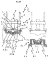
- the press A for the casting method according to one embodiment of the present invention is arranged along the molding line, opposite to a pouring device P of a tilting-type ladle.
- This press A comprises a movable frame 1 to be connected to a carriage (not shown) which runs back-and-forth in the crosswise directions (left-right directions in Fig.1) S; a up and down means B attached to the movable frame 1; a plate that presses a mold 3 connected to the end portion 2a of a rod 2 of the up and down means B; guide rods 4 provided at the four corners of the plate that presses the mold 3; for example, four fixing means C which support the upper mold F1 on two opposite sides of the four sides of the plate that presses the mold 3; a detection means D to detect the pressure which the upper mold F1 receives from the molten metal 12 poured into the lower mold after the pouring is completed, and the lower mold F2 (the pressure the upper mold F1 receives from the molten metal 12 and the parting plane of the upper mold and the lower mold) when the upper mold overlaps the lower mold; and a control means E.
- the guide rods 4, according to the embodiment of the present invention, are provided per
- the up and down means B uses an electric servo-cylinder that can control its position, and can also control the speed very accurately, but the embodiment is not limited to this means if the rod 2 can be lifted and lowered by, for example, electrical, hydraulic or pneumatic means.
- the electric servo-cylinder incorporates a screw structure, a drive-motor, a rotary encoder acting as a device to detect the position, and the like.
- an electric servo-cylinder that can control the speed and a linear scale that can detect and control the position can also be used.
- the fixing means C is not limited to a particular means, and it can be structured so as to consist of a driving mechanism such as an air cylinder, and a clamping part which rotates, extends, or contracts by means of the driving mechanism, so long as it can support the upper mold F1 on the plate that presses the mold 3.
- a support structure that uses an electromagnet or one that uses a suction support can be adopted.
- the detection means D is not limited to a specific means. It can suitably be selected depending on the kind of up and down means, so long as it has a function to detect the pressure that the upper mold F1 receives from the molten metal 12 and the lower mold F2.
- the control means E consists of an operation-circuit for the back and forth movement of a carriage, an operation-circuit for controlling the lifting and lowering of the up and down means B, such as the lifting speed, the lowering speed or stopping of it, an operation-circuit for a fixing means C and a control-circuit that interfaces, connects, and controls these operation-circuits, and a memory that stores information on the status of the upper mold, which information is input in advance.
- the lowering speed as a movement of the rod 2 of the up and down means is arranged so as to be at the predetermined first speed until the predetermined position (the distance from the surface of the molten metal 12 to the convex portion 13 of the upper mold F1) is reached just before the upper mold F1 starts contacting the surface of the molten metal 12, which is poured into a concave portion 11 of the lower mold F2, and also arranged so as to be at the predetermined second speed after the upper mold is further lowered beyond the predetermined position.
- control means E controls the movement of the up and down means B in such a way that it stops the lowering of the upper mold F1, based on a signal when the detection means D detects and obtains, as information on the status of the upper mold, the information that the pressure that the upper mold F1 receives from the molten metal 12 and from the lower mold F2 has reached a certain predetermined level.
- the predetermined position of the upper mold F1 relates to a shape of the convex portion 13 of the upper mold F1, which shape corresponds to a shape of a casting, and it relates to the predetermined first speed, which is the lowering speed of the up and down means B.
- the predetermined first speed which is the lowering speed of the up and down means B.
- the predetermined position must be moved farther away so as to prevent the air from remaining in the molten metal and from being involved in the casting, when the upper mold and the lower mold overlap. That is, the distance between the upper mold F1 and the surface of the molten metal 12 must be greater.
- the predetermined position and the first speed are suitably adjusted based on experiments which have used various shapes of castings, temperatures of the poured molten metals, and materials of the molten metals.
- the shape of the convex portion 13, as the shape of the casting is of a pyramid, and the temperature of the poured molten metal is higher than that of the liquid-phase line by more than 100 to 200 °C. Therefore, the first speed is set at the maximum speed listed in the catalogue for the electric servo cylinder, for example, at about 375 mm/sec, and the predetermined position is set at 1-100 mm.
- the upper mold must promptly overlap the lower mold and the shape of the mold must be pressure-transferred, before the molten metal poured into the lower mold solidifies. Therefore, if the predetermined second speed is high, the molten metal 12 is affected by an excessive pressure. It may cause a penetration of the surface of a casting. On the other hand, if the predetermined second speed is low, the molten metal 12 may solidify in the pressing process, so that the upper mold F1 cannot reach the predetermined completion position.
- the second speed is suitably adjusted based on experiments which have been made in various manufacturing conditions, varying, for example, the weight, the shape of castings, and the quantity and the temperature of the molten metal.
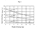
- the mark " ⁇ " in Fig. 2 shows the result of experiments where no penetrations for the molten metal at temperatures of about 1360 °C and about 1400 °C were found.
- the mark " ⁇ ” shows the result of experiments indicating that there were not any penetrations for the molten metal at about 1400 °C, but that there were a few penetrations for the molten metal at about 1360 °C.
- the mark “X” shows the result of experiments where a penetration was found regardless of the temperatures of the molten metals. The areas where the penetrations were found are shown by "R" in Fig. 3.
- Fig. 2 shows that the relationship between a weight of a casting and the second speed can be expressed by a quadratic curve that shows that the weight of the casting decreases as the second speed increases.
- a line UL showing the upper speed limit for the second speed
- a line DL showing its lower speed limit
- a control means E preferably comprises a memory circuit that stores a preset formula expressing the relationship of the weight of a casting and the second speed, and an input circuit that sets the second speed to a speed that suitably corresponds to the weight of the casting.
- a casting of good quality can be produced by setting the second speed to suitably correspond to the weight of the casting.
- the pressure can be predetermined by experiments, based on the surface area of the parting plane of the upper mold, the shapes of the upper and lower molds, and the speed of the press.
- the experiments are made by changing the temperature of the molten metal (the temperature of the molten metal being poured).
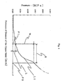
- the pressure increases gradually from the point P1, where the upper mold starts contacting the lower mold after the upper mold is lowered at the second speed. Then it starts increasing linearly from the point P2, to where the upper mold has been lowered by a predetermined distance.
- the pressure W was at 0.010 MPa.
- the surface area of the parting plane of the upper mold was 88,842 mm 2
- the second speed as a lowering movement of the up and down means B was 30 mm/sec.
- the curves of the pressures are similar even when the temperature of the poured molten metal is changed. That is, as in Figs. 4 and 5, the area of the pressure L has different shapes in the start-up period up to the point P1, where the upper mold starts contacting the lower mold. This is because the convex portion of the upper mold is affected by the viscosity of the molten metal when it enters the molten metal in the lower mold.
- the curves of the pressures L1 and L2 show almost the same pressing characteristics from the point P1 up to the boundary point P2 where the upper mold F1 does not excessively penetrate.
- the upper mold stops being lowered at a certain point. This is based on the information that the pressure has reached a predetermined level.
- This information comes from the information obtained, within the area "R”, on the pressures that the upper mold receives from the molten metal and from the lower mold, from the point P1, where the upper mold, which overlaps the lower molds, starts contacting the lower mold up to the boundary point P2 where the upper mold F1 does not excessively penetrate.
- the upper mold can be stopped from being lowered at a certain time and distance. This is based on information that the distance of the descent of the upper mold reaches a predetermined distance. This information comes from among the information, within the area "R", on the distance that the upper mold is lowered from the point P1, where the upper mold, which overlaps the lower molds, starts contacting the lower mold up to the boundary point P2, where the upper mold F1 does not excessively penetrate.
- a device for detecting this position such as a rotary encoder or a linear scale, is also used as a detecting means.
- the mold consists of a lower mold F2 and an upper mold F1.
- the lower mold F2 is a mold molded in a molding flask 22, by a green sand molding method, using green sand 31.
- the lower mold F2 has a concave portion 11 having the shape of a casting.
- the upper mold F1 is a mold molded in a molding flask 32, by the green sand molding method, using green sand 31.
- the upper mold F1 has a convex portion 13, having the shape of a casting, which convex portion forms a cavity that is required to produce a casting.
- the upper mold F1 in the inverted position is transferred by a conveyor line 51, by, for example, a roller conveyor, after the molding is completed, by lowering the mold pressing plate 3, the upper mold F1 is fixed to the mold pressing plate 3 of the press by the fixing means C. Then the upper mold is moved backward from the molding line and is kept at a stand-by position. The lower mold F2 is then transferred and is fixed on the stool 52 at a position where the molten metal is poured.
- the fixing is made, for example, by inserting rods of a positioning cylinder 53, through openings formed at the four corners of the lower mold F2 and the stool 52 where the lower mold F2 is loaded.
- a pouring machine P which is at a stand-by position off the molding line, is transferred close to the lower mold F2.
- the molten metal is then poured into a convex portion 11 of the lower mold in the amount of 120% or less of the volume of the cavity.
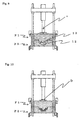
- the pouring machine is retracted from the molding line, and, as shown in Fig. 7, the press A is transferred to the position where the upper mold F1 is positioned above the lower mold F2.
- the upper mold is lowered, at the first speed of 375 mm/s (shown by an arrow V), to a position 15 mm farther away from the position where it starts contacting the molten metal 12, which is filled in the lower mold.
- the lowering speed of the upper mold F1 is changed to the second speed of 15 mm/s (shown by an arrow V).
- the upper mold is further lowered, keeping any distortion of the molten metal to a minimum, and the convex portion 13 of the upper mold F1 enters the molten metal 12.
- the upper mold F1 overlaps the lower mold, and it starts contacting the lower mold F2.
- the upper mold F1 stops being lowered at a position where it does not excessively penetrate, and when the pressure as measured by a load cell used as a detection means reaches 0.004 MPa. After duration of a certain time, the clamp is removed and the pressing work is completed.
- a sand mold is affected by the pressure of the molding, the characteristics of the sand, the shape of the pattern, and its measurements, especially its height (hereafter called molding conditions).
- molding conditions especially its height
- the sand mold often presents different measurements.
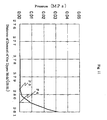
- a descending stroke is determined, as shown in Fig. 11, by measuring the pressure on the upper mold when it overlaps the lower mold, when the upper mold is considered to complete a pressing and when it is not any longer being lowered and under the conditions that the lower mold does not contain any molten metal.
- the upper mold and the lower mold start contacting each other, if the pressure at the overlapping plane (parting plane) formed by the upper mold and the lower mold is about 0.01 MPa, the upper mold and the lower mold are considered to be firmly attached at point P4. Then the descending stroke of the upper mold (the position of completion of pressing) is determined to be at about 280.4 mm.
- the molding method to produce a casting comprises a process of lowering the upper mold toward the lower mold; a process of detecting a relationship between the descending stroke of the upper mold and the pressure that the upper mold receives from the lower mold when the upper mold overlaps the lower mold; and a process of setting, based on that relationship, a descending stroke of the upper mold under that pressure.
- a mold with a molding flask is used.
- a mold in a back metal process which is intended, for example, to minimize a use of the foundry sand, and where the foundry sand is blown from a blow-in opening 23b onto the surface of a permanent mold 23a such as the upper mold F3 and the lower mold F4, as shown in Fig. 12, and which has formed a shape of a sand layer 23c, can also produce a casting that has as highly precise dimensions as those produced by a mold that uses a molding flask.
- the operational structure of the press A and its control are basically the same as those of the press used when the mold with a molding flask is used.
- the backup is not limited to a permanent mold.
- a back metal formed by metal balls, cement, mortar, or the like, can also be used.
- the sand layer that forms a portion of a shape of a casting can be suitably molded by various known molding methods, such as a green sand mold, shell mold, cold box molding process, self-hardening mold, and the like.
- this molding method can use a flaskless mold, where a sand mold is stripped from the molding flask after the molding or the matching of the molds is completed.
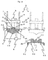
- Figs. 13-15 show schematic views of the press when a sand mold is stripped from the molding flask after the matching of the molds is completed.
- the press A2 comprises: guide-rods 42 that support the upper mold F5 and the lower mold F6 after molding is completed; a up and down means B2 to lift and lower the upper mold F5; a mold stripping means G to strip a sand mold 6 from a molding flask 25 after the upper mold F5 overlaps the lower mold F6; and a stool 52b on which the sand mold 6 is placed.
- the molten metal 12 is cast after it is poured in the lower mold F6, and the upper mold F5 and the lower mold F6 are overlapped by the hoist means B2 (Fig. 14). Then a stripping plate 8 which is placed at the end portion of a mold stripping means G, is lowered and the sand mold 6 is placed on the stool 52b (see Fig. 15).
- Fig. 16 shows a schematic view of the press when the sand mold is stripped from the molding flask after molding is completed.
- the pressing of the mold can be performed under the same conditions as in a case of a mold using the molding flask.
- the fixing means C2 that holds the upper sand mold F7 and the mold-pressing plate 3 is not limited to any specific structure so long as it can fix the upper mold F7 to the mold-pressing plate 3.
- the fixing means clamps the upper sand mold F7 and fix it to the pressing plate 3 by means of air cylinders, or the like, that are positioned at opposite sides of the upper sand mold F7.
- the flaskless mold is suitably molded by various known molding methods such as a green sand mold, shell mold, cold box molding process, self-hardening mold, and the like.
- Fig. 1 shows a schematic view of the press for casting in one embodiment of the present invention.
- Fig. 2 shows the relationship between the weight of a casting and the second speed.
- Fig. 3 shows a portion where a penetration has affected the casting.
- Fig. 4 shows a curve of the pressure.
- Fig. 5 shows a curve of the pressure when the temperature of the molten metal is varied.
- Fig. 6 shows a chart of the press for pouring the molten metal.
- Fig. 7 shows a view where the upper mold is transferred to the position where it is positioned above the lower mold after the pouring of the molten metal is completed.
- Fig. 8 shows a view where the upper mold is lowered at the first speed.
- Fig. 9 shows a view where the upper mold is lowered at the second speed.
- Fig. 10 shows a view where the upper mold stops lowering after it overlaps the lower mold and pressing is completed.
- Fig. 11 shows a curve of the pressure when there is no molten metal in the lower mold.
- Fig. 12 shows a schematic view in one embodiment of the press for casting by the back metal method.
- Fig. 13 shows a schematic view in one embodiment of the press for casting, illustrating the first process for stripping a sand mold from a molding flask after matching the molds.
- Fig. 14 shows a schematic view in one embodiment of the press for casting, illustrating the second process for stripping a sand mold from a molding flask after matching the molds.
- Fig. 10 shows a view where the upper mold stops lowering after it overlaps the lower mold and pressing is completed.
- Fig. 11 shows a curve of the pressure when there is no molten metal in the lower mold.
- Fig. 12 shows a schematic view in one embodiment of the press for casting by the back metal method.
- FIG. 15 shows a schematic view in one embodiment of the press for casting, illustrating the third process for stripping a sand mold from a molding flask after matching the molds.
- Fig. 16 shows a schematic view in one embodiment of the press for casting when a sand mold has been stripped from the molding flask after the molding was completed.
Landscapes
- Engineering & Computer Science (AREA)
- Mechanical Engineering (AREA)
- Casting Devices For Molds (AREA)
Applications Claiming Priority (3)
| Application Number | Priority Date | Filing Date | Title |
|---|---|---|---|
| JP2006286041 | 2006-10-20 | ||
| JP2006319712 | 2006-11-28 | ||
| JP2007070275 | 2007-03-19 |
Publications (2)
| Publication Number | Publication Date |
|---|---|
| EP1829631A2 true EP1829631A2 (de) | 2007-09-05 |
| EP1829631A3 EP1829631A3 (de) | 2007-10-31 |
Family
ID=38325946
Family Applications (1)
| Application Number | Title | Priority Date | Filing Date |
|---|---|---|---|
| EP07011874A Withdrawn EP1829631A3 (de) | 2006-10-20 | 2007-06-18 | Gussverfahren zur Herstellung eines Gussteils und beim Gussverfahren verwendete Presse |
Country Status (5)
| Country | Link |
|---|---|
| US (1) | US8327913B2 (de) |
| EP (1) | EP1829631A3 (de) |
| JP (1) | JP2010506726A (de) |
| CN (1) | CN101528388B (de) |
| WO (1) | WO2008047503A1 (de) |
Cited By (2)
| Publication number | Priority date | Publication date | Assignee | Title |
|---|---|---|---|---|
| US8061409B2 (en) * | 2006-10-16 | 2011-11-22 | Sintokogio, Ltd. | Mold |
| CN119897451A (zh) * | 2025-04-02 | 2025-04-29 | 朝阳飞马车辆设备股份公司 | 一种刹车盘铸造用铸芯生产模具 |
Families Citing this family (6)
| Publication number | Priority date | Publication date | Assignee | Title |
|---|---|---|---|---|
| EP2357050B1 (de) * | 2010-02-10 | 2012-10-31 | Loramendi, S.COOP. | Formmaschine für kastenlose Formen |
| CN102240795B (zh) * | 2011-07-20 | 2013-04-10 | 北京交通大学 | 一种汽车用制动底板毛坯的铸造方法及其使用的铸型 |
| JP5832028B2 (ja) * | 2012-08-27 | 2015-12-16 | 本田技研工業株式会社 | プレス鋳造装置およびプレス鋳造方法 |
| KR102185401B1 (ko) * | 2020-07-06 | 2020-12-01 | 주식회사 에치디엘 | 부품 제조 장치 및 부품 제조 시스템 |
| CN113600789A (zh) * | 2021-07-14 | 2021-11-05 | 江西省铭鑫荣智能科技有限公司 | 一种精密结构件加工用多轴式压铸机械及其实施方法 |
| CN113953485B (zh) * | 2021-09-17 | 2023-03-14 | 天津市天锻压力机有限公司 | 一种基于升压速率控制的液态模锻成形工艺方法 |
Family Cites Families (16)
| Publication number | Priority date | Publication date | Assignee | Title |
|---|---|---|---|---|
| US4049040A (en) * | 1975-08-07 | 1977-09-20 | N L Industries, Inc. | Squeeze casting apparatus and method |
| SU725805A1 (ru) * | 1977-05-10 | 1980-04-05 | Горьковский Политехнический Институт Им. А.А.Жданова | Штамп дл жидкой штамповки |
| JPS62230467A (ja) * | 1985-11-30 | 1987-10-09 | Akio Nakano | 鋳造用成形型 |
| SE469684B (sv) * | 1990-10-05 | 1993-08-23 | Tour & Andersson Ab | Saett och anordning vid pressgjutning |
| JP3086711B2 (ja) * | 1991-03-27 | 2000-09-11 | 松尾工業株式会社 | 鋳造方法 |
| JPH07112638B2 (ja) * | 1991-05-02 | 1995-12-06 | 株式会社ヨシツカ精機 | 粉末成形プレスの加圧制御方法 |
| US5269364A (en) * | 1992-03-06 | 1993-12-14 | Sintokogio Ltd. | Low pressure die casting apparatus |
| JPH0810890A (ja) * | 1994-06-24 | 1996-01-16 | Sintokogio Ltd | 半溶融アルミニウムビレットの加圧成形方法 |
| GB9501263D0 (en) * | 1995-01-23 | 1995-03-15 | Snowden Pte Ltd | A door assembly |
| US5595236A (en) * | 1995-05-08 | 1997-01-21 | Korea Institute Of Science And Technology | Vertical squeeze casting apparatus |
| US6957687B2 (en) * | 2001-08-06 | 2005-10-25 | Sintokogio, Ltd. | Method and system for monitoring a molding machine |
| JP2005034851A (ja) * | 2003-07-15 | 2005-02-10 | Ube Machinery Corporation Ltd | 半凝固金属成形体鍛造方法及びその鍛造装置 |
| JP2005052871A (ja) | 2003-08-06 | 2005-03-03 | Sintokogio Ltd | 鋳造方法およびその鋳型 |
| JP2005074461A (ja) * | 2003-08-29 | 2005-03-24 | Nisshin Seisakusho:Kk | 成形品の製造方法 |
| JP4447391B2 (ja) * | 2003-10-23 | 2010-04-07 | アイシン高丘株式会社 | ディスクロータの製造装置及び製造方法 |
| US9174268B2 (en) * | 2005-03-04 | 2015-11-03 | Agency For Science, Technology And Research | Method and apparatus for forging |
-
2007
- 2007-06-18 EP EP07011874A patent/EP1829631A3/de not_active Withdrawn
- 2007-06-29 CN CN2007800389713A patent/CN101528388B/zh active Active
- 2007-06-29 JP JP2009514993A patent/JP2010506726A/ja active Pending
- 2007-06-29 WO PCT/JP2007/063509 patent/WO2008047503A1/en not_active Ceased
- 2007-06-29 US US12/311,891 patent/US8327913B2/en active Active
Cited By (2)
| Publication number | Priority date | Publication date | Assignee | Title |
|---|---|---|---|---|
| US8061409B2 (en) * | 2006-10-16 | 2011-11-22 | Sintokogio, Ltd. | Mold |
| CN119897451A (zh) * | 2025-04-02 | 2025-04-29 | 朝阳飞马车辆设备股份公司 | 一种刹车盘铸造用铸芯生产模具 |
Also Published As
| Publication number | Publication date |
|---|---|
| CN101528388B (zh) | 2011-12-14 |
| US20100307707A1 (en) | 2010-12-09 |
| US8327913B2 (en) | 2012-12-11 |
| JP2010506726A (ja) | 2010-03-04 |
| EP1829631A3 (de) | 2007-10-31 |
| CN101528388A (zh) | 2009-09-09 |
| WO2008047503A1 (en) | 2008-04-24 |
Similar Documents
| Publication | Publication Date | Title |
|---|---|---|
| US8327913B2 (en) | Casting method to produce a casting and press used for the casting method | |
| EP1927415B1 (de) | Gießverfahren, Oberformanordnung und Verfahren zum Befestigen des Kerns an der Oberform | |
| US8061409B2 (en) | Mold | |
| CN107716872A (zh) | 一种大型工作台铸件的铸造方法 | |
| JPH06122062A (ja) | 連続差圧鋳造法 | |
| US5595236A (en) | Vertical squeeze casting apparatus | |
| CN120325896A (zh) | 一种铝合金熔模精密铸造用的反重力浇注工装及方法 | |
| CN201067793Y (zh) | 精铸离心铸造装置 | |
| JPS5911383B2 (ja) | タイヤ成形加硫用金型の低圧鋳造用鋳型 | |
| CN117098620B (zh) | 用于倾转浇注重力铸造的铸造装置 | |
| CA1171632A (en) | Process and apparatus for casting rounds, slabs, and the like | |
| KR100832248B1 (ko) | 알루미늄 휠 주조장치 | |
| CN219563539U (zh) | 一种机压成型无碳钢包砖的设备 | |
| JP4430739B2 (ja) | 鋳物製品の鋳造方法および該鋳造方法に用いられるプレス装置 | |
| JP4883403B2 (ja) | 鋳物製品の鋳造方法 | |
| CN220880493U (zh) | 一种金属复合板锭模具 | |
| CN222494787U (zh) | 一种石英方坩埚顶出脱模装置 | |
| CN219561369U (zh) | 高效型半固态金属浆料压铸成型设备 | |
| CN113953446B (zh) | 一种便于脱模的砂型铸造模具及其使用方法 | |
| JP2849312B2 (ja) | 高圧鋳造方法 | |
| CN210702465U (zh) | 一种铝型材压铸模具 | |
| WO2008091721A1 (en) | Continuous steel slab caster and methods using same | |
| JP2001225147A (ja) | 鋳型の造型注湯方法における粒状充填物充填装置 | |
| JPH05154644A (ja) | 直接加圧高圧鋳造装置 | |
| CN105964978A (zh) | 一种挤压铸造模具 |
Legal Events
| Date | Code | Title | Description |
|---|---|---|---|
| PUAI | Public reference made under article 153(3) epc to a published international application that has entered the european phase |
Free format text: ORIGINAL CODE: 0009012 |
|
| AK | Designated contracting states |
Kind code of ref document: A2 Designated state(s): AT BE BG CH CY CZ DE DK EE ES FI FR GB GR HU IE IS IT LI LT LU LV MC MT NL PL PT RO SE SI SK TR |
|
| AX | Request for extension of the european patent |
Extension state: AL BA HR MK YU |
|
| PUAL | Search report despatched |
Free format text: ORIGINAL CODE: 0009013 |
|
| AK | Designated contracting states |
Kind code of ref document: A3 Designated state(s): AT BE BG CH CY CZ DE DK EE ES FI FR GB GR HU IE IS IT LI LT LU LV MC MT NL PL PT RO SE SI SK TR |
|
| AX | Request for extension of the european patent |
Extension state: AL BA HR MK YU |
|
| RIC1 | Information provided on ipc code assigned before grant |
Ipc: B22D 18/00 20060101AFI20070927BHEP |
|
| 17P | Request for examination filed |
Effective date: 20080121 |
|
| AKX | Designation fees paid |
Designated state(s): AT BE BG CH CY CZ DE DK EE ES FI FR GB GR HU IE IS IT LI LT LU LV MC MT NL PL PT RO SE SI SK TR |
|
| 17Q | First examination report despatched |
Effective date: 20100119 |
|
| STAA | Information on the status of an ep patent application or granted ep patent |
Free format text: STATUS: THE APPLICATION HAS BEEN WITHDRAWN |
|
| 18W | Application withdrawn |
Effective date: 20100412 |