EP1828586B1 - Kolbenfenster mit scuppersolts und freiguss - Google Patents
Kolbenfenster mit scuppersolts und freiguss Download PDFInfo
- Publication number
- EP1828586B1 EP1828586B1 EP05814203A EP05814203A EP1828586B1 EP 1828586 B1 EP1828586 B1 EP 1828586B1 EP 05814203 A EP05814203 A EP 05814203A EP 05814203 A EP05814203 A EP 05814203A EP 1828586 B1 EP1828586 B1 EP 1828586B1
- Authority
- EP
- European Patent Office
- Prior art keywords
- piston
- outer diameter
- window surface
- region
- recess
- Prior art date
- Legal status (The legal status is an assumption and is not a legal conclusion. Google has not performed a legal analysis and makes no representation as to the accuracy of the status listed.)
- Expired - Lifetime
Links
Images
Classifications
-
- F—MECHANICAL ENGINEERING; LIGHTING; HEATING; WEAPONS; BLASTING
- F02—COMBUSTION ENGINES; HOT-GAS OR COMBUSTION-PRODUCT ENGINE PLANTS
- F02F—CYLINDERS, PISTONS OR CASINGS, FOR COMBUSTION ENGINES; ARRANGEMENTS OF SEALINGS IN COMBUSTION ENGINES
- F02F3/00—Pistons
-
- F—MECHANICAL ENGINEERING; LIGHTING; HEATING; WEAPONS; BLASTING
- F16—ENGINEERING ELEMENTS AND UNITS; GENERAL MEASURES FOR PRODUCING AND MAINTAINING EFFECTIVE FUNCTIONING OF MACHINES OR INSTALLATIONS; THERMAL INSULATION IN GENERAL
- F16J—PISTONS; CYLINDERS; SEALINGS
- F16J9/00—Piston-rings, e.g. non-metallic piston-rings, seats therefor; Ring sealings of similar construction
- F16J9/08—Piston-rings, e.g. non-metallic piston-rings, seats therefor; Ring sealings of similar construction with expansion obtained by pressure of the medium
Definitions
- the invention relates to a piston of an internal combustion engine having the features of the preamble of patent claim 1.
- Pistons of internal combustion engines which have a piston crown with a ring field and a piston shaft arranged below it, are known.
- Such pistons are for example also referred to as a box piston or piston with a box design.
- a pin bore is present, wherein around the pin bore around a relation to the outer diameter of the piston recessed window surface is formed.
- at least one depression is present in the region of the lowermost annular groove within the annular field of the piston, via which the oil collected from the lowermost ring is collected in the operation of the piston and passed over the window surface in the direction of the lower edge of the piston skirt.
- the invention provides a remedy in that the at least one recess outside the particularly stressed area above the pin bore and thus is arranged approximately at the edge of the window surface in the transition region to the shank surface of the piston skirt, wherein the particularly stressed area, starting from a vertex of the pin hole extends in the direction of the lower edge of the ring field.
- the effect of the recesses is retained, namely that the oil collected by the oil scraper ring in the last annular groove can be discharged over the window surface downwards.
- cracking is effectively prevented because the at least one recess in such area is disposed around the pin hole in the upper portion of the window surface, which is not particularly stressed.
- a thickening is provided, which is also set back behind the outer diameter of the piston.
- a thickening can also help to arrange the recess in an area adjacent to the vertex of the pin bore, which may nevertheless be particularly stressed.
- the areas set back relative to the outer diameter of the piston which may be the at least one depression, the thickening and the entire window area around the pin bore, may be at least partially, in particular completely in the clearance and / or or can be produced by machining. If the recessed surfaces are made in the clearance, the negative casting mold of the piston or of the piston blank has projecting regions which form the recessed surfaces after the casting of the piston blank. This has the advantage that once a mold with the corresponding protruding areas must be made, which then represent the recessed surfaces with each casting of a piston blank.
- a piston blank is cast with a constant and continuous outer diameter and then removed during machining the recessed surfaces by machining. This is particularly useful when numerically controlled machines (CNC machines) are used during fine machining of the piston.
- CNC machines numerically controlled machines
- the transitions from deeper surfaces, where the reference is the outer diameter of the piston are rounded to prevent break points that would allow a crack during piston operation.
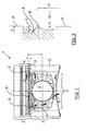
- FIG. 1 shows a one-piece piston 1 in the so-called box design, wherein the piston 1 has a piston head 2 (optionally with a combustion bowl not shown here) and a piston shaft 3 arranged below it. It should be noted that the invention for any piston types (as well as for pendulum piston) is applicable.
- the piston head 2 has in known manner a ring field 4 with three annular grooves on the rule, the piston shaft 3 has two diametrically opposed shank surfaces 5, with which the piston 1 is supported in the operation of the internal combustion engine on the cylinder surfaces and guided to this. Furthermore, the piston shaft 3 has a pin bore 6 for receiving a piston pin, with which the piston 1 is connected via a connecting rod, not shown here. In the area around the pin bore 6 around a window surface 7 is provided, which is set back behind the outer diameter of the piston 1, while on the outer diameter of the piston 1, the shaft surfaces 5 are.
- At least one recess 8 (four depressions as a rule) is (are) present in the region of a lowermost annular groove 9, this depression 8 also being referred to as a scapperslot.
- the reference numeral 10 indicates a region which is particularly stressed during operation of the piston 1, this particularly stressed region 10 also being present on the right of the vertex of the pin bore 6.
- the depressions 8 cause the oil collected by the oil scraper ring arranged in the lowermost annular groove 9 to be lowered over the window surface 7 present next to the bolt bore 6 (as viewed in FIG FIG. 1 ) is derived, so that an indicated with the arrows oil flow 11 is formed.
- the arrangement of the recesses 8 in addition to the particularly stressed area 10 thus has the advantage that in the region of the recesses 8 cracks can no longer form, since the material thickness is lower due to the recessed surfaces and cracking would threaten if the recesses 8 in particularly stressed area 10 would be arranged. Looking at the FIG. 1 can be seen that thus the recesses 8 are arranged approximately above that region in which the window surface 7 merges into the shaft surfaces 5.
- a thickening 12 is provided, wherein depending on the geometric design (in particular depth of the recess 8, dimensioning of the thickening 12 and depth of the window surface 7), the recess 8 in the edge region (the distant from the vertex of the pin bore area) can be arranged.
- FIG. 2 referring to a section AA in double scale according to FIG. 1 represents.
- both the position of the recess 8, the lowest annular groove 9 and the thickening 12 can be seen.
- These areas, as well as the window area 7, are recessed inwardly from an outer diameter D indicated at 13.
- the degree of reset depends on the geometric conditions and the distribution of forces, wherein the depth of the recess 8 is to be chosen so that the oil collected by the arranged in the lowest annular groove 9 oil scraper ring over the transition region into the window surface 7, in particular on the thickening 12, can be discharged in a sufficient amount during the movement of the piston 1.
- the recess 8 will have a round shape, which is realized, for example, by a bore, but may also be made in the groove:
- the width of the transition region from the recess 8 into the window surface 7 and thus the width of the thickening 12 is preferably greater as the radial extent of the recess 8 in order to ensure a sufficient flow of oil 11 in the direction of the window surface 7. But it is also conceivable that this transition region has the same or a smaller width than that of the recess 8.
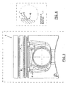
- FIG. 3 shows a further embodiment of the invention, in which case the recess 8 is not executed in a round shape (for example, realized as a bore), but has a rectangular shape with rounded edges.
- the wells 8 are again outside of the particularly stressed area 10, wherein in the transition region of the recess 8 in the window surface 7, the thickening 12 is present.
- Such forms of the recess 8, the thickening 12 and the window surface 7, as in FIG. 3 shown are, can be produced in a particularly advantageous manner in the share. However, this does not rule out that after the casting-technical production of these surfaces still a machining, especially a fine machining takes place.
- FIG. 4 is a section AA in scale 1 to 1 according to FIG. 3 represents.
- the recess 8 is not only in the area below the lowermost annular groove 9, but extends over this time.
- the invention is used in any piston 1 of an internal combustion engine, but preferably in pistons of a lightweight material, such as aluminum, and then in larger-volume internal combustion engines, especially those that are used to drive trucks.
Landscapes
- Engineering & Computer Science (AREA)
- General Engineering & Computer Science (AREA)
- Mechanical Engineering (AREA)
- Chemical & Material Sciences (AREA)
- Combustion & Propulsion (AREA)
- Pistons, Piston Rings, And Cylinders (AREA)
- Closing And Opening Devices For Wings, And Checks For Wings (AREA)
- Wing Frames And Configurations (AREA)
- Acyclic And Carbocyclic Compounds In Medicinal Compositions (AREA)
Description
- Die Erfindung betrifft einen Kolben einer Brennkraftmaschine mit den Merkmalen des Oberbegriffs des Patentanspruchs 1.
- Kolben von Brennkraftmaschinen, die einen Kolbenboden mit einem Ringfeld und einem unterhalb dessen angeordneten Kolbenschaft aufweisen, sind bekannt. Solche Kolben werden beispielsweise auch als Kastenkolben oder Kolben mit einem Kastendesign bezeichnet. Es ist bekannt, dass im Bereich des Kolbenschaftes eine Bolzenbohrung vorhanden ist, wobei um die Bolzenbohrung herum eine gegenüber dem äußeren Durchmesser des Kolbens zurückgesetzte Fensterfläche ausgebildet ist. Weiterhin ist es bekannt, dass im Bereich der untersten Ringnut innerhalb des Ringfeldes des Kolbens zumindest eine Vertiefung vorhanden ist, über die das von dem untersten Ring gesammelte Öl im Betreib des Kolbens gesammelt und über die Fensterfläche in Richtung der Unterkante des Kolbenschaftes geleitet wird. Im Betrieb der bekannten Kolben hat sich herausgestellt, dass die Vertiefungen derart oberhalb der Bolzenbohrung angeordnet sind, dass sie sich in einem besonders beanspruchten Bereich befindet. Dieser besonders beanspruchte Bereich des Kolbens befindet sich rechts und links neben dem Scheitelpunkt der Bolzenbohrung, da sich der Kolben, insbesondere der Kolbenboden, während seines Betriebes um den in der Bolzenbohrung angeordneten Bolzen verformt. Wenn nun die Vertiefungen in diesem besonders beanspruchten Bereich liegen, bilden sie eine Sollbruchstelle, so dass es im Betrieb des Kolbens, insbesondere beim Einsatz in heutigen hoch beanspruchten Dieselbrennkraftmaschinen, zu Rissen kommt. Solche Ausgestaltungen sind aus
JP 08 121243A EP-A-0 529 714 ,US-A-1 675 174 oderUS 2002/046593 A1 bekannt. - Demgegenüber schafft die Erfindung Abhilfe dadurch, dass die zumindest eine Vertiefung außerhalb des besonders beanspruchten Bereiches oberhalb der Bolzenbohrung und somit in etwa am Rand der Fensterfläche im Übergangsbereich zu der Schaftfläche des Kolbenschaftes angeordnet ist, wobei sich der besonders beanspruchte Bereich ausgehend von einem Scheitelpunkt der Bolzenbohrung in Richtung der Unterkante des Ringfeldes erstreckt.
- Damit bleibt einerseits die Wirkung der Vertiefungen erhalten, dass über sie nämlich das vom Ölabstreifring in der letzten Ringnut gesammelte Öl über die Fensterfläche nach unten abgeleitet werden kann. Andererseits wird eine Rissbildung wirksam verhindert, weil die zumindest eine Vertiefung in einem solchen Bereich im oberen Bereich der Fensterfläche um die Bolzenbohrung herum angeordnet ist, der nicht besonders beansprucht ist.
- Ergänzend dazu ist vorgesehen, dass in einem Übergangsbereich von der Vertiefung in Richtung der Fensterfläche eine Verdickung vorgesehen ist, die auch hinter dem äußeren Durchmesser des Kolbens zurückgesetzt ist. Dadurch wird die Entstehung der Rissbildung weiterhin wirksam verhindert, wobei eine solche Verdickung auch dazu beitragen kann, die Vertiefung in einem Bereich neben dem Scheitelpunkt der Bolzenbohrung anzuordnen, der dennoch besonders beansprucht sein kann.
- In Weiterbildung der Erfindung ist vorgesehen, dass die gegenüber dem äußern Durchmesser des Kolbens zurückgesetzten Flächen, bei denen es sich um die zumindest eine Vertiefung, die Verdickung sowie die gesamte Fensterfläche um die Bolzenbohrung herum handeln kann, zumindest teilweise, insbesondere vollständig im Freiguss und / oder durch spanabhebende Bearbeitung herstellbar sind. Werden die zurückgesetzten Flächen im Freiguss hergesellt, weist die Negativ-Gießform des Kolbens beziehungsweise des Kolbenrohlings vorstehende Bereiche auf, die nach dem Gießen des Kolbenrohlings die zurückgesetzten Flächen bilden. Dies hat den Vorteil, dass einmal eine Gießform mit den entsprechenden vorstehenden Bereichen gefertigt werden muss, die dann die zurückgesetzten Flächen bei jedem Guß eines Kolbenrohlings abbilden. Ergänzend oder alternativ dazu ist es denkbar, dass zum Beispiel ein Kolbenrohling mit einem gleichbleibenden und durchgehenden Außendurchmesser gegossen wird und anschließend bei der Feinbearbeitung die zurückgesetzten Flächen durch spanabhebende Bearbeitung abgetragen werden. Dies bietet sich insbesondere dann an, wenn bei der Feinbearbeitung des Kolbens numerisch gesteuerte Maschinen (CNC-Maschinen) zur Anwendung kommen. Bei der Herstellung der zurückgesetzten Flächen ist unbedingt zu beachten, dass die Übergänge von tiefer liegenden Flächen, wobei der Bezug der äußere Durchmesser des Kolbens ist, gerundet ausgeführt werden, um Sollbruchstellen, die einen Riss während des Betriebes des Kolben ermöglichen würden, zu verhindern.
- Ausführungsbeispiele der Erfindung, auf die diese jedoch nicht beschränkt sind, sind im folgenden beschrieben und an Hand der Figuren erläutert.
- Es zeigen:
-
Figur 2 : Schnitt A-A im Maßstab 2 zu 1 gemäßFigur 1 , -
Figur 3 : Ein weiteres Ausführungsbeispiel eines erfindungsgemäßen Kolbens, -
Figur 4 : Schnitt A-A im Maßstab 1 zu 1 gemäßFigur 3 . -
Figur 1 zeigt einen einteiligen Kolben 1 im sogenannten Kastendesign, wobei der Kolben 1 einen Kolbenboden 2 (gegebenenfalls mit einer hier nicht dargestellten Brennraummulde) und einen unterhalb dessen angeordneten Kolbenschaft 3 aufweist. An dieser sei darauf hingewiesen, daß die Erfindung für beliebige Kolbenbauarten (so auch für Pendelschaftkolben) anwendbar ist. - Der Kolbenboden 2 weist in an sich bekannter Weise ein Ringfeld 4 mit im Regelfall drei Ringnuten auf, wobei der Kolbenschaft 3 zwei diametral gegenüberliegende Schaftflächen 5 aufweist, mit denen der Kolben 1 im Betrieb der Brennkraftmaschine sich an den Zylinderlaufflächen abstützt und an diesen geführt ist. Weiterhin weist der Kolbenschaft 3 eine Bolzenbohrung 6 zur Aufnahme eines Kolbenbolzens auf, mit dem der Kolben 1 über ein hier nicht dargestelltes Pleuel verbunden ist. Im Bereich um die Bolzenbohrung 6 herum ist eine Fensterfläche 7 vorgesehen, die hinter dem äußeren Durchmesser des Kolbens 1 zurückgesetzt ist, während auf dem äußeren Durchmesser des Kolbens 1 die Schaftflächen 5 liegen. Zumindest eine Vertiefung 8 (im Regelfall vier Vertiefungen) ist (sind) im Bereich einer untersten Ringnut 9 vorhanden, wobei diese Vertiefung 8 auch als Scapperslot bezeichnet wird. Links von dem Scheitelpunkt der Bolzenbohrung 6 ist mit der Bezugsziffer 10 ein im Betrieb des Kolbens 1 besonders beanspruchter Bereich eingezeichnet, wobei dieser besonders beanspruchte Bereich 10 auch rechts vom Scheitelpunkt der Bolzenbohrung 6 vorhanden ist. Die Vertiefungen 8 bewirken, dass das von dem in der untersten Ringnut 9 angeordneten Ölabstreifring gesammelte Öl über die neben der Bolzenbohrung 6 vorhandene Fensterfläche 7 nach unten (bei Betrachtung der
Figur 1 ) abgeleitet wird, so dass ein mit den Pfeilen bezeichneter Ölfluss 11 entsteht. Die Anordnung der Vertiefungen 8 neben dem besonders beanspruchten Bereich 10 hat somit den Vorteil, dass sich im Bereich der Vertiefungen 8 keine Risse mehr bilden können, da hier die Materialstärke aufgrund der zurückgesetzten Flächen geringer ist und eine Rissbildung drohen würde, wenn die Vertiefungen 8 im besonders beanspruchten Bereich 10 angeordnet wären. Bei Betrachtung derFigur 1 ist erkennbar, dass somit die Vertiefungen 8 in etwa oberhalb desjenigen Bereiches angeordnet sind, bei dem die Fensterfläche 7 in die Schaftflächen 5 übergeht. Zur weiteren wirksamen Verhinderung von Rissbildungen ist noch beim Übergang von der Vertiefung 8 in die Fensterfläche 7 eine Verdickung 12 vorgesehen, wobei je nach geometrischer Gestaltung (insbesondere Tiefe der Vertiefung 8, Dimensionierung der Verdickung 12 und Tiefe der Fensterfläche 7) die Vertiefung 8 auch im Randbereich (der vom Scheitelpunkt der Bolzenbohrung entfernte Bereich) angeordnet werden kann. - Zur weiteren Verdeutlichung der Erfindung wird noch auf die
Figur 2 verwiesen, die einen Schnitt A-A im doppelten Maßstab gemäßFigur 1 darstellt. Hier sind sowohl die Lage der Vertiefung 8, der untersten Ringnut 9 und der Verdickung 12 erkennbar. Diese Bereiche, genauso wie die Fensterfläche 7, sind gegenüber einem äußeren Durchmesser D, der mit der Bezugsziffer 13 versehen ist, nach innen zurückgesetzt. Das Maß der Zurücksetzung richtet sich nach den geometrischen Verhältnisse und der Kräfteverteilung, wobei die Tiefe der Vertiefung 8 so zu wählen ist, dass das von dem in der untersten Ringnut 9 angeordneten Ölabstreifring gesammelte Öl über den Übergangsbereich in die Fensterfläche 7, insbesondere über die Verdickung 12, in ausreichender Menge während der Bewegung des Kolbens 1 abgeführt werden kann. Zur Vermeidung von Rissbildungen ist dabei die Verdickung 12 verstärkt ausgeführt, dass heißt, dass sie gegenüber dem äußeren Durchmesser D weniger zurückgesetzt ist als die Vertiefung 8 beziehungsweise die Fensterfläche 7. Besonders wichtig bei der Ausgestaltung gemäßFigur 2 ist es, dass, wie gezeigt, die Übergangsbereich von der untersten Ringnut 9 beziehungsweise der Vertiefung 8 über die Verdickung 12 in Richtung der Fensterfläche 7 gerundet ausgeführt sind, genau so wie übrigens auch der Übergangsbereich der Fensterfläche 7 in die Schaftfläche 5. Die Verdickung 12 bildet somit eine Materialansammlung zur Verstärkung und Verhinderung von Rissbildungen in diesem Bereich, gewährleistet gleichzeitig aber auch den Ölfluss 11, da sie hinter dem äußeren Durchmesser D zurückgesetzt ist. Im Regelfall wird die Vertiefung 8 eine runde Form aufweisen, die zum Beispiel durch eine Bohrung realisiert ist, aber auch im Freiguss hergestellt sein kann: Die Breite des Übergangsbereiches von der Vertiefung 8 in die Fensterfläche 7 und somit die Breite der Verdickung 12 ist vorzugsweise größer als die radiale Erstreckung der Vertiefung 8, um einen ausreichenden Ölfluss 11 in Richtung der Fensterfläche 7 zu gewährleisten. Denkbar ist es aber auch, dass dieser Übergangsbereich die gleiche oder eine kleinere Breite als die der Vertiefung 8 aufweist. -
Figur 3 zeigt ein weiteres Ausführungsbeispiel der Erfindung, wobei hier die Vertiefung 8 nicht in runder Form (zum Beispiel als Bohrung realisiert) ausgeführt ist, sondern eine Rechteckform mit abgerundeten Kannten aufweist. Auch hier befinden sich die Vertiefungen 8 wieder außerhalb des besonders beanspruchten Bereiches 10, wobei im Übergangsbereich von der Vertiefung 8 in die Fensterfläche 7 die Verdickung 12 vorhanden ist. Solche Formen der Vertiefung 8, der Verdickung 12 sowie der Fensterfläche 7, wie sie inFigur 3 dargestellt sind, lassen sich in besonders vorteilhafter Weise im Freiguss herstellen. Das schließt allerdings nicht aus, dass nach der gießtechnischen Herstellung dieser Flächen noch eine spanabhebende Bearbeitung, insbesondere eine Feinbearbeitung, erfolgt. - Ergänzend zu
Figur 3 wird noch aufFigur 4 verwiesen, die eine Schnitt A-A im Maßstab 1 zu 1 gemäßFigur 3 darstellt. Hier ist noch sehr gut zu erkennen, dass sich die Vertiefung 8 nicht nur im Bereich unterhalb der untersten Ringnut 9 befindet, sondern sich über diese hinweg erstreckt. - Die Erfindung kommt zur Anwendung bei jedem möglichen Kolben 1 einer Brennkraftmaschine, allerdings vorzugsweise bei Kolben aus einem Leichtbauwerkstoff, wie Aluminium, und dann bei größervolumigen Brennkraftmaschinen, insbesondere solche, die dem Antrieb von Lastkraftwagen dienen.
-
- 1.
- Kolben
- 2.
- Kolbenboden
- 3.
- Kolbenschaft
- 4.
- Ringfeld
- 5.
- Schaftfläche
- 6.
- Bolzenbohrung
- 7.
- Fensterfläche
- 8.
- Vertiefung
- 9.
- unterste Ringnut
- 10.
- besonders beanspruchter Bereich
- 11.
- Ölfluß
- 12.
- Verdickung
- 13.
- äußerer Durchmesser D
Claims (3)
- Kolben (1) einer Brennkraftmaschine, aufweisend einen Kolbenboden (2) mit einem Ringfeld (4) und einem unterhalb dessen angeordneten Kolbenschaft (3), der Schaftflächen (5) und eine um eine Bolzenbohrung (6) herum angeordnete und gegenüber einem äußere Durchmesser (13) des Kolbens (1) zurückgesetzte Fensterfläche (7) aufweist, wobei zumindest eine Vertiefung (8) im Bereich einer untersten Ringnut (9) für einen Ölfluß (11) in Richtung der Fensterfläche (7) während der Bewegung des Kolbens (1) vorgesehen ist, und in einem Übergangsbereich von der Vertiefung (8) in Richtung der Fensterfläche (7) eine Verdickung (12) vorgesehen ist, die auch hinter dem äußeren Durchmesser (13) des Kolbens (1) zurückgesetzt ist dadurch gekennzeichnet, dass die zumindest eine Vertiefung (8) außerhalb eines besonders beanspruchten Bereiches (10) oberhalb der Bolzenbohrung (6) angeordnet ist, wobei die zumindest eine Vertiefung (8) in demjenlgen Bereich angeordnet ist, bei dem die Fensterfläche (7) in die Schaftfläche (5) übergeht.
- Kolben (1) nach Anspruch 1, dadurch gekennzeichnet, dass die gegenüber dem äußeren Durchmesser (13) des Kolbens (1) zurückgesetzten Flächen zumindest teilweise, insbesondere vollständig, im Freiguß herstellbar sind.
- Kolben (1) nach Anspruch 1 oder 2, dadurch gekennzeichnet, dass die gegenüber dem äußeren Durchmesser (13) des Kolbens (1) zurückgesetzten Flächen zumindest teilweise, insbesondere vollständig durch spanabhebende Bearbeitung herstellbar ist.
Applications Claiming Priority (2)
| Application Number | Priority Date | Filing Date | Title |
|---|---|---|---|
| DE102004061777A DE102004061777A1 (de) | 2004-12-22 | 2004-12-22 | Kolbenfenster mit Scupperslots und Freiguss |
| PCT/EP2005/012708 WO2006072293A1 (de) | 2004-12-22 | 2005-11-29 | Kolbenfenster mit scuppersolts und freiguss |
Publications (2)
| Publication Number | Publication Date |
|---|---|
| EP1828586A1 EP1828586A1 (de) | 2007-09-05 |
| EP1828586B1 true EP1828586B1 (de) | 2011-01-12 |
Family
ID=35841683
Family Applications (1)
| Application Number | Title | Priority Date | Filing Date |
|---|---|---|---|
| EP05814203A Expired - Lifetime EP1828586B1 (de) | 2004-12-22 | 2005-11-29 | Kolbenfenster mit scuppersolts und freiguss |
Country Status (9)
| Country | Link |
|---|---|
| US (1) | US7730828B2 (de) |
| EP (1) | EP1828586B1 (de) |
| JP (1) | JP2008524502A (de) |
| KR (1) | KR100923811B1 (de) |
| CN (1) | CN101111670B (de) |
| AT (1) | ATE495357T1 (de) |
| BR (1) | BRPI0519257A2 (de) |
| DE (2) | DE102004061777A1 (de) |
| WO (1) | WO2006072293A1 (de) |
Families Citing this family (8)
| Publication number | Priority date | Publication date | Assignee | Title |
|---|---|---|---|---|
| DE102007045465A1 (de) * | 2007-09-24 | 2009-04-02 | Federal-Mogul Nürnberg GmbH | Kolben mit Ölversorgungsrinne für Nabenbohrungen |
| DE102007051711A1 (de) * | 2007-10-30 | 2009-05-07 | Ks Kolbenschmidt Gmbh | Funktionsoptimierte Gestaltung von Kolben-Ringfeldbereichen |
| DE102011012685A1 (de) * | 2011-03-01 | 2012-09-06 | Mahle International Gmbh | Kolben für einen Verbrennungsmotor |
| DE102011119525A1 (de) | 2011-11-26 | 2013-05-29 | Mahle International Gmbh | Kolben für einen Verbrennungsmotor |
| DE102015006354A1 (de) * | 2015-05-19 | 2016-11-24 | Mahle International Gmbh | Kolben für einen Verbrennungsmotor |
| DE102018211361B4 (de) * | 2018-07-10 | 2020-03-05 | Federal-Mogul Nürnberg GmbH | Kolben für einen Verbrennungsmotor |
| GB2590701B (en) | 2019-12-27 | 2022-06-22 | Caterpillar Motoren Gmbh & Co | Piston for an internal combustion engine |
| US12258922B2 (en) * | 2022-11-30 | 2025-03-25 | Cummins Inc. | Piston for assembly with a cylinder |
Family Cites Families (8)
| Publication number | Priority date | Publication date | Assignee | Title |
|---|---|---|---|---|
| US1675174A (en) * | 1925-08-28 | 1928-06-26 | Stephen D Hartog | Piston |
| US3805677A (en) * | 1972-03-01 | 1974-04-23 | Trw Inc | Two-piece oil-cooled piston with thermal expansion control |
| US4428330A (en) * | 1982-09-08 | 1984-01-31 | Kabushiki Kaisha Komatsu Seisakusho | Piston for internal combustion engines |
| US5172626A (en) * | 1991-08-22 | 1992-12-22 | General Motors Corporation | Stabilized piston skirt having varying peaks and concave surfaces |
| JPH08121243A (ja) * | 1994-10-26 | 1996-05-14 | Nippon Soken Inc | 内燃機関用のピストン |
| JPH09112342A (ja) * | 1995-10-19 | 1997-04-28 | Toyota Motor Corp | 内燃機関のピストン |
| AU2002213255A1 (en) * | 2000-10-18 | 2002-04-29 | Federal Mogul Corporation | Multi-axially forged piston |
| US6973723B2 (en) * | 2003-01-08 | 2005-12-13 | International Engine Intellectual Property Company, Llc | Piston formed by powder metallurgical methods |
-
2004
- 2004-12-22 DE DE102004061777A patent/DE102004061777A1/de not_active Ceased
-
2005
- 2005-11-29 BR BRPI0519257-9A patent/BRPI0519257A2/pt not_active IP Right Cessation
- 2005-11-29 US US11/722,608 patent/US7730828B2/en active Active
- 2005-11-29 DE DE502005010863T patent/DE502005010863D1/de not_active Expired - Lifetime
- 2005-11-29 KR KR1020077016531A patent/KR100923811B1/ko not_active Expired - Fee Related
- 2005-11-29 WO PCT/EP2005/012708 patent/WO2006072293A1/de not_active Ceased
- 2005-11-29 EP EP05814203A patent/EP1828586B1/de not_active Expired - Lifetime
- 2005-11-29 CN CN2005800474933A patent/CN101111670B/zh not_active Expired - Fee Related
- 2005-11-29 AT AT05814203T patent/ATE495357T1/de active
- 2005-11-29 JP JP2007547224A patent/JP2008524502A/ja active Pending
Also Published As
| Publication number | Publication date |
|---|---|
| ATE495357T1 (de) | 2011-01-15 |
| KR100923811B1 (ko) | 2009-10-27 |
| US7730828B2 (en) | 2010-06-08 |
| CN101111670B (zh) | 2011-03-16 |
| DE102004061777A1 (de) | 2006-08-17 |
| JP2008524502A (ja) | 2008-07-10 |
| DE502005010863D1 (de) | 2011-02-24 |
| CN101111670A (zh) | 2008-01-23 |
| KR20070099616A (ko) | 2007-10-09 |
| EP1828586A1 (de) | 2007-09-05 |
| WO2006072293A1 (de) | 2006-07-13 |
| BRPI0519257A2 (pt) | 2009-01-06 |
| US20080202330A1 (en) | 2008-08-28 |
Similar Documents
| Publication | Publication Date | Title |
|---|---|---|
| DE4322832A1 (de) | Aus Stahl geschmiedetes Pleuel | |
| EP2342441B1 (de) | Kühlkanalkolben einer brennkraftmaschine mit einem verschlusselement, das den kühlkanal verschliesst | |
| EP2595771B1 (de) | Verfahren zur herstellung eines kühlkanalkolbens für brennkraftmaschinen und derart hergestellter kolben | |
| DE3604661A1 (de) | Kolben mit kolbenring | |
| DE2136594A1 (de) | Kolben mit einem die Mundung des Verbrennungsraumes umgebenden Einsatz stuck aus Metallegierung auf Kupferbasis | |
| EP3334918B1 (de) | Kolben für eine brennkraftmaschine | |
| DE2811840A1 (de) | Kolben | |
| WO2007025686A1 (de) | Leichtbaukolben | |
| DE10322921A1 (de) | Verfahren zur Herstellung eines einteiligen Kolbens für einen Verbrennungsmotor | |
| WO2013131937A1 (de) | Gegossener leichtmetallkolben, insbesondere ein aluminiumkolben | |
| EP1828586A1 (de) | Kolbenfenster mit scuppersolts und freiguss | |
| DE102013205908A1 (de) | Minuten-Kolbenring mit einer Rille | |
| EP1573236B1 (de) | Kolben für einen verbrennungsmotor | |
| DE102015201633A1 (de) | Kolben für einen Verbrennungsmotor sowie Verfahren zur Herstellung des Kolbens für einen Verbrennungsmotor | |
| DE102005041001A1 (de) | Leichtbaukolben | |
| WO2017016934A1 (de) | Kolben für einen verbrennungsmotor | |
| DE102018211361A1 (de) | Kolben für einen Verbrennungsmotor | |
| EP3452712B1 (de) | Kolben | |
| EP3988778B1 (de) | Kolben für eine brennkraftmaschine und herstellungsverfahren | |
| DE9405810U1 (de) | Aus Stahl geschmiedetes Pleuel | |
| EP3710686B1 (de) | Stahlkolben mit optimiertem design | |
| EP1704319B1 (de) | Zylinderkurbelgehäuse mit zylinderlaufbuchse | |
| DE102017108271A1 (de) | Kolben | |
| DE102005041002A1 (de) | Leichtbaukolben | |
| DE102004012142A1 (de) | Hebel für die Ventilsteuerung einer Kolbenmaschine |
Legal Events
| Date | Code | Title | Description |
|---|---|---|---|
| PUAI | Public reference made under article 153(3) epc to a published international application that has entered the european phase |
Free format text: ORIGINAL CODE: 0009012 |
|
| 17P | Request for examination filed |
Effective date: 20070614 |
|
| AK | Designated contracting states |
Kind code of ref document: A1 Designated state(s): AT BE BG CH CY CZ DE DK EE ES FI FR GB GR HU IE IS IT LI LT LU LV MC NL PL PT RO SE SI SK TR |
|
| DAX | Request for extension of the european patent (deleted) | ||
| 17Q | First examination report despatched |
Effective date: 20080409 |
|
| GRAP | Despatch of communication of intention to grant a patent |
Free format text: ORIGINAL CODE: EPIDOSNIGR1 |
|
| GRAC | Information related to communication of intention to grant a patent modified |
Free format text: ORIGINAL CODE: EPIDOSCIGR1 |
|
| GRAS | Grant fee paid |
Free format text: ORIGINAL CODE: EPIDOSNIGR3 |
|
| GRAA | (expected) grant |
Free format text: ORIGINAL CODE: 0009210 |
|
| AK | Designated contracting states |
Kind code of ref document: B1 Designated state(s): AT BE BG CH CY CZ DE DK EE ES FI FR GB GR HU IE IS IT LI LT LU LV MC NL PL PT RO SE SI SK TR |
|
| REG | Reference to a national code |
Ref country code: GB Ref legal event code: FG4D Free format text: NOT ENGLISH |
|
| REG | Reference to a national code |
Ref country code: CH Ref legal event code: EP |
|
| REG | Reference to a national code |
Ref country code: IE Ref legal event code: FG4D Free format text: LANGUAGE OF EP DOCUMENT: GERMAN |
|
| REF | Corresponds to: |
Ref document number: 502005010863 Country of ref document: DE Date of ref document: 20110224 Kind code of ref document: P |
|
| REG | Reference to a national code |
Ref country code: DE Ref legal event code: R096 Ref document number: 502005010863 Country of ref document: DE Effective date: 20110224 |
|
| REG | Reference to a national code |
Ref country code: NL Ref legal event code: VDEP Effective date: 20110112 |
|
| LTIE | Lt: invalidation of european patent or patent extension |
Effective date: 20110112 |
|
| PG25 | Lapsed in a contracting state [announced via postgrant information from national office to epo] |
Ref country code: PT Free format text: LAPSE BECAUSE OF FAILURE TO SUBMIT A TRANSLATION OF THE DESCRIPTION OR TO PAY THE FEE WITHIN THE PRESCRIBED TIME-LIMIT Effective date: 20110512 Ref country code: GR Free format text: LAPSE BECAUSE OF FAILURE TO SUBMIT A TRANSLATION OF THE DESCRIPTION OR TO PAY THE FEE WITHIN THE PRESCRIBED TIME-LIMIT Effective date: 20110413 Ref country code: SE Free format text: LAPSE BECAUSE OF FAILURE TO SUBMIT A TRANSLATION OF THE DESCRIPTION OR TO PAY THE FEE WITHIN THE PRESCRIBED TIME-LIMIT Effective date: 20110112 Ref country code: LV Free format text: LAPSE BECAUSE OF FAILURE TO SUBMIT A TRANSLATION OF THE DESCRIPTION OR TO PAY THE FEE WITHIN THE PRESCRIBED TIME-LIMIT Effective date: 20110112 Ref country code: LT Free format text: LAPSE BECAUSE OF FAILURE TO SUBMIT A TRANSLATION OF THE DESCRIPTION OR TO PAY THE FEE WITHIN THE PRESCRIBED TIME-LIMIT Effective date: 20110112 Ref country code: IS Free format text: LAPSE BECAUSE OF FAILURE TO SUBMIT A TRANSLATION OF THE DESCRIPTION OR TO PAY THE FEE WITHIN THE PRESCRIBED TIME-LIMIT Effective date: 20110512 Ref country code: ES Free format text: LAPSE BECAUSE OF FAILURE TO SUBMIT A TRANSLATION OF THE DESCRIPTION OR TO PAY THE FEE WITHIN THE PRESCRIBED TIME-LIMIT Effective date: 20110423 |
|
| REG | Reference to a national code |
Ref country code: IE Ref legal event code: FD4D |
|
| PG25 | Lapsed in a contracting state [announced via postgrant information from national office to epo] |
Ref country code: PL Free format text: LAPSE BECAUSE OF FAILURE TO SUBMIT A TRANSLATION OF THE DESCRIPTION OR TO PAY THE FEE WITHIN THE PRESCRIBED TIME-LIMIT Effective date: 20110112 Ref country code: CY Free format text: LAPSE BECAUSE OF FAILURE TO SUBMIT A TRANSLATION OF THE DESCRIPTION OR TO PAY THE FEE WITHIN THE PRESCRIBED TIME-LIMIT Effective date: 20110112 Ref country code: FI Free format text: LAPSE BECAUSE OF FAILURE TO SUBMIT A TRANSLATION OF THE DESCRIPTION OR TO PAY THE FEE WITHIN THE PRESCRIBED TIME-LIMIT Effective date: 20110112 Ref country code: BG Free format text: LAPSE BECAUSE OF FAILURE TO SUBMIT A TRANSLATION OF THE DESCRIPTION OR TO PAY THE FEE WITHIN THE PRESCRIBED TIME-LIMIT Effective date: 20110412 Ref country code: SI Free format text: LAPSE BECAUSE OF FAILURE TO SUBMIT A TRANSLATION OF THE DESCRIPTION OR TO PAY THE FEE WITHIN THE PRESCRIBED TIME-LIMIT Effective date: 20110112 Ref country code: NL Free format text: LAPSE BECAUSE OF FAILURE TO SUBMIT A TRANSLATION OF THE DESCRIPTION OR TO PAY THE FEE WITHIN THE PRESCRIBED TIME-LIMIT Effective date: 20110112 |
|
| PLBI | Opposition filed |
Free format text: ORIGINAL CODE: 0009260 |
|
| PLBI | Opposition filed |
Free format text: ORIGINAL CODE: 0009260 |
|
| PG25 | Lapsed in a contracting state [announced via postgrant information from national office to epo] |
Ref country code: DK Free format text: LAPSE BECAUSE OF FAILURE TO SUBMIT A TRANSLATION OF THE DESCRIPTION OR TO PAY THE FEE WITHIN THE PRESCRIBED TIME-LIMIT Effective date: 20110112 Ref country code: IE Free format text: LAPSE BECAUSE OF FAILURE TO SUBMIT A TRANSLATION OF THE DESCRIPTION OR TO PAY THE FEE WITHIN THE PRESCRIBED TIME-LIMIT Effective date: 20110112 Ref country code: EE Free format text: LAPSE BECAUSE OF FAILURE TO SUBMIT A TRANSLATION OF THE DESCRIPTION OR TO PAY THE FEE WITHIN THE PRESCRIBED TIME-LIMIT Effective date: 20110112 |
|
| PLAX | Notice of opposition and request to file observation + time limit sent |
Free format text: ORIGINAL CODE: EPIDOSNOBS2 |
|
| 26 | Opposition filed |
Opponent name: FEDERAL-MOGUL NUERNBERG GMBH Effective date: 20111010 |
|
| 26 | Opposition filed |
Opponent name: MAHLE INTERNATIONAL GMBH Effective date: 20111011 Opponent name: FEDERAL-MOGUL NUERNBERG GMBH Effective date: 20111010 |
|
| PG25 | Lapsed in a contracting state [announced via postgrant information from national office to epo] |
Ref country code: SK Free format text: LAPSE BECAUSE OF FAILURE TO SUBMIT A TRANSLATION OF THE DESCRIPTION OR TO PAY THE FEE WITHIN THE PRESCRIBED TIME-LIMIT Effective date: 20110112 Ref country code: RO Free format text: LAPSE BECAUSE OF FAILURE TO SUBMIT A TRANSLATION OF THE DESCRIPTION OR TO PAY THE FEE WITHIN THE PRESCRIBED TIME-LIMIT Effective date: 20110112 Ref country code: CZ Free format text: LAPSE BECAUSE OF FAILURE TO SUBMIT A TRANSLATION OF THE DESCRIPTION OR TO PAY THE FEE WITHIN THE PRESCRIBED TIME-LIMIT Effective date: 20110112 |
|
| PG25 | Lapsed in a contracting state [announced via postgrant information from national office to epo] |
Ref country code: IT Free format text: LAPSE BECAUSE OF FAILURE TO SUBMIT A TRANSLATION OF THE DESCRIPTION OR TO PAY THE FEE WITHIN THE PRESCRIBED TIME-LIMIT Effective date: 20110112 |
|
| REG | Reference to a national code |
Ref country code: DE Ref legal event code: R026 Ref document number: 502005010863 Country of ref document: DE Effective date: 20111010 |
|
| BERE | Be: lapsed |
Owner name: KS KOLBENSCHMIDT G.M.B.H. Effective date: 20111130 |
|
| PG25 | Lapsed in a contracting state [announced via postgrant information from national office to epo] |
Ref country code: MC Free format text: LAPSE BECAUSE OF NON-PAYMENT OF DUE FEES Effective date: 20111130 |
|
| REG | Reference to a national code |
Ref country code: CH Ref legal event code: PL |
|
| PG25 | Lapsed in a contracting state [announced via postgrant information from national office to epo] |
Ref country code: LI Free format text: LAPSE BECAUSE OF NON-PAYMENT OF DUE FEES Effective date: 20111130 Ref country code: CH Free format text: LAPSE BECAUSE OF NON-PAYMENT OF DUE FEES Effective date: 20111130 |
|
| PLBB | Reply of patent proprietor to notice(s) of opposition received |
Free format text: ORIGINAL CODE: EPIDOSNOBS3 |
|
| PG25 | Lapsed in a contracting state [announced via postgrant information from national office to epo] |
Ref country code: BE Free format text: LAPSE BECAUSE OF NON-PAYMENT OF DUE FEES Effective date: 20111130 |
|
| REG | Reference to a national code |
Ref country code: AT Ref legal event code: MM01 Ref document number: 495357 Country of ref document: AT Kind code of ref document: T Effective date: 20111129 |
|
| PG25 | Lapsed in a contracting state [announced via postgrant information from national office to epo] |
Ref country code: AT Free format text: LAPSE BECAUSE OF NON-PAYMENT OF DUE FEES Effective date: 20111129 |
|
| PGFP | Annual fee paid to national office [announced via postgrant information from national office to epo] |
Ref country code: FR Payment date: 20121130 Year of fee payment: 8 |
|
| PGFP | Annual fee paid to national office [announced via postgrant information from national office to epo] |
Ref country code: GB Payment date: 20121120 Year of fee payment: 8 |
|
| PG25 | Lapsed in a contracting state [announced via postgrant information from national office to epo] |
Ref country code: LU Free format text: LAPSE BECAUSE OF NON-PAYMENT OF DUE FEES Effective date: 20111129 |
|
| PG25 | Lapsed in a contracting state [announced via postgrant information from national office to epo] |
Ref country code: TR Free format text: LAPSE BECAUSE OF FAILURE TO SUBMIT A TRANSLATION OF THE DESCRIPTION OR TO PAY THE FEE WITHIN THE PRESCRIBED TIME-LIMIT Effective date: 20110112 |
|
| PG25 | Lapsed in a contracting state [announced via postgrant information from national office to epo] |
Ref country code: HU Free format text: LAPSE BECAUSE OF FAILURE TO SUBMIT A TRANSLATION OF THE DESCRIPTION OR TO PAY THE FEE WITHIN THE PRESCRIBED TIME-LIMIT Effective date: 20110112 |
|
| PLCK | Communication despatched that opposition was rejected |
Free format text: ORIGINAL CODE: EPIDOSNREJ1 |
|
| APBM | Appeal reference recorded |
Free format text: ORIGINAL CODE: EPIDOSNREFNO |
|
| APBP | Date of receipt of notice of appeal recorded |
Free format text: ORIGINAL CODE: EPIDOSNNOA2O |
|
| APAH | Appeal reference modified |
Free format text: ORIGINAL CODE: EPIDOSCREFNO |
|
| APBM | Appeal reference recorded |
Free format text: ORIGINAL CODE: EPIDOSNREFNO |
|
| APBP | Date of receipt of notice of appeal recorded |
Free format text: ORIGINAL CODE: EPIDOSNNOA2O |
|
| APAW | Appeal reference deleted |
Free format text: ORIGINAL CODE: EPIDOSDREFNO |
|
| APAY | Date of receipt of notice of appeal deleted |
Free format text: ORIGINAL CODE: EPIDOSDNOA2O |
|
| APBM | Appeal reference recorded |
Free format text: ORIGINAL CODE: EPIDOSNREFNO |
|
| APBP | Date of receipt of notice of appeal recorded |
Free format text: ORIGINAL CODE: EPIDOSNNOA2O |
|
| APBQ | Date of receipt of statement of grounds of appeal recorded |
Free format text: ORIGINAL CODE: EPIDOSNNOA3O |
|
| APBQ | Date of receipt of statement of grounds of appeal recorded |
Free format text: ORIGINAL CODE: EPIDOSNNOA3O |
|
| GBPC | Gb: european patent ceased through non-payment of renewal fee |
Effective date: 20131129 |
|
| REG | Reference to a national code |
Ref country code: FR Ref legal event code: ST Effective date: 20140731 |
|
| PG25 | Lapsed in a contracting state [announced via postgrant information from national office to epo] |
Ref country code: GB Free format text: LAPSE BECAUSE OF NON-PAYMENT OF DUE FEES Effective date: 20131129 Ref country code: FR Free format text: LAPSE BECAUSE OF NON-PAYMENT OF DUE FEES Effective date: 20131202 |
|
| PLAB | Opposition data, opponent's data or that of the opponent's representative modified |
Free format text: ORIGINAL CODE: 0009299OPPO |
|
| R26 | Opposition filed (corrected) |
Opponent name: MAHLE INTERNATIONAL GMBH Effective date: 20111011 |
|
| REG | Reference to a national code |
Ref country code: DE Ref legal event code: R100 Ref document number: 502005010863 Country of ref document: DE |
|
| APBU | Appeal procedure closed |
Free format text: ORIGINAL CODE: EPIDOSNNOA9O |
|
| PLBN | Opposition rejected |
Free format text: ORIGINAL CODE: 0009273 |
|
| STAA | Information on the status of an ep patent application or granted ep patent |
Free format text: STATUS: OPPOSITION REJECTED |
|
| 27O | Opposition rejected |
Effective date: 20180627 |
|
| PGFP | Annual fee paid to national office [announced via postgrant information from national office to epo] |
Ref country code: DE Payment date: 20241121 Year of fee payment: 20 |
|
| REG | Reference to a national code |
Ref country code: DE Ref legal event code: R071 Ref document number: 502005010863 Country of ref document: DE |