EP0529714A1 - Piston for internal combustion engine - Google Patents
Piston for internal combustion engine Download PDFInfo
- Publication number
- EP0529714A1 EP0529714A1 EP92202470A EP92202470A EP0529714A1 EP 0529714 A1 EP0529714 A1 EP 0529714A1 EP 92202470 A EP92202470 A EP 92202470A EP 92202470 A EP92202470 A EP 92202470A EP 0529714 A1 EP0529714 A1 EP 0529714A1
- Authority
- EP
- European Patent Office
- Prior art keywords
- skirt
- piston
- thrust
- plane
- axis
- Prior art date
- Legal status (The legal status is an assumption and is not a legal conclusion. Google has not performed a legal analysis and makes no representation as to the accuracy of the status listed.)
- Withdrawn
Links
Images


Classifications
-
- F—MECHANICAL ENGINEERING; LIGHTING; HEATING; WEAPONS; BLASTING
- F16—ENGINEERING ELEMENTS AND UNITS; GENERAL MEASURES FOR PRODUCING AND MAINTAINING EFFECTIVE FUNCTIONING OF MACHINES OR INSTALLATIONS; THERMAL INSULATION IN GENERAL
- F16J—PISTONS; CYLINDERS; SEALINGS
- F16J1/00—Pistons; Trunk pistons; Plungers
- F16J1/02—Bearing surfaces
-
- F—MECHANICAL ENGINEERING; LIGHTING; HEATING; WEAPONS; BLASTING
- F02—COMBUSTION ENGINES; HOT-GAS OR COMBUSTION-PRODUCT ENGINE PLANTS
- F02F—CYLINDERS, PISTONS OR CASINGS, FOR COMBUSTION ENGINES; ARRANGEMENTS OF SEALINGS IN COMBUSTION ENGINES
- F02F3/00—Pistons
- F02F3/02—Pistons having means for accommodating or controlling heat expansion
- F02F3/022—Pistons having means for accommodating or controlling heat expansion the pistons having an oval circumference or non-cylindrical shaped skirts, e.g. oval
Definitions
- This invention relates to a piston for an internal combustion engine and particularly to the shapes of the skirt of such a piston.
- the skirt may also include a variable longitudinal profile generally having a smaller variable diameter towards the top of the skirt near the piston ring belt and a larger diameter near the bottom, and having the bottom and top edge diameters slightly reduced.
- the present invention seeks to provide an improved piston for an internal combustion engine.
- the present invention can provide an improved piston skirt profile which can provide improved stability and reduced lateral and rotational (tilting) piston motion, especially at low temperatures, for reduced noise as well as improved distribution of thrust loads on the piston skirt so as to reduce wear and extend durability.
- An improved transverse cross-sectional shape for an engine piston skirt has been found.
- the improved shape properly applied, can better distribute thrust forces over the running surfaces and thereby reduce maximum skirt contact pressures and wear.
- lateral motion, tilting and piston slap may be reduced during warm-up and skirt lubrication can be improved.
- the skirt profile is formed by smoothly varying radii and includes the provision of slight concavities, or relative recesses, in the lateral cross-section profiles along the thrust plane of the piston.
- This can result in high points of piston radii at specified angles on either side of the thrust plane which stabilize the motion of the piston skirt in operation, including during warm-up.
- the high points can provide load carrying regions on either side of the thrust plane which support the piston and limit wear by reducing elastic deformation.
- the skirt is designed for each engine application to accommodate thermal growth and combustion force deformations of the piston and its associated cylinder as well as the flexibility (or stiffness) of the skirt and cylinder walls under the maximum thrust forces applied in operation so that the skirt load is widely distributed at maximum loads.
- the recess acts to retain lubricating oil for better lubrication of the skirt to reduce wear as well as aid noise reduction.
- the skirt lateral profiles are formed using a preferred mathematical relationship or formula which can be readily utilized by computer numerically controlled machines to form the desired configuration having a smooth, continuous skirt shape.
- the longitudinal profiles are preferably modified to provide deeper recesses at the top, or ring belt, end of the skirt with gradually reduced recess depths at the lateral cross-sections moving towards the bottom of the skirt.
- a piston 10 for an internal combustion engine includes the usual crown or head 11 that defines a top, combustion exposed, surface when installed in an engine cylinder (not shown).
- a ring belt 12 having a top ring groove 14, a second ring groove 15 and a third ring groove 16 adapted to receive conventional top and second compression rings and an oil ring (not shown).
- a skirt 18 through which extends a bore 19 for a piston pin.
- the exterior of the skirt has flat portions 20 that extend on either side of the pin bore 19 over the skirt length.
- the interior of the skirt 18 and the lower portion of the ring belt 12 are hollow except for bosses 21 surrounding the bore 19 which extend upwardly along the interior of the skirt 18 to the head 11 to carry gas forces directly from the head to the piston pin (not shown).
- the piston has a longitudinal or main axis 22 on which the exterior machining of the skirt and ring belt is centered, a piston pin axis 23 on which the bore 19 is centered and a thrust axis 24 normal to the pin axis 23.
- a transverse axis 25, parallel to the pin axis 23 intersects the main axis 22 and thrust axis 24 at a common point. If desired, the pin axis 23 may be coincident with rather than offset from the transverse axis 25.
- the main axis and the thrust axis define a thrust plane 26 along which the side thrust forces on the piston in operation are nominally applied.
- the skirt may be made as a continuously curved cylinder without flat portions 20 or the skirt may be interrupted by open areas instead of flat portions adjacent the pin bosses.
- the general features of the described embodiment may be applied to such alternative piston embodiments as well as to others not described.
- skirt and ring belt are commonly formed with a so-called barrel shape in which the largest diameter in the longitudinal profile is located along the thrust axis 24 normal to the piston pin bore and the diameters become progressively smaller above and below the pin bore.
- skirt as viewed in transverse section normal to the main axis 22, with a generally elliptical shape having the minor axis aligned with the pin axis and the major axis aligned with the thrust axis in the thrust plane.
- piston in this embodiment involves modification of the round or elliptical cross-section to provide relative recesses or apparent concavities along and adjacent the thrust plane so that the major thrust loads are distributed primarily over peak areas on either side of the thrust plane.
- This broadened load distribution tends to stabilize the piston motion in the cylinder and also provides a recess for retention of lubricant along the thrust plane on the thrust and counter-thrust surfaces of the piston.
- Figure 3 illustrates the general configuration of preferred piston skirt cross-sectional shapes for a family of pistons.
- the shapes are compared to a nominal circular diameter 27 from which the configurations 28 of two larger pistons indicated by dashed lines 28a and 28b are defined.
- the shapes illustrated are for the top of the piston skirt and the deviations from the circular diameter are enlarged about 500 times for clarity, as the actual deviations are too small to be apparent to the eye.
- a third skirt shape for a smaller diameter piston is illustrated by line 28c.
- the skirt configurations have apparent concavities with nominal diameters 32a-c in the thrust plane 26 on both the thrust and counter-thrust sides of the piston.
- the skirt radii smoothly increase to geometric peaks 34a-c. These peaks form the high points of the piston diameter in the cold as-formed condition and tend to concentrate the skirt loads at these points spaced from the thrust axis when the pistons reciprocate inside engine cylinders.
- the skirt radius Progressing angularly from the peaks to the longitudinal projection of the transverse axis 25, the skirt radius generally diminishes, though preferably in a curve which first falls beyond the envelope of the corresponding nominal diameter 32 and then returns to a diameter equal to or slightly less than that diameter at the projected transverse axis 25.
- skirt shapes may be different on the thrust and counter-thrust sides of the piston, it is normally acceptable and convenient to make them identical and they are so shown in the drawings. It should be understood that in a piston as shown in Figures 1 and 2, the portions of the skirt near the thrust axis are cut off at the flat portions 20 and so, in these zones, do not have the configurations shown in Figure 3. However, non-interrupted piston skirts could be made with these configurations if desired.
- the design of an embodiment of piston skirt is accomplished first by determining by known methods, such as physical testing or finite element computer simulations, the characteristics of the engine piston-cylinder combination. These include comparative thermal growth or dimensional change during operation from cold start to maximum load and temperature. Also the range of applied forces on the piston and cylinder and the stiffnesses of the structures are determined.
- skirt shapes are then determined at a series of vertically spaced points which best fit the piston skirt to the cylinder under the maximum loaded operating conditions at high temperatures with consideration to critical warm-up conditions. Depending upon the particular cylinder and piston structures involved, this generally results in a skirt configuration which is of greatest maximum diameter in the thrust plane 26 at the thrust axis 24 which passes through the piston pin axis 23. On either side, longitudinally, of the thrust plane, the skirt radius is generally reduced. Further, the longitudinal profile of the skirt is generally of reduced diameter above and below the piston pin axis 25.
- coefficients c1, c2 which determine the amount of camdrop that defines the skirt transverse profile at the various longitudinal locations is a matter of design choice based upon the structural and operational evaluations provided above to provide low friction operation while minimizing lateral piston motion.
Landscapes
- Engineering & Computer Science (AREA)
- General Engineering & Computer Science (AREA)
- Chemical & Material Sciences (AREA)
- Combustion & Propulsion (AREA)
- Mechanical Engineering (AREA)
- Pistons, Piston Rings, And Cylinders (AREA)
Abstract
A piston (10) with a skirt (18) shaped to accommodate distortion by changing thermal and load conditions is further modified to increase stability and broaden load distribution to reduce contact forces and wear by providing maximum radii lines (34) on either side of a longitudinal thrust plane (26) with reduced radius regions forming apparent concavities (35) therebetween.
Description
- This invention relates to a piston for an internal combustion engine and particularly to the shapes of the skirt of such a piston.
- It is known in the art relating to engine pistons to develop a skirt shape through various methods involving theoretical design and physical engine testing to define an acceptable shape for each engine application. It is intended to accommodate thermal growth, combustion force deformations and stiffness of the piston and its associated cylinder in operation while minimizing lateral and tilting motions of the piston that cause noise and wear. In one prior proposal, an abradable coating is provided on a piston skirt which is then run in an engine to be eroded so as to generate the desired shape of the skirt for use in a production version of the piston.
- Whatever the method of development used, it is now common in automotive vehicle engine pistons to provide a skirt having a generally oval configuration in lateral cross-section with a major axis between the thrust and counter-thrust sides. The skirt may also include a variable longitudinal profile generally having a smaller variable diameter towards the top of the skirt near the piston ring belt and a larger diameter near the bottom, and having the bottom and top edge diameters slightly reduced.
- The present invention seeks to provide an improved piston for an internal combustion engine.
- According to an aspect of the present invention, there is provided a piston as specified in claim 1.
- The present invention can provide an improved piston skirt profile which can provide improved stability and reduced lateral and rotational (tilting) piston motion, especially at low temperatures, for reduced noise as well as improved distribution of thrust loads on the piston skirt so as to reduce wear and extend durability.
- An improved transverse cross-sectional shape for an engine piston skirt has been found. The improved shape, properly applied, can better distribute thrust forces over the running surfaces and thereby reduce maximum skirt contact pressures and wear. In addition, lateral motion, tilting and piston slap may be reduced during warm-up and skirt lubrication can be improved.
- Preferably, the skirt profile is formed by smoothly varying radii and includes the provision of slight concavities, or relative recesses, in the lateral cross-section profiles along the thrust plane of the piston. This can result in high points of piston radii at specified angles on either side of the thrust plane which stabilize the motion of the piston skirt in operation, including during warm-up. The high points can provide load carrying regions on either side of the thrust plane which support the piston and limit wear by reducing elastic deformation.
- Advantageously, the skirt is designed for each engine application to accommodate thermal growth and combustion force deformations of the piston and its associated cylinder as well as the flexibility (or stiffness) of the skirt and cylinder walls under the maximum thrust forces applied in operation so that the skirt load is widely distributed at maximum loads. At lighter loads, the recess acts to retain lubricating oil for better lubrication of the skirt to reduce wear as well as aid noise reduction.
- In a preferred embodiment, the skirt lateral profiles are formed using a preferred mathematical relationship or formula which can be readily utilized by computer numerically controlled machines to form the desired configuration having a smooth, continuous skirt shape. The longitudinal profiles are preferably modified to provide deeper recesses at the top, or ring belt, end of the skirt with gradually reduced recess depths at the lateral cross-sections moving towards the bottom of the skirt.
- An embodiment of the present invention is described below, by way of illustration only, with reference to the accompanying drawings, in which:
- Figure 1 is a semi-schematic side view from the wrist pin axis of a piston with a skirt shaped according to an embodiment of the invention;
- Figure 2 is a cross-sectional view taken normal to the piston axis at the plane of the line 2-2 of Figure 1;
- Figure 3 is a diagrammatic view showing the exterior shapes of the tops of the skirts, with eccentricity magnified, for a family of pistons having skirts formed according to embodiments of the invention;
- Figure 4 is a side view of a piston having the full skirt length modified; and
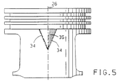
- Figure 5 is a view similar to Figure 4 showing a partial length modification of a piston skirt.
- Referring now to Figures 1 and 2 a
piston 10 for an internal combustion engine includes the usual crown orhead 11 that defines a top, combustion exposed, surface when installed in an engine cylinder (not shown). Below thehead 11 is aring belt 12 having atop ring groove 14, asecond ring groove 15 and a third ring groove 16 adapted to receive conventional top and second compression rings and an oil ring (not shown). Below thering belt 12 is askirt 18 through which extends abore 19 for a piston pin. - The exterior of the skirt has
flat portions 20 that extend on either side of the pin bore 19 over the skirt length. The interior of theskirt 18 and the lower portion of thering belt 12 are hollow except forbosses 21 surrounding thebore 19 which extend upwardly along the interior of theskirt 18 to thehead 11 to carry gas forces directly from the head to the piston pin (not shown). - The piston has a longitudinal or
main axis 22 on which the exterior machining of the skirt and ring belt is centered, apiston pin axis 23 on which thebore 19 is centered and athrust axis 24 normal to thepin axis 23. Atransverse axis 25, parallel to thepin axis 23 intersects themain axis 22 andthrust axis 24 at a common point. If desired, thepin axis 23 may be coincident with rather than offset from thetransverse axis 25. The main axis and the thrust axis define athrust plane 26 along which the side thrust forces on the piston in operation are nominally applied. - The foregoing describes portions of the piston construction which are conventional, it being understood that various alternative conventional configurations might also be utilized in the embodiment described below. For example, the skirt may be made as a continuously curved cylinder without
flat portions 20 or the skirt may be interrupted by open areas instead of flat portions adjacent the pin bosses. The general features of the described embodiment may be applied to such alternative piston embodiments as well as to others not described. - A normal goal in piston design is to select the skirt dimensions so that the piston will slide freely in the cylinder under all conditions of operation but that lateral and rotational motion, sometimes called piston slap, will be minimized to reduce impact loading and audible noise. Accordingly, in pistons of the type described, the skirt and ring belt are commonly formed with a so-called barrel shape in which the largest diameter in the longitudinal profile is located along the
thrust axis 24 normal to the piston pin bore and the diameters become progressively smaller above and below the pin bore. Also, it is common to form the skirt, as viewed in transverse section normal to themain axis 22, with a generally elliptical shape having the minor axis aligned with the pin axis and the major axis aligned with the thrust axis in the thrust plane. These departures from a right circular cylindrical configuration are intended to accommodate both the thermal growth of the piston and cylinder during operation and the deflections of the skirt and cylinder wall under the various load and speed conditions encountered. - The configuration of piston in this embodiment involves modification of the round or elliptical cross-section to provide relative recesses or apparent concavities along and adjacent the thrust plane so that the major thrust loads are distributed primarily over peak areas on either side of the thrust plane. This broadened load distribution tends to stabilize the piston motion in the cylinder and also provides a recess for retention of lubricant along the thrust plane on the thrust and counter-thrust surfaces of the piston.
- Figure 3 illustrates the general configuration of preferred piston skirt cross-sectional shapes for a family of pistons. The shapes are compared to a nominal
circular diameter 27 from which the configurations 28 of two larger pistons indicated bydashed lines line 28c. - The skirt configurations have apparent concavities with
nominal diameters 32a-c in thethrust plane 26 on both the thrust and counter-thrust sides of the piston. At predetermined angles Aa-c on either side of thethrust plane 26, the skirt radii smoothly increase togeometric peaks 34a-c. These peaks form the high points of the piston diameter in the cold as-formed condition and tend to concentrate the skirt loads at these points spaced from the thrust axis when the pistons reciprocate inside engine cylinders. Progressing angularly from the peaks to the longitudinal projection of thetransverse axis 25, the skirt radius generally diminishes, though preferably in a curve which first falls beyond the envelope of the corresponding nominal diameter 32 and then returns to a diameter equal to or slightly less than that diameter at the projectedtransverse axis 25. Although the skirt shapes may be different on the thrust and counter-thrust sides of the piston, it is normally acceptable and convenient to make them identical and they are so shown in the drawings. It should be understood that in a piston as shown in Figures 1 and 2, the portions of the skirt near the thrust axis are cut off at theflat portions 20 and so, in these zones, do not have the configurations shown in Figure 3. However, non-interrupted piston skirts could be made with these configurations if desired. - The design of an embodiment of piston skirt is accomplished first by determining by known methods, such as physical testing or finite element computer simulations, the characteristics of the engine piston-cylinder combination. These include comparative thermal growth or dimensional change during operation from cold start to maximum load and temperature. Also the range of applied forces on the piston and cylinder and the stiffnesses of the structures are determined.
- The skirt shapes are then determined at a series of vertically spaced points which best fit the piston skirt to the cylinder under the maximum loaded operating conditions at high temperatures with consideration to critical warm-up conditions. Depending upon the particular cylinder and piston structures involved, this generally results in a skirt configuration which is of greatest maximum diameter in the
thrust plane 26 at thethrust axis 24 which passes through thepiston pin axis 23. On either side, longitudinally, of the thrust plane, the skirt radius is generally reduced. Further, the longitudinal profile of the skirt is generally of reduced diameter above and below thepiston pin axis 25. - To modify the ideal skirt shape determined from this data, apparent concavities are provided near the thrust plane, as previously described, by slightly reducing the skirt diameter or radius at and adjacent to the
thrust plane 26. The amount of radius or diameter reduction preferably varies with the amount of thermal growth determined at the various longitudinal locations of the skirt and so is generally greater at the top of the skirt closest to thehead 11 andring belt 12 and lessens as the distance from the top of theskirt 18 is increased. The resulting maximum skirt radii at the various lateral sections along the skirt length form the ridges orgeometric peaks 34, separated by relatively concave regions orconcavities 35 which are shown in Figures 4 and 5 to extend along the full (Figure 4) or partial (Figure 5) length of the skirt on and beside thethrust plane 26. - To provide for ease of manufacture by computer numerical control (CNC) machining, it is preferable to obtain the resulting skirt shape by an approximating formula which generates a sinusoidal-like curve relative to the
base circle 27 from which it is measured. This formula may be shown as follows:

Where: - SD(t, z)
- = piston skirt diameter or radius as a function of location;
- t
- = angle measured from piston thrust axis which specifies circumferential skirt location;
- z
- = distance from piston top;
- ND
- = piston sizing diameter or radius along the thrust plane;
- P(z)
- = the diametral or radial difference between ND and SD along the skirt thrust line. This is a function varying with z, obtained by using multiple control points that are connected using conventional interpolation techniques. This quantity is referred to as skirt longitudinal profile;
- C(t,z,c1,c2)
- = c1(z)[sin²(t)-c2(z)sin²(2t)], amount of skirt diametrical or radial difference along the piston circumference, with respect to the thrust axis diameter or radius. This quantity is referred to as variable camdrop and/or transverse cross-section profile; and
- c1(z),c2(z)
- = variable camdrop coefficient functions varying with z, obtained by using multiple control points that are connected by interpolation.
- The selection of coefficients c1, c2 which determine the amount of camdrop that defines the skirt transverse profile at the various longitudinal locations is a matter of design choice based upon the structural and operational evaluations provided above to provide low friction operation while minimizing lateral piston motion.
Claims (4)
- A piston having a longitudinal axis (22) extending substantially perpendicularly to a combustion surface of the piston, and a skirt (18) extending across a thrust plane (26), the longitudinal axis of the piston lying in the thrust plane, the skirt including a substantially smooth outer surface and thrust and counter-thrust faces disposed substantially opposite to one another along the thrust plane (26), at least one of the thrust and counter-thrust faces having in ambient temperature and in an unloaded condition of the piston (10), in planes substantially perpendicular to the axis of the piston over an axial length extending from the top towards the bottom of the skirt, varying radii forming geometric peaks (34) of maximum skirt radii located at angles of up to 45 degrees on either side of the thrust plane (26), and portions (35) towards the thrust plane (26) forming an apparent concavity (35) at or proximate the thrust plane.
- A piston according to claim 1, wherein over the axial length of the skirt, the skirt is configured on the basis of the formula:

the terms of which are as herein defined. - A piston according to claim 1 or 2, wherein the or each apparent concavity extends along substantially the full axial length of the skirt.
- A piston according to claim 1 or 2, wherein the or each apparent concavity extends along a portion of the axial length of the skirt.
Applications Claiming Priority (2)
| Application Number | Priority Date | Filing Date | Title |
|---|---|---|---|
| US07/748,732 US5172626A (en) | 1991-08-22 | 1991-08-22 | Stabilized piston skirt having varying peaks and concave surfaces |
| US748732 | 1991-08-22 |
Publications (1)
| Publication Number | Publication Date |
|---|---|
| EP0529714A1 true EP0529714A1 (en) | 1993-03-03 |
Family
ID=25010684
Family Applications (1)
| Application Number | Title | Priority Date | Filing Date |
|---|---|---|---|
| EP92202470A Withdrawn EP0529714A1 (en) | 1991-08-22 | 1992-08-11 | Piston for internal combustion engine |
Country Status (3)
| Country | Link |
|---|---|
| US (1) | US5172626A (en) |
| EP (1) | EP0529714A1 (en) |
| JP (1) | JPH05223170A (en) |
Cited By (3)
| Publication number | Priority date | Publication date | Assignee | Title |
|---|---|---|---|---|
| WO2006072293A1 (en) * | 2004-12-22 | 2006-07-13 | Ks Kolbenschmidt Gmbh | Rotor recess with scupper slots and free casting |
| WO2006094532A1 (en) | 2005-03-11 | 2006-09-14 | Honeywell International, Inc. | Shape detail of a piston to avoid jamming within a distorted bore |
| CN102184293A (en) * | 2011-05-11 | 2011-09-14 | 重庆长安汽车股份有限公司 | Method for designing spatial curved surface of piston skirt |
Families Citing this family (17)
| Publication number | Priority date | Publication date | Assignee | Title |
|---|---|---|---|---|
| JP3541511B2 (en) * | 1995-07-07 | 2004-07-14 | いすゞ自動車株式会社 | piston |
| DE19643778C2 (en) * | 1996-10-23 | 2000-04-13 | Alcan Gmbh | Lightweight pistons |
| AT413233B (en) * | 2000-07-03 | 2005-12-15 | Verdichter Oe Ges M B H | PISTON RELEASE |
| DE10101605B4 (en) * | 2001-01-16 | 2005-11-17 | Federal-Mogul Nürnberg GmbH | Piston for internal combustion engines |
| US6502539B2 (en) | 2001-06-01 | 2003-01-07 | Federal-Mogul World Wide, Inc. | Articulated piston having a profiled skirt |
| US6862976B2 (en) | 2001-10-23 | 2005-03-08 | Federal-Mogul World Wide, Inc. | Monobloc piston |
| US7293497B2 (en) | 2005-11-03 | 2007-11-13 | Dresser, Inc. | Piston |
| US7302884B2 (en) * | 2005-11-03 | 2007-12-04 | Dresser, Inc. | Piston |
| DE102008018850A1 (en) * | 2007-11-30 | 2009-06-04 | Andreas Borst | Piston and process for its production |
| US8356550B2 (en) * | 2008-07-25 | 2013-01-22 | Federal-Mogul Corporation | Piston skirt with friction reducing oil recess and oil reservoir |
| US8437914B2 (en) | 2010-05-18 | 2013-05-07 | Ford Global Technologies | Electric motor enhanced driveability in vehicle handling and stability control events |
| JP5543908B2 (en) * | 2010-12-24 | 2014-07-09 | 本田金属技術株式会社 | Piston for engine |
| USD713422S1 (en) * | 2011-05-20 | 2014-09-16 | Federal-Mogul Corporation | Piston |
| WO2015120016A1 (en) | 2014-02-04 | 2015-08-13 | Federal-Mogul Corporation | Piston with abradable coating to generate appropriate contact geometry on running surface |
| KR101557434B1 (en) | 2014-06-13 | 2015-10-06 | 한국델파이주식회사 | Piston for master cylinder |
| DE102014010156A1 (en) * | 2014-07-09 | 2015-07-09 | Daimler Ag | Arrangement of a piston in a cylinder of a reciprocating internal combustion engine and piston for a reciprocating internal combustion engine |
| DE102017202463A1 (en) * | 2017-02-15 | 2018-08-16 | Mahle International Gmbh | Piston of an internal combustion engine |
Citations (3)
| Publication number | Priority date | Publication date | Assignee | Title |
|---|---|---|---|---|
| CH225228A (en) * | 1939-04-20 | 1943-01-15 | Schmidt Gmbh Karl | Pistons for internal combustion engines. |
| DE800351C (en) * | 1949-07-15 | 1950-10-30 | Mahle Kg | Light metal pistons for internal combustion engines |
| DE3022858A1 (en) * | 1980-06-19 | 1981-12-24 | Mahle Gmbh, 7000 Stuttgart | Piston for IC engine - has zones of least clearance to either side of oscillation axis to form oil cushion against cylinder |
Family Cites Families (19)
| Publication number | Priority date | Publication date | Assignee | Title |
|---|---|---|---|---|
| US1575751A (en) * | 1923-11-09 | 1926-03-09 | Fox Lee | Piston for internal-combustion engines |
| US2186375A (en) * | 1935-10-21 | 1940-01-09 | Sterling Corp | Piston |
| US2190207A (en) * | 1937-03-10 | 1940-02-13 | Cleveland Trust Co | Piston |
| US2352592A (en) * | 1941-02-18 | 1944-07-04 | Alexander M Alexandrescu | Expansion controlling piston construction |
| US2513814A (en) * | 1947-01-21 | 1950-07-04 | Aluminum Co Of America | Piston |
| DE1294740B (en) * | 1963-08-03 | 1969-05-08 | Schmidt Gmbh Karl | Pistons with a non-circular cross-section for internal combustion engines |
| US4009332A (en) * | 1976-06-28 | 1977-02-22 | International Business Machines Corporation | Memory management system for an ink jet copier |
| JPS57163982A (en) * | 1981-04-01 | 1982-10-08 | Sanyo Electric Co | High frequency heater |
| JPS59190455A (en) * | 1983-04-11 | 1984-10-29 | Mazda Motor Corp | Method of settling shape of piston for internal- combustion engine |
| DE3418454A1 (en) * | 1984-05-18 | 1985-12-19 | Kolbenschmidt AG, 7107 Neckarsulm | LIGHT METAL PISTON |
| DE3437111A1 (en) * | 1984-10-10 | 1986-04-10 | Kolbenschmidt AG, 7107 Neckarsulm | LIGHT METAL PISTON |
| GB8431725D0 (en) * | 1984-12-15 | 1985-01-30 | Ae Plc | Pistons for i c engines/compressors |
| IT1208802B (en) * | 1985-04-12 | 1989-07-10 | Ae Borgo Spa | PISTON IMPROVEMENT FOR ALTERNATIVE ENDOTHERMAL ENGINES TO REALIZE THE OIL CUSHION LUBRICATION OF THE SAME |
| IT1182507B (en) * | 1985-07-12 | 1987-10-05 | Ae Borgo Spa | PISTONS WITH ASYMMETRIC PROFILE FOR INTERNAL COMBUSTION ENGINES |
| DE3527032A1 (en) * | 1985-07-27 | 1987-01-29 | Mahle Gmbh | SUBMERSIBLE PISTON, IN PARTICULAR FOR COMBUSTION ENGINES |
| DE3531801A1 (en) * | 1985-09-06 | 1987-03-19 | Kolbenschmidt Ag | LIGHT METAL PISTON |
| JPS6285152A (en) * | 1985-09-27 | 1987-04-18 | Honda Motor Co Ltd | piston |
| US4864986A (en) * | 1988-09-26 | 1989-09-12 | Brunswick Corporation | Two-cycle engine with offset piston ovality |
| US5107807A (en) * | 1989-09-28 | 1992-04-28 | Nissan Motor Company, Ltd. | Piston for internal combustion engine |
-
1991
- 1991-08-22 US US07/748,732 patent/US5172626A/en not_active Expired - Fee Related
-
1992
- 1992-08-11 EP EP92202470A patent/EP0529714A1/en not_active Withdrawn
- 1992-08-21 JP JP4222856A patent/JPH05223170A/en active Pending
Patent Citations (3)
| Publication number | Priority date | Publication date | Assignee | Title |
|---|---|---|---|---|
| CH225228A (en) * | 1939-04-20 | 1943-01-15 | Schmidt Gmbh Karl | Pistons for internal combustion engines. |
| DE800351C (en) * | 1949-07-15 | 1950-10-30 | Mahle Kg | Light metal pistons for internal combustion engines |
| DE3022858A1 (en) * | 1980-06-19 | 1981-12-24 | Mahle Gmbh, 7000 Stuttgart | Piston for IC engine - has zones of least clearance to either side of oscillation axis to form oil cushion against cylinder |
Cited By (7)
| Publication number | Priority date | Publication date | Assignee | Title |
|---|---|---|---|---|
| WO2006072293A1 (en) * | 2004-12-22 | 2006-07-13 | Ks Kolbenschmidt Gmbh | Rotor recess with scupper slots and free casting |
| JP2008524502A (en) * | 2004-12-22 | 2008-07-10 | カーエス コルベンシュミット ゲゼルシャフト ミット ベシュレンクテル ハフツング | Piston notch with drainage and free casting |
| US7730828B2 (en) | 2004-12-22 | 2010-06-08 | Ks Kolbenschmidt Gmbh | Rotor recess with scupper slots and free casting |
| CN101111670B (en) * | 2004-12-22 | 2011-03-16 | Ks科尔本施密特有限公司 | Piston bore with drain groove and free casting |
| WO2006094532A1 (en) | 2005-03-11 | 2006-09-14 | Honeywell International, Inc. | Shape detail of a piston to avoid jamming within a distorted bore |
| CN102184293A (en) * | 2011-05-11 | 2011-09-14 | 重庆长安汽车股份有限公司 | Method for designing spatial curved surface of piston skirt |
| CN102184293B (en) * | 2011-05-11 | 2014-06-11 | 重庆长安汽车股份有限公司 | Method for designing spatial curved surface of piston skirt |
Also Published As
| Publication number | Publication date |
|---|---|
| JPH05223170A (en) | 1993-08-31 |
| US5172626A (en) | 1992-12-22 |
Similar Documents
| Publication | Publication Date | Title |
|---|---|---|
| US5172626A (en) | Stabilized piston skirt having varying peaks and concave surfaces | |
| US8539928B2 (en) | Piston assembly and connecting rod having a profiled wrist pin bore therefor | |
| EP2094998B1 (en) | Piston ring for internal combustion engines | |
| EP1231393B1 (en) | Low friction sliding element for a reciprocating engine | |
| EP1557594B1 (en) | Oil ring | |
| AU661251B2 (en) | Cage for roller bearings | |
| EP1630396A2 (en) | A sliding structure for a reciprocating internal combustion engine and a reciprocating internal combustion engine using the sliding structure | |
| KR20030030037A (en) | steel piston ring | |
| US7493850B2 (en) | Piston | |
| US7506575B2 (en) | Piston | |
| EP0420618B2 (en) | Piston for internal combustion engine | |
| US4669366A (en) | Aluminum plunger piston with thermal expansion regulating strip, for internal combustion engines | |
| JP2002528669A (en) | Carbon piston for internal combustion engine | |
| EP0672849A1 (en) | Piston sealing assembly | |
| US5487364A (en) | Piston for an internal combustion engine | |
| EP0251393A2 (en) | Pistons | |
| EP4653688A1 (en) | Piston ring and piston ring combination | |
| JP6894879B2 (en) | Internal combustion engine cylinder and manufacturing method | |
| Sanda et al. | Analysis of lubrication of a piston ring package: effect of oil starvation on oil film thickness | |
| US5035210A (en) | Piston assembly of internal combustion engine | |
| US6041749A (en) | Wear resistant cylinder barrel surface for supporting a piston | |
| EP4628722A1 (en) | Oil control ring | |
| EP0351977A2 (en) | Pistons | |
| JP2716492B2 (en) | Lightweight and low friction light metal piston with integrated structure | |
| JP4630371B2 (en) | Progress of pin hole geometry for internal combustion engine pistons |
Legal Events
| Date | Code | Title | Description |
|---|---|---|---|
| PUAI | Public reference made under article 153(3) epc to a published international application that has entered the european phase |
Free format text: ORIGINAL CODE: 0009012 |
|
| AK | Designated contracting states |
Kind code of ref document: A1 Designated state(s): DE GB |
|
| 17P | Request for examination filed |
Effective date: 19930122 |
|
| 17Q | First examination report despatched |
Effective date: 19940608 |
|
| 18W | Application withdrawn |
Withdrawal date: 19950814 |